
Abstract
This paper reviews the effect of multirotor aerial vehicle designs on their abilities in terms of tasks and system properties. We propose a general taxonomy to characterize and describe multirotor aerial vehicles and their designs, which we apply exhaustively on the vast literature available. Thanks to the systematic characterization of the designs, we exhibit groups of designs having the same abilities in terms of achievable tasks and system properties. In particular, we organize the literature review based on the number of atomic actuation units and we discuss global properties arising from their choice and spatial distribution in the mechanical designs. Finally, we provide a discussion on the common traits of the designs found in the literature and the main open and future problems.
1. Introduction
The study of unmanned aerial vehicles (UAVs) has been widely investigated in the last few decades, leading to several well-known applications. In particular, the topic of multirotors has yielded several scientific results in the fields of path planning and control theory, as well as localization and mapping.
These results and their corollary commercial applications are based on a single multirotor design: the coplanar/collinear propeller design (with four, six, or eight propellers). In this design, the propeller centers are all placed on the same plane (coplanar) and their angular velocities are collinear, i.e., they produce thrusts all oriented in the same direction. This design is favored for its mechanical simplicity, energy efficiency, and hovering capability, which makes it a good candidate for applications such as visual inspection, survey, and mapping. The system abilities and properties for coplanar/collinear multirotors are widely understood in the community, thanks to the vast literature, which comprises well-publicized quadrotors, hexarotors, and octorotors, as well as original designs such as the reconfigurable flying array presented in Oung et al. (2010) and snake-like designs as in Zhao et al. (2017) and Anzai et al. (2017).
In the last decade, several researchers have explored multiple designs of multirotors to overcome some of the limitations of coplanar/collinear designs. Hobby-racers’ quest for fast and agile maneuvers led to the exploration of designs allowing more yaw control authority, such as trirotors and Vtail quadrotors. Similarly, works focused on physical interaction and manipulation have led to a large variety of alternative multirotor designs aimed at applying forces and moments to the environments. Design-oriented papers aimed at improving existing designs by adding propellers, increasing thrust-vectoring, or optimizing the propellers’ positions and orientations with respect to the main body of the platform to accomplish specific tasks. However, a rigorous classification of such new designs and a comparison of their properties has not yet been addressed in the literature.
This paper aims at presenting an exhaustive and up-to-date review of the vast variety of multirotor designs proposed by the academic and industrial communities in recent years, with an emphasis on the properties and abilities of each platform. The platforms are ordered in classes of designs revolving around the number, nature, and placement of actuation units, which are pivotal in defining the motion and interaction capabilities of the platform. In particular, we provide the following.
A generalized taxonomy that can encompass a large number of multirotor aerial vehicle (MAV) designs. The proposed taxonomy is not based on heuristics and intuitions, but rather on formally derived actuation properties. We also show the relation between such allocation properties and the task abilities of the platforms.
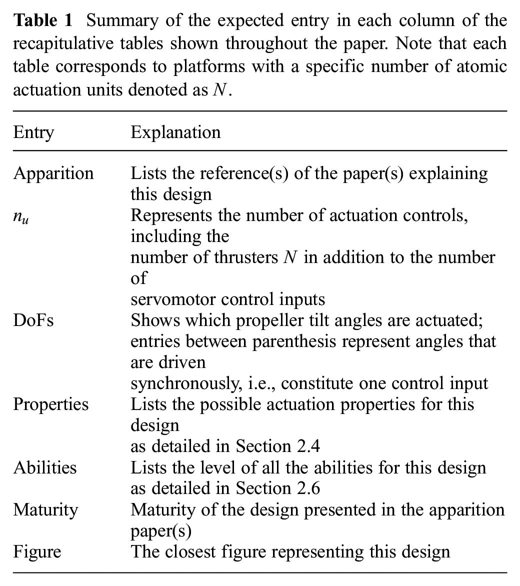
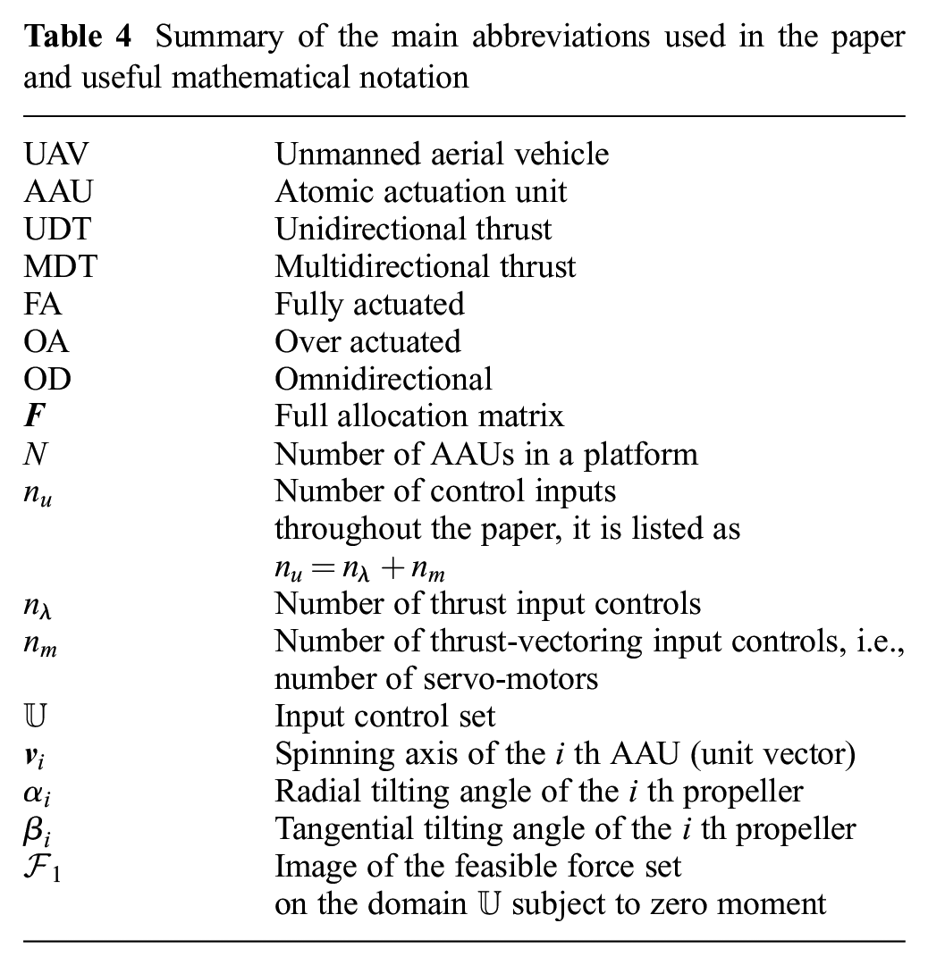
A complete revision of the majority of MAV designs from the literature, describing them using the above taxonomy. To help the reader, we present each reviewed platform following the increasing number of rotors. In this way, it is natural for the reader to understand what a given platform is capable of. At the same time, the question of which design possesses a given property is provided in an extensive set of summarizing tables across the paper. For a complete understanding of these tables, we provide a summary of all the abbreviations and symbols in Table 1.
An insight of the manoeuvrability and field of application of each of the mentioned designs.
A concrete analysis of the feasible force set of each of the reviewed designs.
Insight on the limitations that we could find in the literature, as well as provide our vision on the directions that should be explored to advance the field of MAV design.
Summary of the expected entry in each column of the recapitulative tables shown throughout the paper. Note that each table corresponds to platforms with a specific number of atomic actuation units denoted as
The rest of the paper is organized as follows. Section 2 provides the required definitions to structure the discussion, as well as the modeling of generic multirotor design. Section 3 groups the analysis of different designs based on the number of motors generating thrust. The main findings and generalities that can be extracted from the review are then summarized in Section 4. Finally, conclusions are drawn in Section 5.
2. Definitions and conventions
2.1 Review scope
In this paper, we focus our analysis on multirotors, i.e., rotary-wing vehicles, for which the control inputs are solely the spinning velocities of each propeller and, possibly, the propeller orientation. This scope excludes UAV designs where propellers are mixed with wings in which the control input also comprises the wing geometry, i.e., designs in which a subsequent part of the lift is generated by fixed-wing. Some examples are those of Bronz et al. (2017) or the hybrid designs reviewed in Saeed et al. (2015). The scope of this review also excludes multirotors with variable pitch propeller mechanisms, where the propeller pitch is a control input rather than, or in addition to, the propeller speed, e.g., the quadrotor-based design in Michini et al. (2011). Although fixed-speed/variable-pitch propellers provide an alternative for single-input control of thrust, it complicates the ensuing derivation of the platform’s dynamics due to the change in relation to the propeller’s thrust and drag at a given speed without adding to the taxonomy. Designs in which the motion of weights is used as control input are also excluded, e.g., the quadrotor-based design in Haus et al. (2016). In addition, designs in which the multirotor center of mass (CoM) is time varying are also out of the scope of this paper. This includes some of the previously mentioned cases but also designs where weight motion participates in the system stabilization. Examples of such stabilization systems can be found in Haus et al. (2017), Zhao et al. (2017), and Anzai et al. (2017). Nevertheless, to accommodate for manufacturing imperfections and mechanical constraints, we consider the non-moving CoM in a relaxed way, allowing small displacements of the CoM owing to the motion of the actuators. Lastly, designs where the weight is partially or totally lifted by means other than the rotating propellers are also excluded. This category includes for example platforms lifted through a gas such as helium or ropes, similar to the design presented in Festo AG & Co. KG (2016) and Sarkisov et al. (2019).
Consequently, the considered designs include the control quantities related to: (i) the spinning propellers, each producing mainly a thrust (a lift) and a drag moment; and, possibly, (ii) the vectorization of their orientation in the body frame.
2.2 Design framework
Under the previous assumptions, to describe the various possible designs of small multirotors, we propose a general abstract framework defined as follows.
the number of AAUs, denoted by
the type of every single AAU; and
the arrangement of the AAUs (position and attitude).
For the sake of classifying multirotor platforms according to the properties related to their actuation (actuation properties), we consider here only the design parameters directly linked to the vehicle actuation. On the other hand, we do not consider design parameters such as total weight, flight electronics, power source, materials, the shape of the structure, and so on. Although very important for the final development of an aerial platform, those parameters are tailored by the particular application and do not grant the platform particular properties of interest for this study.
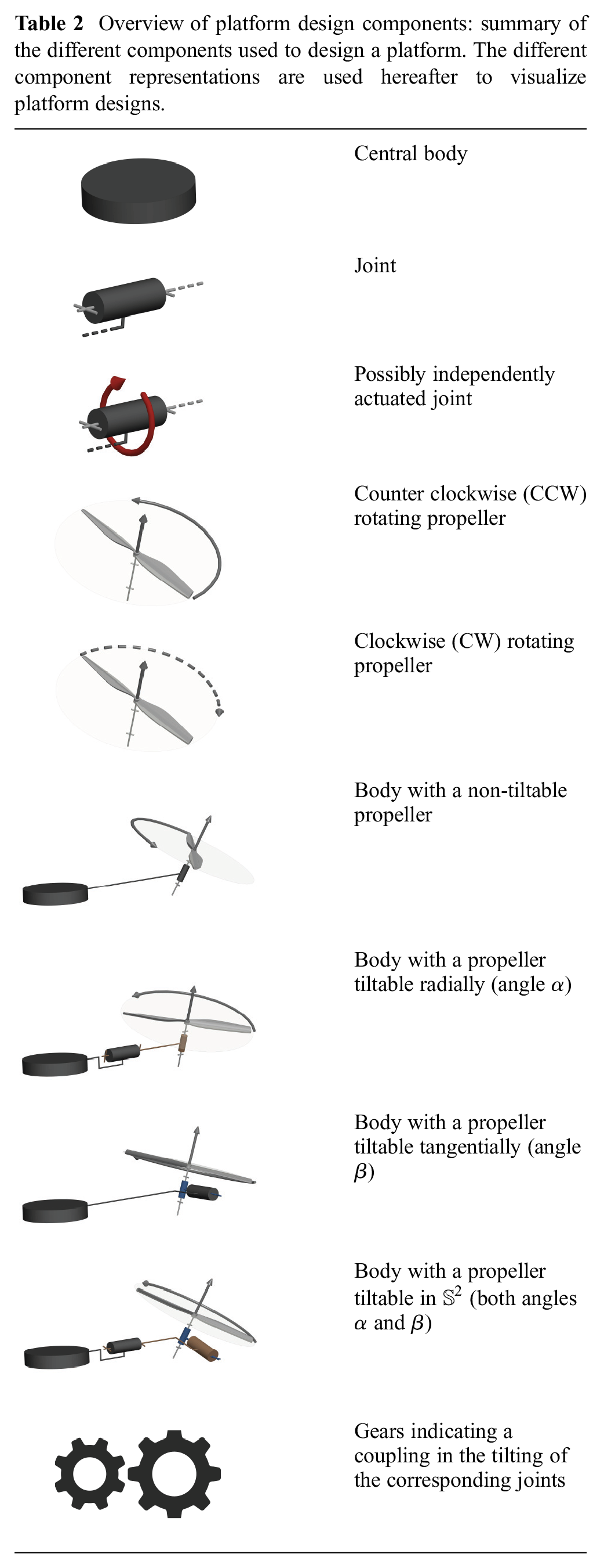
Overview of platform design components: summary of the different components used to design a platform. The different component representations are used hereafter to visualize platform designs.
We denote by
AAUs
These are the mechatronic components generating thrust. They are the core of each multirotor design. In the literature, they typically consist of a brushless motor with a single propeller.
Considering a generic
In addition, we define a frame
It is convenient to parametrize
These two rotations can be combined into a single rotation matrix
2
The propeller rotation produces a thrust
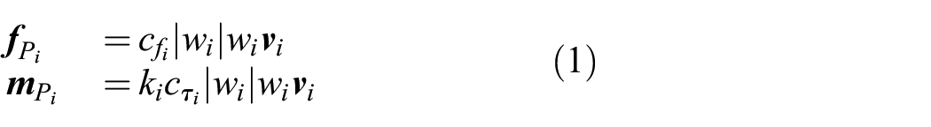
where
As is normally done in the related literature, in (1) we neglected all the secondary inertia and aerodynamic effects, such as centripetal and flapping effects (see Mahony et al., 2012). In fact, in the considered working conditions, these are negligible with respect to the main thrust and drag moment contributions.
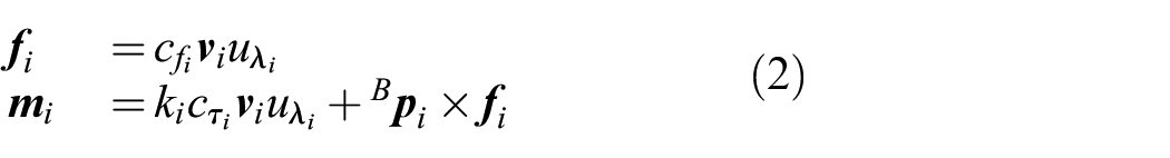
Assuming that the brushless motor can control
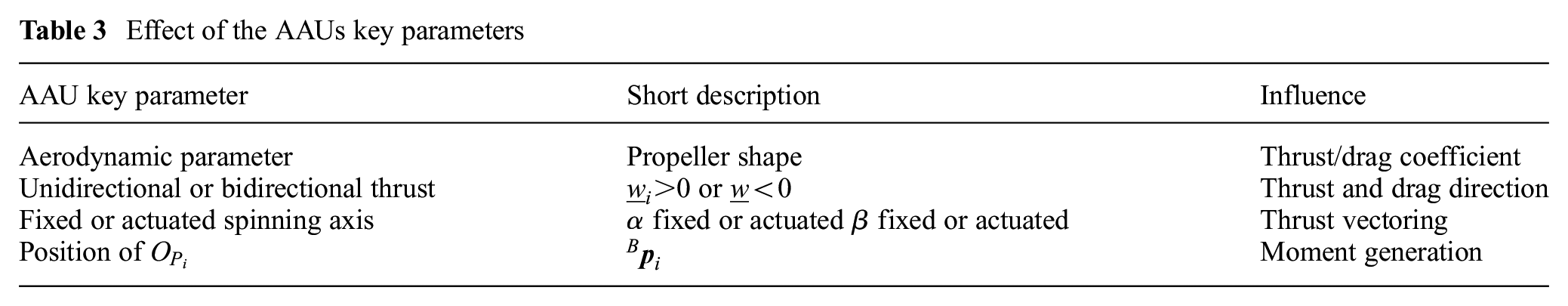
The parameters required to characterize AAUs are as follows.
1. Aerodynamic parameters. The shape of the propeller is an important design factor that defines the lift and drag coefficients, i.e.,
2. Unidirectional or bidirectional thrust. The second key parameter to consider is the direction of the thrust along the spinning axis. In general, the majority of UAVs in the literature are designed such that the brushless motor controllers rotate the propellers only in one direction, i.e.,
Although this solution enlarges the thrust range, it usually results in a lower thrust magnitude with respect to unidirectional propellers for the same spinning velocity. In fact, it requires propeller designs that are symmetric enough to generate thrust in both directions equally.
3. Fixed or actuated spinning axis. The third key parameter to consider for each AAU is its ability to reorient its thrust, either actively or passively. In this case we have that

where
In what follows, we consider
4. Position of
Table 3 gathers the previously mentioned parameters and their effects on the produced total thrust and moment. Table 4 summarizes the main abbreviations and notations used in this section and the rest of this paper.
Effect of the AAUs key parameters
Summary of the main abbreviations used in the paper and useful mathematical notation
2.3 Platform equations of motion
Let us consider a world frame
Considering the body frame
For the sake of compactness, we introduce the following notation. Let
Let us define
Where
3
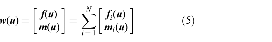
To characterize
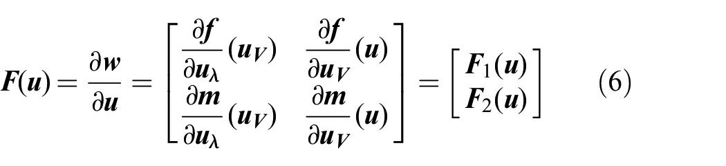
We decompose
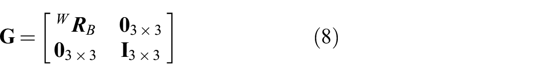
Following the Newton–Euler formalism, we can derive the dynamic equation of a multirotor as follows:
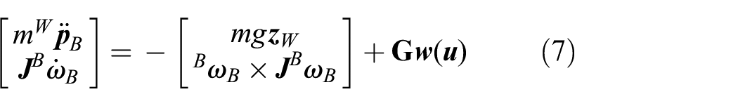
where
where
In the case of a platform where
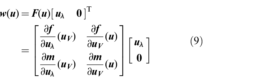
As can be seen in (9), in this case the second column of
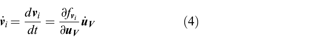
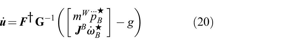
On the other hand, in the case of a platform actively tilting at least one of its propellers, we have to differentiate (7) to make the full allocation matrix appear:
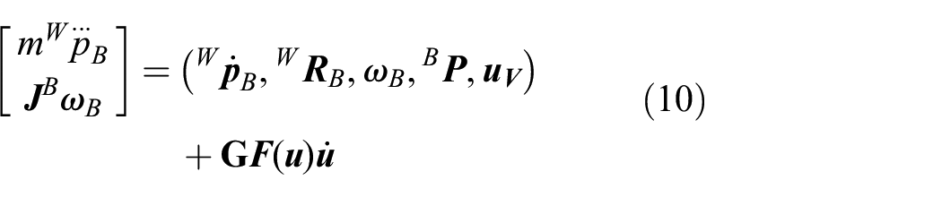
where
Note that the model in (7) and correspondingly in (10) is valid under the following assumptions:
motor actuators are controlled by a fast high-gain local controller, to have a negligible transient;
gyroscopic and inertial effects due to propellers and motors are considered second-order disturbances that are neglected in the model and can be compensated for by the controller itself, as specified previously;
aerodynamic interactions between adjacent propellers are considered negligible, and, again, left to the robustness of the feedback controller;
the counter torque on the body produced by a servomotor rotating a propeller is considered negligible and compensated for by the controller.
2.4 System properties
One of the most important characteristics of a design is the set of the admissible wrenches
unidirectional thrust (UDT);
multidirectional thrust (MDT);
fully actuated (FA);
over-actuated (OA);
omnidirectional (OD).
The interactions between the properties of classes (1)–(5) are depicted in Figure 1.
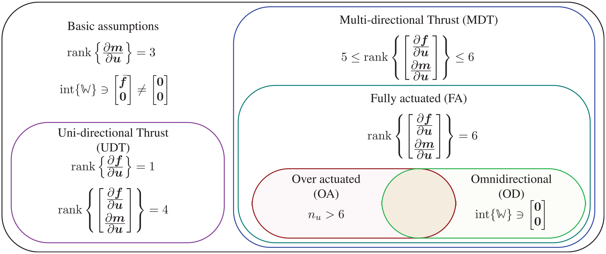
interaction between thrust related properties for multirotor designs.
All the listed classes have properties that extend two basic properties holding for any multirotor design and listed in the following.
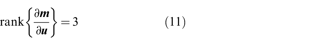
This means that for any multirotor design the orientation dynamics is always fully actuated.
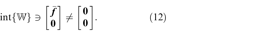
The above two properties are sufficient for the platform to reorient itself in space, and apply a force in at least one direction to counteract its weight without applying any moment (in average), thus remaining in hovering at the equilibrium. These properties are enough for the platform to hover in place, or to move around while being in the near-hovering mode. However, they do not guarantee any decoupling between the moment and the desired force direction. Further properties extend these two and better characterize
2.4.1 UDT
This describes platforms for which the total thrust can be varied only along one direction ( e.g., in coplanar/collinear designs). This property can be expressed as
2.4.2 MDT
This describes platforms for which the total thrust can be varied along more than one direction independently from the total moment (see, e.g., designs by Kawasaki et al. (2015)) and can be expressed as

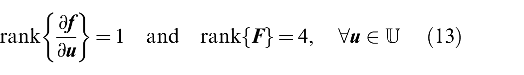
2.4.3 FA
This describes a sub-class of MDT platforms, for which the total thrust can be varied along all directions independently from the total moment:

2.4.4 OA
This term typically describes platforms for which there are more actuation inputs,

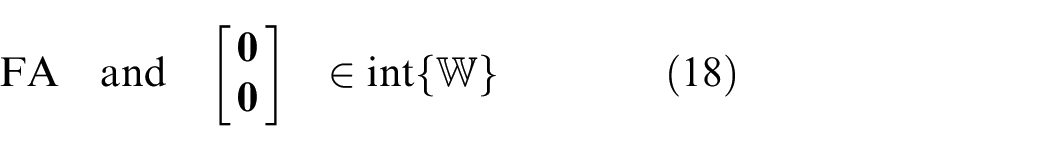
2.4.5 OD
This describes another sub-class of FA designs, not exclusive from OA, where the total thrust can assume any value in a spherical shell independently from the total moment:
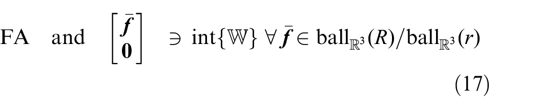
Where
4
The OD property can also be understood from the attainable wrench set
where
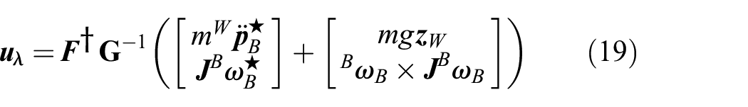
In case of orientable AAUs, we can define the dynamic input extension
where
In both cases, the virtual inputs can be computed with a simple linear state feedback that makes
If the platform is also OA, the null space of
On the other hand, if the platform is not FA, feedback linearization cannot be applied directly, and particular attention should be dedicated to the design of the control law. As an example, for the case of a quadrotor, a first input transformation is required in order to consider as input the total thrust and moments. Afterwards, the dynamics need to be differentiated two additional times (up to the snap level) to obtain a full-rank allocation matrix, and apply feedback linearization. Note that, in this case, one needs to consider as a new input the total moment and the second derivative of the total thrust (Mistler et al., 2001).
Although these properties reflect the ability of the platform to apply forces and moments in certain directions and combinations, they do not directly reflect its ability to maneuver, stabilize its position, or interact with its environment. These abilities are affected by the set of feasible control input,
2.5 Feasible wrenches
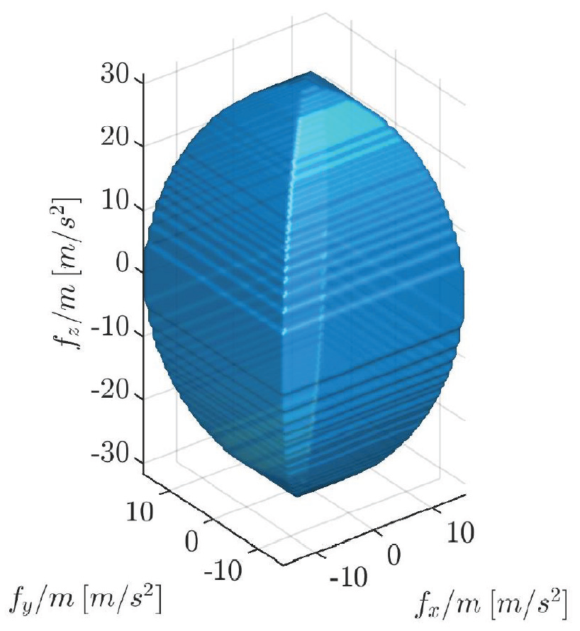
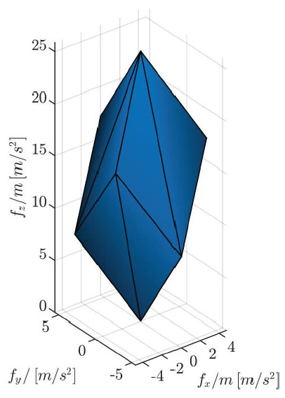
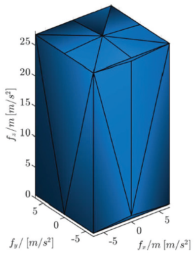
To assess the reachable allocation capabilities of platform designs, we present throughout the paper a set of representative figures relative to the attainable wrench set
For the sake of the representation of
2.5.1 Case 1: Fixed propellers
In the case of fixed propellers, we note that

As such,

Owing to the linear relations in (21) and (22),
The extreme points of
2.5.2 Case 2: Independently tilting propellers
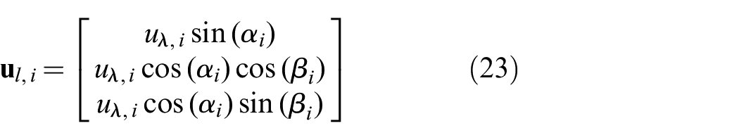
In this case, by a wise change of input coordinates, from
Considering the representation of
For a fixed propeller,
For a propeller with only radial tilting,
For a propeller with only tangential tilting,
For a propeller tilting in
To find
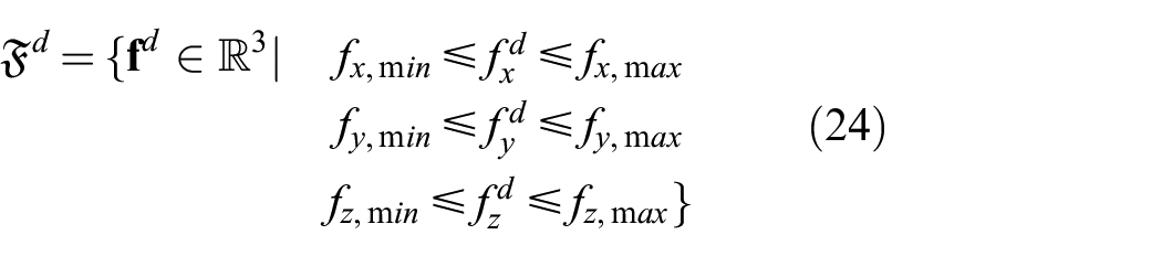
where the range of each force is the expected one given the platform geometry.
Let us consider
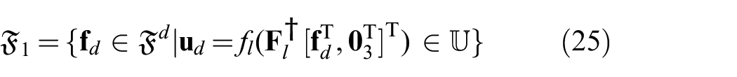
Note that in the case where
2.5.3 Case 3: Jointly tilted propellers
We represent
2.6 System abilities
The system abilities are expressed with respect to the tasks that can be achieved by the multirotor according to its design. They are all directly related to the attainable wrench set
2.6.1 Hovering ability
The ability to hover corresponds to the ability of the platform to remain stationary at the desired position. This represents the main advantage of multirotors over fixed-wing UAVs.
In detail, in the scope of this study, we define static hovering as the ability of the platform to stabilize its position and orientation for some
Note that in the case of static hovering, it is assumed that the platform can rotate about its

Finally, we define dynamic hovering (or relaxed hovering) as the ability of the platform to keep the position error bounded while varying its linear and angular velocity. In other words, for these platforms static hovering is not feasible, i.e.,
Following the above definitions, we define the following categories of hovering.
Categories
2.6.2 Trajectory tracking ability
The ability to follow a trajectory is fundamental for many multirotor applications such as surveying, surveillance, and delivery. We propose to categorize the trajectory tracking ability based on the type (position and orientation) and the number of DoFs the multirotor can track independently. While some platforms can trade-off the tracking in position for its orientation counterpart, in our classification we consider positional tracking to have a higher priority than orientation tracking. As such we consider the three-dimensional position tracking ability as a baseline for the tracking ability classifications listed in the following.
2.6.3 Physical interaction ability
We also consider the ability to physically interact with the environment, following the rising trend of aerial physical interaction ( APhI ) in the last decade. In particular, we decided to separate the possible APhI abilities according to the following classifications:
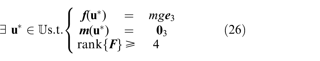
It should be noted that the APhI abilities require suitable hardware for the specific task, and an adequate level of force and moment decoupling. As explained by Michieletto et al. (2018), the decoupling between force and moment allows a platform to apply forces in one or more directions while applying null moment. This is a requirement to physically interact with a static environment while maintaining hoverability. It should be noted that the force–moment decoupling of a design can be derived from the study of its full allocation matrix
2.6.4 Level of maturity
Given the vast literature on multirotor design, we decided to also stress the level of maturity to distinguish purely theoretical contributions from designs that have been constructed and tested in various scenarios. While the theoretical grounding of any design is of paramount importance, we believe that each should be tested by real experiments verifying the corresponding findings. To this goal, we include in our assessment the level of maturity of each design, where the level can be one of the following:
theory;
simulation of the simplified model (simplistic simulation);
simulation with uncertainties and/or second order effects (far from ideal simulation);
prototype; and
product.
Results deemed as theoretical comprise work where the analysis of the design is conducted without any simulation or prototype. On the other hand, we separate simulation proven designs into two categories, where simplistic simulations that serve as a proof of concept are distinguished from realistic simulations, which include delays, noise, model discrepancies, external perturbations, and so on. The latter reflects a higher degree of maturity of the work and a smaller gap to real experiments. Finally, we label as prototype any work presenting a functional prototype of the proposed design. The final level of maturity would describe designs implemented as commercial products, but we note that such occurrences are rare.
3. Unirotor (one AAU)
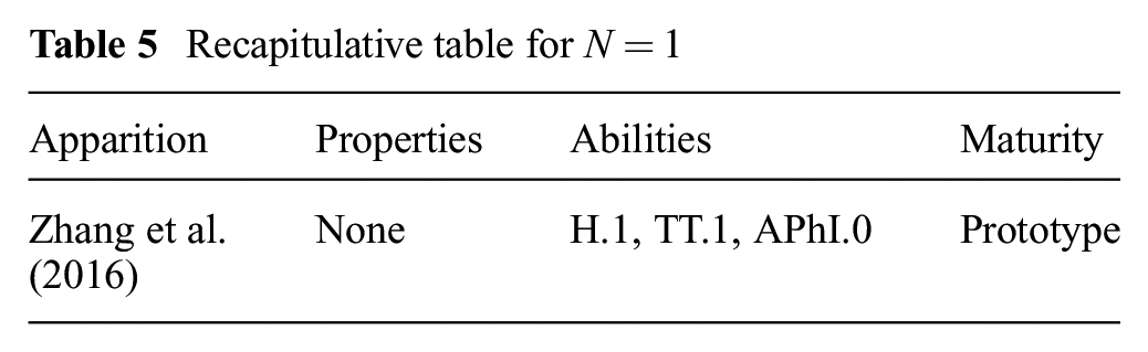
Even though the case of a multirotor composed of a single AAU is a contradiction in itself, it is considered for completeness of the review; in addition, it can represent a configuration reached in the case of extreme failure of multirotors. To the best of the authors’ knowledge, the only occurrence of such design fitting this paper scope ( i.e., excluding moving mass and control surface) can be found in Zhang et al. (2016).
The proposed approach relies on active control and demonstrates a position tracking controller for such a vehicle. Due to its single rotor
Recapitulative table for
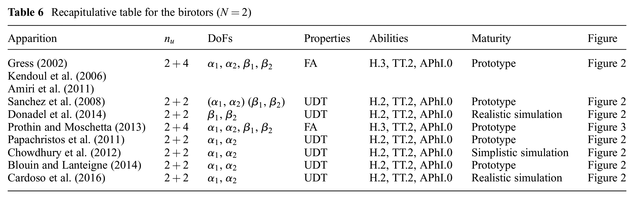
4. Birotor (two AAUs)
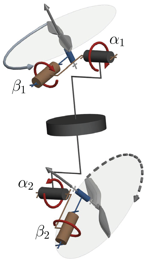
Birotors are composed of only two AAUs as their name suggests (Table 6). For these designs, hovering can only be achieved if thrust vectoring is controlled, i.e., the total thrust is dynamically oriented during flight. The two AAUs are always rotating in opposing directions to have a zero total drag moment when the propellers spin at the same speed, thus the platform can hover without being subjected to constant rotation. In addition, in most designs, the multirotor CoM is placed between the two AAUs to benefit from a damped pendulum dynamics, such as in the work of Chowdhury et al. (2012), where a wing-tail was also added for stabilization as shown in Figure 2.
Recapitulative table for the birotors (
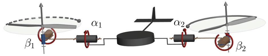
Conceptual 3D kinematic representation of a generic birotor design with wing-tail stabilization.
4.1 Tilting in
Designs
The fist pioneering work on birotor design was presented by Gress (2002), in which the inertia and gyroscopic characteristics of the multirotor are exploited to control the roll, pitch, and yaw in order to achieve a stable hover. The two AAUs are devised to be tilting in
Another platform presenting propellers tilting in
Prothin and Moschetta (2013) presented another design, named the “donut,” made of two AAUs aligned vertically with the center of the multirotor frame, which can be tilted independently in
Conceptual three-dimensional kinematic representation of the birotor design presented in Prothin and Moschetta (2013)
4.2 Radial and tangential tilting designs
A birotor design often found in the literature is presented in Papachristos et al. (2011), where the platform has two AAUs placed on an axis above the CoM of the platform, and tilting independently radially about their axis, thus resulting in
A similar design was presented by Chowdhury et al. (2012), where the authors proposed a controller that changes the tilt angles to achieve desired roll and yaw independently and demonstrated their controller in simulation. Another similar controller was proposed by Blouin and Lanteigne (2014), however, they tested their controller on a prototype. Finally, Cardoso et al. (2016) presented a robust controller for this platform design and showed its path-tracking ability in a realistic simulation under external disturbances and model uncertainties.
Donadel et al. (2014) proposed a design where the tangential tiltings are fixed and the two radial tiltings are actuated, hence, again,
5. Trirotor (three AAUs)
Trirotors are composed of three AAUs. As such, they can be considered as an upgrade from birotors, but they pose a challenge due to the unbalanced moment caused by the odd number of propellers. In addition, and similarly to birotors, the low number of actuators imposes limitations on the achievable performance, in particular in the ability to perform stable hovering (Kataoka et al., 2011).
One of the first trirotor designs appeared in Rongier et al. (2005), where propellers are tilted at a fixed angle so that a non-collinear thrust is ensured. The control is based on a combination of aircraft gyroscopic effect with a piezosensor to detect the tilt angle (pitch and roll) with respect to the horizontal orientation. However, the lack of control of the yaw angle forces the rotor to constantly rotate about its CoM, thus being unable to achieve the basic static hovering ability (
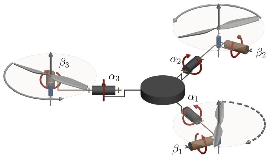
Conceptual three-dimensional kinematic representation of a generic trirotor
Multiple designs have been later proposed in the literature that aim to balance the odd shape of the trirotor, which we group into T-configurations and
5.1 T-configuration
This setup is composed by two frontal principal propellers, that may be dynamically tilted or fixed, spinning in opposite directions, with a third propeller (typically smaller) mounted on a tail as shown in Figure 5. This one, in general, tilts around the radial axis in order to improve pitch and yaw control.
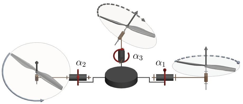
Conceptual three-dimensional kinematic representation of a generic trirotor T-configuration design. The tail propeller (typically smaller and weaker) is depicted on the top while the frontal principal propellers (typically larger and stronger) are on the bottom. The sagittal axis points down in the picture.
5.1.1 Tail-only tilting propeller
This design was presented in Salazar-Cruz and Lozano (2005), followed by Salazar-Cruz et al. (2009). The tail-propeller is endowed with a servo motor which allows the control of the yaw motion by tilting about the sagittal axis, and the pitch angle regulating the propeller rotational speed. The two main frontal fixed propellers are in charge of the control of total thrust and roll angle. In total, we have

Visualization of the
In the mentioned works, the hovering and the forward flight control of this vehicle were achieved using a non-linear controller based on nested saturations. The same design is instead controlled in Yoon et al. (2013) with an optimal linear–quadratic regulator (LQR) to control the attitude. All these works have been validated with an experimental prototype.
5.1.2 Frontal-propeller tilting
In a design presented in Papachristos and Tzes (2013) and Papachristos et al. (2014, 2016), the two frontal principal propellers are also able to tilt radially with the same (locked) tilting angle, while the tail rotor can tilt independently, thus obtaining
A commercially available T-configuration trirotor is the Cerberus Tilt-Rotor.
5
In this product the two frontal principal propellers can tilt radially independently, while the tail propeller is fixed, thus obtaining again
5.2
-configuration
This design is composed of three propellers of the same dimension arranged on a triangle, with two of them spinning in opposite directions. In addition, in these configurations the thrust is roughly shared equally by all three motors, encouraging the symmetrical placement of the motors on a circle ( i.e., every
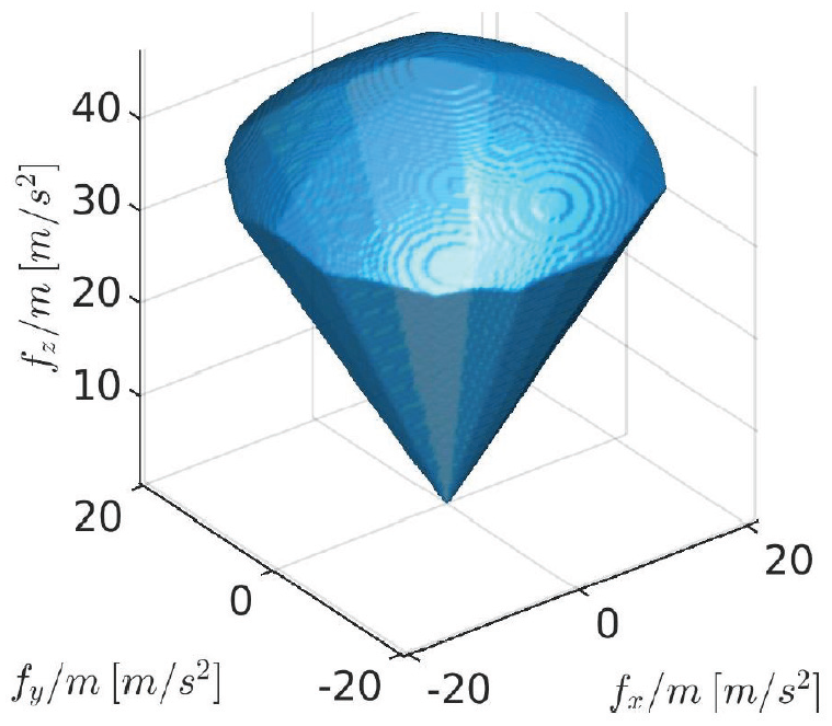
One example design was presented in Escareno et al. (2008), where the authors built a
Another
visualization of the
On the other hand, Ramp and Papadopoulos (2015) presented an over-actuated system, where each of the three propellers is allowed to rotate independently in both its tangential and radial direction, thus obtaining
visualization of the
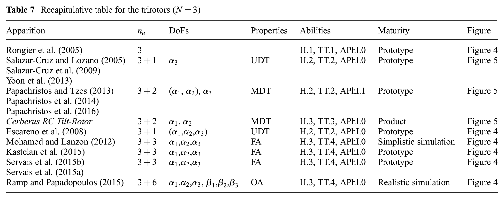
Table 7 summarizes all the presented designs.
Recapitulative table for the trirotors (
6. Quadrotor (four AAUs)
This case is of particular interest because for designs with fixed AAUs,
The first documented quadrotor design in the literature traces back to 1907 and documented in Young (1982). While this design recorded a few tethered flights, the modern quadrotor design (Pounds et al., 2002) traces its origin back to the same platform concept, however, technological advancements within the last century has allowed new platforms to be built with compact electronics and sensors, allowing robust and agile maneuvers.
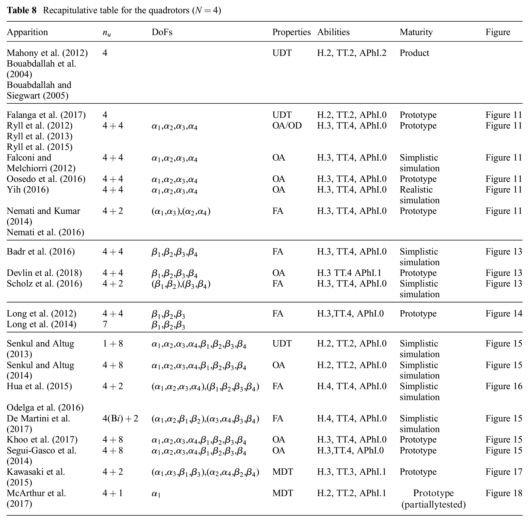
While the first designs relied on a coplanar/collinear propeller configuration, later modifications were conducted to extend the system properties via thrust-vectoring. All the presented designs consider the AAUs and the CoM to be located roughly on the same plane. We refer to Table 8 as a summary of the presented designs.
Recapitulative table for the quadrotors (
6.1 Coplanar/collinear designs
For modeling, control, and the general theory of classical coplanar/collinear designs one can refer to Mahony et al. (2012), Bouabdallah et al. (2004) and Bouabdallah and Siegwart (2005), and Pounds et al. (2010), which are three comprehensive references among the vast literature of such designs. We present an example of
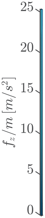
Visualization of the
Note that the wide attention gathered by coplanar/collinear quadrotors comes from the combination they offer between their simple mechanics and relative easiness of control for trajectory tracking, thanks to the dynamic feedback linearizability (or, equivalently, the differential flatness) of the non-linear system dynamics (Mistler et al., 2001).
This enabled a vast set of applications for coplanar/collinear designs. Innovative modular designs such as that presented in Zhao et al. (2017), exhibit the same properties as classical coplanar/collinear designs, although they lie outside the scope of this paper due to their varying CoM with each new configuration.
In addition, coplanar/collinear designs for
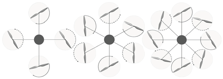
Top view of the conceptual kinematic representation of coplanar designs with (left to right) four, six, and eight propellers.
6.2 Radial tilting designs
Some designs consider AAUs which are radially tilted/tilting in order to achieve total thrust vectoring for quadrotors as shown in Figure 11. Within the other two tilting directions, this particular design can be considered as the simplest mechanical extension to the coplanar/collinear design achieving thrust vectoring.
Conceptual 3D kinematic representation of a generic quadrotor with propellers tilting/tilted about their radial axes.
Falanga et al. (2017) presented a quadrotor with propellers tilted
Ryll et al. (2012) proposed a configuration, further analyzed in Ryll et al. (2013, 2015), where four additional servomotors are used to independently radially tilt the AAUs, thus obtaining
Visualization of the
Falconi and Melchiorri (2012) considered a similar design with the implementation of an inverse dynamic controller, to compensate for the non-linear dynamics, and a PD with feedforward to impose a position and attitude trajectory. Similarly to Ryll et al. (2015), Falconi and Melchiorri (2012) solved the allocation problem using a pseudo-inverse approach. This approach is more sensitive to model uncertainty due to the complexity of the aerodynamic modeling.
Oosedo et al. (2016) studied a wide range of platform orientations in addition to the transition from horizontal to vertical hovering of the multirotor. Position and orientation are regulated through a PID loop while control allocation techniques for two orientation sets are proposed and validated experimentally.
Yih (2016) authors considered the same design subjected to model uncertainties. They proposed a robust sliding mode controller for position and orientation tracking, augmented with a chattering suppression block to improve its performance. The proposed model and control law were validated in simulation.
Nemati and Kumar (2014) considered similar radial tilting of the AAUs while constraining paired AAUs to tilt the same angle in opposing directions, thus obtaining
6.3 Tangential tilting designs
Another attempt at extending the classical quadrotor design is to consider tangential tilting of the AAUs, see Figure 13, as in Badr et al. (2016), which has also
Conceptual three-dimensional kinematic representation of a generic quadrotor with propellers tilting/tilted about their tangential axes.
Scholz et al. (2016) also studied the design shown in Figure 13. To control the platform they synchronized the rotational speed of each of the four AAUs, then derived an input allocation scheme based on heuristics and proposed a backstepping approach. The controller tracks the desired orientation, altitude, and velocity in the plane, and is robust to unmodeled dynamics. The authors rely on optimization techniques to tune the controller gains. This approach is corroborated with simulation comprising sensor noise.
Another design with tangential tilting of the AAUs can be found in Long et al. (2012), with
Conceptual three-dimensional kinematic representation of the quadrotor design presented in Long et al. (2014, 2012). The three non-central propellers are tilting about their tangential axes independently.
Long et al. (2012)used a backstepping approach and a PID loop to achieve decoupled tracking of both orientation and position. The control allocation is achieved by considering a linearization of the system around the functioning point. Long et al. (2014) proposed the same design with only one central AAU to improve the efficiency of the design. They apply the same control technique for the second design and validate both designs via real experimentations on a prototype.
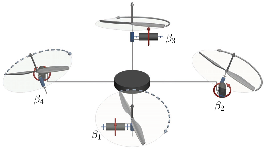
6.4 Tilting in
designs
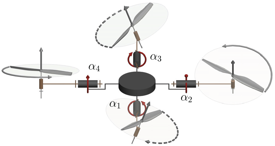
The following designs explore the AAUs tilting in
Conceptual three-dimensional kinematic representation of a generic quadrotor with propellers tilting/tilted in
The first original design can be found in Şenkul and Altuğ (2013, 2014), where the authors considered a classical quadrotor with each AAU being able to tilt both radially and tangentially. Şenkul and Altuğ (2013) considered all AAUs to tilt independently while rotating at the same speed, hence
Similarly to Şenkul and Altuğ (2013), Hua et al. (2015) proposed to study a quadrotor tilting in
Conceptual three-dimensional kinematic representation of a quadrotor with propellers tilting/tilted in
The same design as shown in Figure 16 was explored in Odelga et al. (2016), with the addition of an explicit mechanism design that enforces the angles to rotate equally, whereas in Hua et al. (2015) it was only theoretically assumed. Full-actuation allows the use of a standard feedback linearization control with dynamic extension, which is validated by simulation. The introduction of a real mechanism makes explicit the constraints induced by the mechanism limits. Therefore, tracking performances are limited by unidirectional rotors and tilt angle limits, despite the full actuation nature of the design.
De Martini et al. (2017) also presented a quadrotor design with propellers tilting synchronously in
The above contributions have presented analyses and simulations studying quadrotors with propellers tilting in
Khoo et al. (2017) implemented a design as shown in Figure 15 that allows independent rotation of all propellers, thus obtaining
Segui-Gasco et al. (2014) also built a prototype, while considering tilting limits of each AAU in its control. The dynamics of the system are derived while considering the gyroscopic moment produced by the fast tilting AAUs. The authors consider a coplanar/collinear quadrotor controller, with body orientation and total thrust calculated through system linearization and weighted pseudo-inverse. The over-actuation of the system calls for control allocation, which is calculated in an energy-optimal way. The authors validated their approach with a hovering maiden flight, and their design analysis suggested the need for high inertia propellers to increase the produced torque and allow higher vehicle speeds.
Another design with the AAUs tilting in
Conceptual three-dimensional kinematic representation of a quadrotor with propellers tilting in
McArthur et al. (2017) presented a quadrotor design based on the composition of a
Conceptual three-dimensional kinematic representation of a quadrotor with propellers tilting/tilted radially/tangentially as presented in McArthur et al. (2017).
While the quadrotor design was exploited extensively in the literature and allowed platforms to reach OA/OD, the limited number of propellers does not allow the platforms to exhibit more than UDT and
7. Pentarotor (five AAUs)
The case of
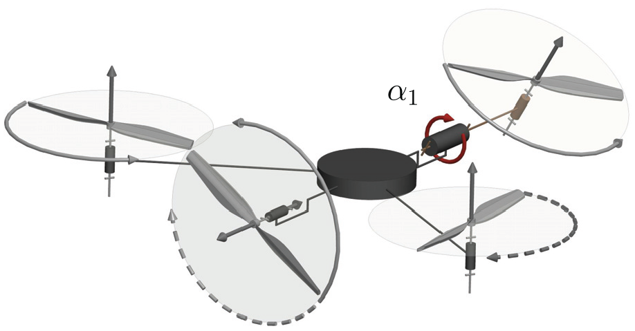
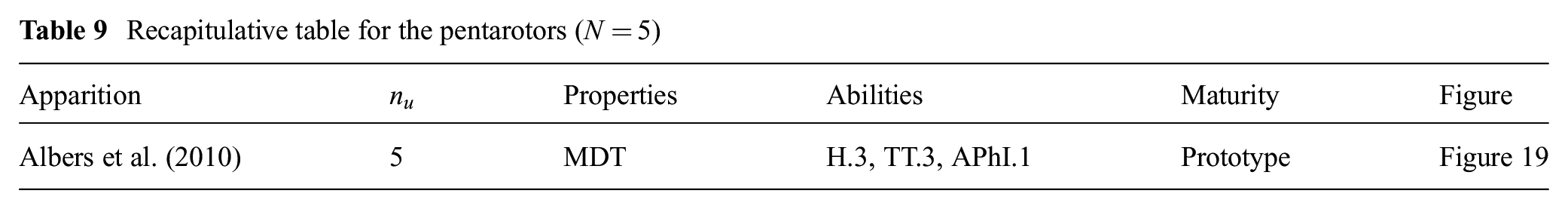
The only documented non-coplanar/collinear pentarotor design we could find is introduced in Albers et al. (2010) and can be described as a classical coplanar quadrotor with the addition of a propeller oriented in an orthogonal direction to provide extra actuation for attaining the considered tasks; a conceptual design sketch is shown in Figure 19, and the design properties and abilities are listed in Table 9. The goal is to be able to easily apply a normal force on a wall for tasks such as inspection, cleaning, and painting. All the AAUs’ orientations are fixed, thus
Conceptual three-dimensional kinematic representation of the pentarotor design presented in Albers et al. (2010).
Recapitulative table for the pentarotors (
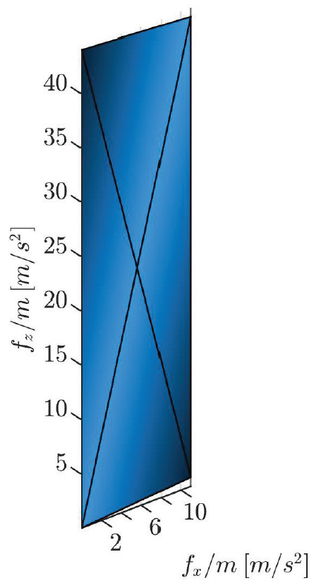
Visualization of the
8. Hexarotor (six AAUs)
A hexarotor design has
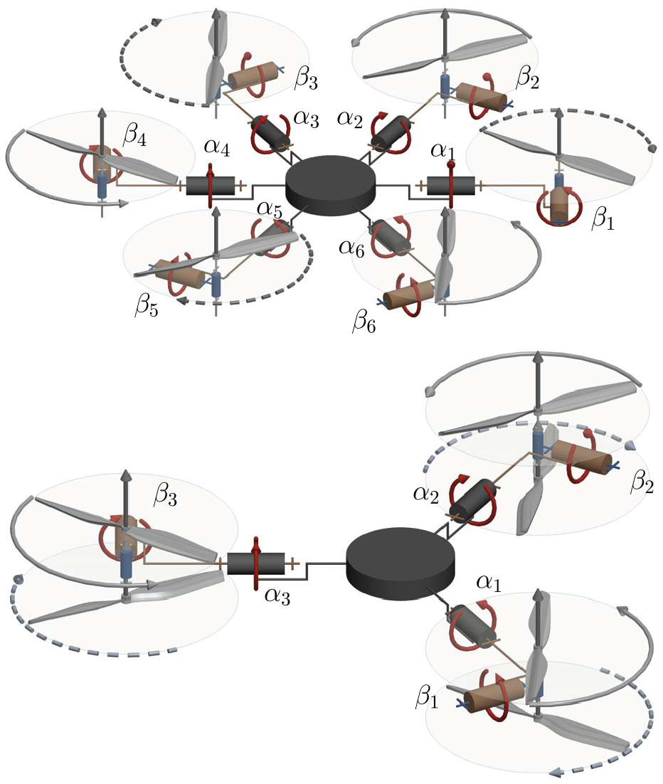
Conceptual three-dimensional kinematic representation of (top) star-shaped hexarotor and (bottom) Y-shaped hexarotor with propellers tilting/tilted in
As for hexarotors with tilted AAUs, tilting angles can be chosen so that
As most of the hexarotor designs found in the literature consider unidirectional fixed-tilt AAUs, thus obtaining
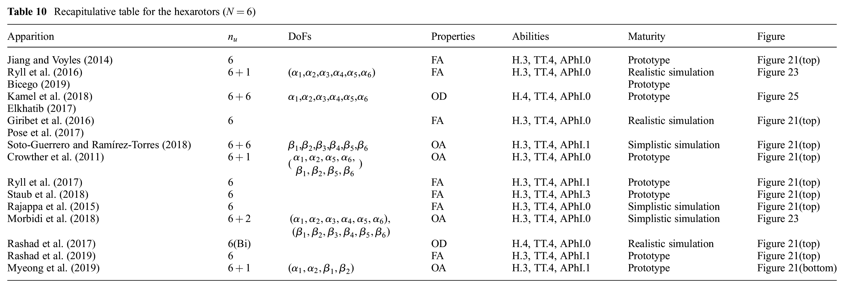
Recapitulative table for the hexarotors (
8.1 Radial tilting designs
In Jiang and Voyles (2014) (and previous work) the design focused on allowing force closure, i.e., the ability to instantaneously resist six-dimensional wrench perturbation such as wind while in contact with the environment. To obtain such a design, AAUs are radially tilted by a constant angle of
Visualization of the
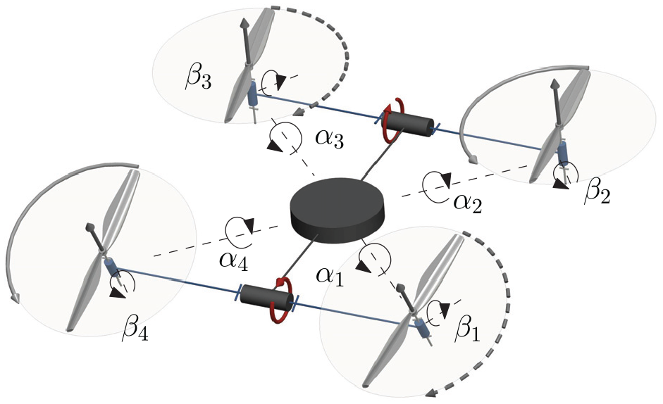
On the other hand, Ryll et al. (2016) presented a design called FastHex where AAUs’ radial tilting can be changed simultaneously with a single servomotor for all AAUs as shown in Figure 23, thus obtaining
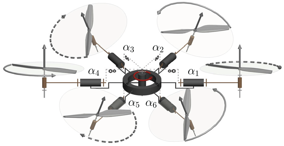
Conceptual three-dimensional kinematic representation of the FastHex design presented in Ryll et al. (2016). The propellers are tilting radially. Highlighted the locked tilting that forces all the propellers to tilt of the same angle
Visualization of the
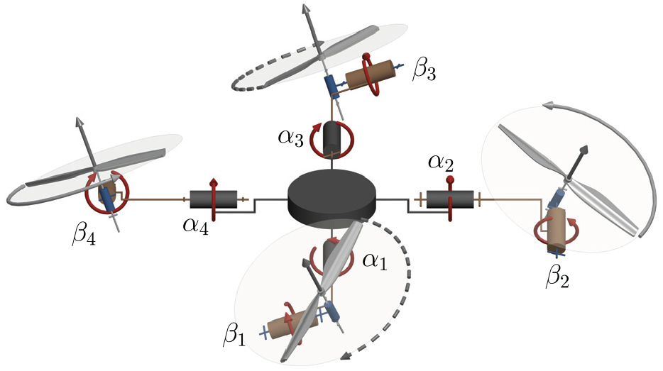
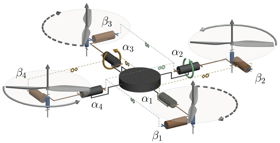
In Kamel et al. (2018) and Elkhatib (2017), each AAU is equipped with a servomotor (six in total) to tilt independently, thus obtaining
Conceptual three-dimensional kinematic representation of the Voliro design presented in Kamel et al. (2018) and Elkhatib (2017). The propellers are tilting radially and all independently.
8.2 Tangential tilting designs
Differently from the designs in Section 8.1, Giribet et al. (2016) proposed a design where the AAUs are tangentially tilted, at a magnitude chosen heuristically at
Pose et al. (2017) also proposed a design relying on tangentially tilted AAUs, where the tilting angle is heuristically chosen in a range that ensures the robustness of the design to failures, at a fixed
The above two designs are mechanically equivalent despite the different choice of tilt angle
Another design is proposed in Soto-Guerrero and Ramírez-Torres (2018), where the authors combined a hexarotor with a hexapod design, mounting each propeller on one of the platform’s legs, which can rotate about two axes corresponding to the propeller’s arrangement about the CoM, and the propeller’s tangential tilt. The platform is able to crawl and fly, and hence its name hexapodopter. The authors prove that their design can achieve FA, and assess their design through simulation.
8.3
tilting designs
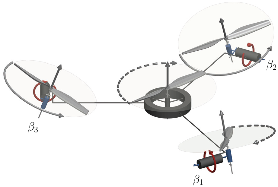
Crowther et al. (2011) presented a hexarotor design where each AAU is allowed to tilt in
Conversely, the following works considered the tilting of the AAUs in a more general way, i.e., not enforcing orthogonality of the individual thrusts. In addition, we note that most works considering generic AAUs orientation in
Another design was proposed in Mehmood et al. (2016), where the tilt angles about
Tadokoro et al. (2017) investigated an optimal design based on “dynamic manipulability measure.” It can be understood as omnidirectional acceleration capabilities similar to the manipulator case and is expressed as
Both methods rely on heavy symmetry constraints imposed on the design, in terms of AAU disposition and tilting. Interestingly, the optimal design for these two metrics does not require AAUs to be oriented in
The aforementioned maxima are also acknowledged in Rajappa et al. (2015), where the AAU tiltings are adjusted before flight such as to minimize the norm of the control effort upon the desired trajectory. Indeed, it is important to underline that the optimal value of the tilt angles is highly dependent on the specific trajectory that the UAV has to perform. The problem has been solved searching for an optimal arrangement with respect to a minimum control effort over a desired trajectory. In the end, a feedback linearization technique has also been exploited.
Ryll et al. (2017) described a design to enable physical interaction. AAUs are tilted symmetrically to guarantee a trade-off between maximum lateral forces and losses due to internal forces, the magnitude of the tilting angles are
Staub et al. (2018) proposed a design, called OTHex, tailored to the special case of cooperative beam manipulation. This design is similar to Ryll et al. (2017), where the AAUs are tilted of fixed angles to allow FA of the multirotor; this is important for cooperative manipulation as it allows the multirotor to resist lateral disturbances without the need for reorienting as in the coplanar case. The OTHex design also considers an AAU distribution less symmetric than Ryll et al. (2017), allowing a beam to pass through the propellers’ volume.
The work by Morbidi et al. (2018) presents a platform design where the tilting of all propellers is synchronized so that all propellers tilt about the same radial and tangential angles. Their study can be applied for designs with active or passive tilting, thus
The two next works consider bidirectional AAUs. Rashad et al. (2017) proposed a design aimed at maximizing the actuation wrench while considering bidirectional AAUs. This leads to an OD design that has been validated in simulation with external wrench disturbances. The wrench maximization also results in only radial tilting. Their design was later demonstrated on a prototype with
Myeong et al. (2019) also demonstrated a prototype hexarotor, with the propellers being placed in Y-formation. In their design, two of the motor pairs are placed along a horizontal shaft and can rotate independently in pairs, thus obtaining
9. Heptarotor (seven AAUs)
This case is of particular interest because for designs that have AAUs with fixed orientation ( i.e.,
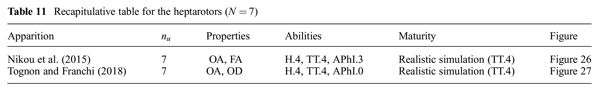
Recapitulative table for the heptarotors (
Arguably, heptarotor designs first appeared in Nikou et al. (2015), where an optimal design for a manipulation task with body-fixed end-effector was considered, see Figure 26. The unidirectional AAUs constraint is considered explicitly. The optimization considers the condition number of
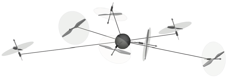
Conceptual three-dimensional kinematic representation of the heptarotor design presented in Nikou et al. (2015).
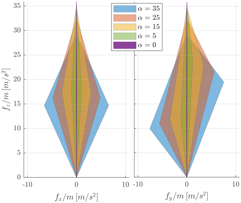
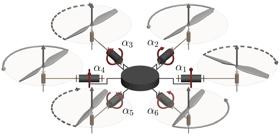
The optimization design problem in Tognon and Franchi (2018) assumes fixed positions of the AAUs, radially around the CoM, and optimizes their respective tilting. A major design criterion considered was a minimum allocation-matrix condition number, which aims at an equal sharing of the effort needed to generate wrenches in any direction. In addition, the notion of “balanced design” was introduced which guarantees an equal sharing of the extra effort needed to keep all AAUs’ individual thrust positive. An associated controller relying on model inversion and PID is proposed alongside. The general optimal design problem is proposed to make the design OD while minimizing the range of required control inputs to hover in any orientation. It is described and applied for
Conceptual three-dimensional kinematic representation of the heptarotor design presented in Tognon and Franchi (2018).
Visualization of the
10. Other designs with eight AAUs or more
We group all other platforms with
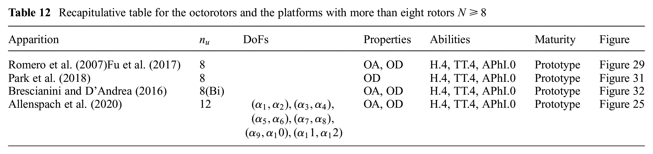
Recapitulative table for the octorotors and the platforms with more than eight rotors
The preference of the octorotor design over others in the literature can be explained by the favored symmetric multirotor design with an even number of propellers. Moreover, due to the required compactness of commercial platforms, it becomes important for the design to have the fewest propellers for the given application. A larger number of propellers adds more weight to the platform and requires a larger platform to avoid aerodynamic interactions between adjacent AAUs, and thus is only used when additional thrust is required.
10.1 Enhanced quadrotor design
Octorotor designs in this section can be seen as an attempt to overcome the translational under-actuation of coplanar/collinear quadrotors, by adding four AAUs with thrust oriented in the non-actuated directions, similarly to the pentarotor in Albers et al. (2010).
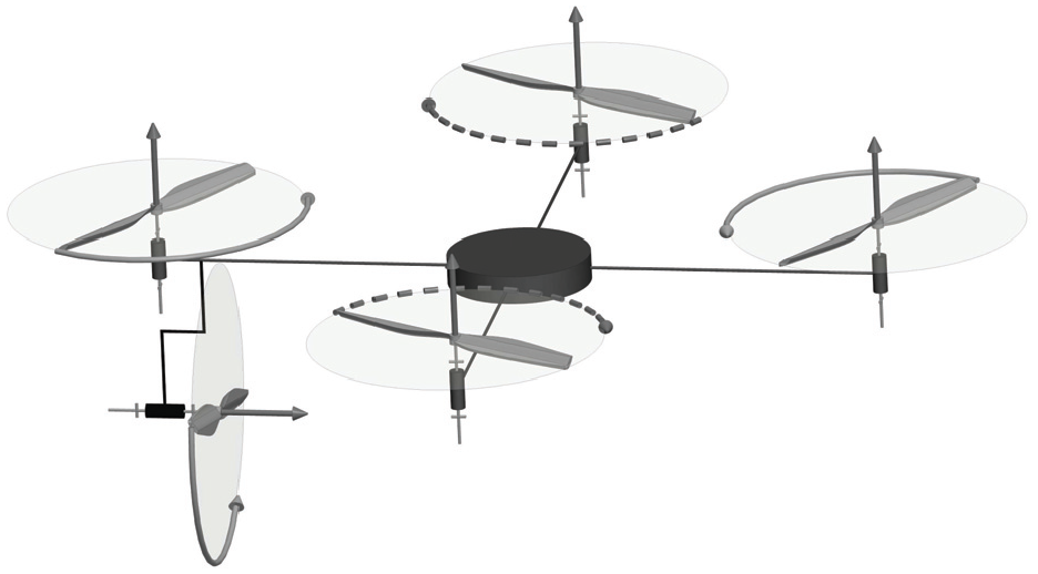
Romero et al. (2007) proposed a multirotor design based on a quadrotor design with four additional smaller AAUs, orthogonal to the four main ones. A conceptual kinematic design is shown in Figure 29. The extra AAUs are devoted to controlling the lateral motion of the multirotor. It is interesting to note that the lateral smaller propellers produce an airflow that perturbs the induced wind speed in the main propellers increasing its lift. This term is compensated by a feedforward linearization of the aerodynamics interaction to obtain a full decoupling between the rotational and translational movements. The trajectory tracking problem is then solved by resorting to a mixture of a model-independent PD controller, coupled with a model-dependent compensation of the Coriolis and gyroscopic non-linear torques. The
Conceptual three-dimensional kinematic representation of the octorotor design presented in Romero et al. (2007).
Visualization of the
In Fu et al. (2017), the AAUs are also tilted in the lateral plane but are located differently, reducing the cross-wind which improved the efficiency; this results again in an FA design.
10.2 Optimized octorotor designs
Following these basic octorotor designs, some more refined designs can be found in the literature.
Park et al. (2016, 2018) included aerodynamic interferences in the optimization problem. The goal of the optimization is to find an optimal wrench generation and an optimal rotor location within a maximum allowable volume. The first design was presented in Park et al. (2016) with
Conceptual three-dimensional kinematic representation of the octorotor design presented in Park et al. (2016, 2018)..
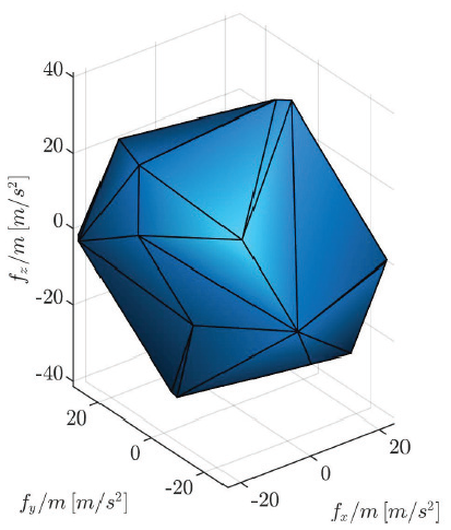
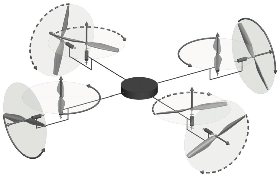
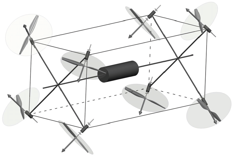
An optimized octorotor design with bidirectional propellers is presented in Brescianini and D’Andrea (2016) and shown in Figure 32. The platform is intended to be omnidirectional, and was designed by placing propellers on the edges of an octahedron to have a rotational invariant inertia tensor. Then the rotor disk orientations were chosen to maximize a measure of the platform’s agility, i.e., the norm of the maximum attainable force–torque in any direction. As the system is FA, the authors exploit the feedback linearization technique to derive the controller.
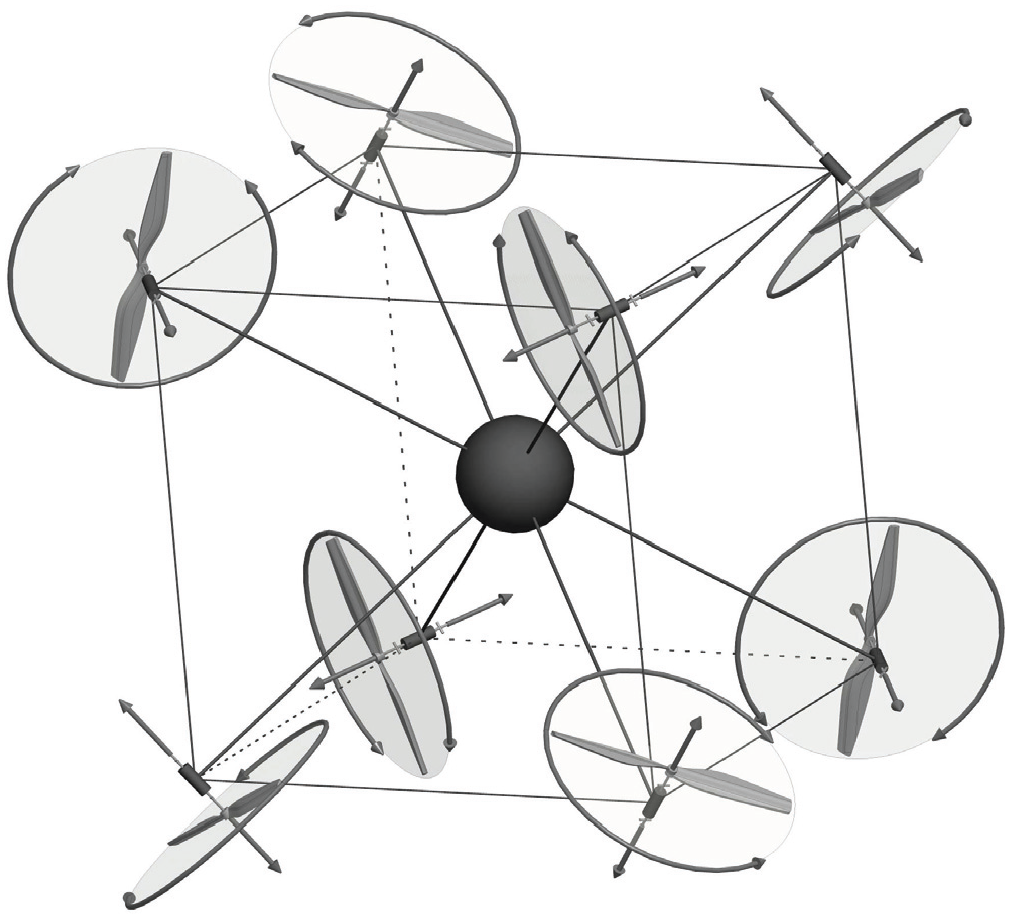
Conceptual three-dimensional kinematic representation of the OD octorotor design presented in Brescianini and D’Andrea (2016).
In the technical report attached to Tognon and Franchi (2018), which has been introduced in the previous section, an application for
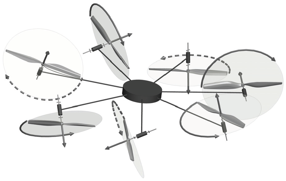
Finally, Allenspach et al. (2020) presented a dodecacopter that is an upgrade of the Voliro design presented in Kamel et al. (2018), where the platform is endowed with 12 propellers, mounted on 6 equally spaced arms in pairs, where each of these pairs share the same spinning axis and rotate in opposing directions. Each arm of the platform can rotate about its radial axis, and thus
11. Discussion
Throughout the review, we have realized a few patterns in the presented designs, such as: (1) the focus on symmetrical designs; (2) the use of unidirectional propellers; (3) ignoring aerodynamic interaction between propellers; (4) and, finally, system modeling not considering actuation limits.
While these patterns are prevalent, there has been some attempts in the literature to break these renditions. However, the full analysis of each, the corresponding advantages, and their incorporation in future designs is still to be done.
11.1 Platform symmetry
We can see that in the presented literature, the majority of designs enforce some symmetry assumptions. These symmetries vary from placing all propellers on a horizontal axis; assuming the same tilt for all propellers (with varying directions); assuming all propellers to be placed on a circumference around the geometric center of the platform, or finally having an even number of propellers. The symmetry is usually done to simplify the mechanical design and the resulting modeling and control, which in turn results in stable platforms and easy to mass-produce designs. However, we have seen that Tognon and Franchi (2018) by optimizing the tilt of the propellers about the horizontal axis, independently of any symmetry between the tilts, was able to achieve OD with
11.2 Bi-directional propellers
We realized throughout the review that the use of bidirectional propellers is scarce, where only a few of the cited designs (Brescianini and D’Andrea, 2016; De Martini et al., 2017; Park et al., 2016, 2018; Rashad et al., 2017) decided to use such propellers, in spite of the benefit of controlling the thrust produced by the propeller in both directions. One possible motivation is the “singular” behavior near the zero-thrust region (Park et al., 2018), where the propeller tends to take longer to reverse their direction of rotation (Brescianini and D’Andrea, 2016). Moreover, commercial solutions for reversible electronic speed control are scarce and the geometry of the propeller is less energy efficient than the unidirectional counterpart. Lastly, at low speed, the controllability of the exerted forces is very low, thus difficult to be used in practice. The variable pitch propeller can mitigate some of these issues but they come at the expense of additional mechanical complexity and weight, which is also not very practical. Another solution that can be achieved in this part is the use of bidirectional propellers while avoiding the allocation near the inversion zone of each propeller. However, proper optimization algorithms must be designed for this regards, in addition to the need for a redundancy resolution in the allocation capabilities.
11.3 Aerodynamic interaction between propellers
The field at large could benefit from further studies on the aerodynamic effects at play, especially the interplay between AAUs cross-wind. The integration of the aerodynamic effects in the model used for control synthesis should permit feed-forward cancellation of these effects. This is of particular importance for the development of platforms endowed with fine force interaction capabilities. In addition, a good model of the aerodynamic effects could be leveraged in the design process, extending Nikou et al. (2015) and Park et al. (2018), or benefiting from the work of Waslander and Wang (2009).
11.4 Actuator limits
Actuator saturation is often dismissed in theoretical studies but plays an important role in practice. Indeed, saturations hinder the multirotor dynamics, and if not taken into account properly, can result in destabilizing the control actions, in particular in dynamical maneuvers or while in physical interaction. While a few papers study the saturation’s effect on control (Franchi et al., 2018; Invernizzi and Lovera, 2017), we found only one work that incorporates the actuation limits in their design Jiang et al. (2017). In particular, Jiang et al. (2017) optimized propeller tilt angles of a tilted hexarotor (similar to Figure 21, top) to increase the possible platform lift while increasing the efficiency of the platform.
12. Conclusion
In this literature review of multirotor design, we first proposed a universal parametrization of multirotors in order to try to homogenize the vast literature on the topic. Based on this parametrization we first proposed a set of system properties and system capabilities for multirotors. Then we evaluated the vast literature on multirotor design and highlighted key conditions to reach certain properties. Finally, we grouped the reviewed designs into classes based on their number of AAUs as we found it more natural for the readers, and showed how designs from each class expanded the allocation capabilities of such class. To the best of the authors’ knowledge, this literature review is the first of its kind, and encompasses most of the relevant designs on the topic.
From this literature review and the proposed taxonomy, we could see that initial designs started as a method to upgrade a classical helicopter aircraft ( i.e., a birotor, with one variable pitch main rotor with a cyclic input on one axis, and one perpendicular in the tail), then either the design degenerated the platform to push the aerodynamics of the design to have flight with the fewest controls, or increased the number of actuators and changed their disposition about the CoM of the platform to achieve more stable platforms (quadrotors), or achieve higher levels of actuation (MDT, FA, OA, OD). Eventually, coplanar/collinear quadrotors became the base case for most designs thanks to their availability, stability, and the simplicity of their mechanical design.
The changes from classical designs entailed advantages in allocation and allowed the platforms to be able to interact with the environment, resist disturbances, apply lateral forces without a change in direction, and become robust to AAU failures. In our summary of each platform, we showed how each design corresponded to a specific set of abilities and properties. Recent platform designs started shifting more towards achieving omnidirectional flights, or decoupled force-moment allocation, preferred for physical aerial manipulation tasks, with this last application increasing in popularity thanks to the technological impact it entails.