
Abstract
We propose a novel framework of haptic rendering and interactive simulation, which, by exploiting midpoint time integration, that is known for its superior energy-conserving property but has not yet been adopted for haptics and interactive simulation, can enforce discrete-time passivity of the simulation effectively in practice, while retaining real-time interactivity due to its being non-iterative. We derive this passive midpoint integration (PMI) simulation for mechanical systems both in maximal coordinates (i.e. in SE(3)) and in generalized coordinates (i.e. in
Keywords
1. Introduction
With many research groups and companies around the world aiming their efforts at blurring the boundary between the real world and virtual worlds in the form of, for example, virtual reality, augmented reality, mixed reality, and so on, providing realistic and believable artificial visual, auditory, olfactory, and mechanical experiences to users in real time is now increasingly in demand. Among these modalities, the artificial mechanical experience, or haptic experience, possesses its own peculiar challenges. Specifically, as compared to other virtual sensory modalities, it requires a much faster update rate while being under more stringent requirements for stability within the virtual world or with the human users.
Numerous strong results and methodologies have been proposed for realizing this virtual mechanical experience by different research communities. On the one hand, in the field of haptics, it is pursued under the name haptic rendering, for which some avatar of the haptic device (e.g. god-object (Zilles and Salisbury, 1995), virtual proxy (Colgate et al., 1995; Lee et al., 2012)) and the virtual objects are simulated together, typically at a rather fast speed (e.g. 500 Hz to 1 kHz), with their complexity encompassing the simplest one-dimensional virtual wall (e.g. Colgate and Schenkel, 1997; Lee and Huang, 2008) to complex deformable objects such as human organs (e.g. Delingette, 1998; Duriez et al., 2006; Garre and Otaduy, 2010). On the other hand, in the field of computer animation (Baraff, 1996; Garre et al., 2011;Müller et al., 2005; Weinstein et al., 2006), it is often called by the name interactive simulation, which typically deals with virtual objects and entities more complex than those of haptic rendering, with a slower update rate (e.g. 10 Hz to 50 Hz), which is still fast enough for users to interact in real time. By utilizing a multi-rate interface (e.g. Duriez et al., 2006; Fotoohi et al., 2007; Lee and Huang, 2010), it is also possible to combine the interactive simulation with haptic rendering.
The core of any frameworks in haptic rendering and interactive simulation of dynamical systems * is the time integration, and the majority of state-of-the-art frameworks adopt symplectic Euler integration (SEI (Hairer et al., 2006), also often referred to as the semi-implicit Euler method in the field of haptics and computer animation: see e.g., Cline and Pai, 2003; Müller et al., 2005; Weinstein et al., 2006) or implicit Euler integration (IEI: e.g., Courtecuisse et al., 2015; Duriez et al., 2006; Otaduy and Lin, 2006; Otaduy et al., 2009). Widely used commercial physics engines and interactive simulation tools also rely on SEI (e.g. CHAI-3D 1 based on ODE, 2 and VREP 3 based on ODE or Bullet 4 ). Implicit Euler integration, in its exact form, is known to be (strictly) stable (e.g. Chung and Hulbert, 1993; Hairer et al., 2006), allowing for a wide range of parameters (e.g. lighter mass with stiffer spring for transparency) and a longer integration interval (i.e. faster simulation), yet is typically implemented only approximately for interactively-fast running (e.g. linearization (Duriez et al., 2006; Otaduy and Lin, 2006), explicitization (Krysl, 2005, 2006)). This IEI is also in general strictly dissipative, and thus cannot simulate lossless or energy-conserving behavior (e.g. vibrating flexible objects). The SEI is usually simpler to implement (and thus faster) than the IEI due to its semi-implicit nature. This SEI, however, is known to be only conditionally stable (e.g. Hairer et al., 2006), which is fairly detrimental in practice, as one cannot freely tune and explore parameters of virtual objects to achieve (possibly changing) target performance independently from other parts of the virtual world.
On the other hand, passivity has been one of the most powerful tools in the fields of haptics, telerobotics and interactive robotics for enforcing stability among dynamic_ entities coupled via feedback interconnection between, for example, robots and humans, robots and robots, robots and the environment (Buerger and Hogan, 2007; Colgate and Schenkel, 1997; Lee and Huang, 2010; Lee and Li, 2005; Lee and Spong, 2006). This passivity is particularly desirable for haptic rendering and interactive simulation, since, as pointed out in Brown and Colgate (1998), it allows for (1) stable simulation with any parameters and update rate (e.g. arbitrarily light/stiff simulation with coarse integration intervals), and (2) modular construction of provably stable virtual worlds by simply combining individual virtual objects, each designed to be passive. Information delays among virtual objects or virtual worlds can also be addressed in a straightforward manner using this passivity formalism (e.g. for multi-user haptics; Huang and Lee, 2013; Rakhsha and Constantinescu, 2014).
In this paper, we propose a novel passivity-based framework of haptic rendering and interactive simulation. The key differentiating and innovative aspect of our framework is our adoption of the midpoint time integration, whose energy-conservation ability is well known in the field of structural mechanics (e.g. Bathe, 2007; Chung and Hulbert, 1993; Krysl, 2005, 2006; Kuhl and Crisfield, 1999; Simo and Wong, 1991; Simo et al., 1992), but which, to the best of our knowledge, has not been adopted so far for haptic rendering and interactive simulation. This missing of the midpoint integration is particularly surprising for the case of haptic rendering, as its energy-conserving property naturally suggests the possibility of discrete-time (lossless) passive simulation, which was proposed as one of the ultimate goals of haptic rendering in Brown and Colgate (1997, 1998), yet, has been dodging so far any attempts to attain that. Of course, this energy-conserving property is only for a single system, and the passivity property, which is concerned with their interconnection with other objects via power-conjugate input–output mapping, has not been studied in the field of structural mechanics. It was however independently shown in Lee and Huang (2008) and Lee et al. (2012) that, by directly enforcing passivity in the discrete-time domain in a manner similar to that for the derivation of variational integrators (e.g. Marsden and West, 2001), it is indeed possible to develop a passive integrator, which is called the non-iterative passive mechanical integrator (NPMI) and which turns out to be a midpoint integrator. This NPMI was derived in Lee and Huang (2008) and Lee et al. (2012), however, it is limited to only mechanical systems which are linear or written in generalized coordinates with no intermittent and unilateral contact with other objects. Recently, we extended this NPMI for mechanical systems in maximal coordinates with a linear complementarity problem (LCP) formulation of Coulomb friction contact (Kim et al., 2017).
In this paper, we unify and generalize these NPMI-related results by Lee and Huang (2008), Lee et al. (2012), and Kim et al. (2017) as a midpoint integration framework which can deal with linear and nonlinear mechanical systems expressed both in generalized and maximal coordinates under unilateral/intermittent multi-point Coulomb friction contacts formulated via LCP, all the while effectively enforcing discrete-time passivity of the simulation and also its real-time interactivity by preserving the non-iterative nature of the NPMI. Some approximations, inevitable in rendering the algorithms interactively fast, are also adopted here, as in most other haptic rendering and interactive simulation results (e.g. Cline and Pai, 2003; Courtecuisse et al., 2015; Duriez et al., 2006; Krysl, 2005, 2006; Müller et al., 2005; Otaduy and Lin, 2006; Otaduy et al., 2009; Weinstein et al., 2006). Even so, our proposed algorithms can still exhibit fairly passive behavior, as demonstrated by our validating simulation examples (see Section 5) and also as similarly concluded in Krysl (2005, 2006) for midpoint integration with some approximations. For this reason, we call our integrator a passive midpoint integrator (PMI) and our framework, the PMI-based haptic rendering and interactive simulation.
Due to its passivity enforcement and implementation flexibility, our proposed PMI-based framework possesses the following advantages.
It can stably simulate mechanical objects with a wide range of parameters (e.g. any positive-definite mass, stiffness and damping gains, and varying update rate possible), thereby allowing for easy and modular tuning of virtual objects while also providing the capacity to adjust the discrete-time damping dissipation necessary to render the simulation more or less stable depending on the target performance and behavior.
Consequently, it can simulate very light/stiff objects, which is desired for sharper/transparent haptic rendering (see the peg-in-hole simulation in Section 5.1) or necessary to simulate some classes of mechanical systems (e.g. an under-actuated tendon-driven (UATD) hand with light fingers and stiff tendons; see Section 5.3), but typically cannot be stably rendered by (conditionally stable) SEI-based frameworks (e.g. CHAI-3D).
It can simulate marginally stable/energy-conserving behavior such as the vibration of flexible objects (see Section 5.2 and also Section 2.3) or elastic contact between two rigid objects with no extra restitution models (see Section 3.3), which typically cannot be achieved by dissipative/decaying IEI-based frameworks, with its implementation complexity at least comparable to that of IEI.
It allows us to use both the maximal and generalized coordinates and even their combination, substantially streamlining the simulation of some mechanical systems such as the UATD hand composed of fingers with tendon routing and a rigid body palm (see Section 5.3) or the flexible beam with a rigid plate connected to haptic devices (see Section 5.2), which, so far, are not so readily integrated in CHAI-3D or VREP.
To our knowledge, this paper provides a solution for the first time to the long-standing problem posed in Brown and Colgate (1997, 1998) of how to attain passivity and interactivity of simulation at the same time.
The rest of the paper is organized as follows. Section 2 contains some preliminary materials, including the definition of passivity, the kinematics and dynamics of rigid bodies in SE(3) and robots, and a summary of the NPMI development for linear mechanical systems in Lee and Huang (2008). We then derive the PMI-based simulation framework in maximal coordinates in Section 3 and in the generalized coordinates in Section 4 with the PMI-LCP formulation of Coulomb friction point contact modeling for each setting. Illustrative examples, namely a peg-in-hole task, flexible beam haptic interaction and UATD hand grasping, are presented in Section 5 to validate and demonstrate our PMI-based framework. A summary and some comments on future research directions are then given in Section 6.
2. Preliminary materials
2.1. Mechanical systems and passivity
The virtual worlds we aim to construct in this paper are mainly composed of multiple articulated rigid bodies (Weinstein et al., 2006) with some constraints (e.g. no penetration, rotation/pivot joints, etc.), elastic elements (e.g. springs), viscous damping elements, and Coulomb friction between them. A part of these mechanical objects is typically interfaced with some human commanding device (e.g. a haptic device), which will not be discussed here in detail; instead, we refer readers to prior results on the (possibly multi-rate) virtual coupling applicable to our PMI simulation (e.g. Huang and Lee, 2011; Lee and Huang, 2010; Lee et al., 2012) and also to Section 5 for some application examples. Large-scale deformable objects (e.g. human organs; Delingette, 1998) are not the main concern of this paper either and we leave them and their salient issues (e.g. model reduction, fast contact resolution, large deformation, St Venant tensor simulation, etc.) for future publications, although the PMI framework is equally applicable to them as well (e.g. Huang and Lee, 2013).
There are two ways to describe such articulated multiple rigid bodies: (1) maximal coordinates, which is the SE(3) rigid body transformation of each rigid body with the relative motion constraints implemented by Lagrange multipliers or through some other means (e.g. Hadap, 2006; Weinstein et al., 2006); and (2) generalized coordinates, which are obtained by reducing the degree of freedom (DOF) of the total system by applying their relative motion constraints (e.g. Lee et al., 2012; Spong et al., 2006). The maximal coordinate approach is typically preferred for simulating complex systems (e.g. systems composed of a large number of rigid bodies with possible collisions among them), whereas the generalized coordinate approach is more convenient or imperative for some mechanical systems (e.g. flexible beams with nodal coordinates, rigid links with elastic tendon routing, etc). The rendering framework proposed in this paper allows for both maximal and generalized coordinates as well as their combination (see Section 5.2 and Section 5.3).
More specifically, the maximal coordinate approach simulates the articulated multiple rigid bodies as a combination of their constituent single rigid body, whose dynamics in SE(3) can be written using the following Newton–Euler dynamics:


where
On the other hand, the dynamics of articulated rigid bodies in generalized coordinates can be written using the following continuous-time nonlinear Lagrangian dynamics:

where
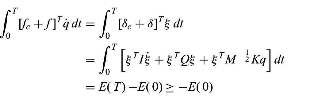
It is then well known that the mechanical system represented by maximal coordinates (1)–(3) or by generalized coordinates (4) satisfies the (continuous-time) passivity (Spong et al., 2006)
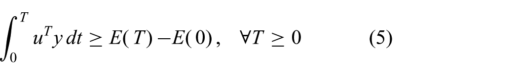
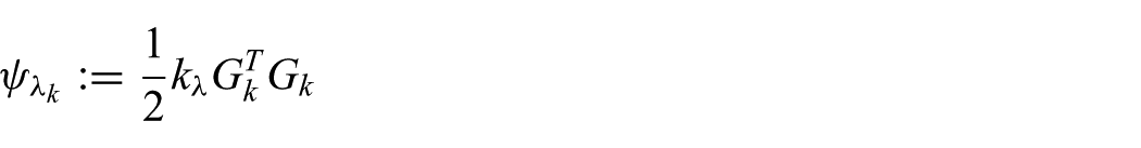
with
Further, from the passivity theorem (Vidyasagar, 1993) that the feedback interconnection of any passive systems is necessarily stable regardless of their parameters (with some detectability condition met), this also implies that, if we can simulate each virtual entity to be passive, we may then construct very a complex virtual world simply by combining those passive virtual entities, each of which can be designed individually without referring to other components and whose parameters can be set arbitrarily as long as passivity is preserved (e.g. any positive-definite
This (fundamental) continuous-time passivity (5) is in general not yet easily achievable in the discrete-time domain, particularly when the simulation speed needs to be haptically fast. In fact, the work of Brown and Colgate (1998) shows that no explicit discrete-time passive integrators exist. To address this, in Lee and Huang (2008) we proposed a new integrator, NPMI, which is implicit, yet requires no iterations, and thus can still be solved haptically fast while also enforcing discrete-time passivity. This NPMI turns out to be a midpoint integrator, and is to be generalized in this paper to be a PMI. In Section 2.2, we summarize the result of Lee and Huang (2008), which stands as the backbone of the ensuing development of the PMI-based haptic rendering and interactive simulation framework of this paper.
2.2. Review of NPMI for linear mechanical systems
To introduce the main idea of NPMI (Lee and Huang, 2008), let us consider the following simple scalar linear mass–damper–spring dynamics:

where
where
where we also use
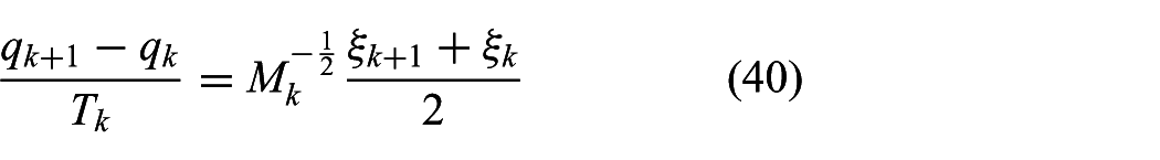
Our goal here is then to find a discrete-time integrator map

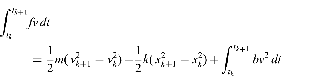
and the representative power variables

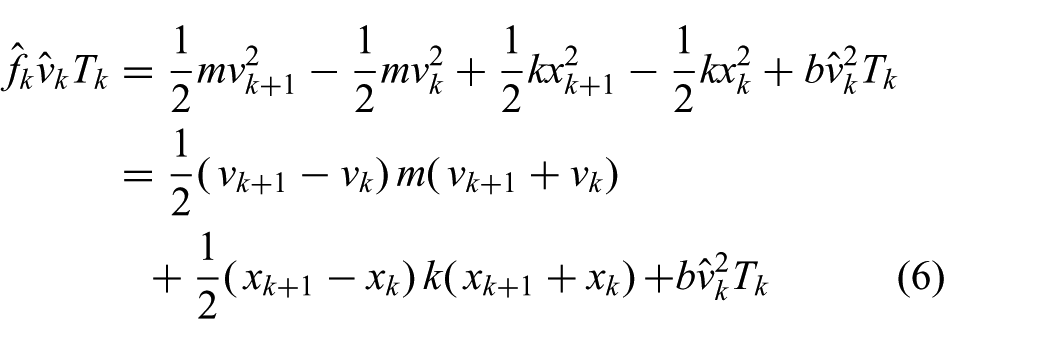
By comparing (6) with (7), the NPMI then suggests the following kinematics relation (Lee and Huang, 2008):
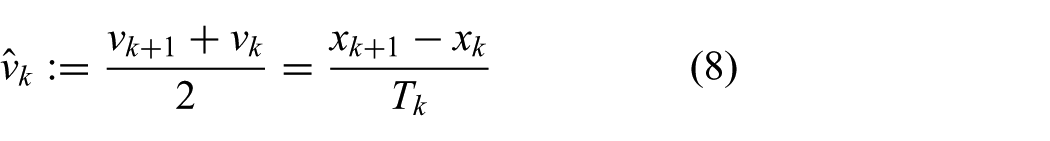
and, further, applying (8) to (6) and comparing with (7), it also suggests the following dynamics update equation:
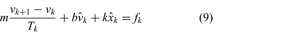
with
This NPMI (8)–(9) then exactly duplicates the continuous-time passivity property (5) by using the “representative” velocity
This NPMI (8)–(9) also turns out to be a midpoint integrator (e.g. Bathe, 2007; Krysl, 2005, 2006; Kuhl and Crisfield, 1999; Simo et al., 1992), which is well known for its superior energy-conserving property (i.e. passivity, but with no input–output consideration) in the structural mechanics community, but has not been adopted so far for haptic rendering and interactive simulation. In this paper, we generalize this NPMI as a PMI, with full consideration of input–output mapping (i.e. power port), generalized and maximal coordinate formalisms, nonlinear dynamics (1)–(4), and constraints and multi-point contacts with Coulomb friction, all the while retaining its discrete-time passivity and non-iterativeness by utilizing certain coordinate transformations and potential action approximation.
Of course, other types of integrators have also been used for haptic rendering and interactive simulation, namely, explicit Euler integrators (EEIs), symplectic Euler integrators (SEIs), and implicit Euler integrators (IEIs), with the second being adopted for the majority of widely used open physics engines (e.g. Bullet and ODE, with VREP and CHAI-3D built upon them). In Section 2.3, we perform a simple yet effective comparison study among EEI, SEI, IEI and PMI.
2.3. Comparison of EEI, SEI, IEI and PMI
Consider the simple scalar linear mass–spring system, which can be written as
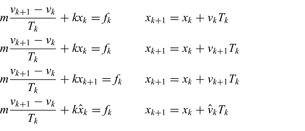
presented in the order EEI, SEI, IEI and PMI, where
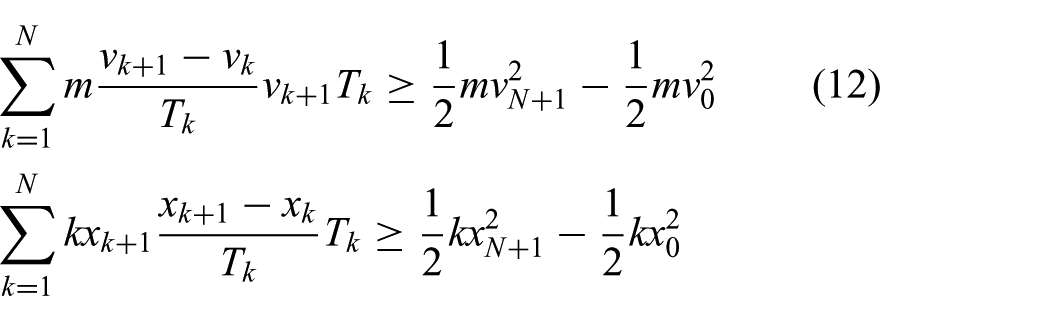
Then, adopting a procedure similar to that in Section 2.2, we can obtain the passivity property of each integrator as follows. First, for the EEI, we have

for which we utilize
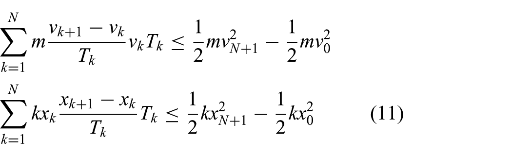
derived by using the Cauchy–Schwarz inequality. This then implies that EEI is in general not passive. Similarly, for the IEI, we have
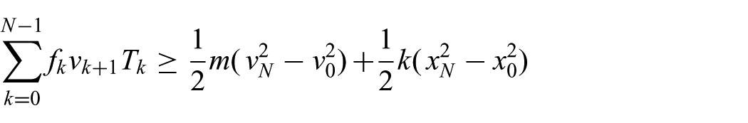
for which we utilize
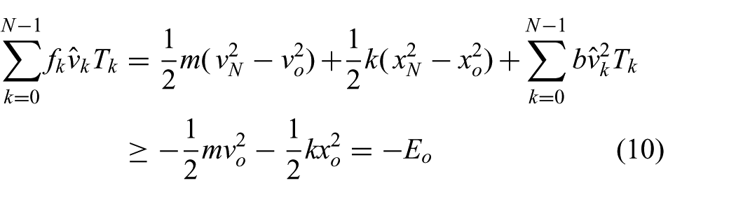
This then implies that IEI is passive, but in general dissipative, and thus not able to simulate lossless behavior such as harmonic oscillation. On the other hand, for SEI, its passivity is undetermined, since its relation is a combination of (12) (i.e. passive) and (11) (i.e. non-passive). This in fact matches well with the known fact that SEI is only conditionally stable depending on parameters. Finally, for PMI, we have
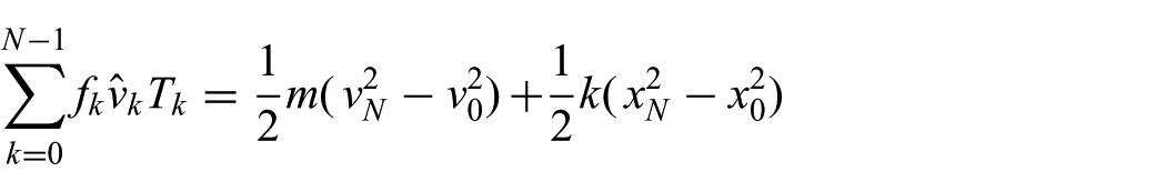
from (10), implying that it is passive, and, furthermore, exactly lossless, and thus can precisely simulate harmonic oscillation.
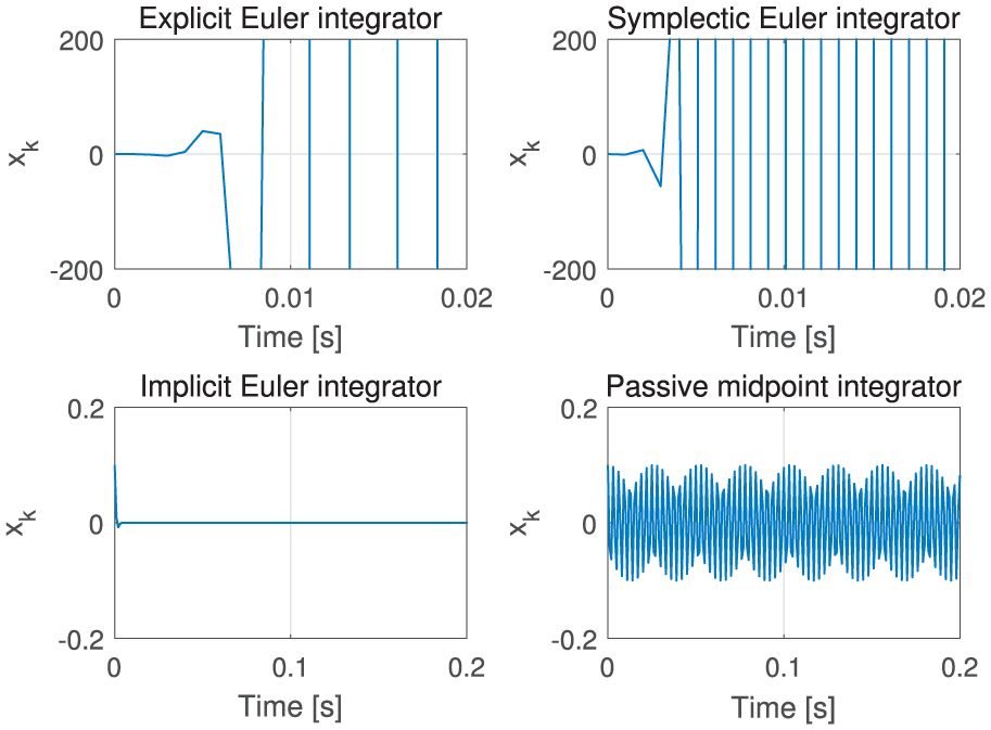
This observation is then confirmed by the simulation results in Figure 1 and Figure 2, where (1) the EEI always diverges; (2) the SEI can simulate harmonic oscillation with large mass, yet diverges with small mass; (3) the IEI always converges to zero, yet is not able to sustain harmonic oscillation, clearly showing its dissipativeness; and (4) only the PMI can simulate harmonic oscillation with the total energy exactly conserved for any mass/spring ratio. This then clearly shows the advantage of our PMI, namely its usability for passive (i.e. stable) simulation with a wide range of parameters as compared to EEI and SEI, while also being typically simpler to implement than IEI on top of its ability to simulate lossless behavior.
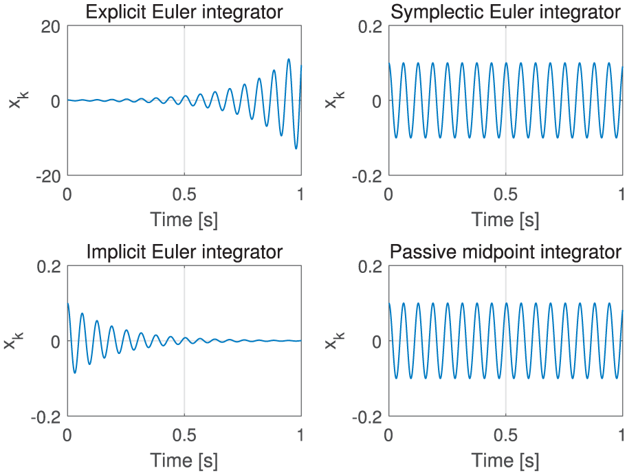
Simple harmonic oscillation simulation with EEI, SEI, IEI and PMI:
Simple harmonic oscillation simulation with EEI, SEI, IEI and PMI:
3. PMI-based simulation in maximal coordinates
The NPMI (8)–(9) of Section 2.2 exactly enforces passivity only for linear mechanical systems. Here, we generalize this NPMI to PMI of rigid bodies in SE(3), which constitute the basic building block of the maximal coordinate formalism of articulated rigid bodies. We also show how to incorporate constraints into this PMI-based simulation of rigid bodies to realize articulation among the rigid bodies, and how to include multi-point Coulomb friction contact via LCP formulation into the framework of PMI. The main complication with this is that the configuration space of rigid bodies in maximal coordinates is SE(3), which is not a vector space. The multi-point contact computation problem is also typically complex and time-consuming. To circumvent these challenges, here we utilize some approximations in enforcing passivity. Such approximation is in general necessary for other haptic rendering or interactive simulation results to attain interactivity (e.g. contact force linearization with IEI or SEI; Otaduy and Lin, 2006) or for structural dynamics to speed up the computation (e.g. interaction explicitation; Bathe, 2007; Krysl, 2005, 2006), which is known to work adequately in most cases, as confirmed through our experiments as well (see Section 5).
3.1. PMI of rigid body in SE(3)
Consider the Newton–Euler dynamics (1)–(3) of rigid bodies in SE(3). In this section, we derive the PMI formulation of (1)–(3). For this, we consider only the inertial dynamics (i.e. associated with
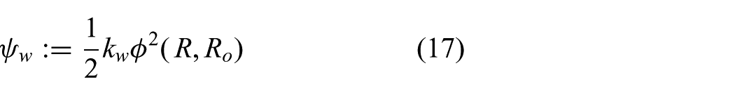
Then, with the linear spring potential
with the “representative” angular velocity
similar to (8). It is then not difficult to show the following passivity (lossless) property with
where we use
One thing still missing here is how to connect the angular velocity

where
with

where
This
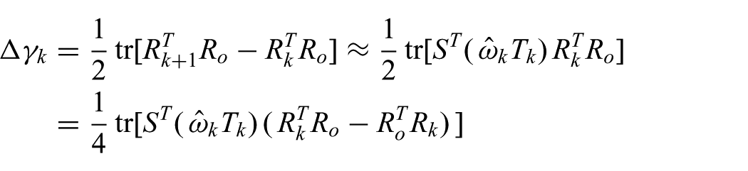
Our objective is then to find the action
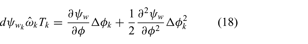
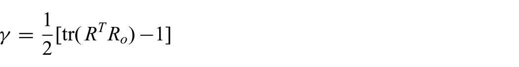
which is the second-order approximation of the exact potential difference (i.e.
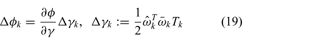
where

which has the direction of the equivalent axis between
which is reduced to (19), where we use (16), the first-order approximation of
Applying these to (18), we can then define
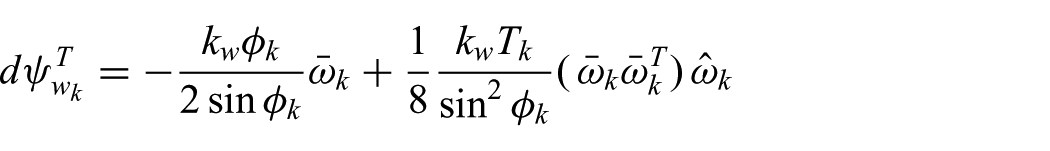
where
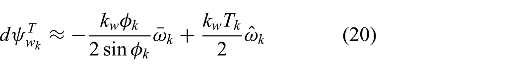
Note that the second term acts similarly to viscous damping action. The passivity of this SO(3) spring action (20) is then demonstrated in Figure 3, where stable sustained oscillation is attained with the total energy almost precisely preserved even if the action (20) is designed to enforce passivity only approximately.
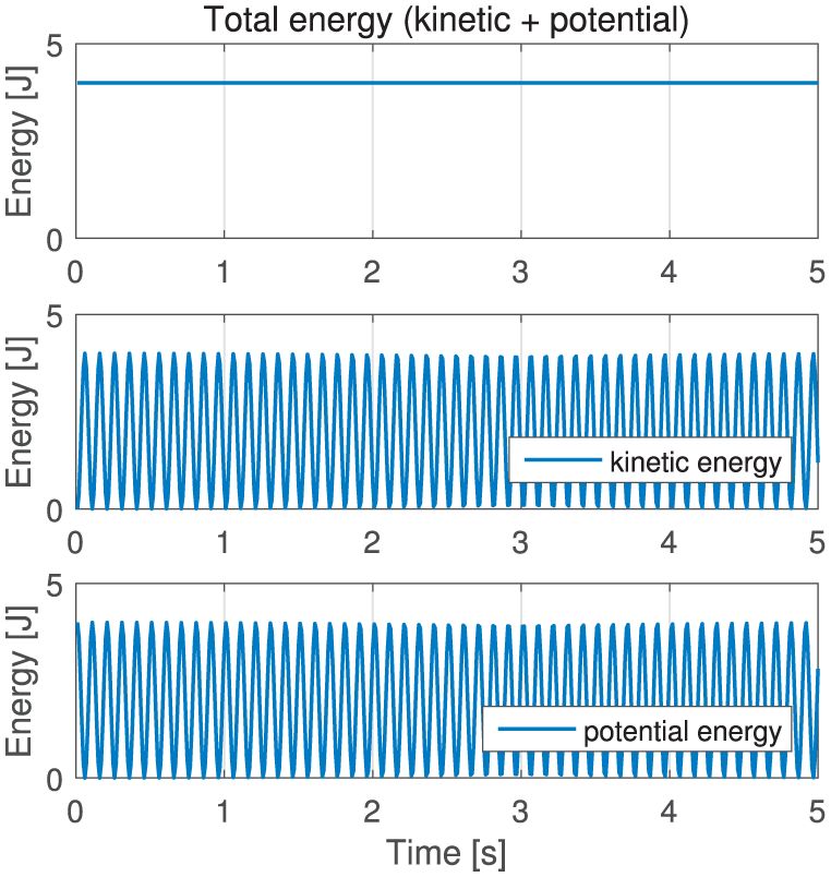
Total energy of rotational dynamics (13) with SO(3) spring (20) with nearly perfect energy conservation and stable/sustained oscillation in SO(3): with
Finally, the PMI expression of the Newton–Euler dynamics (1)–(2) with the linear spring for x and the SO(3) spring potential (20) can be written in one single equation:
where

where
3.2. PMI-based rendering of articulated rigid bodies
Some of the most widely used entities in haptic rendering and interactive simulation are so-called articulated rigid bodies (e.g. Weinstein et al., 2006). Here, we propose to construct such articulated rigid bodies as a collection of multiple rigid links with their joints implemented by constraining the positions of some points on successive links via very stiff springs. For instance, see the multi-fingered hand in Figure 4, where the distal interphalangeal (DIP) and metacarpophalangeal (MCP) joints of the index finger are implemented by enforcing two-point position constraints on the distal-middle and middle-proximal phalanges, whereas the thumb carpometacarpal (CMC) joint is implemented by one single-point position constraint between the palm and the metacarpal bone. Other types of joint constraints can also be implemented in a similar manner by using different spring potentials (e.g. elliptic joint with four-point springs (Knoop et al., 2005); prismatic joint with an SO(3) potential and a two-directional translation spring potential, etc.), details of which will be reported in future publications.
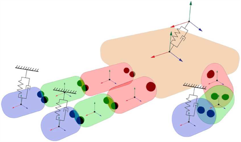
Multi-fingered hand rendered as articulated multiple rigid bodies with joints implemented by point constraint springs.
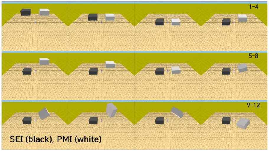
Snapshots of rigid box falling on rigid level surface: it bounces back and forth under PMI-LCP (white box), but completely plastically collides under SEI (black box) even with the same parameter settings.
Consider m rigid links with l point position constraints (e.g. m=10 and l=16 for the hand in Figure 4). We assume each of these l points is shared only by two successive links, although the development presented here can easily be extended to more general cases. Then, we can define the following map:

in other words, connecting the i th position constraining point (
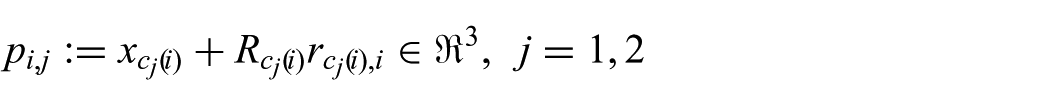
which is on the
To implement the joints among the m links, we then want to enforce

Stacking up all the l point position constraints, define the constraint function

with

where
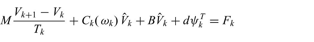
The PMI expression of the dynamics of the m rigid links with the l constraints can then be written similarly to (21):

where
where
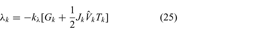
Then, using (10), (15), (18), (22) and (23), we can obtain
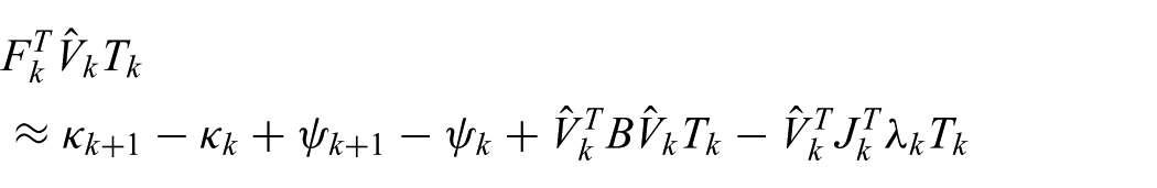
where
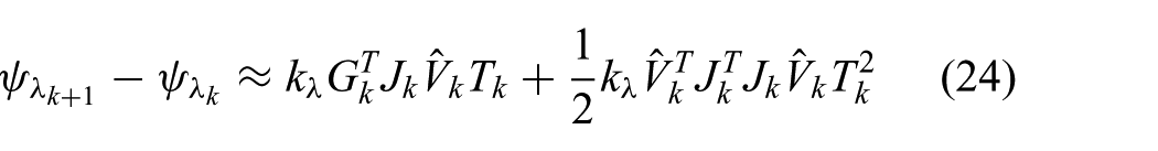
we can design
with which the above relation reduces to the following: with B=0,

where
The analysis above shows that the potential action
This passive enforcing of the constraint
3.3. PMI-LCP for multi-point Coulomb friction contact
The contact problem has been one of the key problems in computer graphics, structural mechanics, and haptic rendering. For this, there are two main directions of research, namely the constraint-based method (e.g. Duriez et al., 2006; Peterlik et al., 2011) and the penalty-based method (e.g. Drumwright, 2008; Kolesnikov and Zefran, 2007). The penalty-based method generates repulsive elastic force when two objects overlap with each other. This method is simple and easy to implement, but it has inherent limitations: allowing violation of the contact constraint (e.g. penetration). It is in general not straightforward either to implement Coulomb friction force with this penalty-based method. On the other hand, the constraint-based method directly calculates contact force, which is necessary for satisfying the contact constraint. By doing so, this method prevents violation of the constraint (to the extent of collision detection error and numerical precision error though, which can induce constraint drift). Friction generation is also more convenient with the constraint-based method.
To render the contact among rigid objects, we adopt the point contact model with Coulomb friction. Consider a contact point between two colliding rigid bodies. We can then define the contact normal direction

with the non-negative signs allowing only for separation or maintaining the contact. In this paper, we use the velocity-level constraint, which can then be written as the following complementarity condition (Siciliano and Khatib, 2008):

where
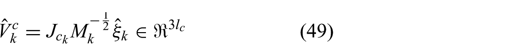
Now, suppose that the articulated rigid bodies (23) interact with another virtual rigid object, and denote the i th contact point from that contact by

which is on the
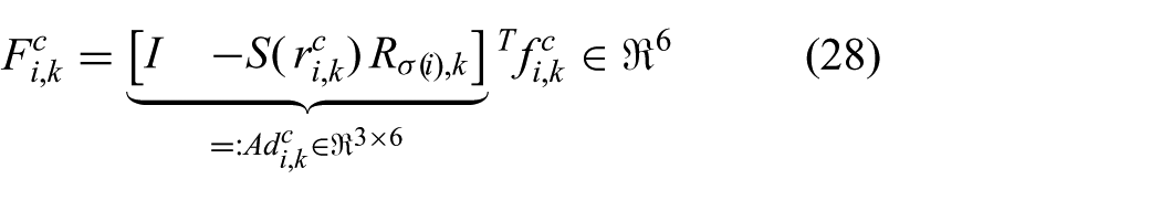
where
where
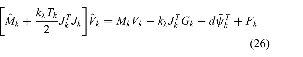
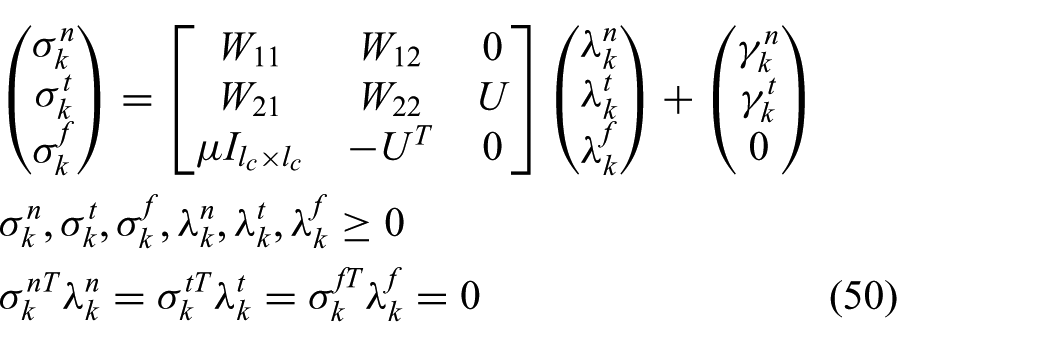
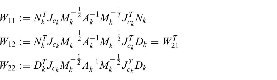
The PMI expression of the articulated rigid bodies, the virtual object, and their contact interaction can then be obtained by augmenting (26):
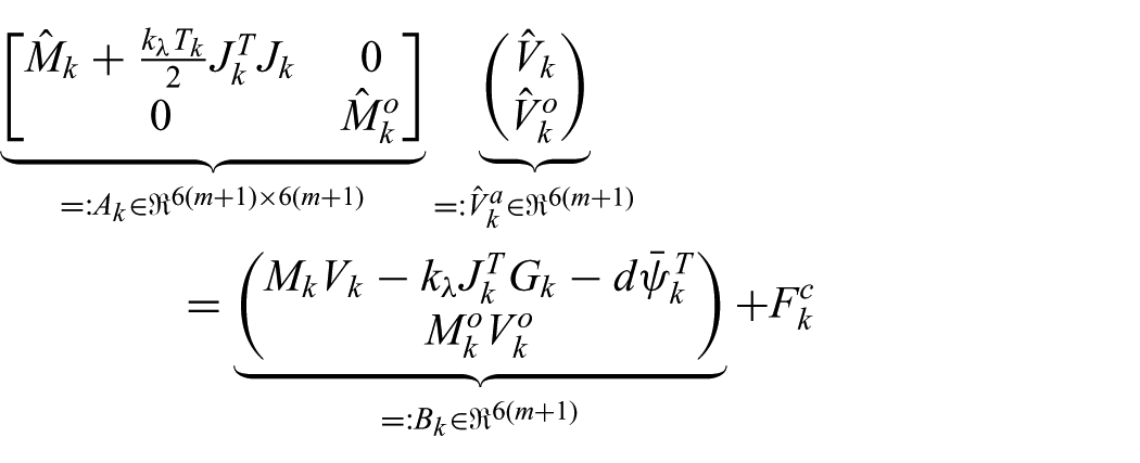
with the contact force term

where

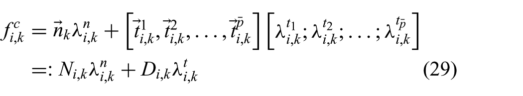
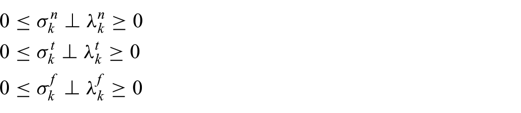
Similar to (27), here we adopt the velocity-level constraint. We can then write the following complementarity conditions (Lloyd, 2005):


where
with
where
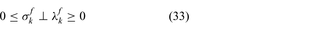
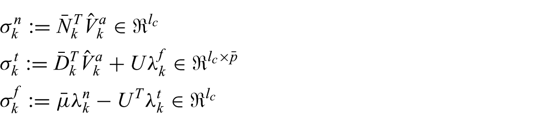
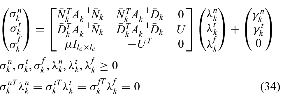
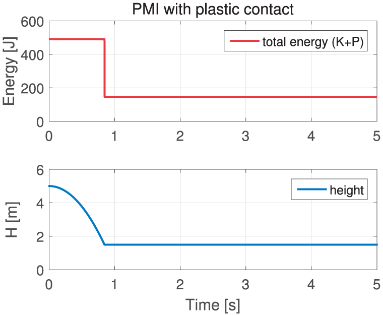
The complementarity conditions (31) to (33) naturally suggest passivity of our contact PMI-LCP formulation (34), that is, it is lossless if no tangential slip occurs, or dissipative if it does occur. This passivity of PMI-LCP (34) is clearly exhibited in Figure 6, where a rigid box free-falls on a rigid level surface and bounces back and forth, with the total energy being constant during the flight stages, but strictly decreasing during the contact stages, during which dissipative tangential slips occur. Note that this simulates lossless (i.e. elastic) collision along the normal direction and dissipative slips along the tangential directions, with no deformation allowed between the two rigid objects. With no slips, this would result in completely lossless/elastic collision.
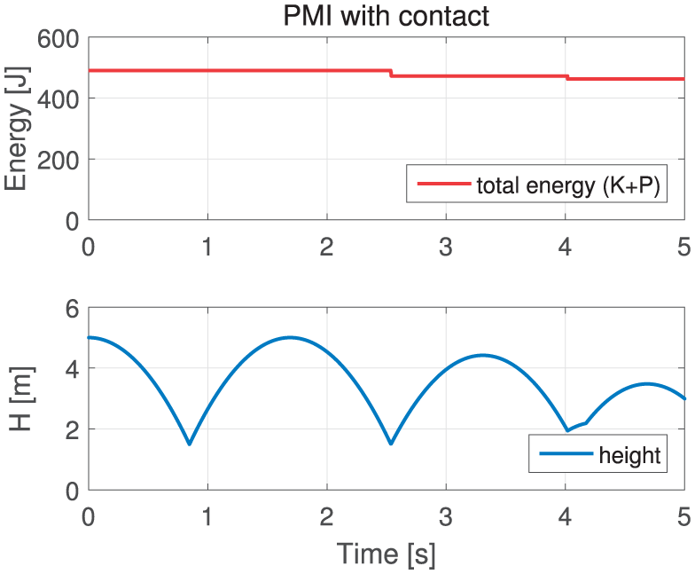
Profiles of total energy and height with PMI-LCP (34): elastic–normal and dissipative–tangential slip contact attained with total energy remaining constant during flight, but strictly decreased during contact. Sudden changes of H around 4 s to 4.2 s are due to collision with flipping.
This ability of our PMI-LCP (34) to naturally render (marginally stable) elastic contact is in stark contrast to other contact rendering results based on IEI or SEI, which typically can only produce plastic contact unless some extra velocity restitution models are deployed. This is in fact due to the adoption of

Profiles of total energy and height under PMI-LCP (34) with
Here, note that, in contrast to Section 3.2 (i.e. approximate passivity of
4. PMI-based simulation in generalized coordinates
In this section, we derive the PMI of the Lagrange dynamics (4) in generalized coordinates. We first show that the PMI formulations developed in Section 2.2 and Section 3.1 are not able to enforce passivity for the Lagrange dynamics (4) due to the nonlinearity of the dynamics. To overcome this, we propose a certain coordinate transformation, with which the nonlinear Lagrange dynamics (4) can be converted into a form compatible with the PMI formalism to enforce passivity in the discrete-time domain. We further show how to derive the PMI-LCP formulation in generalized coordinates for the Lagrange dynamics (4) to simulate point Coulomb friction contact, as done in Section 3.3 for the PMI in maximal coordinates.
4.1. PMI of Lagrange dynamics
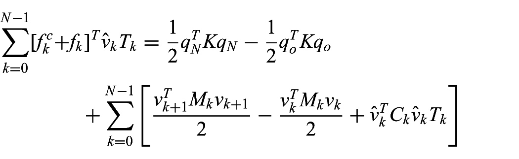
Consider the multi-DOF nonlinear Lagrange dynamics (4) with the generalized coordinates
Now, suppose M(q) in (4) be constant (i.e.
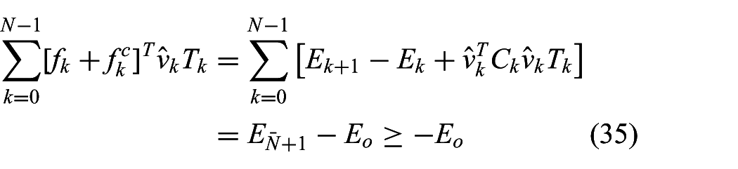
where
This discrete-time passivity (35), however, is not granted for non-constant M. That is, from M(q) being configuration-dependent, we have
where, differently from (35), the kinetic energies in the brackets do not cancel each other out over the successive
More precisely, define the following (continuous-time) coordinate transformation:
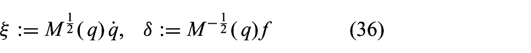
with which the kinetic energy can be written as
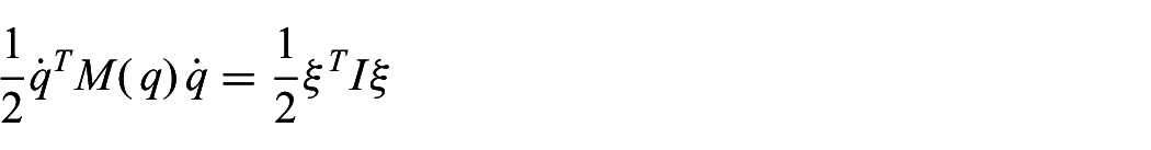
where
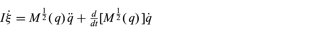
we can then rewrite (4):
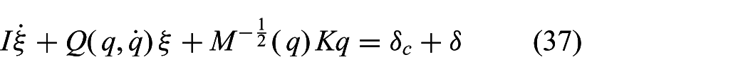
where the Coriolis-like term
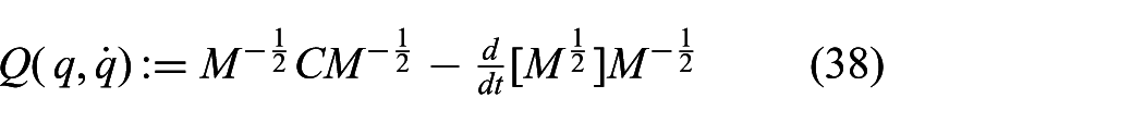
with arguments omitted for brevity.
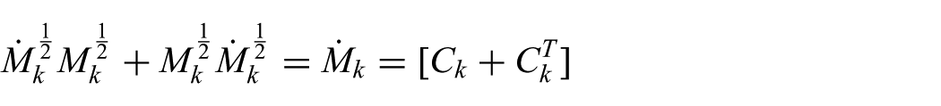
This matrix Q in (38) is in fact skew-symmetric. That is, with M being symmetric, we have
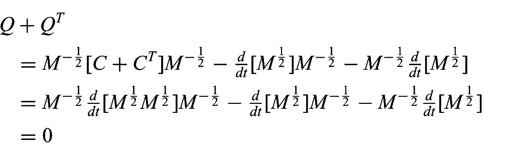
where we use the fact that
where
Since the transformed dynamics (37) has constant inertia I and skew-symmetric Q, we can now passively simulate (37) similarly to (9) and (13):
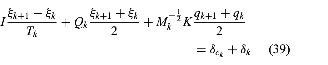
where
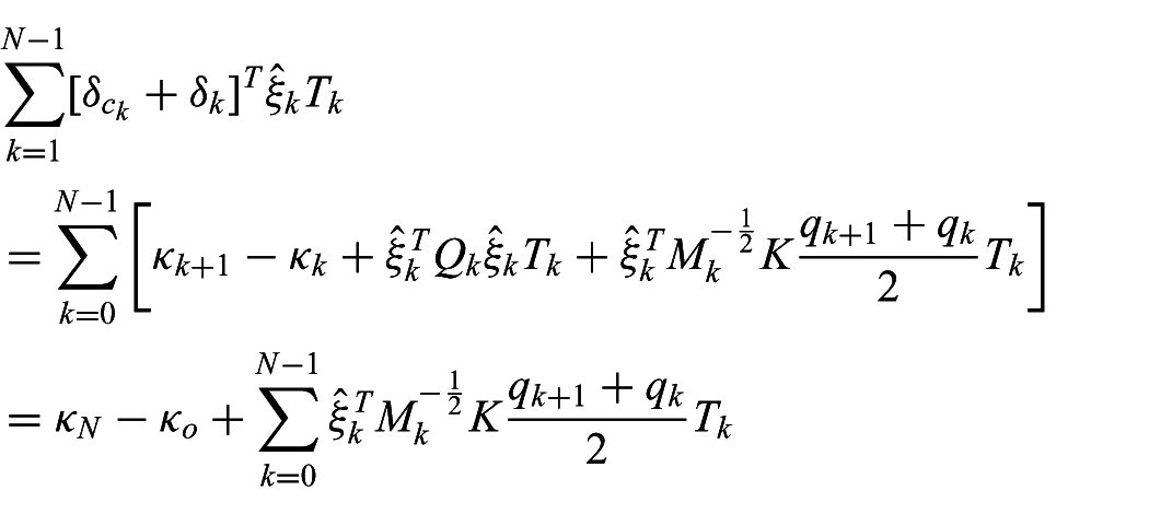
where
which is indeed consistent with the continuous-time transformation (36).
Note that, given the continuous-time Lagrangian dynamics (4), we first transform it to (37), then discretize it via (39), and then connect to the configuration q of the original dynamics through (40). To compute
with which we can also show that
4.2. Comparison of PMI with symplectic integrators
To define symplectic integrators for the Lagrangian dynamics (4), let us define its Hamiltonian,

where
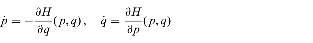
which can be written in the following matrix form:
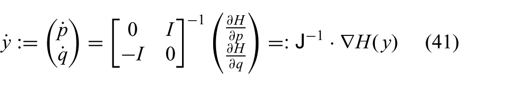
where
The Hamiltonian system (41) possesses three fundamental properties, namely, energy conservation (or passivity), momentum conservation, and symplecticity. Since the first two are familiar, here we explain only the symplecticity. A linear mapping

for
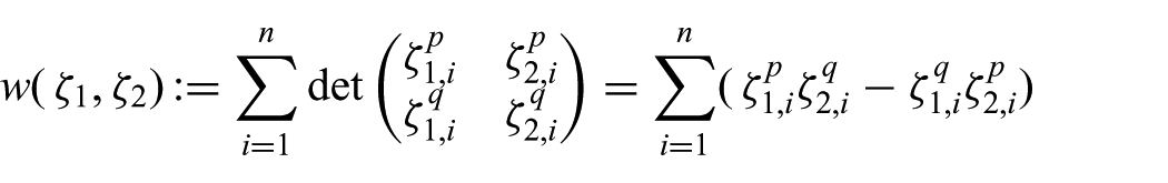
which is the sum of the oriented areas. In other words, symplecticity implies area preservation through the map A. For the Hamiltonian system (41), the symplecticity condition is given by
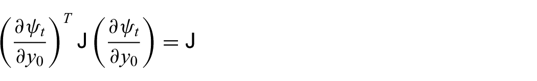
Symplectic integrators are those that preserve this symplecticity property of the continuous-time Hamiltonian system (41). The following symplectic Euler integration and implicit midpoint integration are those symplectic integrators:
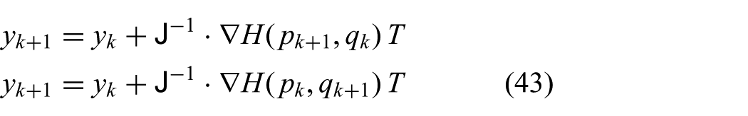

with the first two being SEI and the last being IMI, where
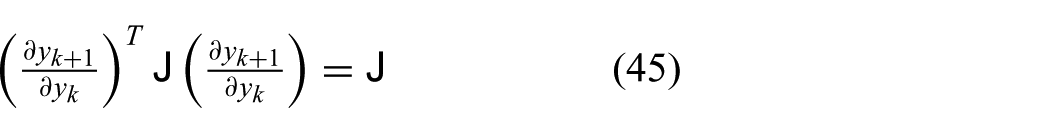
Now, let us see if the PMI (39)–(40) is also symplectic. For this, from (39) and (40), we can obtain the following equation:
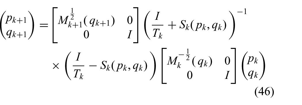
where
To derive (45) from (46) turns out to be too complicated to analytically perform. Note however that we have
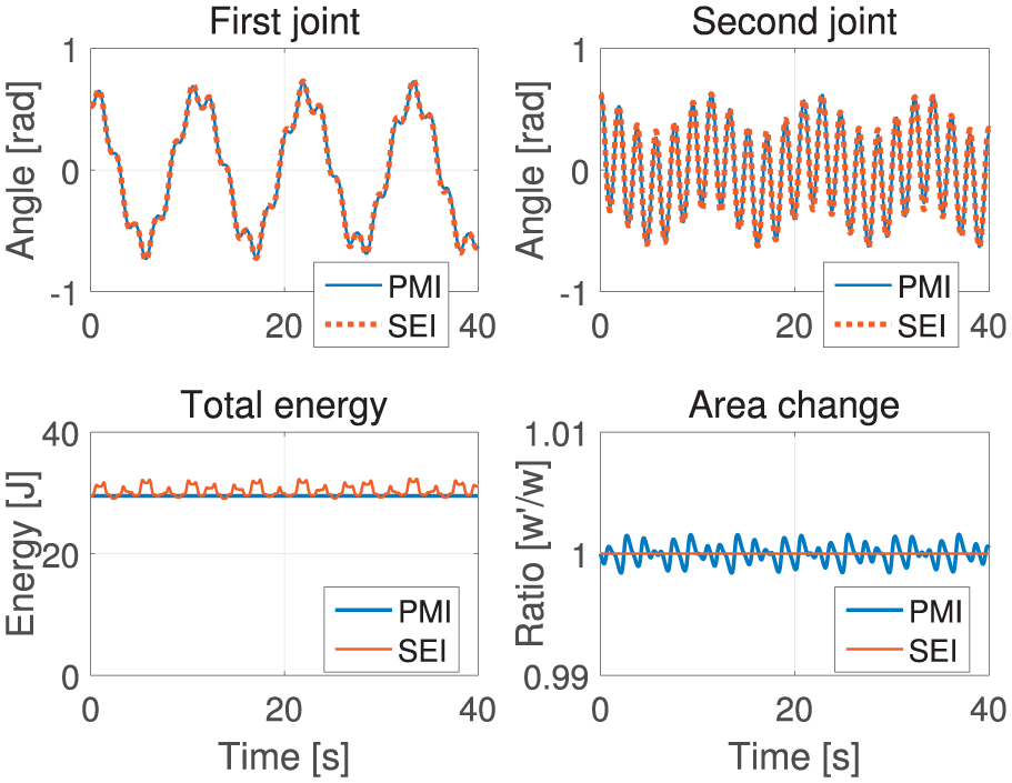
Simulation of two-serial-link robot arm with linear joint springs with SEI and PMI: the SEI is symplectic, but not exactly energy-preserving, whereas the PMI is energy-preserving, but not exactly symplectic.
Even so, we believe the PMI has advantages for haptic rendering and interactive simulation as compared to the symplectic integrators, particularly due to the following two powerful properties: (1) non-iterativeness and (2) passivity. Note first from (43) and (44) that the symplectic integrators should in general solve the nonlinear map (i.e.
On the other hand, note from (26) or (39) and (40) that the PMI is non-iterative with no requirement to solve such a nonlinear map. This non-iterativeness of the PMI is attained due to the coordinate transformation (36) (for nonlinearity from inertia) and the potential action approximation (e.g. (24) for potential nonlinearity). Of course, with this approximate action of nonlinear potentials, the passivity will also in general be only approximate. This “leakage” of passivity can however be rather easily resolved by injecting (typically small) linear damping B, which can still be simulated quickly due to the non-iterativeness of the PMI and whose passivity is also still guaranteed due to the passivity of the PMI. This unconditionally stable/passive damping allows for the so-called “controllable damping” (e.g. increase (or respectively decrease) B for more stable (or respectively less stable) behavior while preserving simulation stability), which is not possible for the symplectic integrators, theoretically or practically (i.e. precision of nonlinear map-solving). The non-iterativeness and passivity, we believe, are more relevant than symplecticity and momentum-preserving to haptic rendering and interactive simulation, since stability and real-time interactivity are their most fundamental requirements and their simulated objects are also typically under the influence of frequent human or contact forces, which is different from objects in celestial mechanics or molecular simulation, where long-term isolated behavior simulation is more important.
4.3. PMI-LCP for multi-point Coulomb friction contact
Following the procedure in Section 3.3, here we utilize the point contact model with Coulomb friction. Here, we assume the multi-DOF Lagrange system (39) interacts with a static virtual rigid object. We choose this static object for simplicity: the derivation presented below can be easily applied to multiple moving rigid objects, which can then be rendered by using the PMI expression in maximal coordinates from Section 3. We also adopt the velocity-level complementary condition as in (27) and the
Then, the contact force
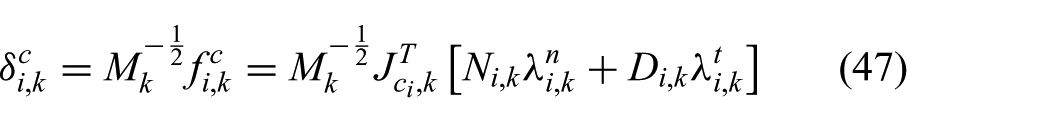
where

where
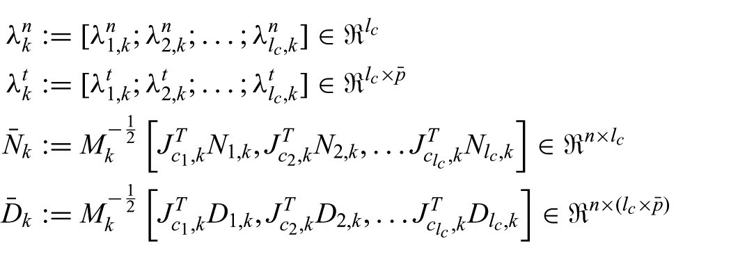
with which we can also rewrite the PMI expression of the Lagrange dynamics (39) similarly to (30), that is,

where
Given this
where
where

where
Finally, similarly to (34), we can construct the PMI-LCP formulation in generalized coordinates:
where
which can be solved by an interior point method or Lemke’s pivoting algorithm (Cottle et al., 2009).
5. Illustrative examples
So far, we have derived the PMI-based simulation framework, which, due to its enforcing passivity being effective in practice, can stably simulate a wide range of parameters (e.g. very light/stiff objects with no damping) regardless of (possibly varying/slow) integration steps
5.1. Peg-in-hole task
For the peg-in-hole task, we model the peg and the box with holes as rigid bodies, and the two multi-fingered virtual hands as articulated rigid bodies with joint constraints as shown in Figure 4, each composed of 10 articulated rigid bodies. To simulate these, we apply the PMI-based formulation in maximal coordinates from Section 3. We also utilize the wearable cutaneous haptic device (CHD) proposed in Kim et al. (2016), which can provide 3-DOF contact force feedback at the fingertip. This CHD is different from typical haptic devices (e.g. Omega 3, Geomagic Phantom), as it cannot generate kinesthetic force feedback. Consequently, we utilize unilateral virtual coupling to allow the user to command the position/orientation of the virtual hands/fingers, whereas the fingertip contact force is directly fed back to the CHD.
More precisely, the SE(3) springs, consisting of the E(3) linear spring in Section 2.2 and the SO(3) spring in Section 3.1, are used as uni-directional position/orientation-commanding virtual coupling (e.g. Kim and Lee, 2017; Lee, 2009). On the other hand, the contact force of each fingertip of the virtual hands during the manipulation (computed via the PMI-LCP in Section 3.3) is directly fed back to the cutaneous fingertip haptic device. For this, we use
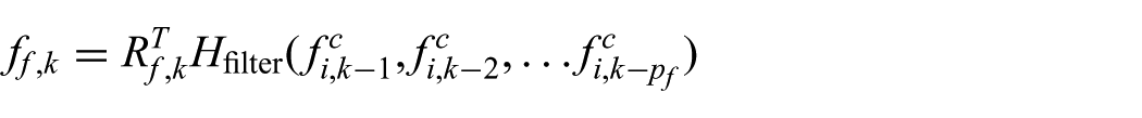
where
Snapshots of this peg-in-hole task are shown in Figure 10 with its fingertip forces also presented in Figure 11. We set the mass and inertia of the rigid bodies of the hand as
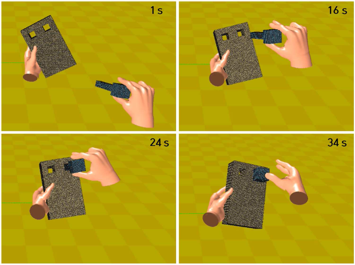
Snapshots of peg-in-hole task with two multi-fingered hands, each modeled as an articulated rigid body as shown in Figure 4 and making contact with the objects via friction contact simulated by the PMI-LCP in Section 3.3.
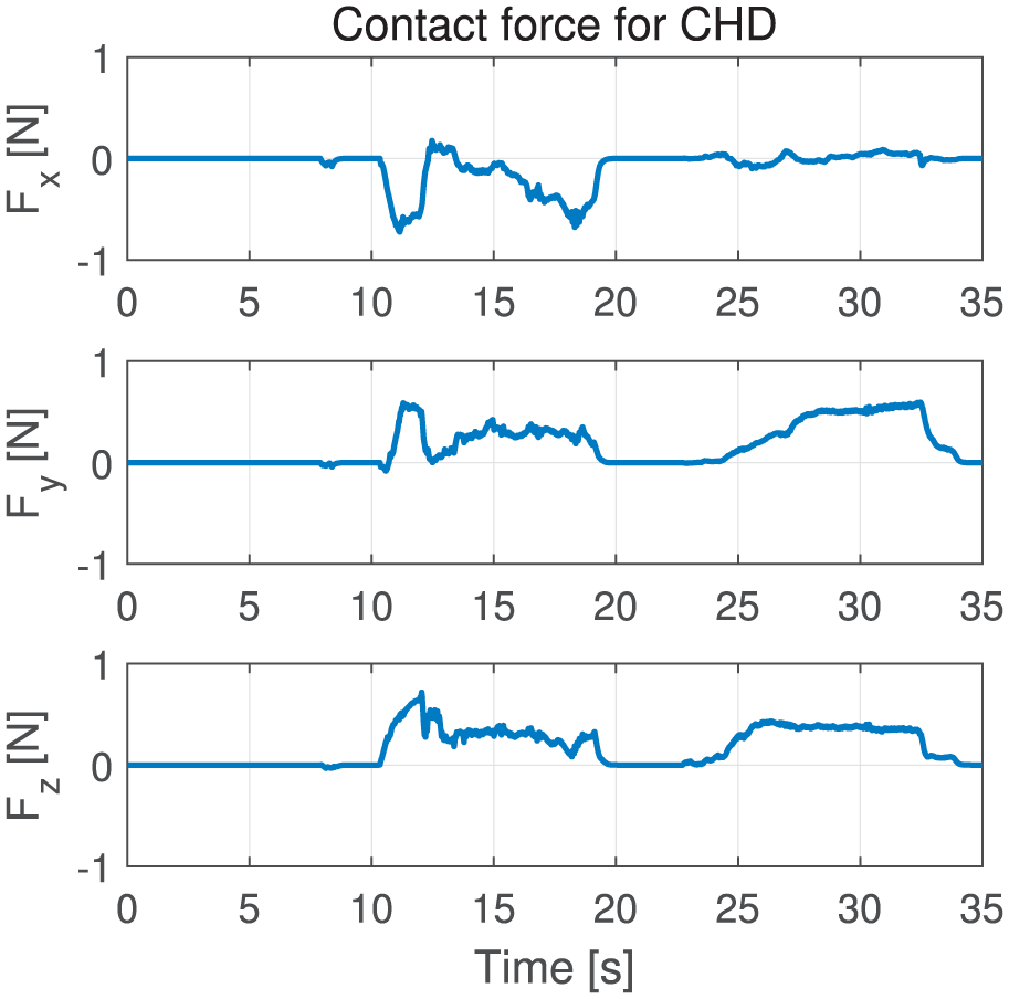
Fingertip contact force during the peg-in-hole task of Figure 10 expressed in the fingertip coordinate frame (with the z-axis being the contact normal direction).
5.2. Haptic interaction with flexible beam
We model the flexible beam to be an aluminum beam with the dimensions
where
Snapshots and profiles of kinetic, potential and total energies of undamped vibrations of this flexible beam simulated by our PMI-based framework with x=0 are shown in Figure 12 and Figure 13, respectively, where the integration interval is 1 kHz. There, we can see that the total energy is conserved throughout this fairly fast undamped vibration, clearly showing the ability of our PMI-based framework to simulate lossless, marginally stable or energy-conserving behavior. This undamped harmonic oscillation cannot be stably simulated by the SEI. It can however be done by the IEI, for which we must adopt some linearization as introduced in Duriez et al. (2006) and Courtecuisse et al. (2015) to render the IEI interactively fast. The results with this IEI simulation are shown in Figure 14, where it is clear that the IEI exhibits strictly stable oscillation with the total energy quickly decaying to zero. This lack of ability of the IEI to simulate lossless behavior is in fact due to its dissipativity (see Section 2.3), meaning that its advantage over our PMI framework is unclear, as the implementation complexities of PMI and IEI are at least comparable.
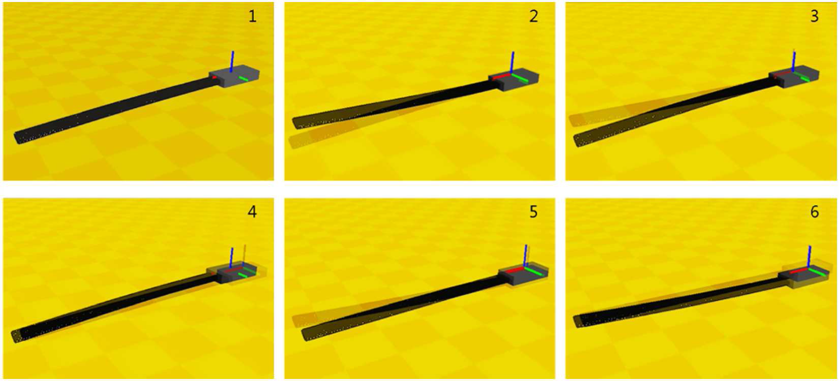
Snapshots of PMI-based simulation of undamped flexible beam harmonic oscillation.
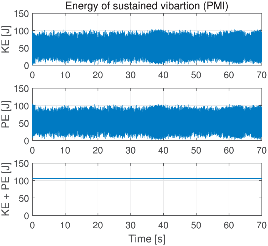
Profiles of kinetic (KE), potential (PE), and total (KE+PE) energies of the PMI-based simulation of undamped flexible beam vibration in Figure 12: note the exact conservation of total energy during fast oscillations.
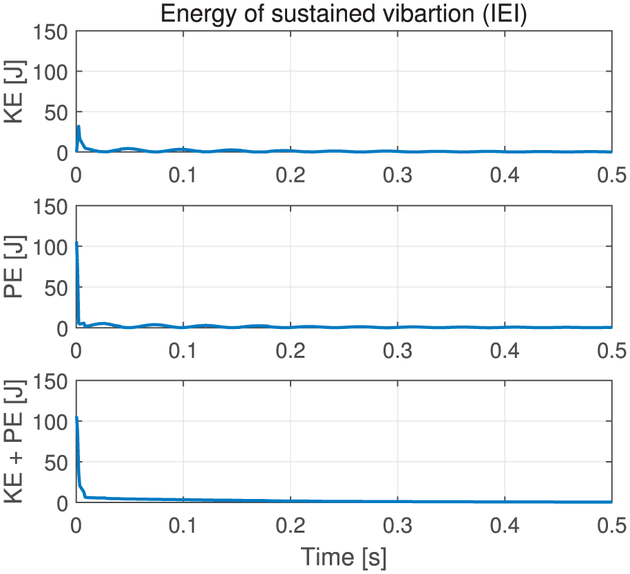
Profiles of kinetic (KE), potential (PE), and total (KE+PE) energies of the IEI-based simulation of undamped flexible beam vibration in Figure 12 with linearized inertia matrix: note the total energy quickly decays due to dissipativity of the IEI, although the same initial conditions as in Figure 13 are used.
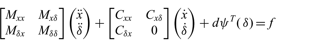
For the haptic interaction, we connect the flexible beam to a square rigid box via a spring, which is in turn connected to an Omega 3 haptic device via virtual coupling (Lee et al., 2012); see Figure 15. The dynamics of the total system can then be written as
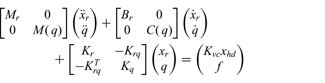
where
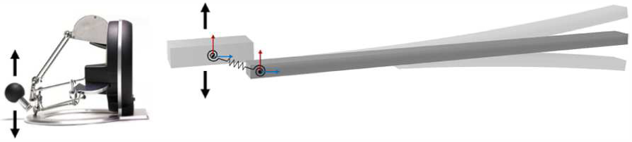
Flexible beam (in generalized coordinates) is connected to rigid body (in maximal coordinates) via spring, which is in turn connected to haptic device via virtual coupling.
We then implement the virtual coupling according to Lee et al. (2012), which was derived to be applicable to PMI while also enforcing (hybrid-time) two-port passivity of the virtual coupling. For instance, with no virtual coupling damping, the force feedback to the haptic device is given by

which, even if it contains
A profile of haptic feedback along the vertical z -direction of the haptic device during the interaction with the flexible beam is shown in Figure 16, where the user haptically interacts with the (lossless/marginally stable) flexible beam through the rigid box and virtual coupling, partly formulated in generalized coordinates and partly in maximal coordinates.
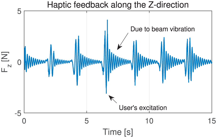
Haptic feedback from the flexible beam to the haptic device through virtual coupling connected to the rigid box.
5.3. UATD hand grasping
The last example is the adaptive power-grip of a virtual rigid ball by a multi-fingered UATD hand as shown in Figure 17. For the hand, we emulate the configuration of the iRobot-Harvard-Yale hand (Odhner et al., 2014). We model each finger to be constructed according to the design of Ozawa et al. (2014). For this case, it is then much more convenient to model each finger in generalized coordinates (i.e. joint angles), but model the hand’s palm and the virtual ball in maximal coordinates in SE(3).
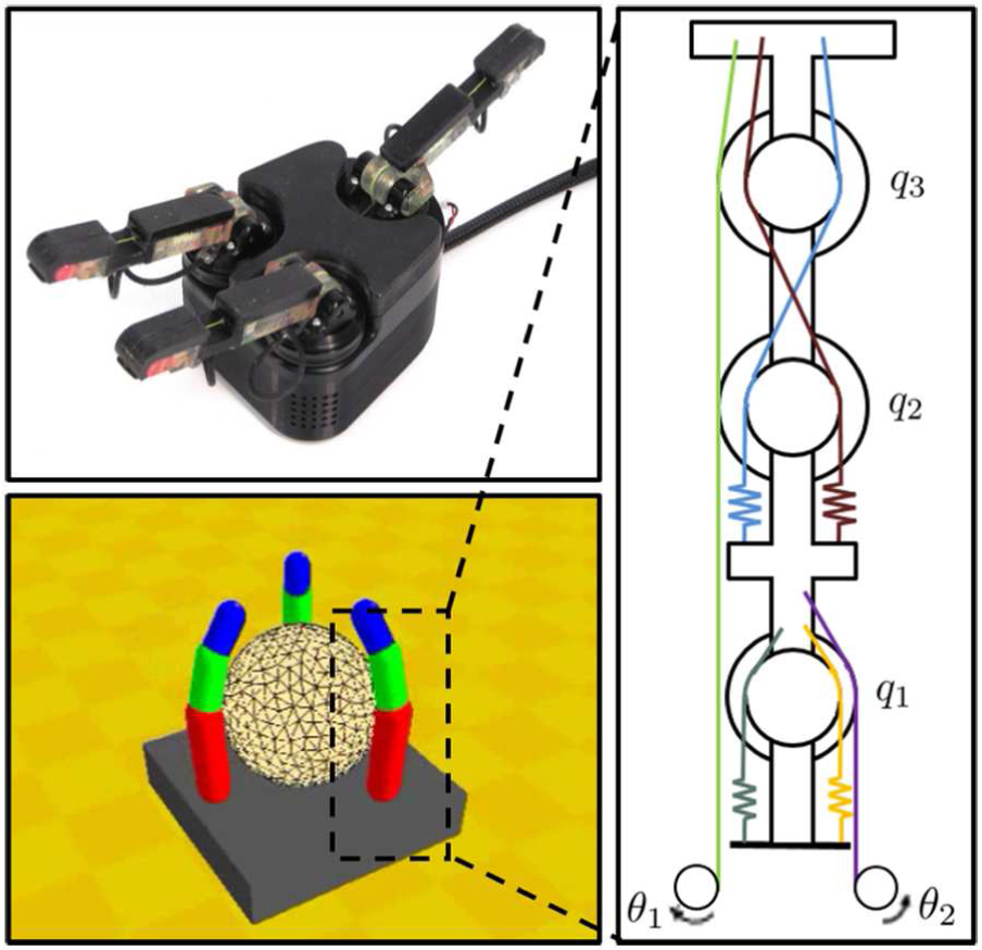
The iRobot-Harvard-Yale hand (top left), the three-fingered virtual UATD hand used in the simulation (bottom left), and the tendon routing of each finger (right).
Each finger is of three DOF, but with only 2-DOF actuation via active tendons. See Figure 17 for their tendon routing (adopted from Ozawa et al., 2014). There are two active tendons (green and orange lines) and four passive tendons (other lines). The configuration of the UATD hand is then given by the nine joint angles
where

similar to (4), where

where
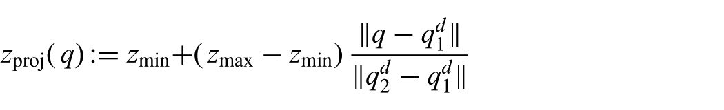
To control the adaptive under-actuated power-grip of this UATD hand, we use the Omega 3 haptic device as in Figure 15. Here, we only use one DOF of the haptic device (i.e. z -direction vertical motion) to command the power grip. For this, we first map
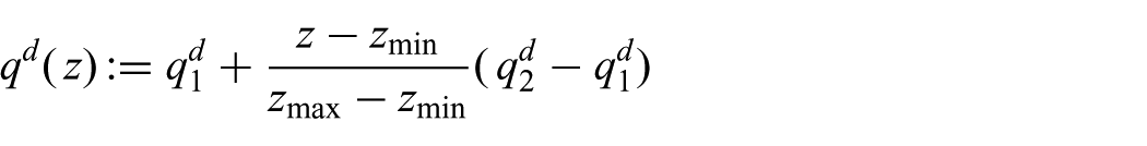
where

Of course, the UATD hand in general cannot exactly follow this

where
Snapshots of this adaptive power-grip of the multi-fingered UATD hand are shown in Figure 18, and the contact force feedback is shown in Figure 19. For this, we use
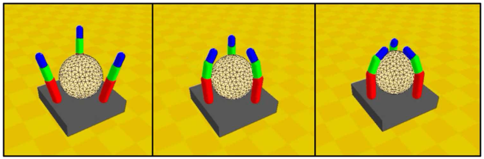
Snapshots of adaptive power-grasping of virtual rigid ball by the three-fingered UATD hand, with each finger having tendon-routing as depicted in Figure 17, with the three fingers simultaneously controlled by one DOF of the haptic device.
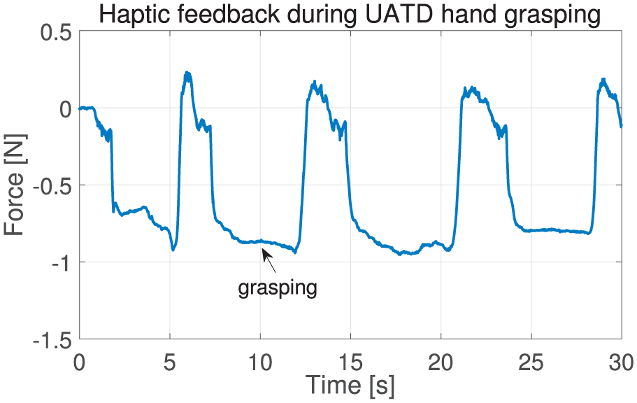
Haptic feedback of the 1-DOF (i.e. z-directional) contact force of the adaptive power-grasping of the UATD hand in Figure 18.
6. Summary and future research
In this paper, we develop a novel framework for haptic rendering and interactive simulation which is based on the PMI, which is derived by directly enforcing the passivity property in the discrete-time domain. We formulate this PMI-based framework for mechanical systems, both in maximal coordinates and generalized coordinates; we also devise a PMI-LCP formulation to fully incorporate multi-point Coulomb friction contact modeling into these two coordinate settings. Thanks to its passivity property, our PMI-based framework allows us:
to tune the virtual objects freely by exploring a wide range of parameters in a modular manner;
to stably simulate very light/stiff objects (e.g. for transparency) even with variable/slow integration steps (e.g. due to intermittent multi-point contact); and
to emulate such marginally stable, lossless or energy-conserving behavior as the harmonic oscillation of flexible objects or elastic contact between rigid objects.
Furthermore, our PMI-based framework provides implementation flexibility and convenience, by allowing for both maximal and generalized coordinates, and also their combination, which are imperative when simulating some types of mechanical systems (e.g. a multi-fingered UATD hand). These advantages are experimentally demonstrated in this paper by using three illustrative examples: haptic operation of a peg-in-hole task; haptic interaction with a flexible beam; and adaptive power-grasping by a multi-fingered UATD hand.
Some possible future research directions include the following: (1) Extension of the PMI-based framework to large-scale deformable objects, including cutting-and-joining and fluidic simulation; (2) Combining the constraint-stabilizing potential and PMI-LCP formulation while respecting non-iterativeness and passivity of the PMI; (3) Geometric properties of the coordinate transformation (36) and its application to other problems; (4) Application of the PMI-based rendering for multi-user virtual reality and haptic interaction over the Internet; (5) Development of an open-source simulation platform based on our PMI-based simulation framework.
Footnotes
A. Appendix: Index to Multimedia Extension
Archives of IJRR multimedia extensions published prior to 2014 can be found at http://www.ijrr.org, after 2014 all videos are available on the IJRR YouTube channel at http://www.youtube.com/user/ijrrmultimedia.
INRoL_IJRR17_rev2.mp4
Acknowledgements
The authors would like to thank Hyunsoo Yang, ChangSu Ha and Juhyeok Kim for their help in preparing the illustrative examples in Section 5.
*
This is in contrast to quasi-static systems, for which time integration is typically not necessary; see e.g. Barbič and James, 2008; Bender et al., 2013; Ortega et al., 2007)
Funding
The author(s) disclosed receipt of the following financial support for the research, authorship, and/or publication of this article: Research supported by the Global Frontier R&D Program on Human-Centered Interaction for Coexistence (NRF-2013M3A6A3079227), by the Engineering Research Center Program for Soft Robotics (2016R1A5A1938472), and by the Convergence Technology Development Program for Bionic Arm (2015M3C1B2052817) of the National Research Foundation funded by the Ministry of Science, ICT & Future Planning, Korea.