
Abstract
High hardness ceramics are potent in their use for armour applications globally, but intrinsically brittle. This can result in fragmentation damage, as well as low multi hit capacity. In this work, alternative 250 mm diameter Ti-6Al-4V discs were produced using field-assisted sintering technology (FAST) with and without stepped functional grading using low wt.% TiB
Introduction
Threats from the use of small calibre armour piercing projectiles pose a great danger to both lightly armoured vehicles and personnel in combat zones globally. 1 Between this and the ubiquitous use of armour piercing projectiles around the world, a common threat to the military arises, requiring material solutions and pushing the development of new light armour materials to a position of higher demand. These new materials must have high hardness to fracture and erode projectiles, and fracture toughness, as well as elastic modulus to withstand multiple impacts, providing the highly desirable multi-hit capacity. This means that the material must be able to withstand multiple impacts without too great of a loss of these vital properties,2,3 reducing their effectiveness for subsequent impacts.
The candidates in this category include several ceramic systems, including B4C, SiC, Al2O3 and TiB2. These materials remain high on the list for light armour applications due to their low density, reliability, superior hardness and energy absorption capacity. 4 However, despite their deformation induced hardening increasing their resistance to the initial high impact velocity shot, they commonly shatter on impact. 3 This shattering can in fact further aid in increasing the impact resistance of the material by eroding and abrading the projectile, though it does challenge the multi-hit capability of this class of material. TiB2 as a ceramic also offers these required properties as an armour material, however it is challenging to create large plates with full consolidation of this material, requiring lengthy sintering times and temperatures in the range of 1500–1900°C under pressures of 40–70 MPa. 5 With lower compaction pressure, temperatures in excess of 2000°C are required to achieve similar densities, pushing the limits of sintering un many currently available machines.
One potential solution to both challenges, which has displayed lower, though still significant, peak protective capabilities than monolithic alloys 6 over the years, has been the introduction of metal matrix composites (MMCs). These contain both ceramics and metals, in the form of a composite material, with ceramic fibres or particles dispersed throughout a metallic matrix. Many of these such systems have been studied and one of the most promising is TiB in a titanium matrix.7,8 Titanium has been chosen by many for this system as the metal partner as it does provide significant toughness to the system whilst, most importantly, having a similar density and coefficient of thermal expansion to TiB/TiB2, and is therefore, thermomechanically compatible with minimal separation on cooling with no internal cracking. Whilst consolidating higher concentrations of TiB2 within the matrix would require these extreme processing conditions, lower weight percentages may be fully consolidated under temperatures that do not cause melting in the combined metal matrix. They may, however, still adversely affect the mechanical properties from microstructural effects and interfacial reactions. This is especially true for these titanium alloys which experience large prior β grain growth above the allotropic α (hcp) to β (bcc) transformation temperature of approximately 1000 °C, depending on the alloying elements. It may, however, be noted that this explosive grain growth can be avoided, as shown by Gupta et al. 4 in their sintering of this system as a functionally graded material (FGM) at 1500–1600 °C.
A FGM may be visualised as a stack of these metal matrix composite layers with varying concentrations of the ceramic particulate. The differing mechanical properties of each layer may be decided upon in advance to create a bulk performance suited to the needs of the task. In this case, the high hardness of the ceramic elements may provide impact protection on the surface attack face, while the relative ductility of the titanium alloy matrix allows for the absorption of the incoming energy and material on the rear face.
In this work, a functionally graded plate of 250 mm diameter has been produced using field-assisted sintering technology (FAST) to demonstrate the technique's capability to generate unique microstructural solutions to tackle complex, real world challenges at scale. This technique is a low voltage, DC-activated sintering technique using uniaxial pressure together with resistive heating, allowing it to consolidate a wide variety of materials. In addition, FAST performs this consolidation many times faster than other alternative techniques such as hot isostatic pressing (HIP) and is capable of high heating rates up to several hundred °C in some machines. 9 Another benefit of FAST is the ability to combine similar and dissimilar materials in a single step, which has been utilised here to layer specific depths of Ti-6Al-4V with varying TiB2 concentrations to create these MMC FGMs. It has even been shown to assist in reducing the generation of large residual stresses and pores in the material, therefore improving the ballistic properties. 10
These types of components have been created previously11,12 on smaller scales, and expanded in this work primarily through three areas. Firstly, the size of the samples at 250 mm diameter, as well as the use of previously cold milled powder, combining the ceramic and metal particles on a much more refined scale, allows for a homogeneous structure to be formed in a single sintering step. In addition, as mentioned, only low weight percentage ceramic inclusions are used, below 10 wt.%, with the intent of reducing weight whilst promoting the growth of TiB needles through the TiB2 + Ti reaction in situ increasing fracture resistance 13 and allowing full consolidation in a single step.
The generation of these needles has been previously demonstrated for this material composite, 14 using an annealing process 15 over a period of 5–50 h, as well as through in situ spark plasma sintering (SPS). 16 They possess no preferential orientation, noted by Feng et al., 12 from elemental generation, and a hardness multiple times that of the underlying titanium alloy substrate. As such, it is expected that their presence will provide several additional barriers and hard/soft interfaces for the impact shock wave and cracks to encounter, increasing the ballistic fracture toughness further compared to monolithic ceramics, whilst simultaneously providing higher hardness than the pure metallic system. Mechanistically, these needle shaped TiB grains provide this increase through the crack deflection, pull-out and the micro-fracture of the TiB discussed in more detail by Markovsky et al. 17 Separately, Radhakrishna et al. 18 postulated that the presence of TiB without the needle geometry would in fact weaken the strength and fracture resistance, making this system very thermally and process sensitive. These TiB2/Ti MMCs have previously been ballistically tested in other works with much higher percentages of ceramic inclusions up to 95 wt.%, 19 or as a bilayer design, 4 with equally large concentrations of TiB2 at 80–90 wt.%. However, as mentioned, the scales involved in this work have not commonly been seen, and may come with associated issues regarding thermal homogeneity, vital in a system seen to be potentially thermally sensitive. In addition to this, it is expected that the lower wt.% TiB2 inclusion is expected to increase needle production and consolidation, providing interesting insight into the material system and its potential for ballistic applications.
Methods
Sample creation
Initially the base titanium powder, Ti-6Al-4V and TiB2 ceramic were chosen due to their compatibility with each other and complimentary properties for the task. In addition, the TiB2 + Ti reaction, providing TiB needle growth is expected to be very beneficial if homogeneously dispersed throughout the microstructure. To achieve this, the powders were processed at Materion (Farnborough, UK), producing 3 wt.%, 6 wt.% and 9 wt.% TiB2 powders using a proprietary ball milling process using both the grade 5 ASTM standard titanium alloy powders and TiB2 with example BSE images of the resulting blend pictured in Figure 1.
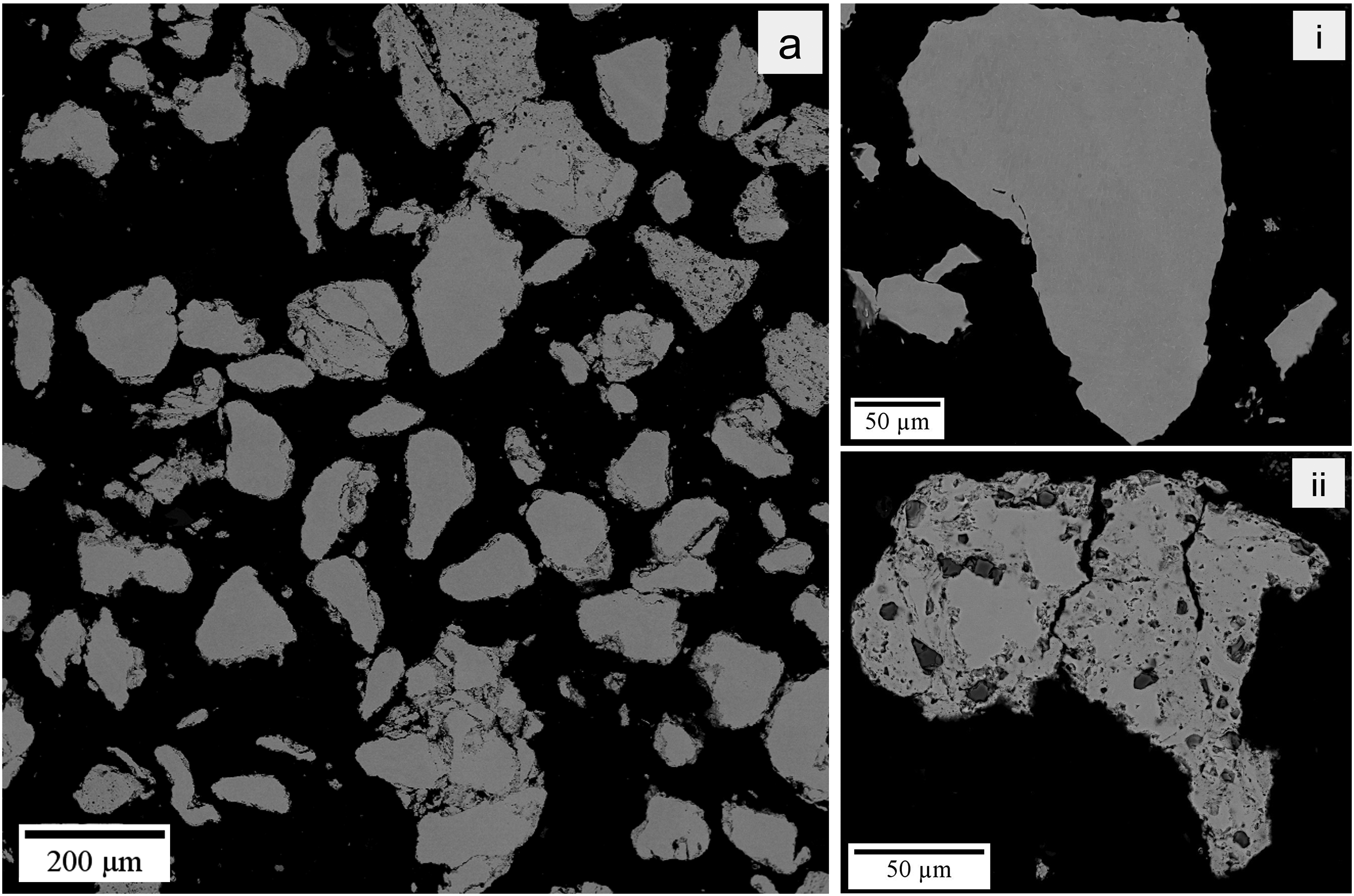
(a) A backscatter electron image of the 6 wt.% TiB2 milled powder with a higher magnification image (ii) and the unalloyed hydride dehydride (HDH) Ti-6Al-4V alloy powder (i).
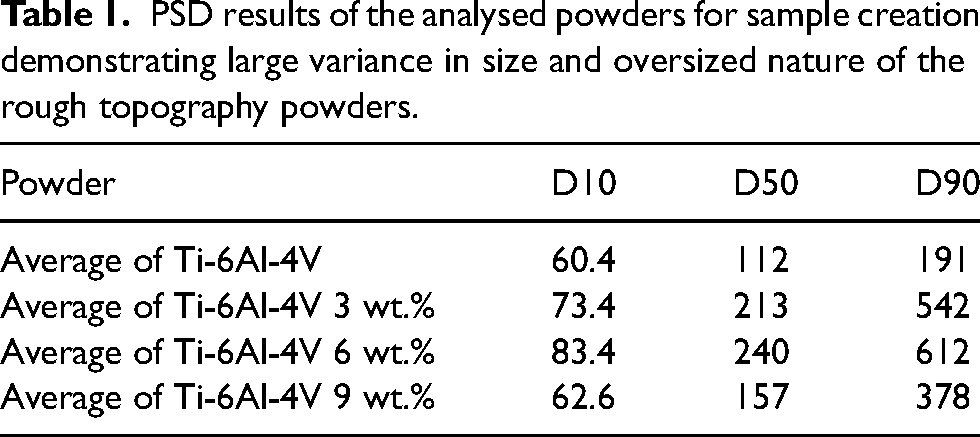
A portion of the particles have been very well seeded while others seem to be almost entirely untouched unexpectedly. It is believed that this is due to trapping of the TiB2 between the titanium alloy powders during cold welding in the milling process. This is especially visible in the larger particles like those pictured in Figure 1(a). The powder size distribution (PSD) analysis was performed using a Malvern Mastersizer 3000 laser diffraction particle size analyzer with a wet dispersion method. A total of three repetitions were conducted to confirm results and the D10–D90 scale was found and displayed in Table 1.
These powders were then laid up in functionally graded stages from 0 to 9 wt.% TiB2 inclusion with the aim to generate a high hardness high ductility interface depicted in Figure 2 before being sintered.
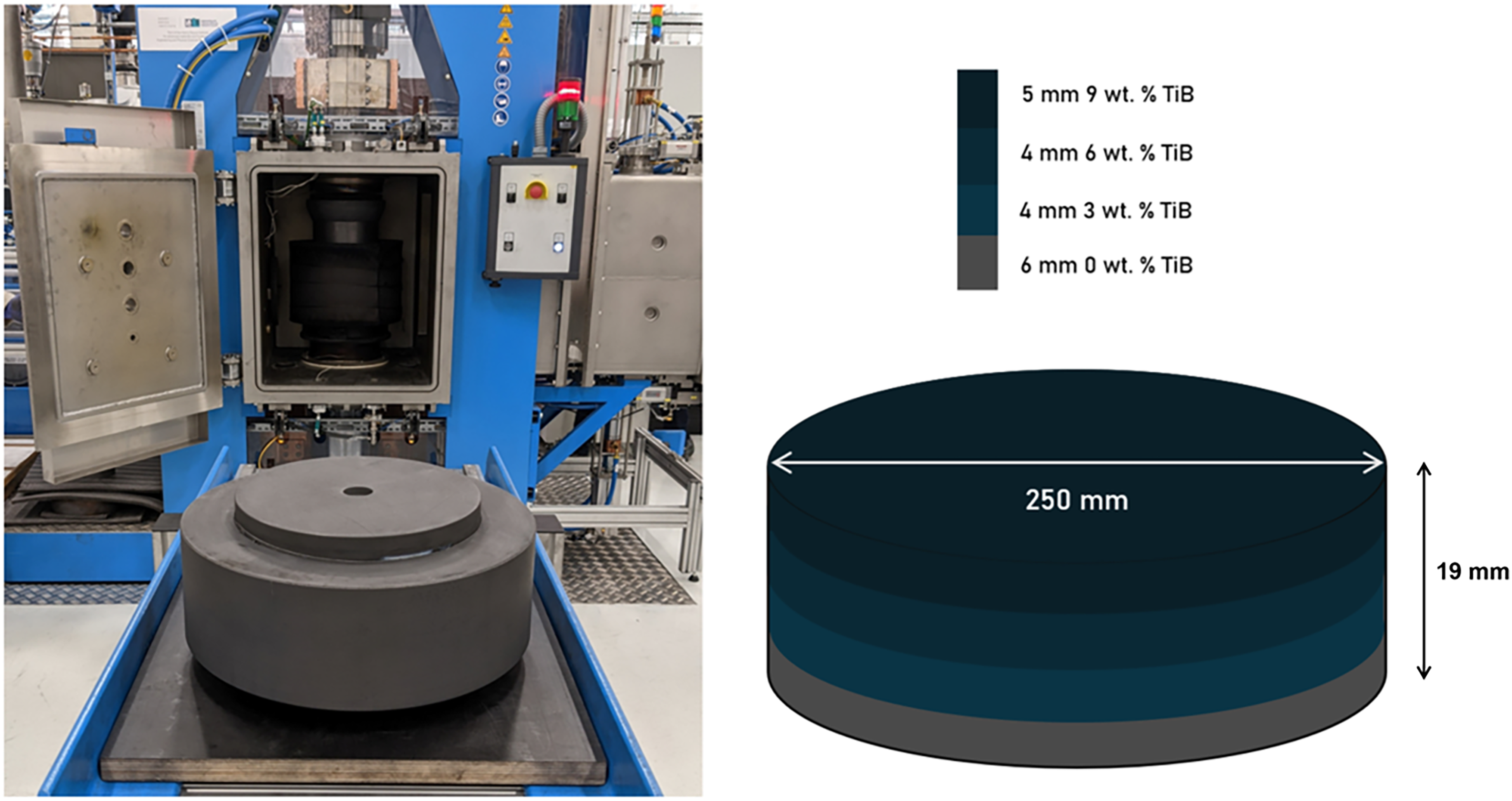
Photograph of the FAST machine and 250 mm diameter graphite mould used in sample creation (left) and internal designed layout of the target final height sample for ballistic testing (right).
Field-assisted sintering
The FAST machine firstly set a vacuum to 10−3 bar to prevent unnecessary oxidation, before the powder plates were pressed to 35 MPa and subsequently heated at a target rate of 100°C/min to a dwell temperature of 1350°C where they were held for 2 h before being allowed to cool in the machine through the water cooled electrodes. These sintering curves can more clearly be seen in Figure 3 along with the resulting ram displacement, representing the standard consolidation behaviour of the powder. This sintering was carried out in the FCT Systeme GmbH Spark Plasma Sintering Furnace type HP D 250 and monitored with a pyrometer measuring the temperature within the hollow ram. The FAST sintering machine used a pulsed current application of 15 ms on and 5 ms off DC current for easier comparison with previous work performed and for better consolidation. To assist with thermal homogenisation within the sample, graphite felt was included for insulation on the outside of the mould ring as well as on the top and bottom of the mould. The plate was then extracted and sandblasted to remove excess graphite from the surface. One Ti-6Al-4V plate of the same dimensions was prepared without any of the TiB2 layer additions as a control, and one more with the ceramic additions, photographed in Figure 6.
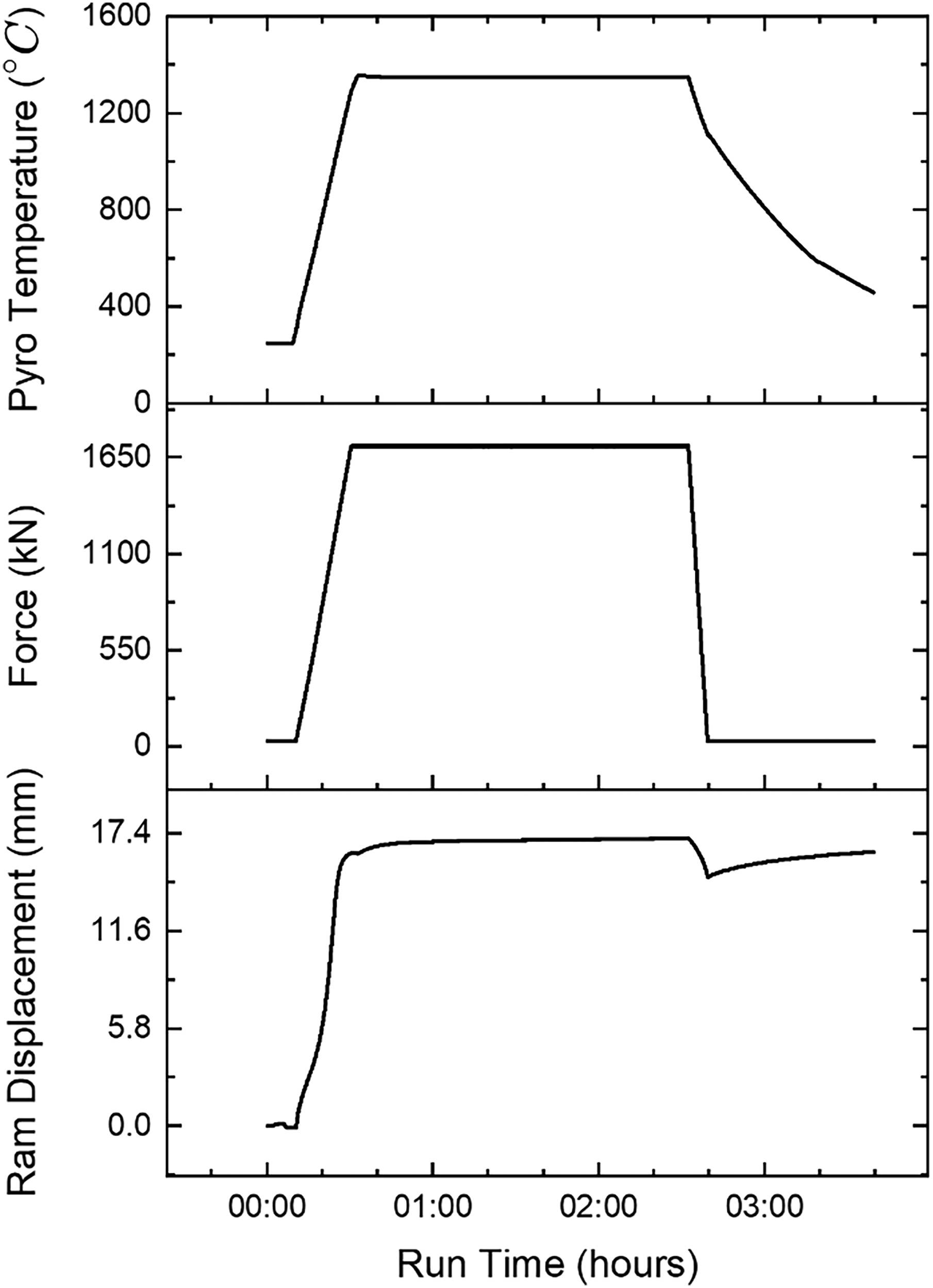
Graphical plots of the measured temperature, force, and RAM displacement from the FAST machine during TiB FGM plate processing, providing a visual representation of the consolidation behaviour during sintering.
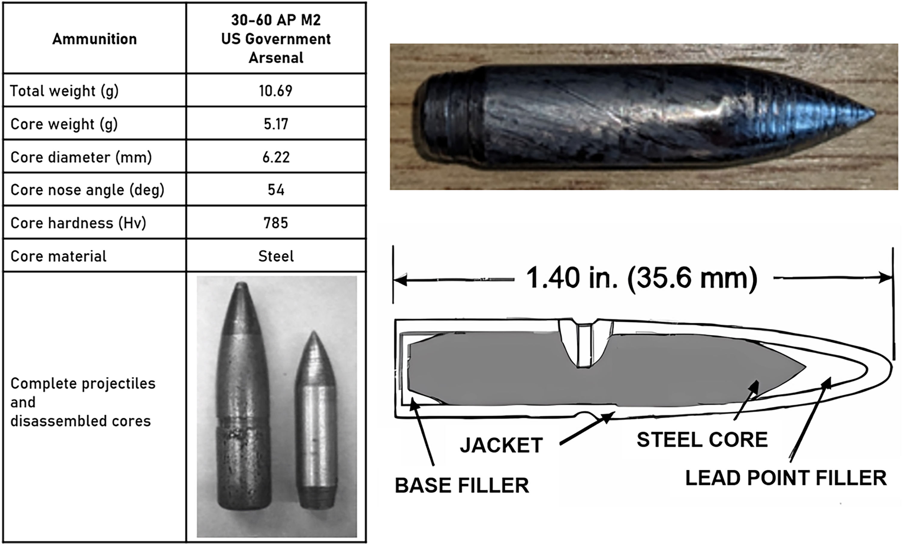
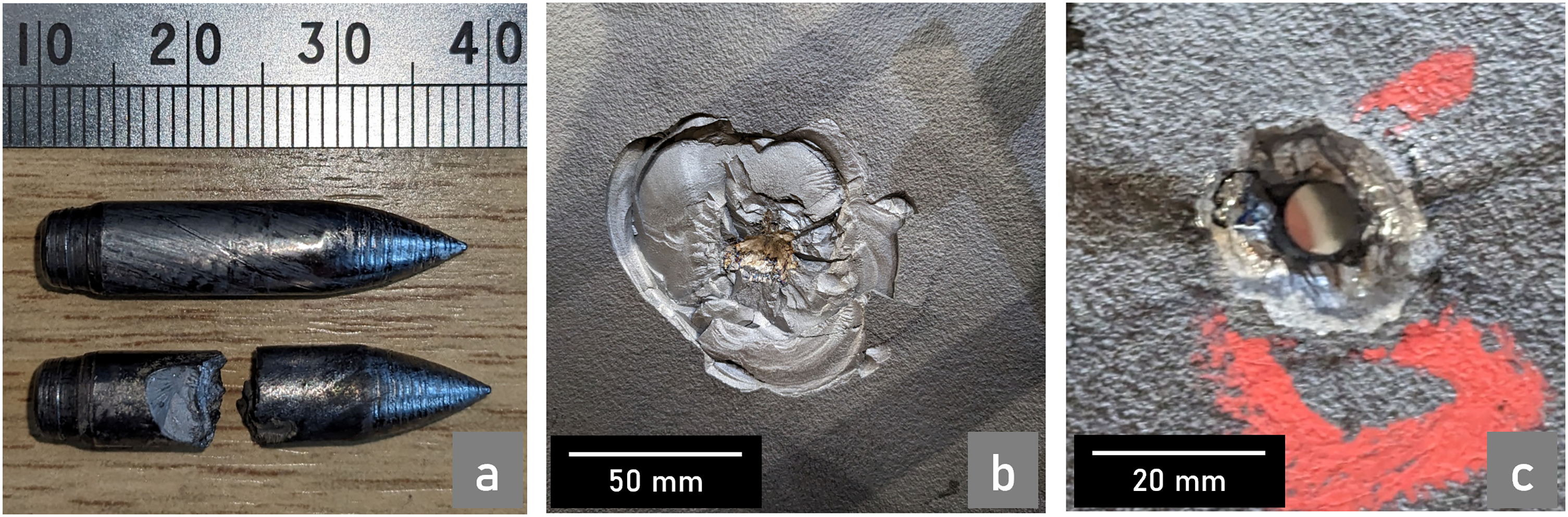
30-60 AP M2 hardened steel slug data sheet (left), photograph of the core and full schematic (right) images, adapted from RBSL documentation.
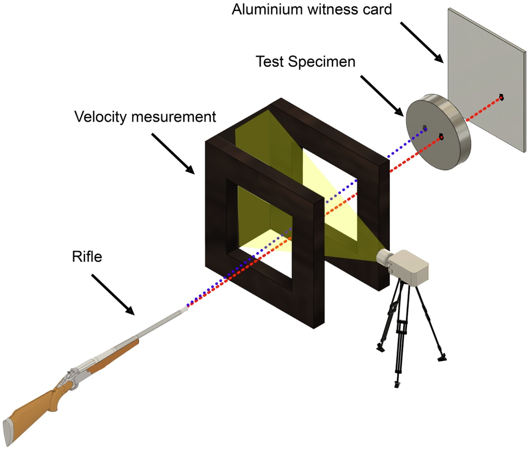
A visual schematic of the equipment used for the ballistic test, referenced with permission from Reference. 21
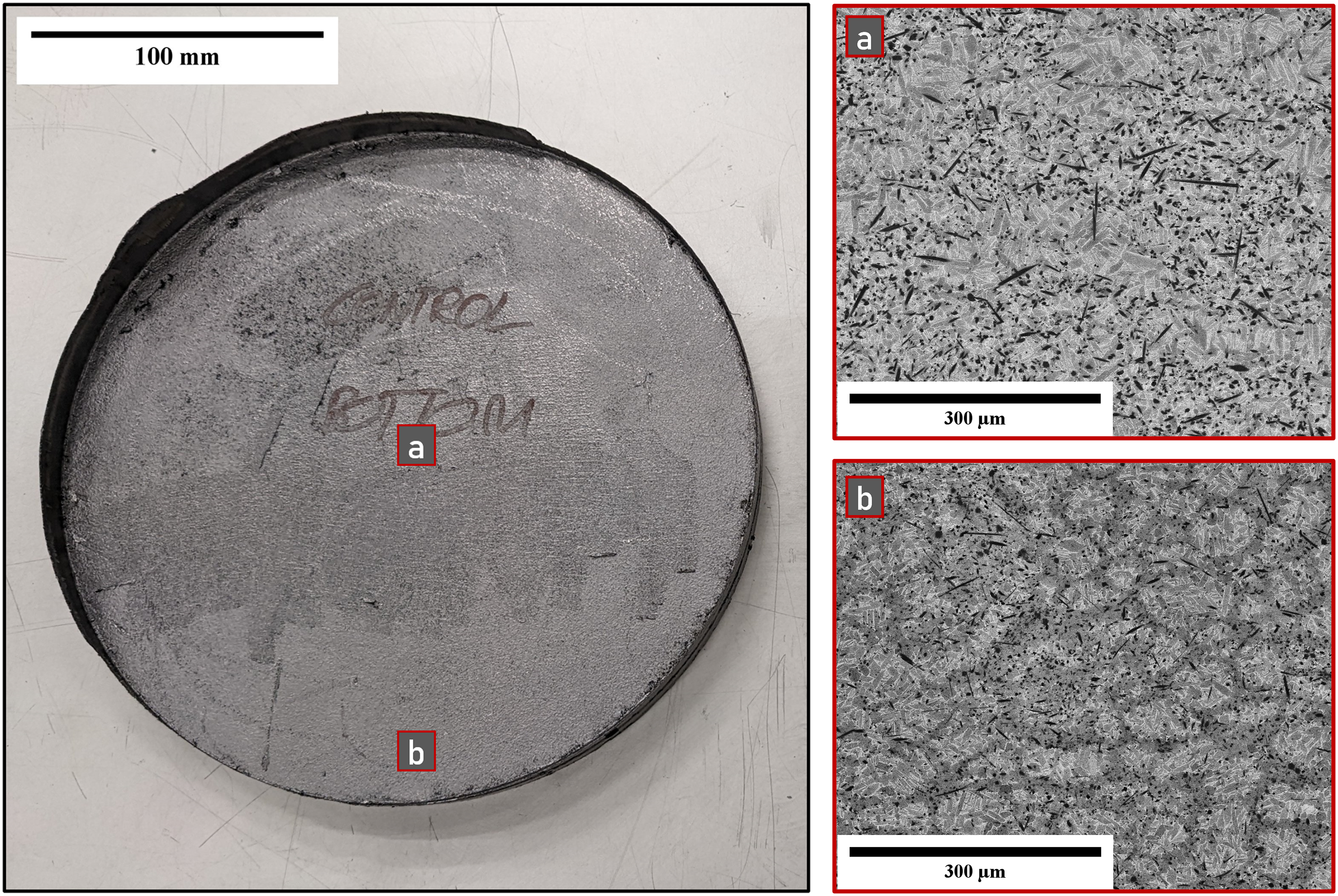
Photograph of the TiB2 reinforced plate produced post sinter as control (left) and locational BSE images (right) demonstrating needle growth and consolidation. For the plate, the faces were labelled to ensure that the correct attack face was tested.
Ballistic testing
The ballistic testing was conducted at Radnor Range in collaboration with RBSL and Dstl. During testing the plates created using FAST with diameter 250 mm and thickness 19 mm were further sandblasted to remove any remnant graphite foil from the process and, to aid clamping, ground down where edge creep occurred. An armour piercing 30-06 AP M2 hardened steel round was used as test projectile, as pictured and shown in schematic form in Figures 4 and 12. The bullet was aligned and fired at the target directly with 0 intended yaw and pitch, and the speed was measured as it passed through two infra-red light gates. This was required as the bullets were live fired with precisely measured powder weight for desired speed and could vary within an expected range when tested.
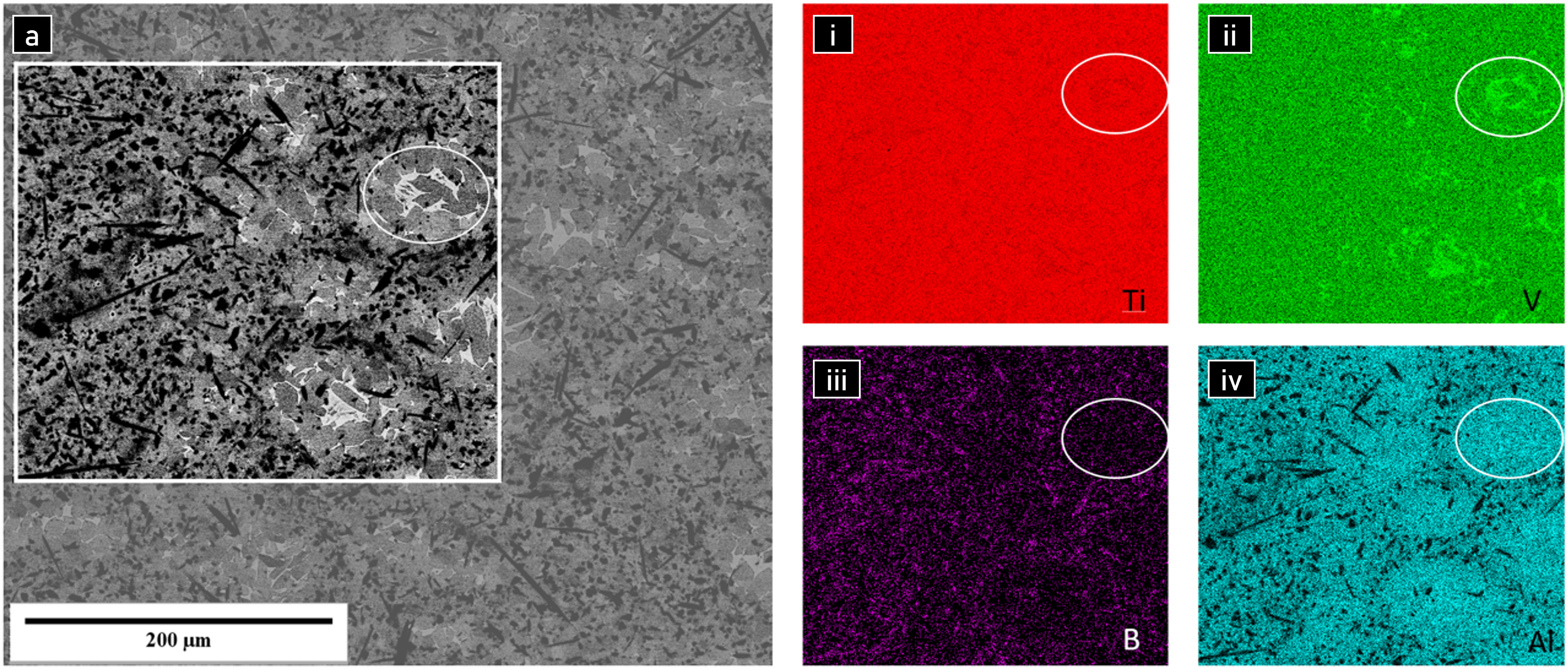
(A) BSE micrograph of Ti-6Al-4V + TiB region with associated X-ray energy dispersive spectroscopy (X-EDS) showing displacement of Ti (i), V (ii), B (iii) and Al (iv) from needle growth and distribution of these elements in the edge of the sample, displaying the heterogeneous distribution of needles in high variance regions.
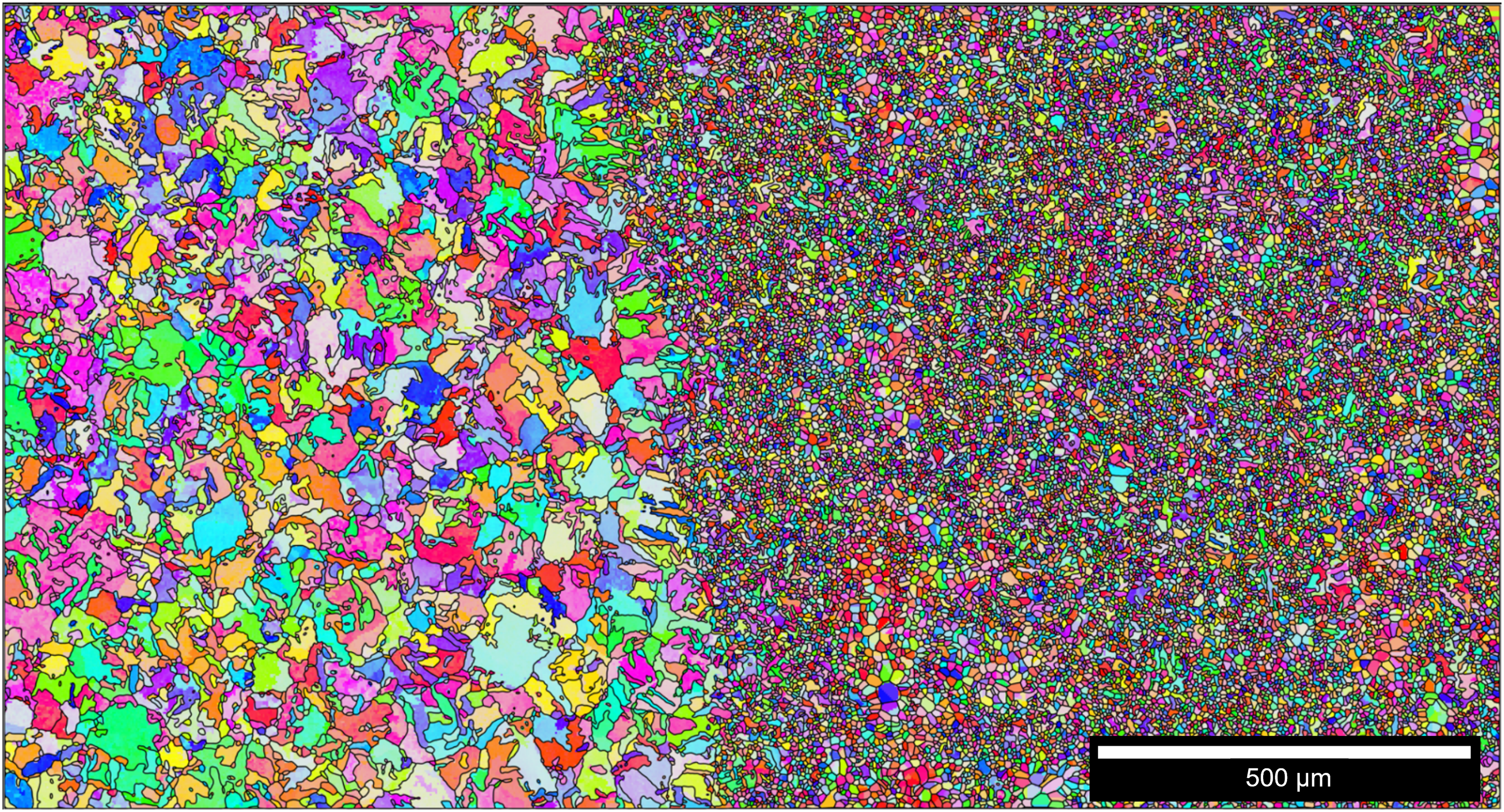
EBSD of the Ti-6Al-4V + 3 wt.% TiB2 interface demonstrating extreme grain pinning from the TiB2 and TiB ceramic particles on the growth of the titanium alloy prior β grains
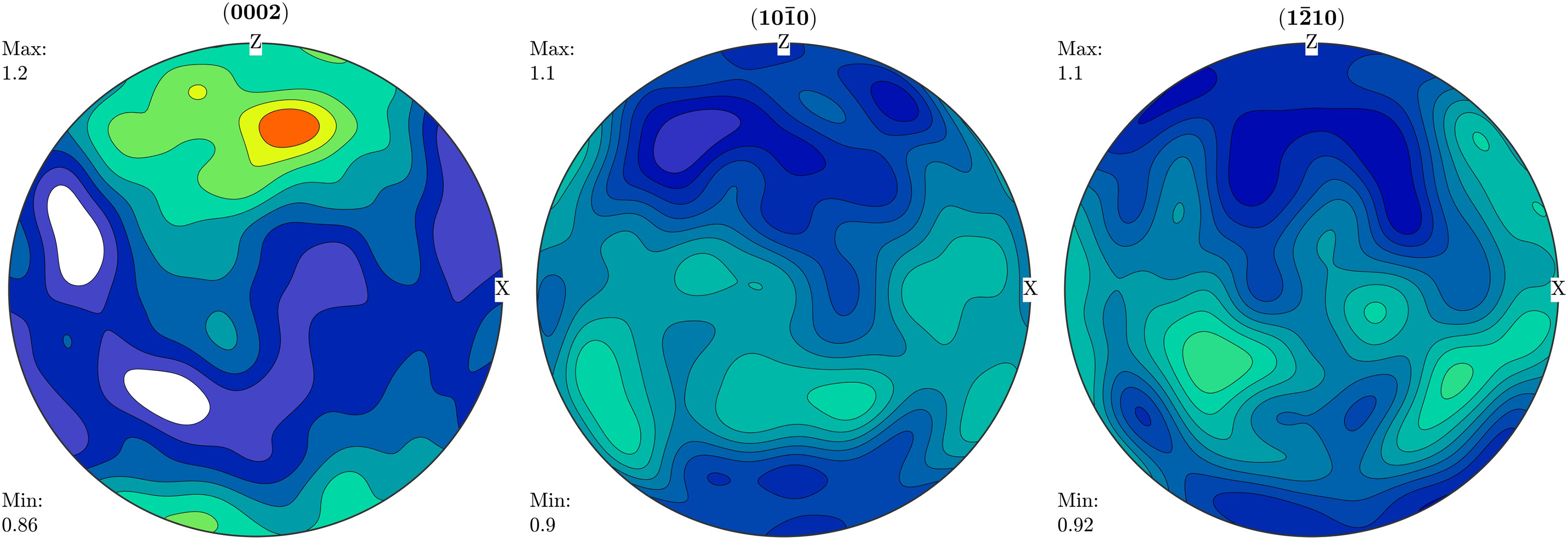
Pole figures showing the lack of strong crystallographic texture seen in Figure 8, consistent through both regions.
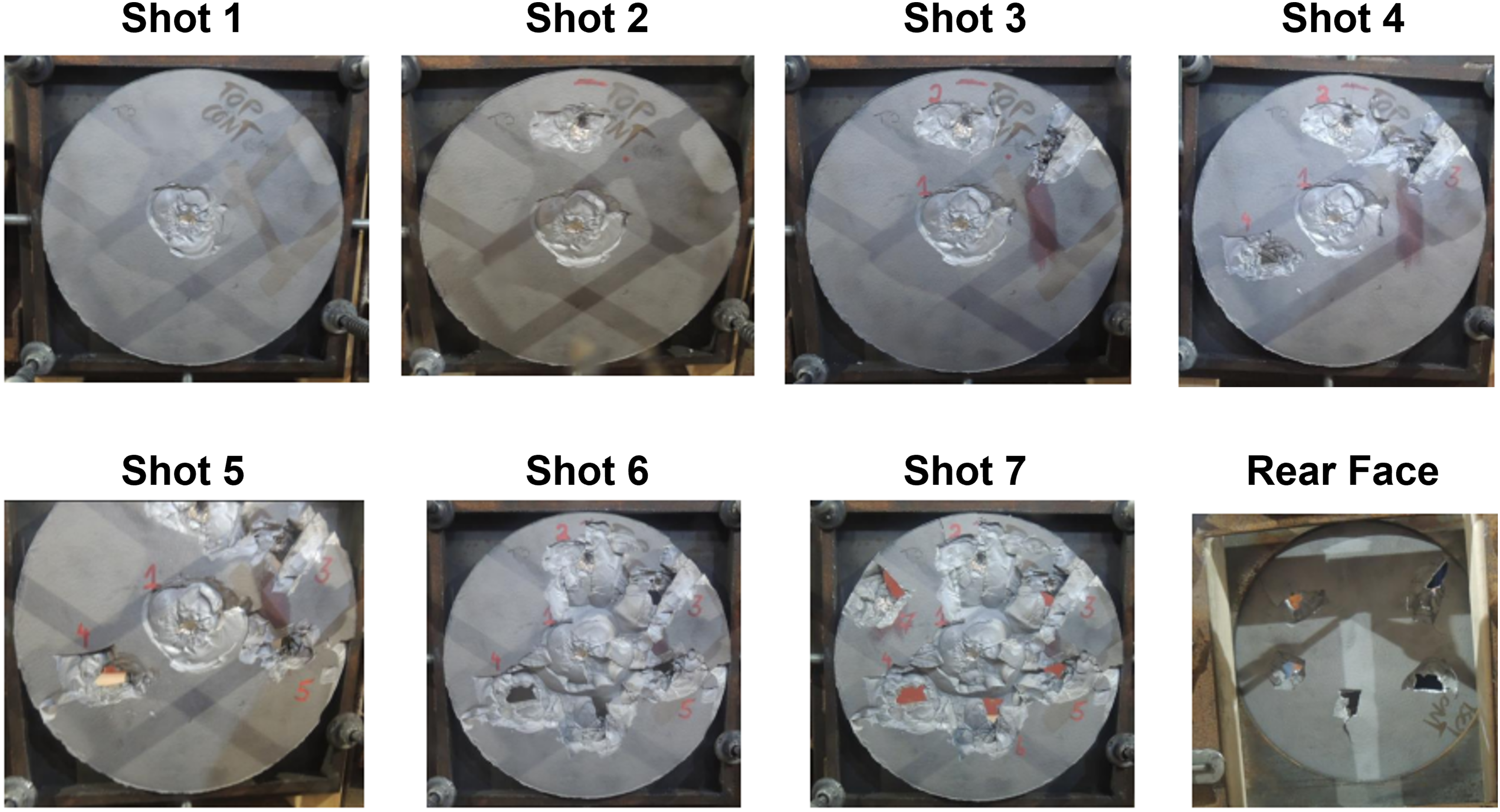
Photographs of the impact faces taken after each shot into the control TiB functionally graded plate, as well as the final shot rear face demonstrating the scabbing failure mechanisms.
(a) Photograph of the hardened steel slugs fired at the metallic target plate (top) and the ceramic plates (bottom). (b) Impact (pass) on ceramic attack face. (c) Impact (fail) on metallic face.
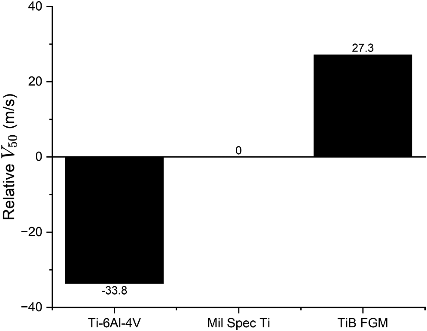
. Relative V50, results normalised to military specification (Mil Spec) titanium alloys for the same thickness and firing conditions, processed at 1350 °C.
An indicative V50 was determined using two passes and two failures at as narrow a range of velocities as possible with the material available. It is noted here that there is a limited data set from the available material and as such the calculated V50 values can be considered indicative for the MMC plates. A failure is determined by whether the aluminium alloy witness sheet, placed behind the plate during the test as depicted in Figure 5, had been perforated sufficiently to let light pass through. Three outcomes are possible for the test; complete penetration (CP), partial penetration (PP), no penetration (NP) with NP and PP counting as passes and CP as failure. Usually, with enough shots, a narrow range for this V50 value can be obtained and then further testing may improve the precision of this measurement. However, for these plates, the MMC/ceramic nature of the target minimises the number of potential shots per surface area. It must be noted however, that the repeatability of impact testing in a non-tile format is not guaranteed for dense ceramic targets 20 and this multi-impact tolerance is a positive for this system.
The plates were photographed each time a test firing occurred to document the impact and locations of impact on the attack face as well as how the plate held up to multi-hit testing. Once firing was completed, a rear face photograph was also taken to examine the scale and mechanisms of failure for the shots if the sample had maintained its form.
Microstructural analysis
Once the plates had been ballistically tested in the as FAST condition they were sectioned, mounted in conductive carbon filled PolyFast™ Bakelite and ground and polished using a Struers Tegramin-25. Grinding was performed for 2 min using P800, P1200 and P2500 SiC grit papers, followed by polishing with a nine part 0.06 µm colloidal silica and one part hydrogen peroxide suspension for 10 min. After having been prepared, the samples were analysed using light and electron microscopy. The initial optical micrographs were taken using the Olympus™BX51 microscope, to identify features of interest for more focused imaging on the Inspect F50 Secondary Electron Micrograph image with 20 kV accelerating voltage.
Microhardness testing
The hardness values were taken on a DuraScan™Micro/Macro Hardness Tester for the fully consolidated samples sectioned from areas unaffected by the surface impacts due to a lack of available material. These were further corroborated by additional samples created under the same temperatures and processing conditions recorded on smaller scale samples. For this testing, a low load was used of 1 kgf for a hold time of 15 s. A diagonal line pattern was used for testing the trend through the layers, confirmed with a grid pattern within the layers for statistical data.
Results and discussion
Initial microstructural analysis
X-EDS
X-EDS testing was performed to more quantitatively display the homogeneous/inhomogeneous boundaries seen in the micrographs and explain them on a more fundamental level. In the SEM image (left) in Figure 7(a) region of poor homogenisation at the edge of the TiB2 plate from Figure 6 is displayed. This was a region with a lower expected processing temperature from inherent thermal gradients and therefore higher expected variance in hardness. What can be seen in the element maps is that the regions richer in boron Figure 7(iii), slightly lacking in titanium (red) Figure 7(i), and much more significantly lacking in aluminium (blue) Figure 7(iv), are where the needles are present. The vanadium (green) Figure 7(ii) scan appears to have no variation in the presence of the needles but there are higher concentrations in TiB sparse regions. As expected with this alloy, most of the vanadium segregates to the β phase within the microstructure. From point scans it is also known that this difficulty observing needles may also be due to a poor background count for Vanadium, meaning the lower-level green values are to be taken as background, or near 0 content. What can be inferred from this is that in areas with less exposure to high temperatures during the sintering phase, the boron has had less ability to diffuse throughout the surrounding titanium alloy powders, seeming to trap them in islands of microstructure and providing brittle pathways for cracks to potentially propagate through. The TiB needles that do grow appear, visible most clearly in Figure 7(a)(iv) to primarily react more aggressively with the titanium on the boundaries of the TiB2 clusters when temperatures are reached, pushing the alloying elements out and increasing their concentrations in islands sufficient dwell and energy allows for the heavier atoms to diffuse. For some of these TiB2 concentrations, hardnesses up to 1300 HV were observed, which is approaching fully consolidated TiB2 hardness values in excess of 2200 HV. This is incredibly brittle relative to the Ti-6Al-4V particles with almost one-eighth of this value at 300 HV, resulting in the mechanisms and resulting poorer performance discussed previously.
Electron backscatter diffraction
Electron backscatter diffraction (EBSD) analysis was also performed to clarify the resulting grain structure and demonstrate the impact of the addition of the TiB2 by focusing on the interface between the 3 wt.% and Ti-6Al-4V layers. This demonstrated, as visible in Figure 9 that there is little, if any, visible crystallographic compression texture in this sample in either layer. Similar results have also since been demonstrated by Fernandez Silva et al. 22 where they examined the impact of FAST processing on similarly sized titanium alloy billets. There is no preferential orientation to the needles in the micrographs of the processed material and this lack of crystallographic texture in the material provides an explanation for this. What was observed from this technique, in addition to this knowledge of a lack of crystallographic texture, is an excellent demonstration of another improvement these TiB inclusions provide through their strong grain pinning effect. First seen in studies dating back to the 1950s and reported more recently by Liu et al. on single step centrifugal casting 23 where finer grain sizes were witnessed with low boron additions to the alloy, forming TiB whiskers. This refinement in grain structure, visible in Figure 8, of over an order of magnitude in α grain size, provides additional strengthening to the material in these MMC layers through the Hall–Petch effect. Tamirisakandala et al. analyse this effect more directly, 24 stating that even 0.1 wt.% boron additions can result in this grain refinement and the resulting TiB needles demonstrate improved tensile properties under conventional processing. This results in significant additions to the resulting improved ballistic properties seen in this work. It may also be noted that this was despite the high temperatures these plates were sintered at. It can be expected that the grain pinning occurs at all temperatures in FAST as it does in conventional processing, demonstrated here at temperatures up to 1300–1400°C. This could potentially allow for the base Ti-6Al-4V layer to also contain a low concentration of TiB2 in future work to refine the grain structure at these otherwise challenging processing temperatures. Or even to expand this concept to other fields where high working temperature titanium alloys are required.
Given the temperatures used for processing required to provide the desired TiB needle structure, it is unsurprising that the Ti-6Al-4V layer (left) demonstrates large alpha colonies, with noticeable prior beta grains of above 1 mm diameter under cross polarised microscopy. However, as visible in Figure 8, the FGM layered powder provides a stark contrast, with the alpha colonies being an order of magnitude smaller than their immediate neighbours with only 3 wt.% TiB2 milled inclusion. There are even regions visible in the EBSD image where colonies have grown within this layer due to mild inhomogeneities in the Boron distribution. The grain pinning effect is also noted in the layers of higher wt.% TiB2 and some additional impact was qualitatively noted. Though not analysed here, it is expected that the increased density of the ceramic inclusion resulted in increased grain pinning and fewer regions with low Boron content where prior β and α grains are able to grow unimpeded.
Ballistic trials
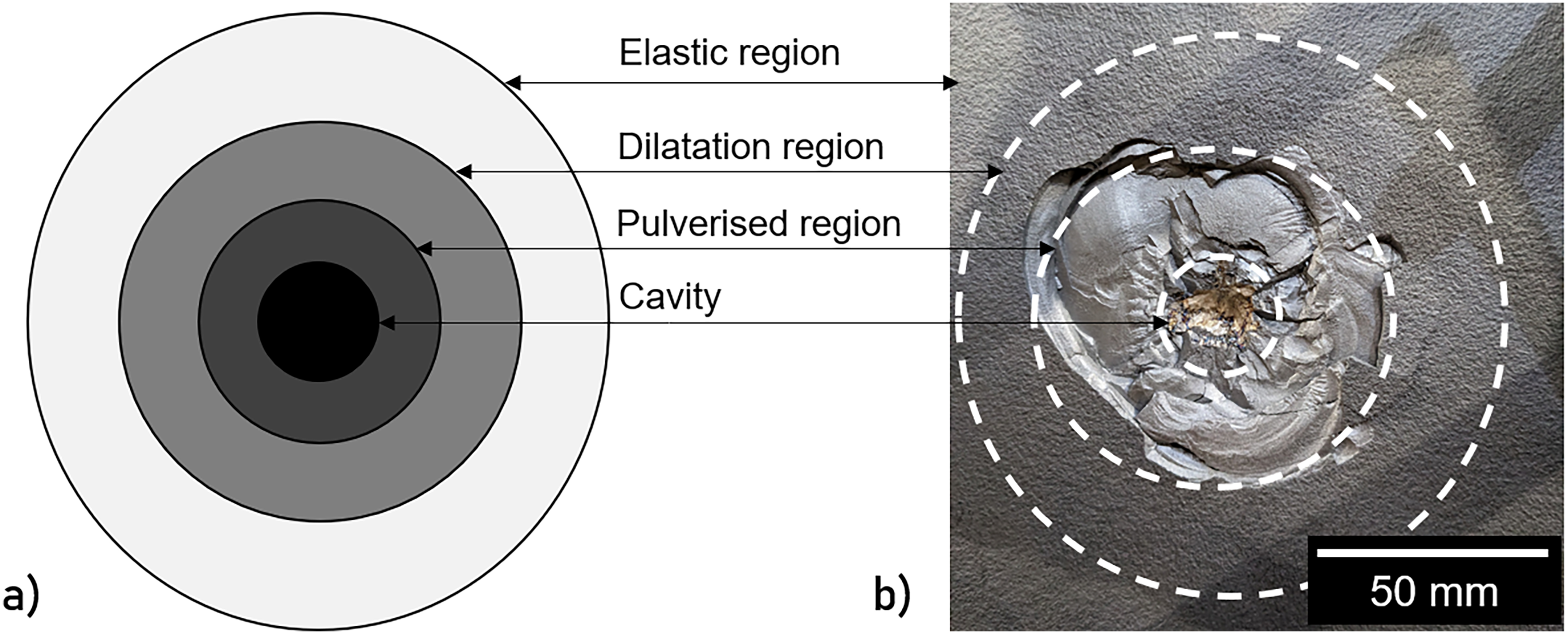
For the control sample FGM MMC in Figure 10, in shot 1, with a velocity of 795 m/s, the clearest example of impact can be seen, with a deeper central impact area (approximately 10 mm diameter and 3 mm depth) corresponding to the penetration of the projectile tip. Surrounding this is a much larger area of front spallation which is estimated to be around 80 mm diameter and 2 mm in depth, all of which is within the hardest layer of 9 wt. % TiB. According to work by Zhang et al., 25 Galanov's model can be expanded for ballistic applications and suggests there are multiple zones to an impact, pictured in Figure 11(a), moving from the cavity, through the pulverised region, dilatation and pore formation region, to the elastic region. These match very well, qualitatively, to the shot profiles seen with the overlaid profile visible in Figure 11(b). The dilatation region is not visible on the surface but was later seen as the region containing the internal stress cracking and voids from the impact seen during analysis in Crack propagation mechanisms section. A similar impact is then seen with a deeper penetration in Figure 10 shot 2 with a velocity of 844 m/s. This additional energy is most visible in the cavity region with the pulverised area being of comparable size. Using qualitative visual inspection upon sectioning, it was observed from the crack propagations that the dilatation regions of these two shots overlapped, demonstrating interaction and resistance to multi-hit impacts with a separation of less than 100 mm from the edge of the previous shot. Shots 6 and 7 then demonstrate the failure modes for this system, characterised by large regions of front spallation again, but with scabbing failure on the rear face, clearly observed in Figure 10. This is likely in part due to the high temperatures the titanium alloy was exposed to during processing, resulting in excessive β grain growth and reduced ductility leading to brittle failure modes. It must be noted however, that the plates structural integrity survived and fully held together even after seven shots and large amounts of damage and material loss. Demonstrated through this is a better inter shot spacing than a monolithic ceramic fronted tile for equivalent threat, providing more potential for this material in multi-hit capacity for real world armour applications or adjusted tile format.
Figure 12 shows the differences in the impact on the ceramic and metallic layers for both the bullet and the plate. The fired cores are displayed in (a) displaying the effect of contact with the reference plate (top) and the FGM control plate (bottom). This clearly demonstrates the fracture of the bullet resulting from making contact with a harder surface, this being the 9 wt.% TiB2 face. The resulting critical failure and fractures in the steel core of the bullet during contact with attack face of the plate, with this TiB inclusion, is due to the plate becoming harder than the bullet if properly processed, seen in Figure 16. Whilst this provides more protection, it also results in higher degrees of damage to the sample. This can be seen in the pulverised regions of the shots on the attack face as well as in the rear face spallation of the TiB plates. In addition, Figure 12(c) shows the impact of a shot into the rear face of the plates, testing for the effect of the orientation of the FGM layers versus bulk properties. This matched visually to the pattern noticed on the attack faces of the Ti-6Al-4V reference plate, though the rear face failure differed with additional spallation. It can also be observed from this rear face shot failure at the comparatively low shot speed of 740 m/s that the directionality of the layering has a significant effect. Also, it may be noted that the ceramic rear face for this shot experienced severe spallation, causing additional damage to the test sheet than a clean metallic penetration. Therefore, these composite materials, having been shown to have severe directionality in their fracture toughness and ballistic properties, must be handled with care to prevent misorientation during production, transport and use.
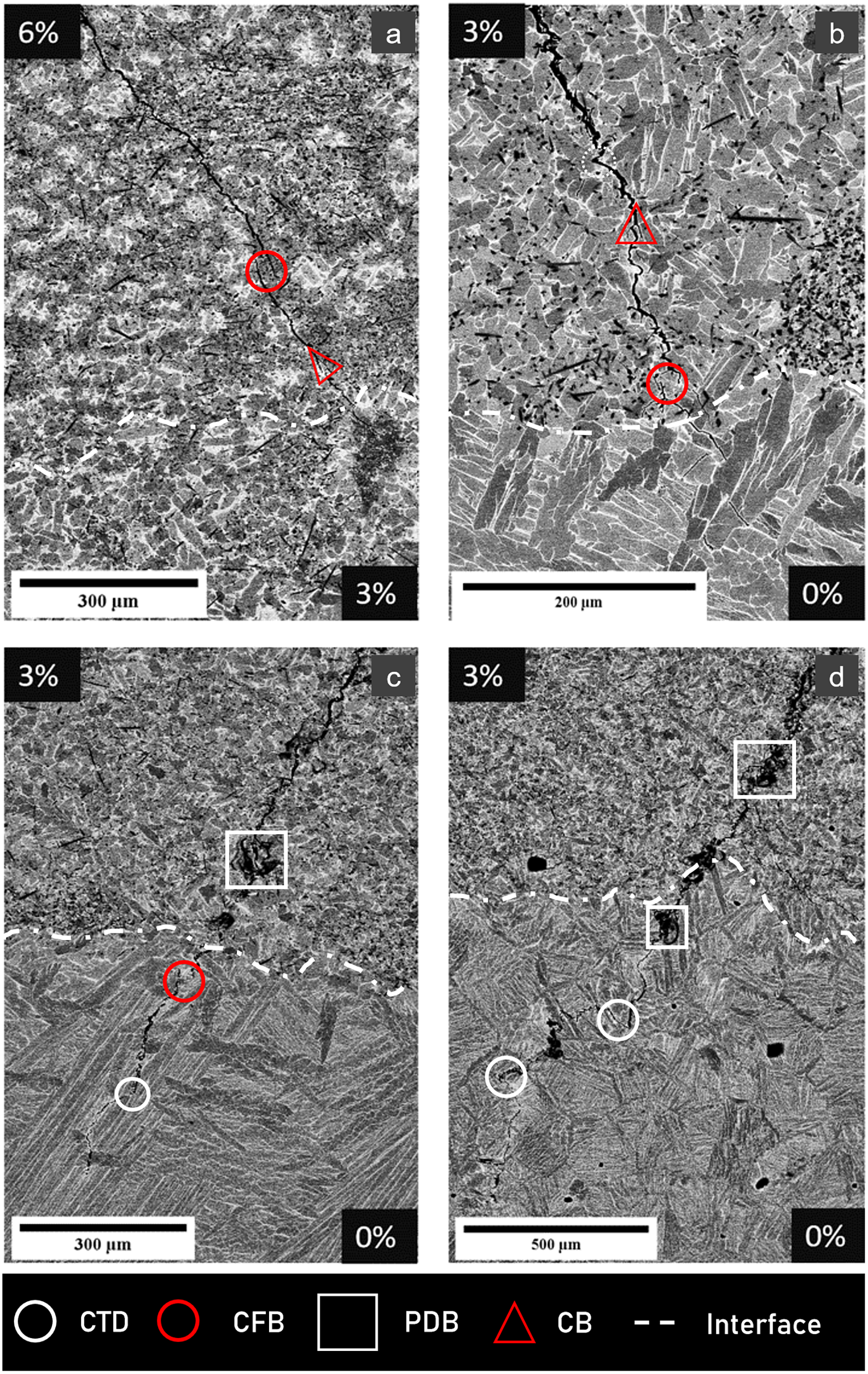
Backscatter electron images of ballistically induced cracks arresting at the interfaces of the functionally graded Ti-6Al-4V + TiB layers with features highlighted in white: crack tip deflection (CTD) in (c) and (d), crack face bridging (CFB) in (a)–(c), particle de-bonding (PDB) in (c) and (d) and crack branching (CB) in (a) and (b). The control, 1350 °C 2 h processed Ti-TiB MMC plates shown here.
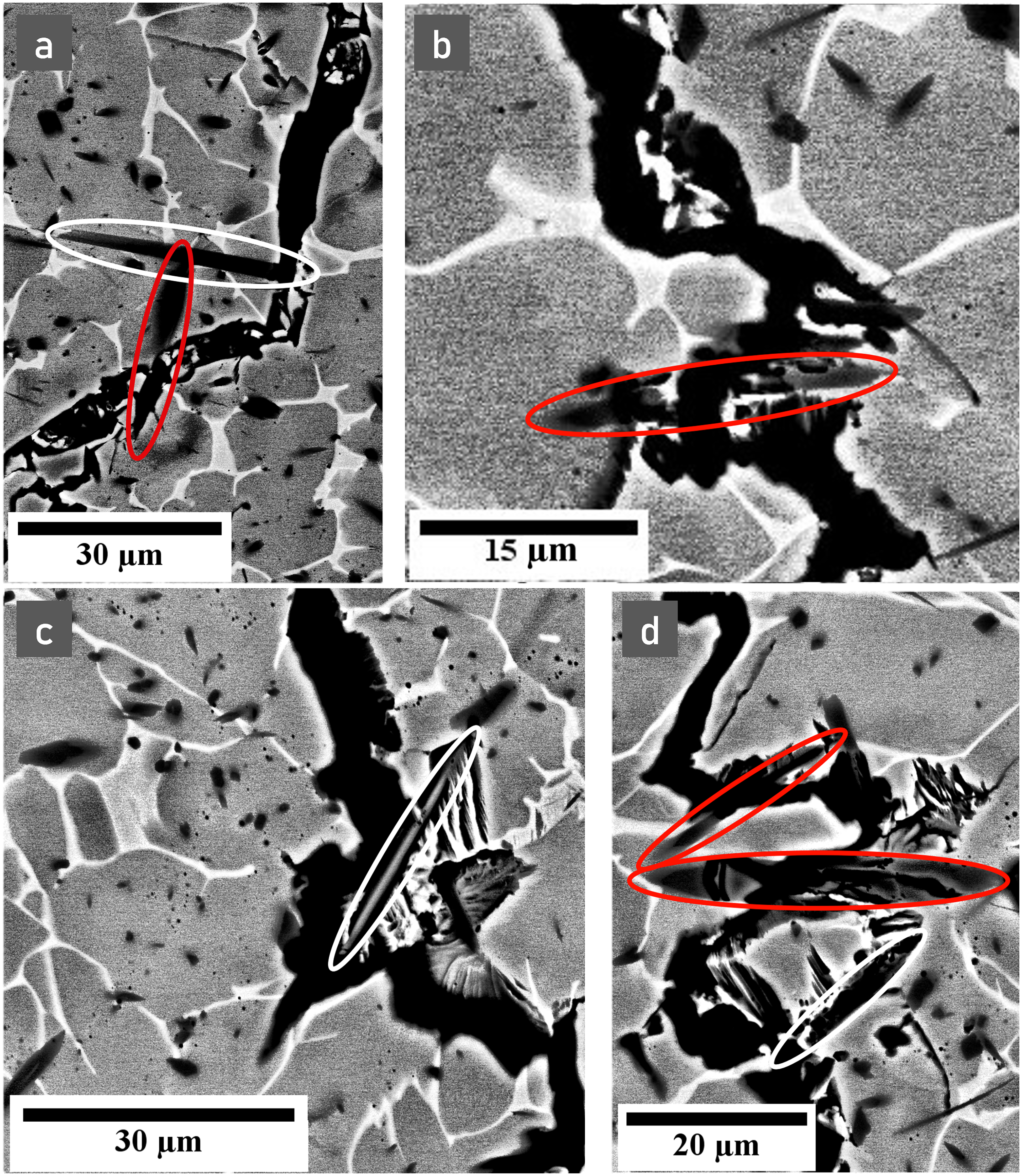
Backscatter electron imaging of cracks interacting with individual TiB needles during propagation showing de-bonding and deflection in white with examples of needle cracking in red. Images (a) and (c) are taken from the control and (b) and (d) from the aperture Ti-TiB MMC plate, both processed at 1350 °C for 2 h.
Testing of micro-hardness in each layer at diagonally traced points from the attack face to the rear face of the sample looking for processing impact on hardness and resulting variance.
The final values presented in Table 2 provide an excellent case for this material system, with the TiB inclusion to the surface attack layers for the control sampleproviding a 27.3 m/s increase in ballistic performance over mil spec titanium currently used for purpose at 833 m/s shown comparatively in Figure 13.
Crack propagation mechanisms
Some of the underlying mechanisms for the improvement in ballistic performance seen from these plates are investigated in more detail here, accounting for both the insertion of the ceramic itself, and the desired reaction with the alloy to create the TiB needle structure. Four primary mechanisms for crack propagation have been observed in the series of primary cracks propagating through the FGM layers, crack face bridging, particle de-bonding or cracking, crack-tip deflection and crack branching. Evidence for these mechanisms has been seen previously in work by Sahragard-Monfared et al., 26 and due to their positive impact on fracture toughening, observing them is a positive indicator for the use of FAST to produce this MMC. Beyond this, it can be noticed that the commonly observed straight fracture is typical of a brittle material in the previous work 26 when TiB wt.% reached higher concentrations with little impact from the TiB needles as predicted, providing more motivation to understand these lower concentration MMC systems. With the lower concentrations the increase in ductility is sufficient for the primary mechanisms to begin to occur and provide high fracture toughness.
The most obvious macroscopic feature of the samples sectioned from near the impact locations was that almost all the residual cracks terminated within a few hundred microns of a layer boundary. Four examples of this can be seen in Figure 14, with the majority of the arrested cracks seen in sectioned samples being between the 3 wt.% TiB layer and the Ti-6Al-4V layer, processed at 1350°C for 2 h. This is due to the increasing ductility in the unreinforced Ti-6Al-4V, allowing more plastic deformation to occur as the matrix absorbs more energy during crack propagation, slowing and eventually halting the crack progression. The consistent scabbing failure mechanism producing shrapnel on the rear face, or ‘scabbing’, of the samples could be assumed to stem from this conical crack propagation through the hard surfaces in a ceramic material. However, with the lower wt.% TiB inclusions in these samples it is more likely to originate in the wave dynamics. When the impact energy is sufficient to penetrate the final ductile layer, this results in the back face ejecting larger pieces of material. It must also be noted that due to the high temperatures required for full consolidation, the grain sizes of the ductile back face will be much larger than ideal fine grain titanium, of an order of magnitude difference at >1 mm in diameter, compared to desirable grain diameters of approximately 100 µm. This increase in size decreases the ductility, likely a primary mechanism in exaggerating this scabbing feature.
The crack features can each be seen in Figure 14, with the crack path becoming strongly affected by the presence of the TiB particles in front of the advancing crack tip. Crack branching and crack deflection can be seen in the 3 wt.% regions of Figure 14(a) and (b), as the cracks are redirected on a small scale around the TiB needles, with the highlighted deflections in the titanium alloy matrix occurring primarily from following larger grain boundary pathways. Crack bridging is also seen occurring primarily in regions of higher TiB or TiB2 concentration, due to the higher hardness and brittleness in those regions, though in (b) an example can be seen of grain boundaries aligning for a similar feature to occur. Delamination, or particle de-bonding is also visible in both Figure 14(c) and (d) and in Figure 15(c), however, the crack face bridging has been the primary observed feature on a larger scale. The delamination has been seen less often than expected due to better consolidation around the needles from FAST than expected. This is likely due to the heat making the titanium alloy matrix more ductile during processing, allowing the needles to expand without external cracking. In this primary mechanism of crack face bridging, the crack can ‘bridge’ the more ductile titanium matrix through the strain field surrounding the crack front, seen near the interface in Figure 14(b) and (c). This causes microcracks ahead of the propagation, and these ‘sealed’ bridges due to plastic deformation and stored energy pressing the material together behind the crack as it passes through. It has also been seen to occur closer to the attack face in (a), where sufficient driving forces can bridge through regions of higher TiB or TiB2 concentration, though with other destructive features present at the impact locations these can be more difficult to distinguish and can be more easily attributed to spallation.
In Figure 15(b) and (d) when the orientation of the needles is perpendicular to the direction of the propagation, the strain field around the crack tip cracked them, or more rarely, resulted in deflection when the approach was angular, as in Figure 15(a). Those more in line with the crack suffered delamination or lesser deflections observed in Figure 15(a) and (c). Some microcracking is also visible in some of the needles along the crack's path (d) which could have been a result of the propagation, absorbing more energy. However, it is also possible that these micro cracks occurred during the cooling process of production, providing early nucleation points for voids which also slow the advance of the fracture. Therefore, regardless of the creation mechanism, their presence in these images is seen as a further positive for the needle's presence in low wt.% TiB MMCs.
With a closer look at the propagation of these cracks two effects these needles have on the micron scale can be seen. In Figure 15(a) and (c), the crack is deviating from its path to circumvent a needle in the plane of the sectioning cut, clearly de-bonding it in Figure 15(c). Mechanistically this is due to the crack propagating along the α–β interface following the lowest energy pathway. A convoluted crack path requires higher energy for fracture, providing the material with a higher fracture toughness resistance, which is therefore beneficial in ballistic applications. It is, as mentioned previously in this section, also observed that in regions closer to the surface attack face, with higher ceramic wt.%, Figure 15(b) and (d), the crack can propagate across, or through, the TiB needles, cracking them and following the prior β grain boundaries. The needles in these images are occasionally deeper into the sample, and less clearly resolved, so there is some potential that the crack has indeed circumvented them in the direction normal to the sectioning cut. However, it is believed that close to the impact points, there is simply sufficient energy for the crack to shear through them following the shockwave in an overall more energy efficient path, at the potential cost of smaller energy losses from avoiding needles in the 9 wt.% layer.
Microhardness
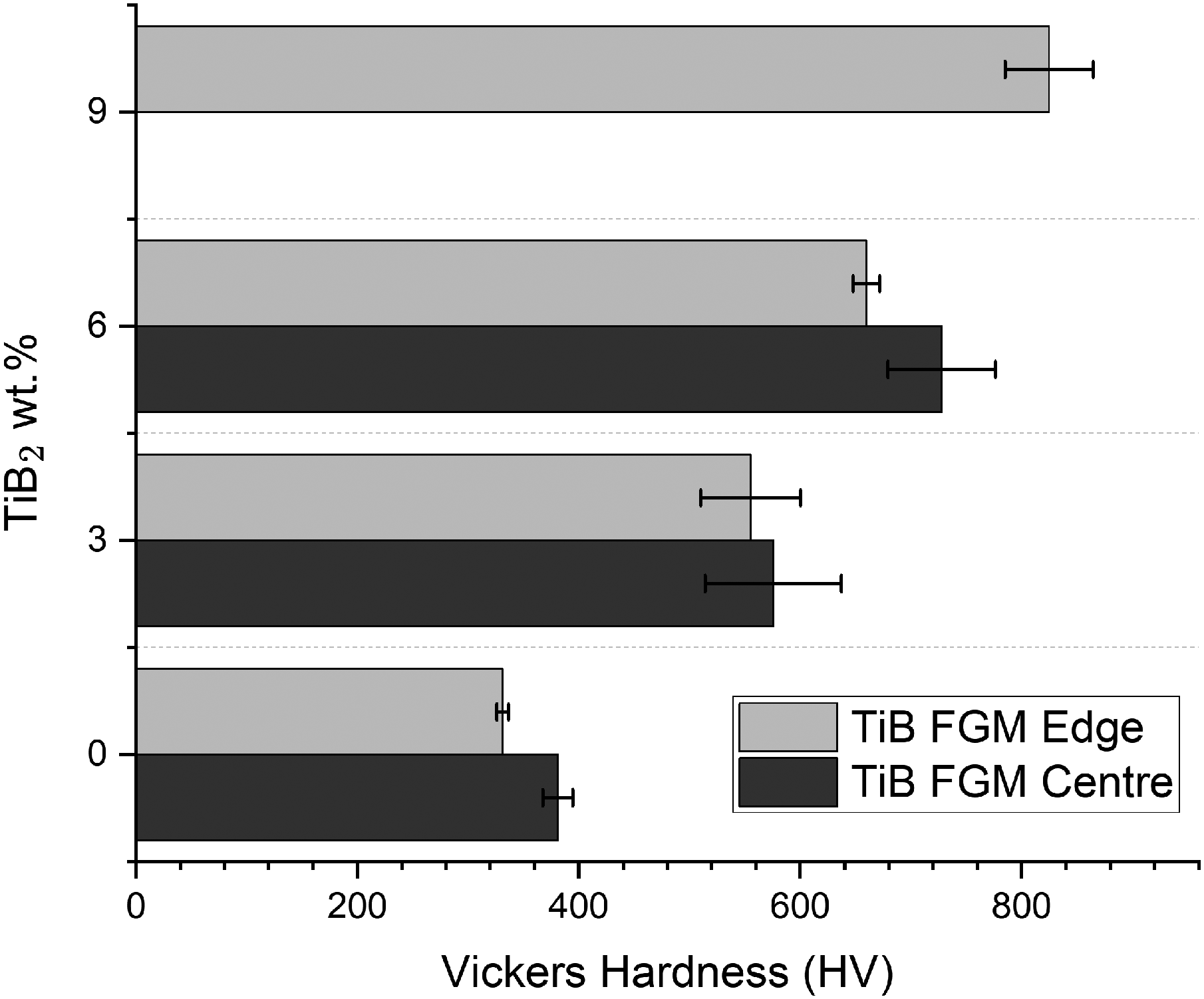
Small scale sample testing initially demonstrated the 9 wt.% layer having a Vickers hardness of between 750 and 900 HV, with testing of the large plates, in Figure 16, show values greater than two times that of the underlying Ti-6Al4V layer. The variance in these MMC layers is significant when processed at low temperatures, causing the poor ballistic performance seen in the aperture sample, though this variance disappears when properly homogenised leaving well distributed needles through the matrix. For these values, multiple points were tested in a grid and averaged to account for the heterogeneously dispersed TiB within the region.
It was decided that due to the thermal sensitivity of the process, and weaker performance of incomplete homogenisation that to obtain increased properties higher processing temperatures were demanded. This was balanced by the ideal requirement for the base Ti-6Al-4V layer to be processed at sub β transus temperatures for maximised ballistic properties, providing a fine process window for this material. It is known that the FAST process has thermal gradients within the sample, and this was accounted for in the choice of processing temperature, though variations can still be seen. These can be seen in Figure 16 and little, if any, difference can be observed in the values compared to the smaller scale testing that is not accounted for with the positioning of the test lines within the layers and potential boron diffusion, implying that the material doped with TiB does not experience much stress hardening. However, it may be possible that during the sectioning and grinding some of the residual stresses were released from within the material as some fragmentation and cracking was noted during this process.
Two main features can be observed, in that the centre of the sample consistently outperforms the edge in terms of hardness and this is further confirmation for the initial hypothesis that thermal gradients in producing samples on this scale has a non-negligible impact on the generation of optimised microstructures for this MMC system. Seen visually in the differing homogeneity in the micrographs from Figure 6. The second, however, is slightly unexpected with the variance in hardness values not being consistent between the testing regions. As the TiB2 reacts with the titanium matrix and forms the TiB needles, homogenising the microstructure of the harder ceramic regions of concentrated TiB2 into a more ductile combination of needles and matrix providing benefits to the systems ballistic resistance. There is however, a potential element of survivor bias, as the materials were tested post ballistic firing it is possible that some of the regions where the microstructures were not homogenised, being too brittle or too soft, were destroyed more easily and the remaining material survived due to their improved strength.
One additional result which can be observed from these microhardness tests approximates the fracture toughness of the material. This is mostly applied to ceramics due to the requirement for the indent to crack the surface of the material and does not generally work for metallic systems. However, for the 9 wt.% layer it appears that cracking was consistent enough due to the increased hardness for a value to be obtained. Using the Miyoshi equation,
27
an averaged value of 24.39 ± 3.399 MPa √m was obtained from five indents, which matched a comparative material from work by Degnah et al.
28
who calculated a fracture toughness of 23 MPa √m for similarly low wt.% β-Ti-TiB composites. This is indeed much higher than the ∼8 MPa √m expected value of pure TiB
Conclusions
The main observation is that the Ti-6Al-4V TiB FGM plate out-performed both the reference Ti-6Al-4V plate and the military specification value for the sample dimensions tested. This demonstrated the overall improvement in performance provided by the functionally graded inclusion of TiB into the titanium alloy matrix for ballistic performance. The plates absorbing between 5 and 7 shots at the required velocity whilst maintaining structural integrity could be seen to indicate the targeted multi-hit capacity, though further testing is required to provide quantifiable data for comparison.
The unique crack mechanisms resulting from TiB needle inclusion have been investigated and their positive impact on the fracture toughness, compared to the monolithic ceramic, was numerically approximated. Combined with the micro-hardness these properties were directly related to their improved ballistic results. These mechanisms, as well as the remarkable grain pinning, revealed through microstructural analysis, are thought to have provided additional resistance to crack propagation and added to the strength of this material system, explaining the material's ballistic success over multiple impacts, as hoped for initially. It was, however, noticed that the high temperature processing required likely resulted in the exaggerated scabbing of the rear face on penetrating shot failures. It was discovered that this was likely due to excessive prior β grain growth within the titanium alloy layer, reducing the ductility of the rear face and its ability to dissipate the energy, resulting in brittle failures.
PSD results of the analysed powders for sample creation demonstrating large variance in size and oversized nature of the rough topography powders.
Ballistic results from range firing using hardened steel slugs.
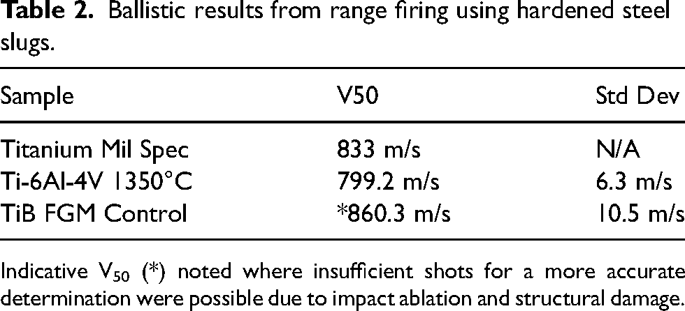
Indicative V50 (*) noted where insufficient shots for a more accurate determination were possible due to impact ablation and structural damage.
Footnotes
Acknowledgements
We would like to thank Sam Lister for their assistance with planning the large sample preparation and Dr Sarah Baker, Dr Matt Lunt and Neil Middleton from Defence Science and Technology Laboratory (Dstl) for their input and support. In addition to the Advanced Metallic Systems Centre for Doctoral Training for further funding our work.
Declaration of conflicting interests
The authors declared no potential conflicts of interest with respect to the research, authorship, and/or publication of this article.
Funding
The authors disclosed receipt of the following financial support for the research, authorship, and/or publication of this article: This work was supported by the Defence Science & Technology Laboratory (Dstl), Science Foundation Ireland (18/EPSRC-CDT/3584) and the Engineering and Physical Sciences Research Council UK (EP/S022635/1). We acknowledge the FAST/SPS capability as part of the Henry Royce Institute (EP/R00661X/1).