
Abstract
A multi-objective robust optimization scheme for the powertrain mount system of an electric vehicle is proposed in this paper. A permanent magnet synchronous motor model is established by taking account of the effects of magnetic saturation and space harmonics, in which the d–q-axis inductance and the flux linkage excited by permanent magnet were obtained by finite element method. The rippled output torque of the permanent magnet synchronous motor mixed with harmonic components is obtained with the New European Driving Cycle as the running condition of the electric vehicle. A six degree-of-freedoms (DOFs) powertrain mount system is established and the response of the system is obtained with the rippled torque as the excitation input. A multi-objective optimization model of the powertrain mount system is built with the stiffness’s of the mounts as the design variables, and with the goal of maximizing the decoupling rates and minimizing the dynamic reaction forces of the mounts acting on the car body. Genetic algorithm is used to conduct the global optimization and all the Pareto optimal solutions are found out based on the optimization theory, and the solution with the optimal robustness of dynamic reaction force is obtained by Latin hypercube sampling method. The results show that with the proposed multi-objective robust optimization scheme applied for the parameters optimization of the motor mount system, the decoupling rates increase obviously, the dynamic reaction force decreases apparently, and the optimization result shows good robustness. The optimization results can make the powertrain mount system of electric vehicles processing of optimal dynamic response characteristics correspondingly.
Keywords
Introduction
The vehicle powertrain, composed of engine, transmission and clutch, is the power source for the vehicles and also one of the main vibration sources in vehicles.
1
In order to isolate the vibration transmitting from powertrain to car body, engine mounts are usually installed between powertrain and car body. The system composed of mounts and powertrain is powertrain mount system. The mounts play an important role in a full-car dynamic system and the schematic diagram of a half-car dynamic model with a powertrain mount system is presented in Figure 1. Appropriate powertrain mount system will on the one hand improve the noise, vibration and harshness (NVH) performance of vehicles, and on the other hand extend the lifespans of the engines and the related components.
2
The schematic diagram of a half-car dynamic model with a powertrain mount system.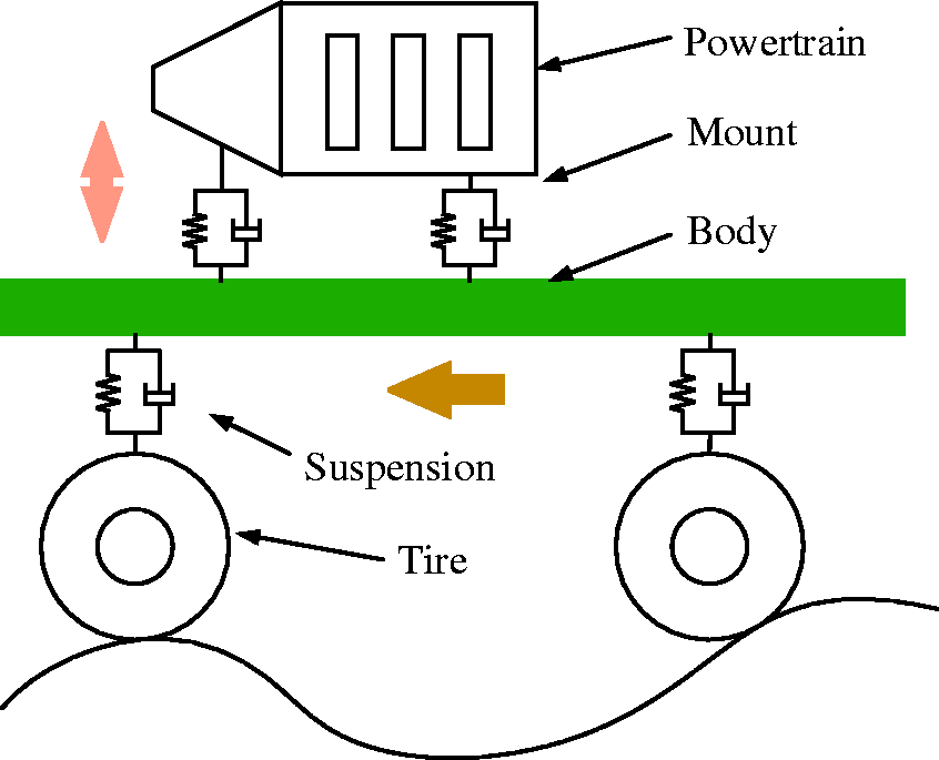
According to the characteristics of the controllability, engine mounts could be categorized into passive mounts (rubber mounts and hydraulic mounts are most common), semi-active mounts and active mounts.3–6 Generally, rubber mounts consist of a metal frame on which the rubber is adhered either through adhesives or during vulcanization. Due to the advantages of low cost and simple structure, rubber mounts are the most widely used engine mounts.7,8 The key step for the design of rubber mounts is the parameters match of their stiffnesses. The rubber mounts with appropriate stiffnesses cannot only attenuate the vibration of the engine transmitting to the elastic foundation (such as the frame and the body) effectively, but can also decrease the unwanted impacts of the excitation from roads and the wheels acting on the body.
In recent years, there have been more and more literature on the vibration characteristic analysis and robust optimization design on the rubber mounts-based powertrain mount system.9–15 Considering the influence of the elastic body, 9 built a multi-body dynamics model of powertrain mount system containing auxiliary frame and its sleeve. Genetic algorithm was utilized to optimize the stiffnesses and locations of the mounts with the target of minimizing the force acting on the auxiliary frame. To improve the NVH performance at idle speed of internal combustion engine vehicles, Qatu et al. 8 optimized the stiffnesses of the mounts based on the established six DOFs powertrain mount system. The experimental results showed that the NVH performance at idle speed was improved obviously. Hu and Singh 12 established a powertrain mount system model with consideration of the elastic foundation and optimized the stiffnesses of the mounts aiming at maximizing decoupling rate of the torque axis. On the robustness optimization design of the powertrain mount system, based on the conventional pendulum mounting system of a front wheel drive vehicle with a transversely four-cylinder engine, Courteille and Mortier 13 adopted a multi-objective genetic algorithm for the solution of the multi-objective robust optimization problem at idle speed. Based on interval distribution, Wu 14 built an optimization model of powertrain mount system and the parameters of the powertrain mount system were optimized correspondingly. In order to improve the robustness of the powertrain mount system of the internal combustion engine vehicles, Xie et al. 15 combined the robust design with multi-objective optimization and proposed a robust optimization design scheme. The simulation results showed that the optimized results had good robustness.
However, as compared with the running conditions of the powertrain mount systems of traditional internal combustion engine vehicles, there are big differences in the running conditions of the powertrain mount systems of electric vehicles (i.e. motor mount system). On the one hand, as the mass of the motor mount system is smaller than the internal combustion engine mount system, when subjected to a same excitation, motor mount system will vibrate more intensely. On the other hand, since the powertrain mount systems of electric vehicles have no idle speed state, the speed of the motor will go through from zero to the maximum speed, and the excitation frequency will pass through the natural frequencies of the powertrain mount systems. Hence, when the excitation frequency passes through the natural frequencies, the transient response of powertrain mount systems will be amplified and deteriorated. In addition, due to faster torque response speed of motor, it is easier to generate a transient impact on the vehicle and increase the transient vibration of the vehicle. What’s more, because the inductance of the permanent magnet synchronous motor (PMSM) and flux linkage produced by permanent magnet change with the saturation degree of magnetic circuit, and it also contains a lot of space harmonics in rotor magnetic field, the output torque of the PMSM will be mixed with a certain of fluctuant components.16–18 The rapid and rippled torque transmitted to the body is more likely to lead to longitudinal and vertical vibration of the vehicles.
Hence, how to attenuate the vibration caused by the PMSM is an urgent problem and has been paid much attention in recent years.19–21 To attenuate vibration of the passenger seat, Guclu and Gulez 19 studied the dynamic behaviour of an eight DOFs vehicle model having active suspensions and the vibration is suppressed effectively using a neural network controller. Torregrossa et al. 20 proposed a three-dimensional finite element modal analysis method to reduce the vibration radiated by the PMSM and the vibration is controlled by optimizing the structure parameters of the PMSM. Chen et al. 21 calculated the electromagnetic torque excitation caused by the torsional displacement using electromechanical coupled dynamic equations and studied the nonlinear torsional vibration characteristics of the PMSM. Besides, many researchers have also been trying to proposing active mitigation of the vibration. Ayana et al. 22 designed an effectively active torque cancellation scheme to reduce transmitted vibration by an order of magnitude at targeted frequencies which does not require the over sizing of machine or power electronics components. To quickly evaluate the electromagnetic vibration emitted by a PMSM in a fractional-horsepower drive, Torregrossa et al. 23 proposed a novel approach based on field reconstruction method, which reduce the vibration in the targeted machine by 35%.
According to the above researches, it can be found that the existing solutions for the vibration attenuation of the electric vehicle focus on changing the motor structure parameters, optimizing the motor control algorithms and applying active actuators. Nevertheless, in some cases, those methods might be useless and too expensive for the design of the motor mount system. For example, the traditional design method for internal combustion engine vehicles might be invalid to mitigate the transient vibration of the powertrain mount system. Just like the parameter design for the powertrain mount system of traditional internal combustion engine vehicles, optimizing the mount stiffness may be an efficient and simple method. However, how to optimizing the mount stiffness of the motor mount system with consideration of the characteristics of the output torque of the motor and the uncertainty of the mount remain to be discussed.
In this article, a multi-objective robust optimization scheme for motor mount system is proposed and applied in the optimization design process of the powertrain mount system of an electric vehicle. The remainder of the paper is organized as follows. In section ‘Torque ripple model’, a nonlinear PMSM model is established by taking account of the effects of magnetic saturation and space harmonics, and the rippled output torque mixed with harmonic components is obtained. A six DOFs dynamic model of motor mount system is established, and the decoupling rates of the six DOFs and the dynamic reaction forces of the mounts acting on the body are obtained correspondingly in section ‘Vibration characteristic of the powertrain mount system’. In section ‘Multi-objective robust optimization design of powertrain mount system’, with the stiffnesses of the mounts as the design variables and considering their uncertainties, and with the decoupling rates, the dynamic reaction force and its robustness as design objectives, a multi-objective robust optimization design of the motor mount system is carried out to obtain better NVH performances of the electric vehicle. In section ‘Optimization results’, the optimization results are calculated. Finally, conclusions are presented in section ‘Conclusions’.
Torque ripple model
Linear model of PMSM
A typical structure of a PMSM is shown in Figure 2. As seen from Figure 2, a PMSM is composed of a stator, a rotor, permanent magnets and windings. The rotor rotates with the periodically changes of the current of the windings.
16
As PMSMs have advantages of high energy density, wide speed range, large torque moment of inertia and good efficiency, they are one of the most widely used motor types in electric vehicles.
24
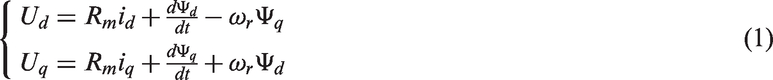
Accurate PMSM model is a necessary prerequisite to analyse the vibration characteristic of the motor mount system. However, the commonly used linear model of PMSM is established with ignoring magnetic saturation and assuming that the magnetic field produced by the permanent magnet is sinusoidally distributed in the air gap.
16
The linear model of PMSM can be expressed as
The model of a PMSM.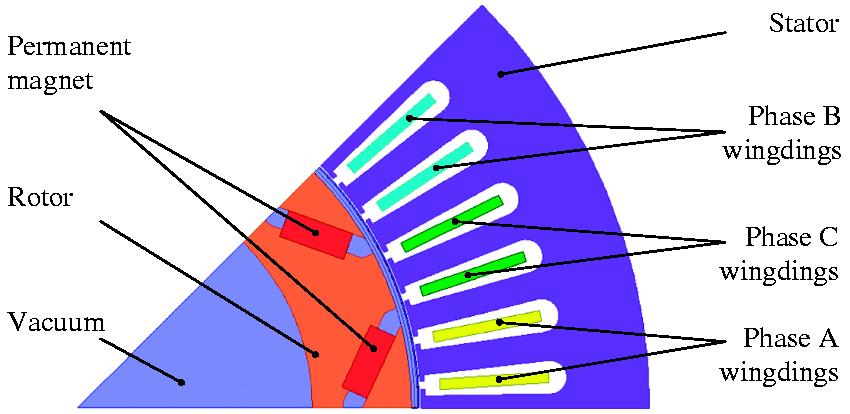


Nonlinear model of PMSM
During the running process of PMSM, the magnetomotive force Fm produced by permanent magnet is a constant, the relationship between total magnetic flux

In practical applications, ferromagnetic materials as well as magnetic circuit will have nonlinear characteristics, i.e. the nonlinear properties of B–H curve of ferromagnetic materials will lead to the relative magnetic permeability

In the linear model of PMSM expressed by equation (1), the distribution characteristics of the magnetic field produced by the permanent magnet in the air gap is simplified as sinusoidal distribution. However, because of the manufacturing defect and the technological limitation, the magnetic field produced by permanent magnet has large harmonic components. That is to say, the magnetic field produced by permanent magnet is not sinusoidally distributed in the air gap, but superimposed by the fundamental wave and a series of space harmonic components changing with locations.
17
For example, the magnetic flux produced by permanent magnet in phase A can be expressed as

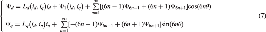
By substituting equation (7) into equation (1), the nonlinear model of PMSM can be obtained


Comparing equation (9) with equation (3), it can be found that the output torque of the PMSM contains high order of harmonic components when taking account of the influences of magnetic saturation and space harmonics. In other words, the output torque of PMSM will be rippled.
Output torque of PMSM
Because the amplitudes of high order of harmonic flux linkages produced by permanent magnet are very small, the influence of the magnetic saturation on high order of harmonic flux linkages can be ignored. In other words, the high order of harmonic flux linkages produced by permanent magnet can be regarded as constant values. In the light of the characteristics of the PMSM applied in this study, the output torque of the PMSM can be obtained according to equation (9). It should be noted that
Parameters of the PMSM.
PMSM: permanent magnet synchronous motor.
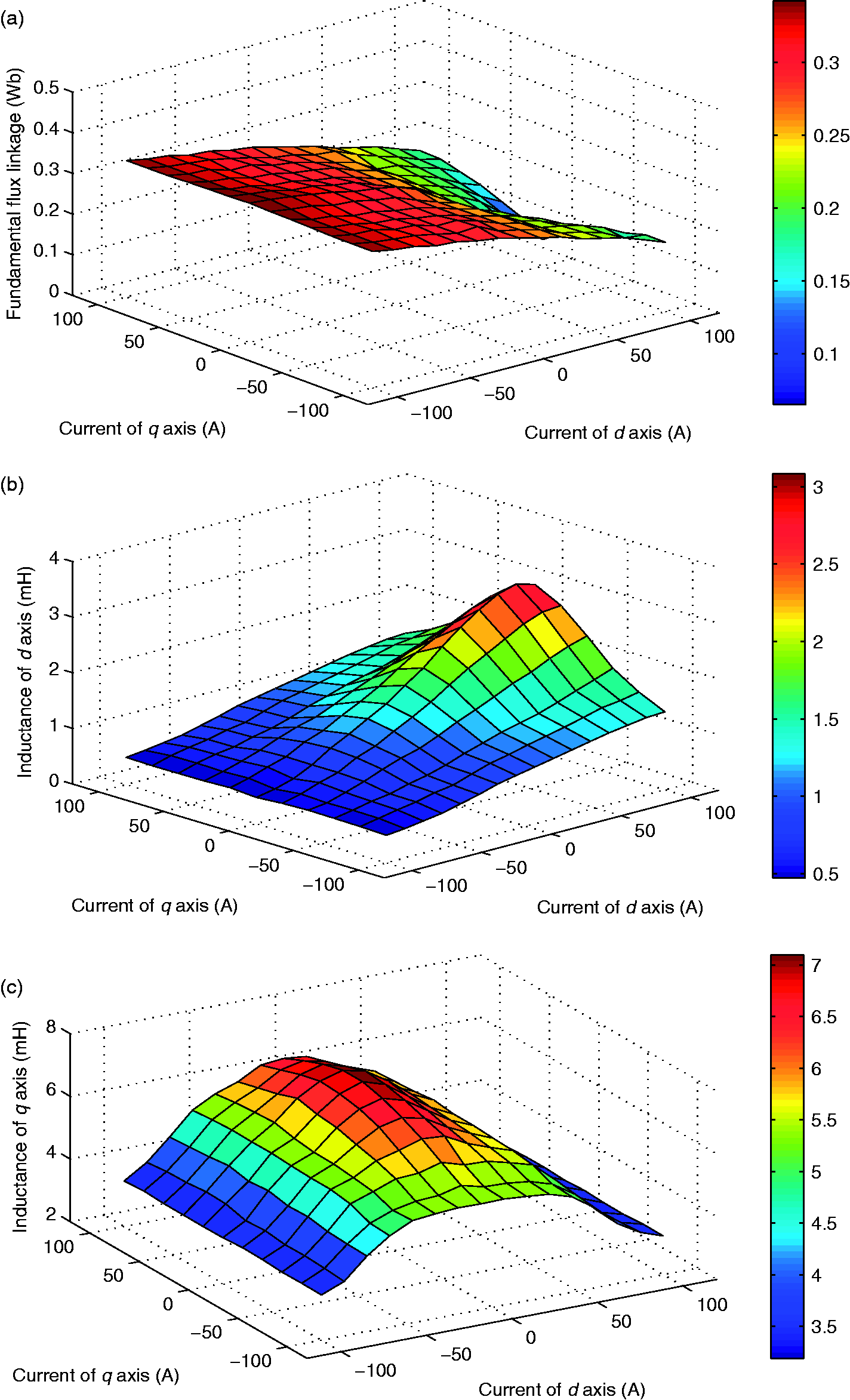
The relationships between
In order to represent the practical characteristics of the output torque of the PMSM accurately, the New European Driving Cycle (NEDC) is applied as the running condition of the electric vehicle because NEDC is one of the most typical running conditions. In the light of the specified operation conditions, the vehicle speed and the driver demand torque both can be obtained correspondingly. Then in accordance with the control principle of the MTPA,
25
id and iq can be calculated, and Output torque of the PMSM. (a) Output torque of the PMSM in time domain; (b) output torque of the PMSM in frequency domain.
Figure 4(a) and (b) presents the rippled torque of the PMSM in time domain and in frequency domain, respectively. It can be seen from Figure 4(a) that the output torque of the PMSM contains obvious harmonic components. Taking the running condition of 50–63 s, for example, the output torque of the PMSM obtained from ideal linear model is 43.3 Nm. However, the output torque of the PMSM with consideration of the effects of magnetic saturation and space harmonics fluctuates between 38.5 and 48.1 Nm with a fluctuation range of 11.1%. There is a big difference between the constant output torque obtained from the linear model and the rippled output torque calculated from the nonlinear model of the PMSM. As seen from Figure 4(b), the output torque of the PMSM distributes over a widely range in frequency domain from 0 Hz to around 1000 Hz. Overall, the amplitude of the output torque at low frequency (less than 30 Hz) is bigger than that at high frequency. It is because that when the vehicle running in the condition of NEDC, the vehicle continuously runs through the process of start, speed-up, constant speed, speed-down and stop. When the vehicle speed is low especially in the process of speed-up, it need a relatively large torque, so the saturation degree of magnetic circuit is high according to Figure 3, which results in the fluctuation range of the output torque at low speed is obvious than that at high speed. Hence, as seen from Figure 4(a) and (b), the rippled torque will produce different impacts on the motor mount system and can represent the actual load conditions of the motor mount system more precisely.
Vibration characteristic of the powertrain mount system
Dynamic model of powertrain mount system
The natural frequencies of powertrain mount system are less than 30 Hz in general, and they are far less than the flexible-mode frequencies of powertrain. Therefore, the powertrain mount system can be simplified as a six DOFs rigid model, and the rubber mounts are simplified as three-direction orthogonal damping springs.
2
The dynamic model of powertrain mount system is shown in Figure 5.
The dynamical model of the powertrain mount system.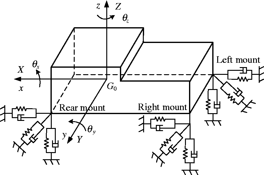
As shown in Figure 5, 


According to equations (10) to (12), it can be derived that when the powertrain mount system vibrates in its jth mode, the kinetic energy of the kth generalized coordinate can be expressed as


According to equations (13) and (14), when the powertrain mount system vibrates in the jth mode, the decoupling rate of the kth generalized coordinate can be obtained.

Besides, z-DOF is the sensitive direction of human body,
The parameters of the powertrain.

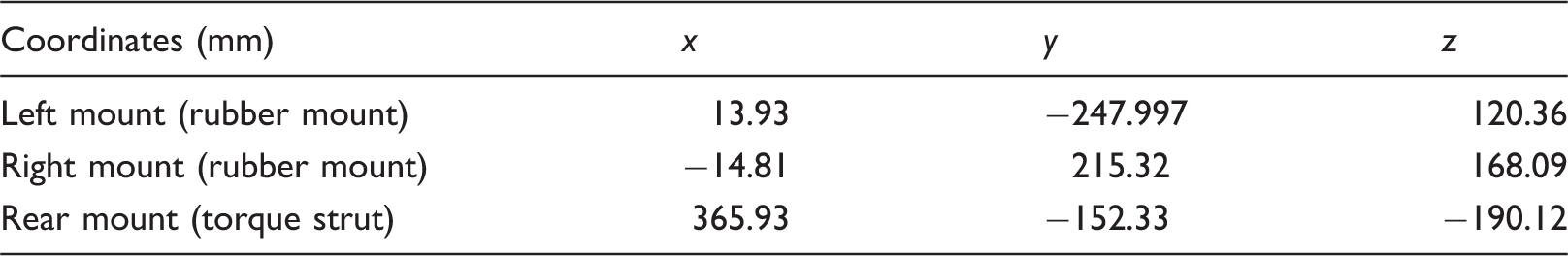
The installation positions of the mounts (the mounts are all installed horizontally).
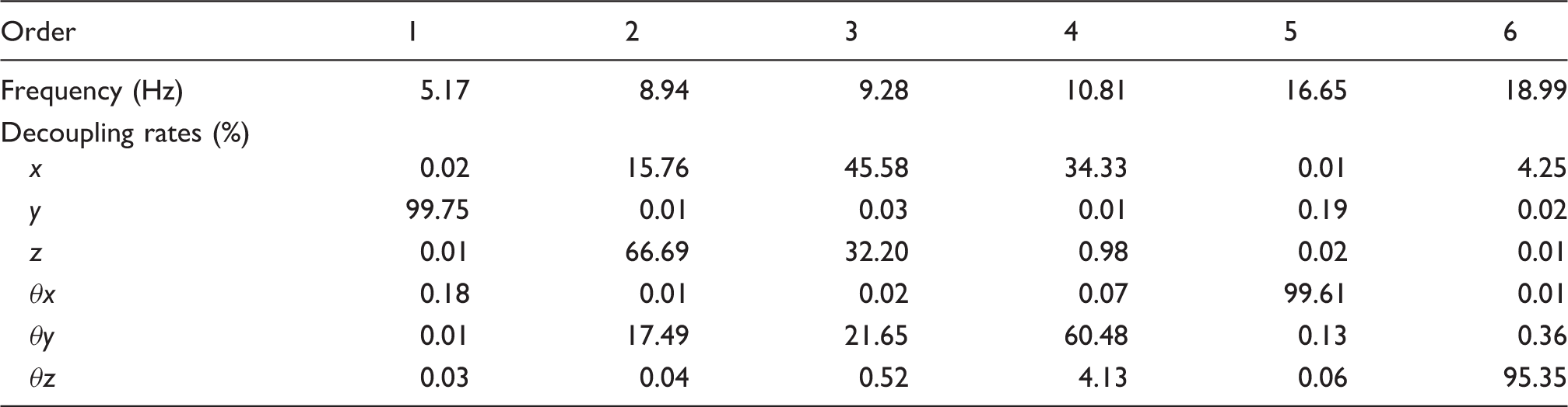
The natural frequencies and decoupling rates of the powertrain mount system before the optimization.
In order to evaluate the vibration response of the powertrain mount system, a MATLAB/Simulink dynamic model of the powertrain mount system is established and shown in Figure 6.
The Simulink model of the powertrain mount system.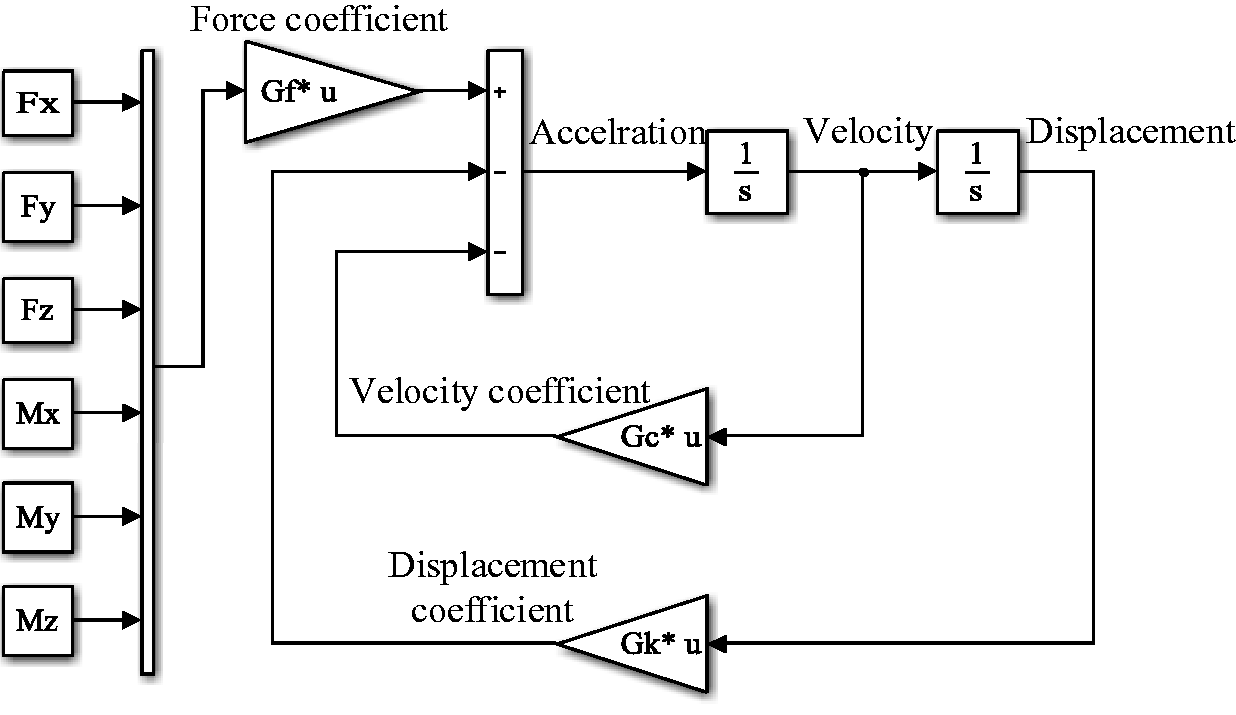
Response of the powertrain mount system
In this study, the motor mount system is installed transversely, meaning the output torque of the PMSM points towards the side of the vehicle. That is to say, the excitation of the powertrain mount system is around The dynamic reaction force of the mounts acting on the body.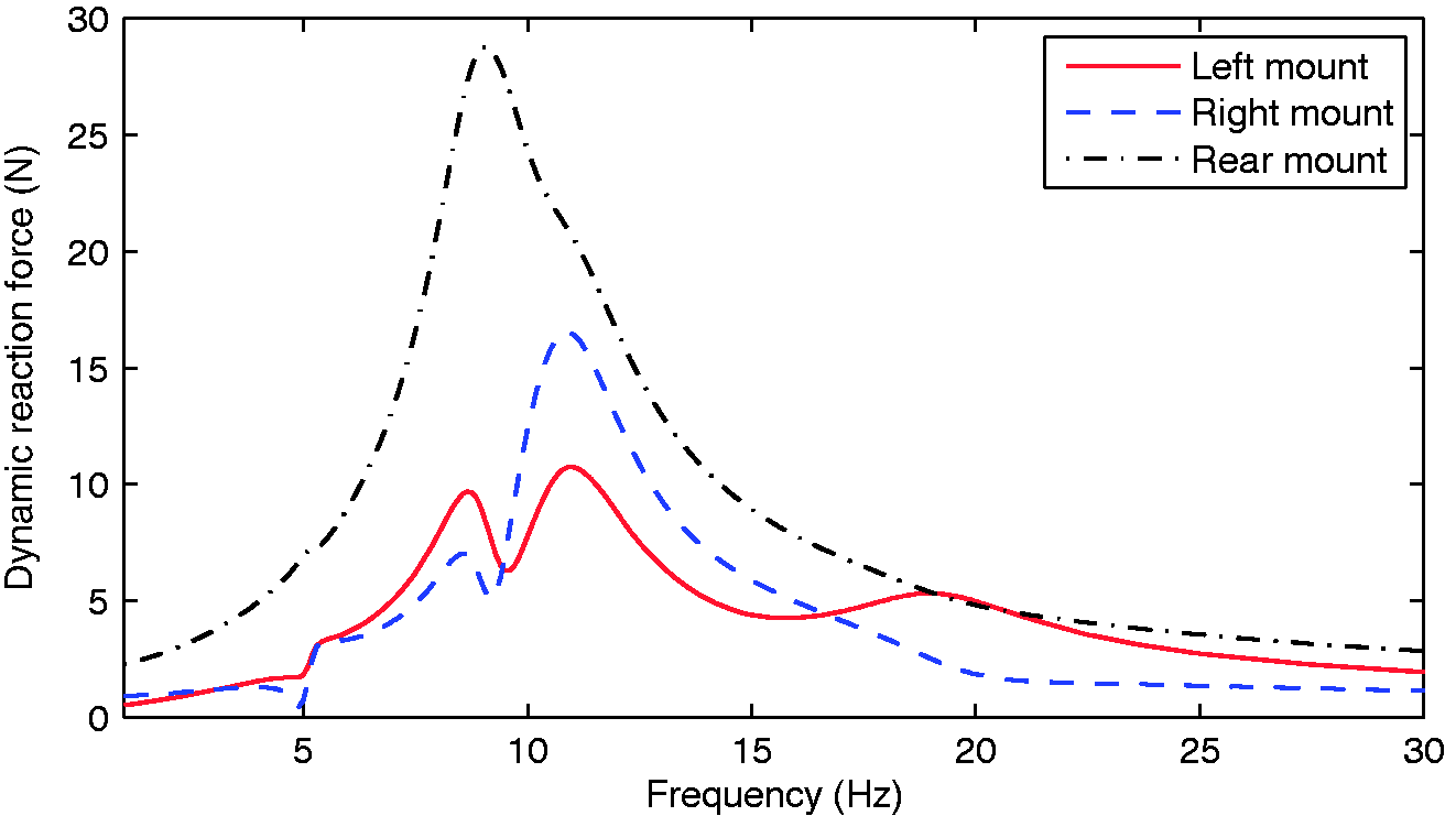
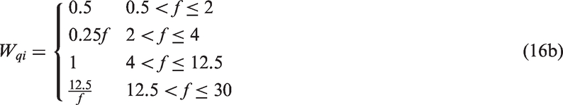
As human body is sensitive to different frequencies of vibration, the weighted value of the dynamic reaction force of the mounts acting on the body within a frequency range of 0–30 Hz is calculated. The weighted dynamic reaction force is adopted as the index to evaluate the influence of the vibration of the powertrain mount system on human body.
27
The weighted dynamic reaction force can be expressed as

Multi-objective robust optimization design of powertrain mount system
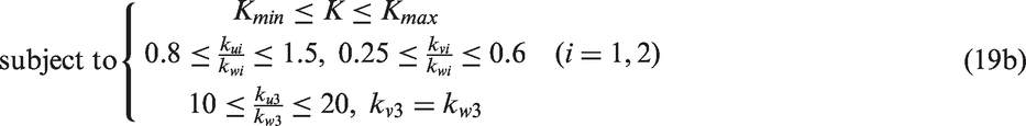
According to Table 4, the decoupling rates of the powertrain mount system are not high and its vibration energy couples seriously. It will deteriorate the vibration of the powertrain mount system seriously. Therefore, the parameters of powertrain mount system needed to be optimized. As the installation positions of the mounts and the inertia moments of the powertrain are difficult to be changed once the design process is completed. Meanwhile, the stiffnesses of the mounts are relatively easy to be changed. Therefore, the three-direction stiffnesses of each of the mount are selected as the design variables. It should be noted here, the left mount and right mount are rubber mounts and as the inherent characteristics of the rubber material, the three-direction stiffnesses are not completely independent and are needed to satisfy certain proportional relations,
27
that is


As the rear mount is a torque strut, according to the characteristics of torque strut,
28
its three-direction stiffnesses are needed to satisfy the following relationships


The powertrain mount system will be influenced by some kinds of uncertainty factors during the running process of the vehicle, and the parameters of mounts will also be influenced by various uncertainty factors during the manufacturing process. The parameters of the powertrain mount system are not all equal to the optimal target values, and they will be statistically distributed near the target values. Therefore, in order to satisfy the demand of engineering application, the optimization results are still needed to possess good robustness. In this study, a multi-objective robust optimization scheme of powertrain mount system is proposed and can be expressed as


According to equation (19), it can be known that the optimization model of the powertrain mount system is a multi-objective optimization problem.
Improved elitist non-dominated sorting genetic algorithm-II (IENSGA-II) is an improved algorithm based on non-dominated sorting genetic algorithm-II (NSGA-II).
30
By introducing a distribution function to constrain the number of parent elitist solutions, IENSGA-II can improve the population diversity. The algorithm not only can ensure that the search direction move towards the true Pareto optimal surface to obtain the evenly distributed solutions, but also can prevent the premature convergences of the populations. Therefore, IENSGA-II is applied for the multi-objective optimization of the powertrain mount system. The evolution process of the IENSGA-II is shown in Figure 8.
The evolution process of the IENSGA-II.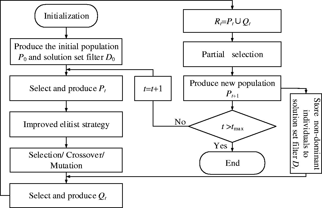
It can be seen from Figure 8, firstly, the initial population P0 is randomly generated and the population size is N, the solution set filter D0 is initialized simultaneously and the iteration number t is set to 0. The infeasible degrees of all individuals of current population are calculated and a new population Pt is generated correspondingly. Non-dominated sorting method is applied for Pt and a certain number of the optimal individuals in the parent population Pt is selected to carry out a tournament selection with the individuals of the solution set filter Dt. The subpopulation Qt is generated based on the arithmetic operators and polynomial mutation operators. By combining the subpopulation Qt and the parent population Pt, a new population Rt is generated. Combining with the value of the objective function, the partial selection method is applied according to the non-dominated sorting level and the congestion degree. A total number of individuals of N are selected to form a new population Pt + 1. The first layer of the non-dominated individuals is stored into the solution set filter Dt and the dominant and intensive individuals in the solution set filter Dt is deleted simultaneously to guarantee that the individuals could distribute evenly in the filter. At last, the iteration number t is judged, and the algorithm will terminate if the iteration number t satisfies the maximum iteration number tmax. Otherwise, t = t + 1, a new population Pt is generated sequentially.
Figure 9 presents the process of the proposed multi-objective robust optimization scheme. It can be seen from Figure 9 that the optimization scheme can be divided into three processes. Firstly, based on the characteristics of the output torque of the PMSM and the vibration characteristics of the motor mount system, a multi-objective model of the motor mount system is established. IENSGA-II is used to conduct global optimization and all the Pareto optimal solutions satisfying the requirements of the deterministic multi-objective optimization are found out based on the optimization theory. Then Latin hypercube sampling method is applied for sampling each set of the Pareto optimal solutions and to find the optimal robust solution in all the Pareto optimal solutions. As a consequence, the optimal solution with perfect vibration performance and good robustness can be obtained based on this scheme.
The optimization process of the proposed schemes.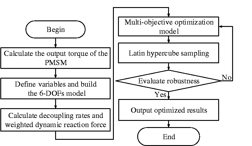
Optimization results
Aiming at the established dynamic model of powertrain mount system, by applying the proposed multi-objective robust optimization scheme, a multi-objective robust optimization model of powertrain mount system as expressed by equation (19) is established. The stiffnesses of the mounts are selected as the design variables, the maximum decoupling rates of the six DOFs, the minimum dynamic reaction force of the mounts acting on the body and the good robustness of the dynamic reaction force are selected as the design objectives. The population size is set as 20, the maximum iteration is set as 60, the crossover probability is set as 0.9. With the application of the IENSGA-II, all the Pareto optimal solution set can be obtained and shown in Figure 10. All the Pareto optimal solutions can achieve high decoupling rates of the six DOFs; however, the single solution result with optimal robustness should then be selected with Latin hypercube sampling method.
The Pareto optimal solution set.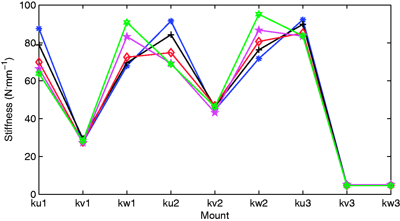
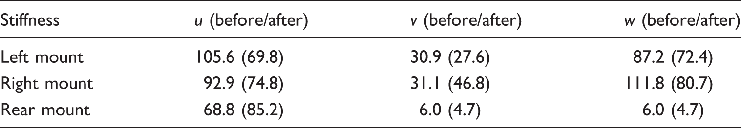
The stiffnesses of the mounts before and after the optimization (N/mm).
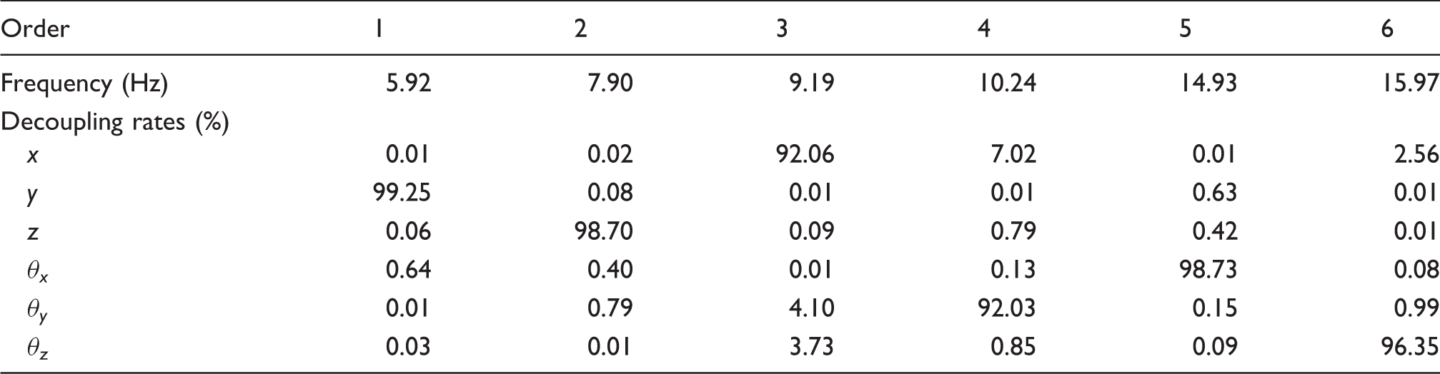
The natural frequencies and decoupling rates of the powertrain mount system after the optimization.
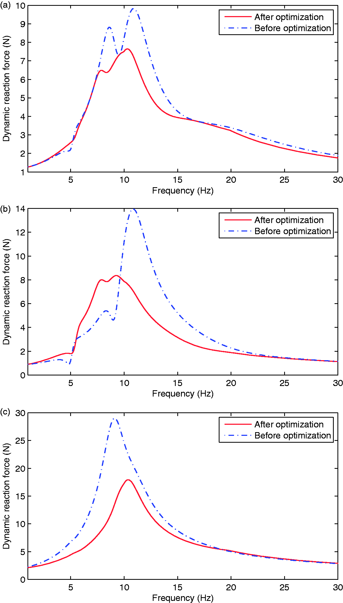
The dynamic reaction force of the mounts acting on the body. (a) The dynamic reaction force of the left mount acting on the body; (b) the dynamic reaction force of the right mount acting on the body; (c) the dynamic reaction force of the rear mount acting on the body.
As shown in Table 5, the decoupling rates of the six DOFs are all larger than 90%, and the decoupling rates have an obvious increasement as compared with the results before the optimization. It can be seen from Figure 11, the dynamic reaction force of the left mount acting on the body in frequency domain deceases from 9.8 N to 7.6 N, the dynamic reaction force of the right mount acting on the body in frequency domain deceases from 13.9 N to 8.2 N, and the dynamic reaction force of the rear mount acting on the body in frequency domain deceases from 27.9 N to 17.3 N. The dynamic reaction force of each mount acting on the body deceases obviously, which means that the optimal solution has a perfect vibration attenuation effectiveness.
By applying Latin hypercube sampling method for sampling the stiffnesses of the mounts, it can be obtained that before the optimization, the mean value of the weighted dynamic reaction force of the mounts acting on the body
Figure 12 presents the probability density distribution of the dynamic reaction force of the mounts acting on the body before and after the optimization. As shown in Figure 12, the maximum probability density before the optimization is 0.051 and the maximum probability density after the optimization is 0.091, which means that the probability density improves 87% after the optimization. It can also be seen that the probability density curve after the optimization is slenderer than the curve before the optimization, which indicates that the powertrain mount system has a better robustness when optimized by the proposed robust optimization design scheme.
The probability density distribution of the dynamic reaction force of the mounts acting on the body.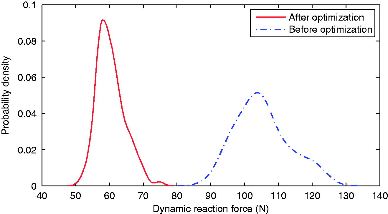
Conclusions
In this paper, a multi-objective robust optimization scheme is proposed and applied for the optimization design of powertrain mount system for an electric vehicle. The actual output torques of the PMSM of the electric vehicle under the NEDC running condition were obtained by taking account of the influences of magnetic saturation and space harmonics on the d–q-axis inductance and the flux linkage excited by permanent magnet. A six DOFs motor mount system was established and the vibration response was obtained with the actual output torque as excitation. A multi-objective optimization model of the powertrain mount system was built to improve its vibration performances. Genetic algorithm was applied to conduct global optimization and all the Pareto optimal solutions were found out, and the solution with optimal robustness of dynamic reaction force was obtained by Latin hypercube sampling method. The results showed that: (i) the actual output torque of the PMSM with consideration of the influences of magnetic saturation and space harmonics on the d–q-axis inductance and the flux linkage fluctuates with a range of 11.1%. The output torque of the PMSM distributes over a widely range in frequency domain and the amplitude of the output torque at low frequency (less than 30 Hz) is bigger than that at high frequency; (ii) with the proposed optimization scheme, the decoupling rates of the six DOFs are all larger than 90%, with an obvious improvement as compared with the results before the optimization. The dynamic reaction forces of the mounts acting on the body are attenuated effectively and the robustness of the dynamic reaction forces has an improvement of 48%. The proposed multi-objective robust optimization scheme is effective both on the improvement of vibration attenuation effectiveness and vibration robustness of the powertrain mount system of the electric vehicle. The proposed scheme has guiding significance on the design of the powertrain mount system of the electric vehicle in the practical engineering.
Footnotes
Declaration of conflicting interests
The author(s) declared no potential conflicts of interest with respect to the research, authorship, and/or publication of this article.
Funding
The author(s) disclosed receipt of the following financial support for the research, authorship, and/or publication of this article: This work was supported by the Pre-Research Foundation of China during the 13th Five-Year Plan Period (Grant No. 6140240040101), the Key Research and Development Projects of Anhui Province (Grant No. 1704E1002211), and the Fundamental Research Funds for the Central Universities (Grant No. JZ2017HGTB0202).