
Abstract
In this article, an experimental investigation of the detection of a gyroscopically induced vibration and the balancing control performance of a single-wheel robot is presented. The balance of the single-wheel robot was intended to be maintained by virtue of the gyroscopic effect induced from a highly rotating flywheel. Since the flywheel rotates at a high speed, an asymmetrical structure of a flywheel causes an irregular rotation and becomes one of the major vibration sources. A vibration was detected and suppressed a priori before applying control algorithms to the robot. Gyroscopically induced vibrations can empirically be detected with different rotational velocities. The detection of the balancing angle of the single-wheel robot was accomplished by using an attitude and heading reference system. After identifying the vibrating frequencies, a notch filter was designed to suppress the vibration at the typical frequencies identified through experiments. A digital filter was designed and implemented in a digital signal processor(DSP) along with the control scheme for the balance control performance. The performance of the proposed method was verified by the experimental studies on the balancing control of the single-wheel robot. Experimental results confirmed that the notch filter designed following the detection of the flywheel’s vibration actually improved the balancing control performance. A half of the vibration magnitude was reduced by the proposal.
Keywords
Introduction
Mechanically induced vibrations are always present in dynamical systems, and they are considered as one of the major causes of degrading system performances. Such vibrations even cause instability. Since suppressing vibration is an important task to improve performance, techniques have been investigated for various purposes in industrial systems.
There are usually three steps to address vibration. The first step is to identify the typical frequencies of vibrations using sensors. This is the most important step for suppressing vibrations. Heavily coupled dynamic parts can generate various vibrations. Under these circumstances, it is difficult to precisely identify their true sources, paths, and targets. Therefore, vibration measurement is a challenging problem. Accordingly, filters are designed and implemented in software or hardware on the basis of typical identified frequencies. Finally, control algorithms are applied to satisfy the performance.
For the measurement of vibrations, various techniques are investigated. In Rodrigo et al., 1 a humidity and vibration measurement sensor system is developed. In Lavatelli and Zappa, 2 a vision-based vibration measurement system is proposed. In Hu and Yan, 3 an electrostatic data fusion method is proposed for the simultaneous measurement of belt speed and vibration. In Singh and Sumathi,4,5 an ultrasonic vibration measurement system is devised for Doppler signal extraction. 3D vibration is measured using a single laser scanning vibrometer in Kim et al. 6 Many different sensing systems have been presented in literature.7–13 However, in an actual situation, it is difficult to apply the right sensor system in a fully optimized form, and it is also difficult to identify a suitable sensor system for vibration problems.
After measuring vibration, many approaches have been investigated to control vibration problems. Transmitted vibration from vehicles to a driver’s body is suppressed by an active force control (AFC) scheme in consideration of the riding convenience. AFC and neuro-AFC schemes are presented to address heavy duty vehicles’ vibration problems in Gohari and Tahmasebi. 14 Active noise control (ANC) is designed as an FIR or IIR filter form in the control of an active noise-reducing headrest system in Lei et al. 15 They use a filter as an active controller for noise problems. Active control using an artificial neural network for the gear fault diagnosis in inspecting the state of manufactured gearboxes is presented in Kane and Andhare. 16 In Madhusudana et al., 17 machine learning is approached in the fault diagnosis problem of face milling cutters. After vibration signals are acquired using an accelerometer mounted on a spindle housing, a diagnosis of face milling tool condition is performed. A non-contact vibration sensing technique is proposed in Hu et al. 18 In Abad et al., 19 accelerometer sensed vibration is investigated to detect the mechanical fault of an alternator. The vibration mitigation levels (VML) of train-induced ground vibrations are investigated in Younesian and Sadri. 20
Compared with passive controls such as damper and isolator installation, presently, active control methods have become popular as a state-of-the-art technique. A notch filter technique is applied to reduce the rotating vibration in the motion control system in Hirano et al. 21 Multiple phase-shift notch filters are proposed to suppress the harmonic current of an active magnetic bearing (AMB) rotor system in Cui et al. 22 AMB vibration of CMG-based system by a robust controller is presented in literature.23–25 The active vibration control for a ‘smart’ rotor is investigated in van Wingerden et al. 26 Auto-balancing control for a magnetically suspended CMG is proposed where rotor imbalance vibration suppression is considered. 27 An unbalanced induced rotor or asymmetric vibration was detected by sensor fusion in Chaudhury et al. 28
Therefore, both passive and active isolation techniques are required to become a feasible approach to the given problem. Firstly, the installation of the isolator must be conducted to reject the overall vibration without degrading a sensitive performance. Secondly, the clean signal of the sensor must be confirmed through an active isolation technique. These requirements lead us to investigate extensive experimental studies to characterize the true vibration of the gyroscopic actuator, an investigation on the vibration effect, and verification for the effectiveness of the active isolator.
In this article, a novel approach to solve the vibration problem of a single-wheel robot system (SWR) is presented. Since the SWR uses the gyroscopic effect induced by a high rotating flywheel, resonant vibration frequencies with respect to the rotating velocities of the flywheel are always present. When the highly rotating flywheel is tilted by a gimbal motor, a yawing motion can be generated by means of the gyroscopic effect through the reaction with the friction of the ground.29,30
In order to improve the balancing performance of the SWR, the detection of vibrating frequencies is required a priori. An attitude and heading reference system (AHRS) sensor is simultaneously used for both the attitude feedback and for the vibration detection. The idea is based on the homogeneity of the mechanism. Indeed, a gyro sensor detects gyroscopic vibrations more accurately. A linear relationship between the flywheel velocities and the frequencies of the vibration is observed through the experimental studies. It was found that the vibrational effect is mainly detected in the yawing rate signals of the sensor system, which is the gyroscopic vibration. After the identification of vibrating frequencies, a notch filter is designed to reduce the vibration. The filter is actually implemented in a DSP in association with the controller. The control performances are verified through the balancing control experiments.
System architecture
The SWR structure is composed of three major components, the controller, the actuator, and the sensor system within a wheel, as shown in Figure 1.
SWR system.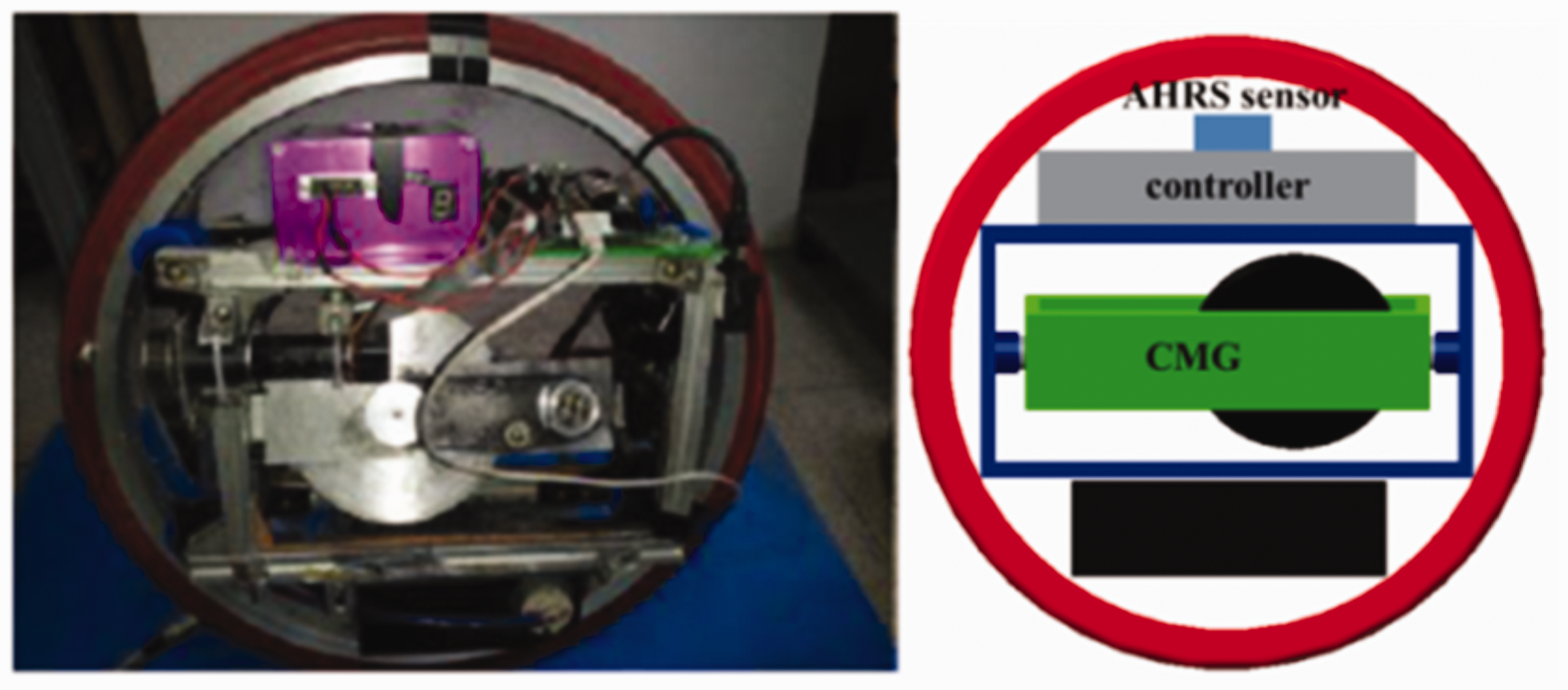
There are three motors inside the wheel, two motors for balancing control and one for driving control. As a main controller, a DSP TMS320F2812 is utilized to control CMG every 10 ms. The control panel transmits the flywheel speed command to the controller through the wireless communication ieee802.15.4. After parsing the command data, the controller sends the command set to the flywheel motor driver NT50A through RS-232C communication. The motor driver provides the power to the flywheel motor. The AHRS sensor has a 0.05° resolution and a 100 Hz bandwidth. The control hardware is shown in Figure 2.
Overall system structure.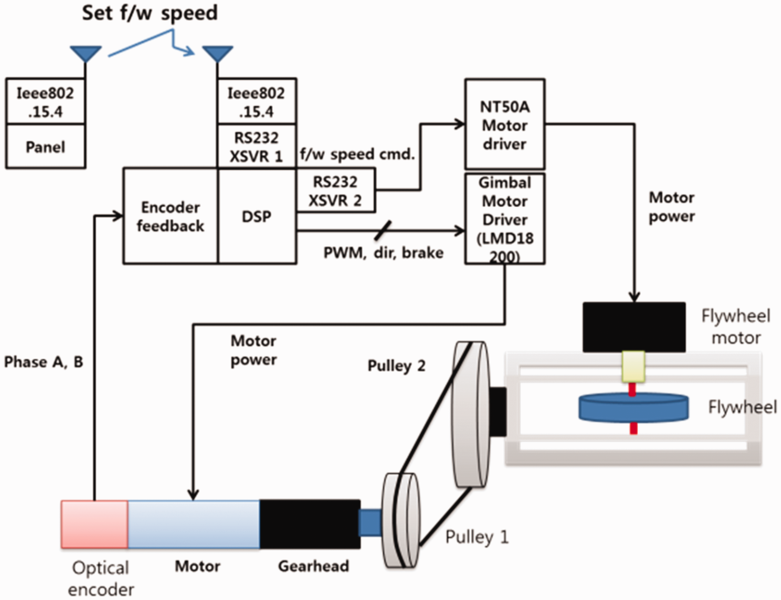
Balancing mechanism
The SWR is a self-balancing system that uses a gyroscopic effect induced by a combination of the angular momentum of a flywheel and the tilting rate of a gimbal system, as shown in Figure 3. The tilt motion of the flywheel actually controls the gyroscopic force in the yaw direction. By the reaction effect from the ground friction, the roll motion can be generated.
Balancing control mechanism.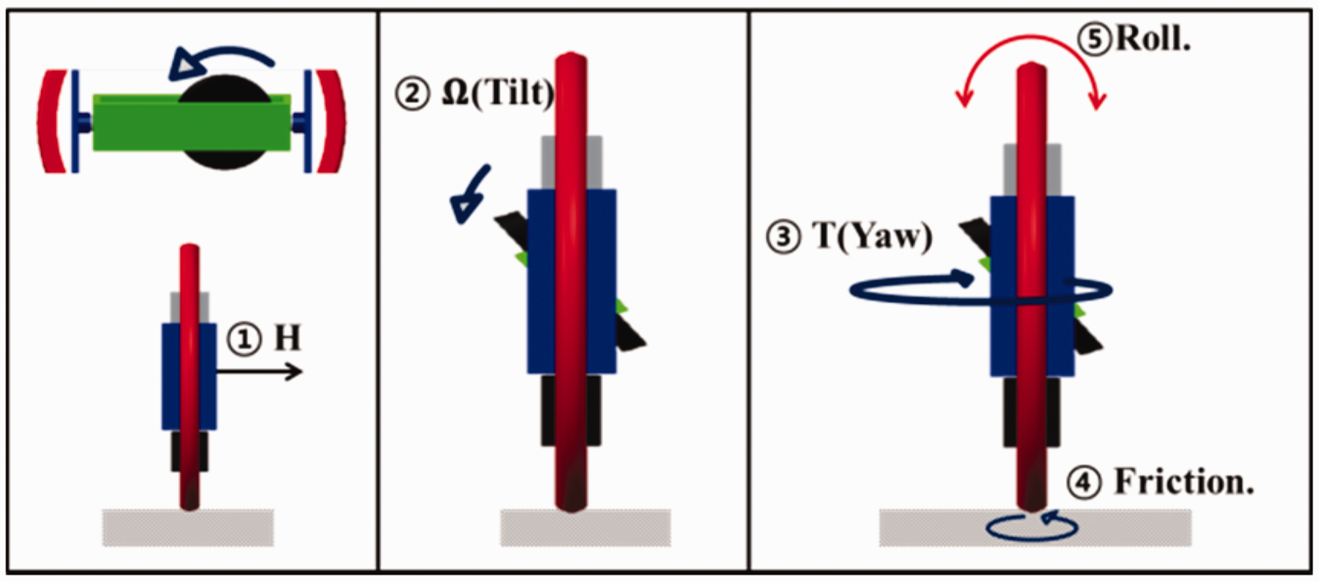
However, using an asymmetric flywheel structure, unexpected vibrations are easily generated. Although the flywheel is finely manufactured, misalignment with the actuator can cause such a vibrating problem. Therefore, the vibration of a rotating mass is a crucial point in the motion control.
In the given system, the transversal vibration of the flywheel can generate an unexpected tilt motion. A gyroscopic torque can be obtained by the cross product of two vectors as

The gyroscopic vibration generates the perturbation to the sensed signals. In the feedback control scheme of SWR, the clean measurement is strongly related with the balancing control performance. Although the passive isolation method must be considered in the installation step of the utilized sensor system, it is difficult to satisfy both the sensitivity and the cleanness of the sensor system. The balancing control performance requires sensitive feedback of measured signals as well as the cleanness in the signal. Therefore, investigating the characteristic of the gyroscopic vibration is a first step before applying an active control.
Detection of vibration
In the control of SWR, gyroscopic actuation and sensing process are a principle routine to achieve the balancing performance. For advanced and endurable balancing performance of the robot, sensitive but clean measurement of the attitude is indispensable. To achieve the sensitivity of the utilized sensor, the physical absorber such as passive isolator can be an obstacle in some aspects. Reversely, it is preferable to utilize a dense isolator for the clean measurement. In addition, the proper design of a passive isolator has difficulties due to the space limitation, manufacturing uncertainty, and an installation method. More difficulty of the only-passive isolator method comes in the notch-function design. Although a state-of-the-art technique for the passive isolator design is addressed in Ibrahim 31 and Kamesh et al., 32 the confirmation of the performance is not mentioned.
The vibrational source of the SWR system originates from the imbalanced flywheel. The speed of the flywheel is controlled as an open-loop manner in the system. Also, the flywheel actuator has no feedback sensor system such as an optical encoder. Only voltage commands are applied to vary the speed of the flywheel in the motor driver. Under this circumstance, direct measurement of the vibrational sources is difficult. In addition, the optimized sensing solution dealing with the gyroscopic sensing is unavailable.
Therefore, our novel idea is to use the same AHRS sensor for the detection of vibrations. Indeed, an AHRS sensor is already utilized for the measurement of a roll angle and a roll angular rate for lateral control of the SWR. The AHRS system consists of three gyro sensors, three accelerometers, and three magnetic sensors inside. The AHRS sensor is implemented by means of the gyroscopic principle. Therefore, it is appropriate for the AHRS sensor to detect gyroscopic vibrations.
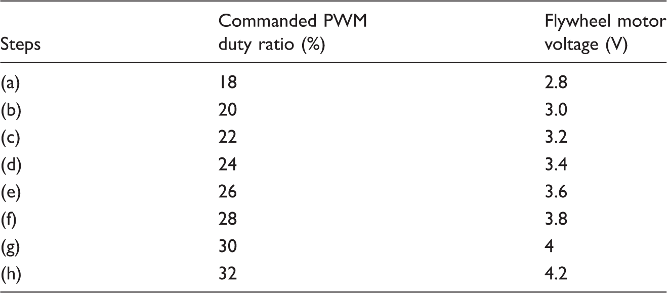
To detect the gyroscopic vibration, the experimental setup is described in Figure 4. The ground effect is removed, the panel is used for the speed change of the flywheel, and the data logger is used for logging the sensor data. Since the flywheel motor has no feedback sensor system such as an optical encoder, the flywheel is controlled as an open-loop manner. The speed of the flywheel can be changed by adjusting the steps of the panel. Flywheel motor voltages are tested by increments of 0.2 V and listed in Table 1.
Experimental setup. Flywheel motor voltage.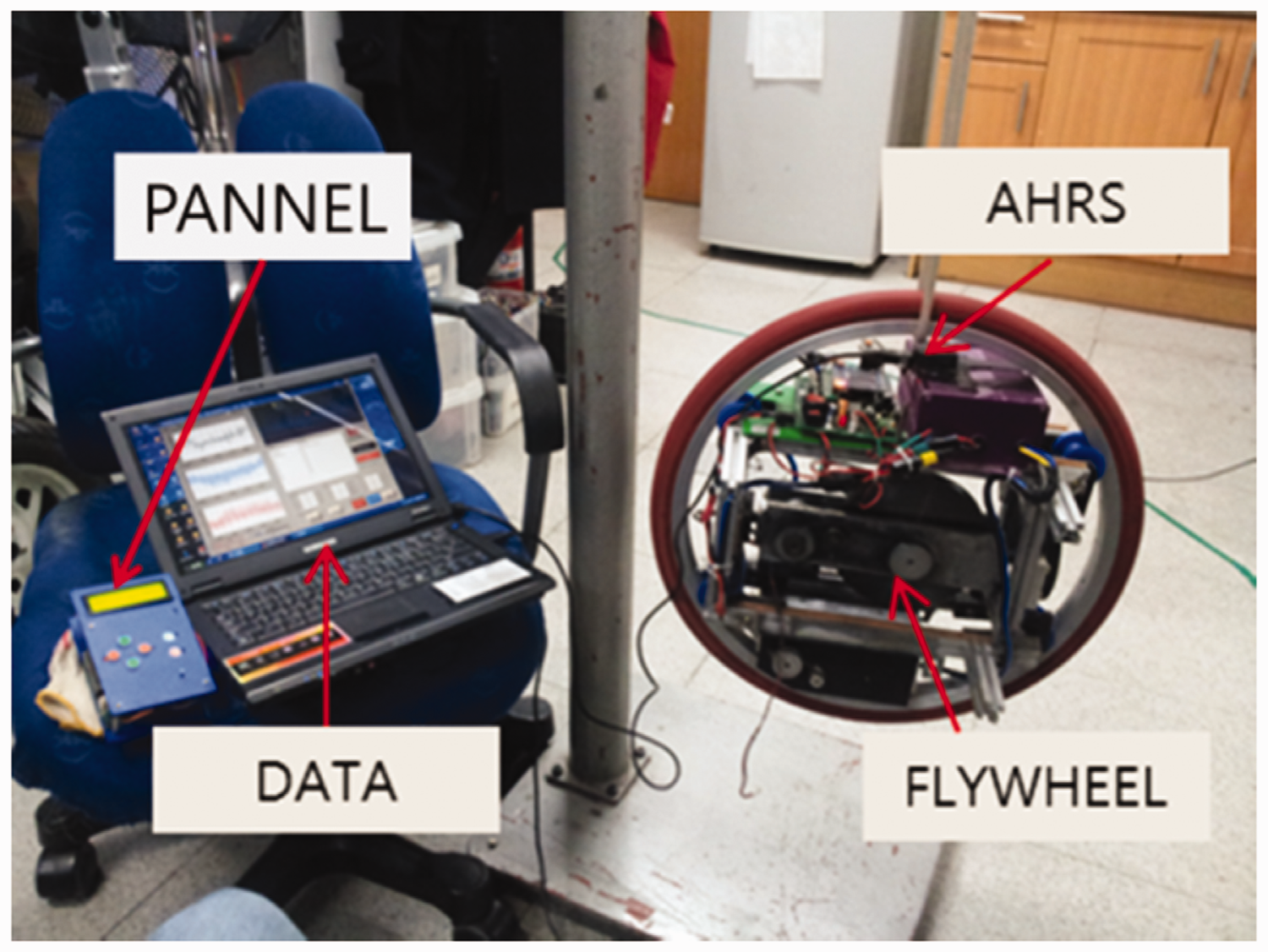
Yaw rate data are gathered with respect to different voltages and are described in Figure 5. The vibrational effects are observed in the yaw rate signals while both the position signals and the acceleration signals are not affected in the measurement. A total of eight steps of yaw rate data are collected, but the vibrational characteristics are hardly seen in the time domain of Figure 5.
Yaw rate data in the time-domain.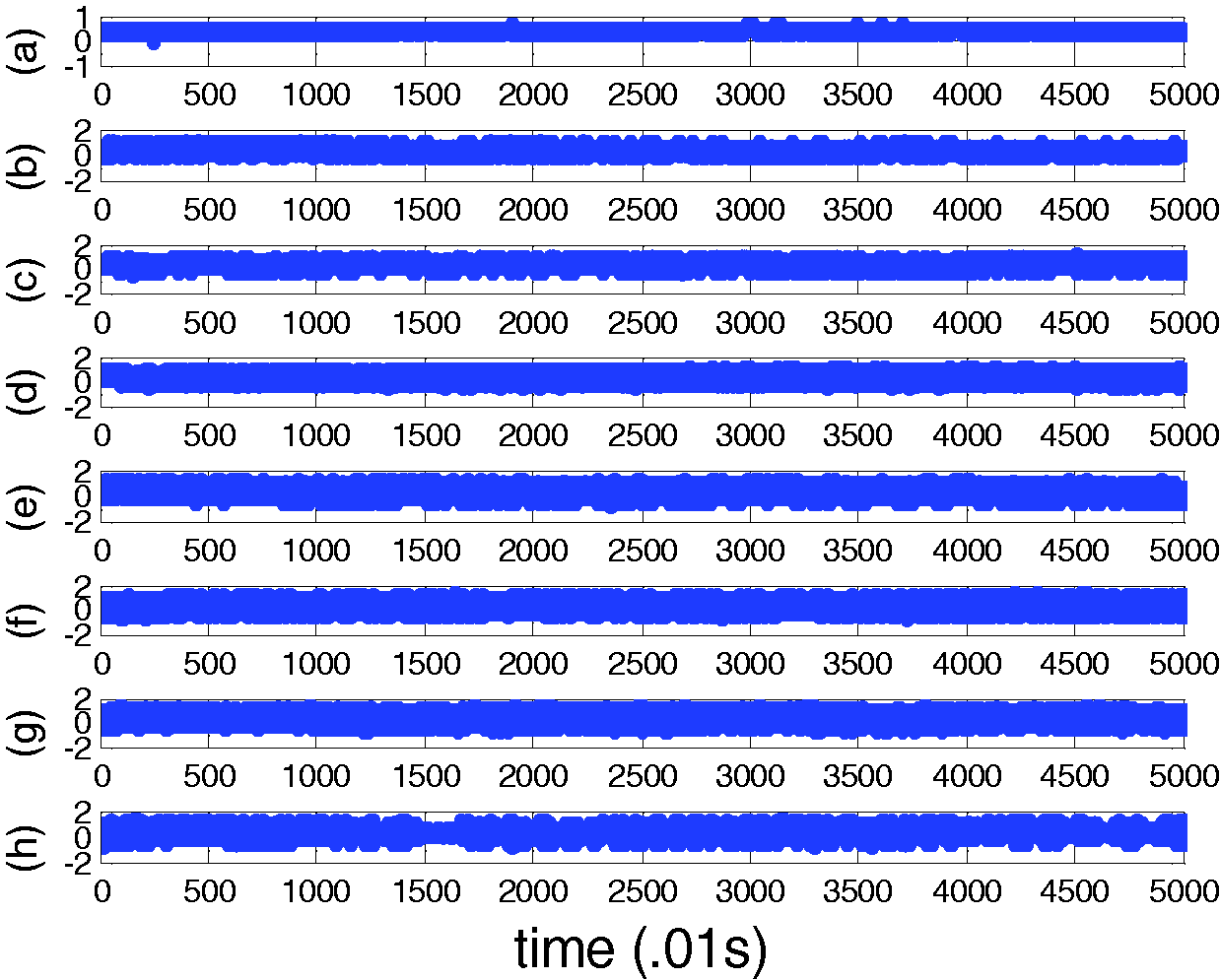
The frequency characteristics of gyroscopic vibrations of Figure 5 are investigated using the FFT (Fast Fourier Transform) and shown in Figure 6. The vibrational frequency peaks appear linearly shifted as the flywheel speeds are linearly increased.
Yaw rate in the frequency-domain.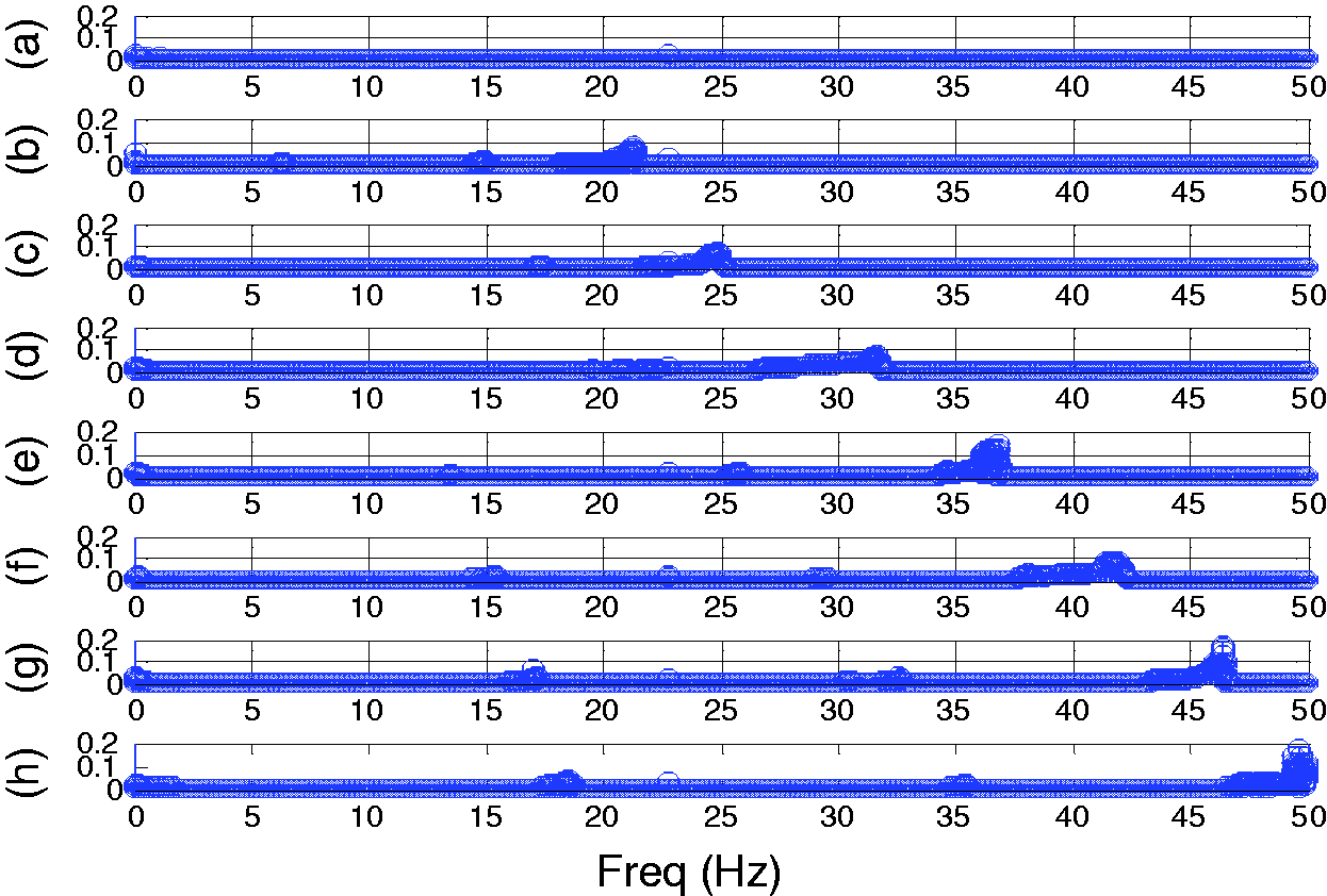
Therefore, there is a linearity between the rotational speed and the gyroscopic vibration. The results show that the gyroscopic vibration can be identified through the speed signals by the AHRS sensor system. In addition, the speed dependency of the gyroscopic vibrations is verified, and the direction of the vibration is clearly shown in the expected yaw motions.
Filter design
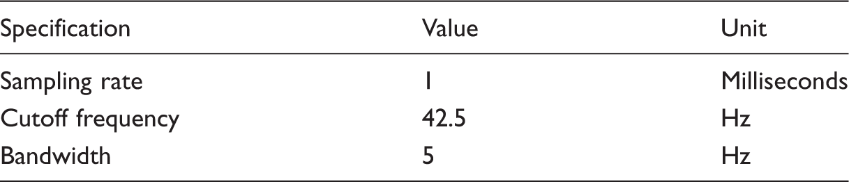
Filter design specifications.
The prototype of the notch filter can be shown as follows

The bilinear transform leads to the resultant filter equations as follows

Arranging equation (3) yields

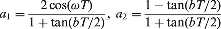
After the coefficients of equation (4) are calculated, the overall transfer function of the digital notch filter can be expressed as follows

The corresponding filter characteristics in the frequency domain are shown in Figure 7.
Notch filter characteristics.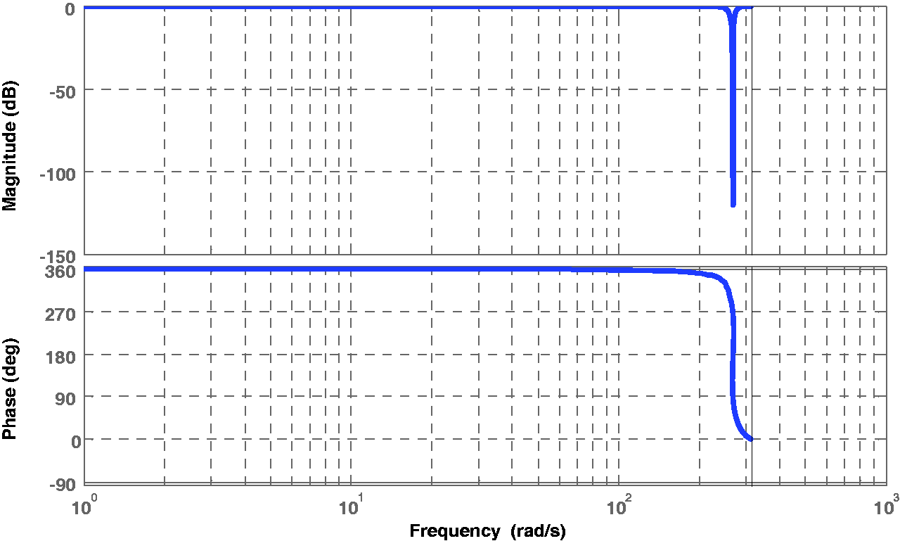
Control of the vibration
The next step is to suppress the vibration detected in the experiments. When the designed filter is applied, the yaw rate signals are investigated. Figure 8 shows the unfiltered signals and the filtered signals in the time-domain. We clearly see that the magnitude of filtered signals is small. In the time-domain, the mean values of the unfiltered signals and the filtered signals are the same values, 0.3420. However, the covariance of the unfiltered signals is 0.2917 and the covariance of the filtered signals is 0.873.
Notch filter effect in time-domain: (f) unfiltered data, (ff) the filtered data.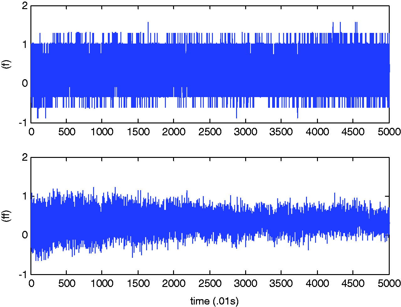
Figure 9 shows the unfiltered signals and the filtered signals in the frequency domain. It is clearer in the frequency domain that signals around 42.5 Hz appear to be large, as illustrated in Figure 9(f). Those signals are reduced after filtering, as shown in Figure 9(f). We clearly see that signals at 42.5 Hz are filtered out.
Notch filter effect in frequency-domain: (f) the unfiltered signal, (ff) the filtered signal.
In the power spectrum, the filtering power and the filtered power are compared in Figure 10. The unexpected vibration of −10 dB reduction has been achieved by the designed notch filter.
Power spectrum comparison.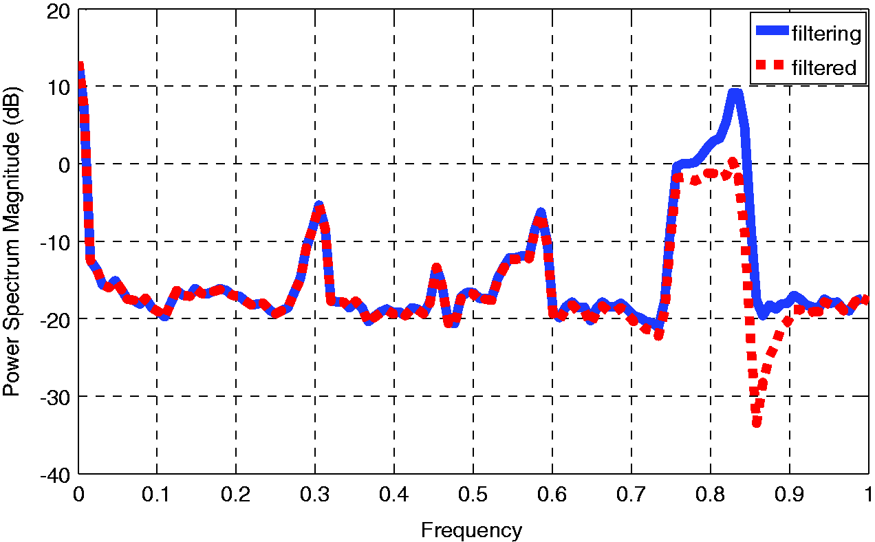
Experiment
For experimental verification, the designed notch filter is added to the control algorithm.
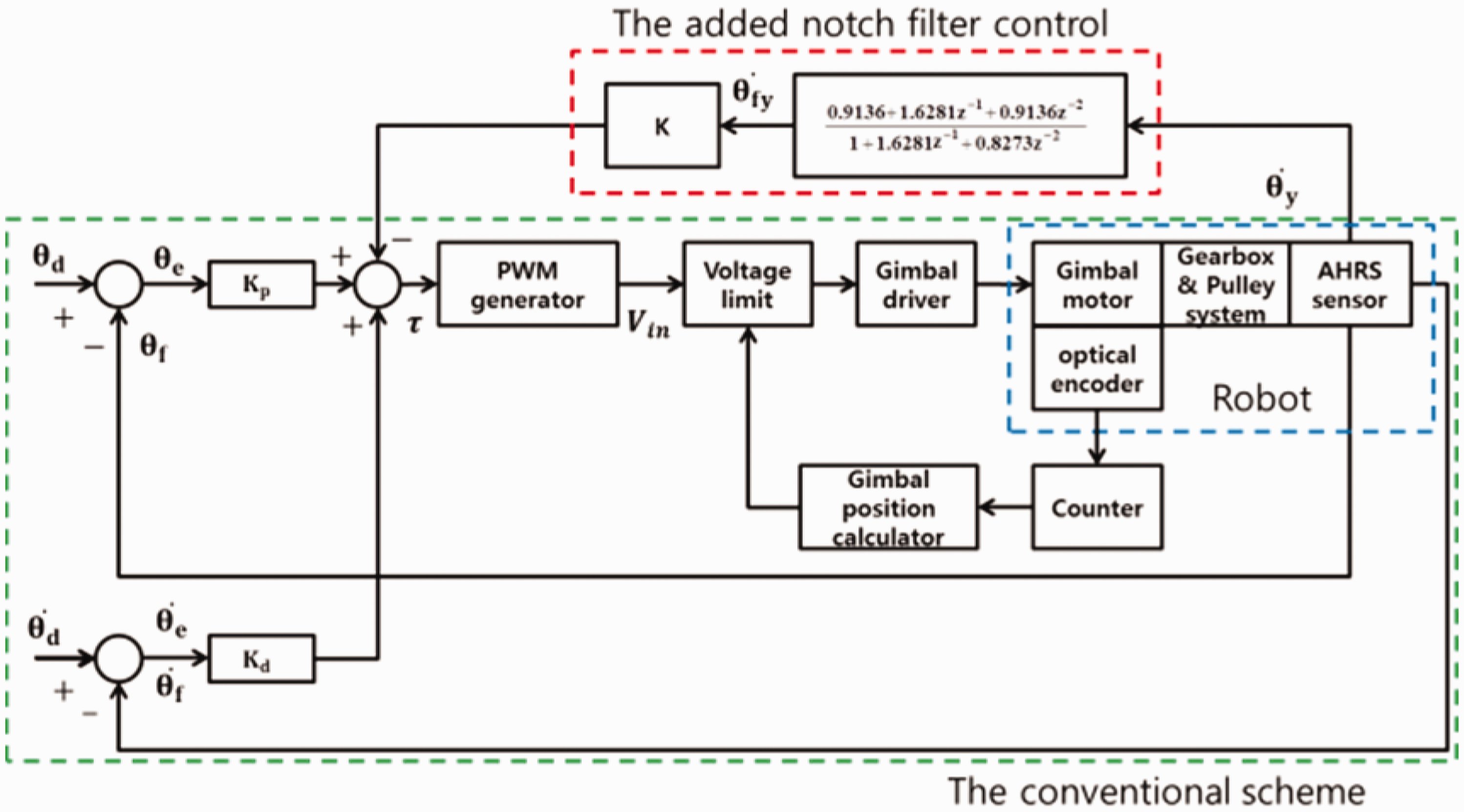
The overall control scheme is shown in Figure 11. The primary control is a PD control method along with the filtering technique. The PD control torque can be calculated as
The proposed control scheme.
The experimental setup is shown in Figure 12. The SWR is initially located on the reference line marked on the floor in order to distinguish the deviation due to the vibration.
Experimental setup (top view).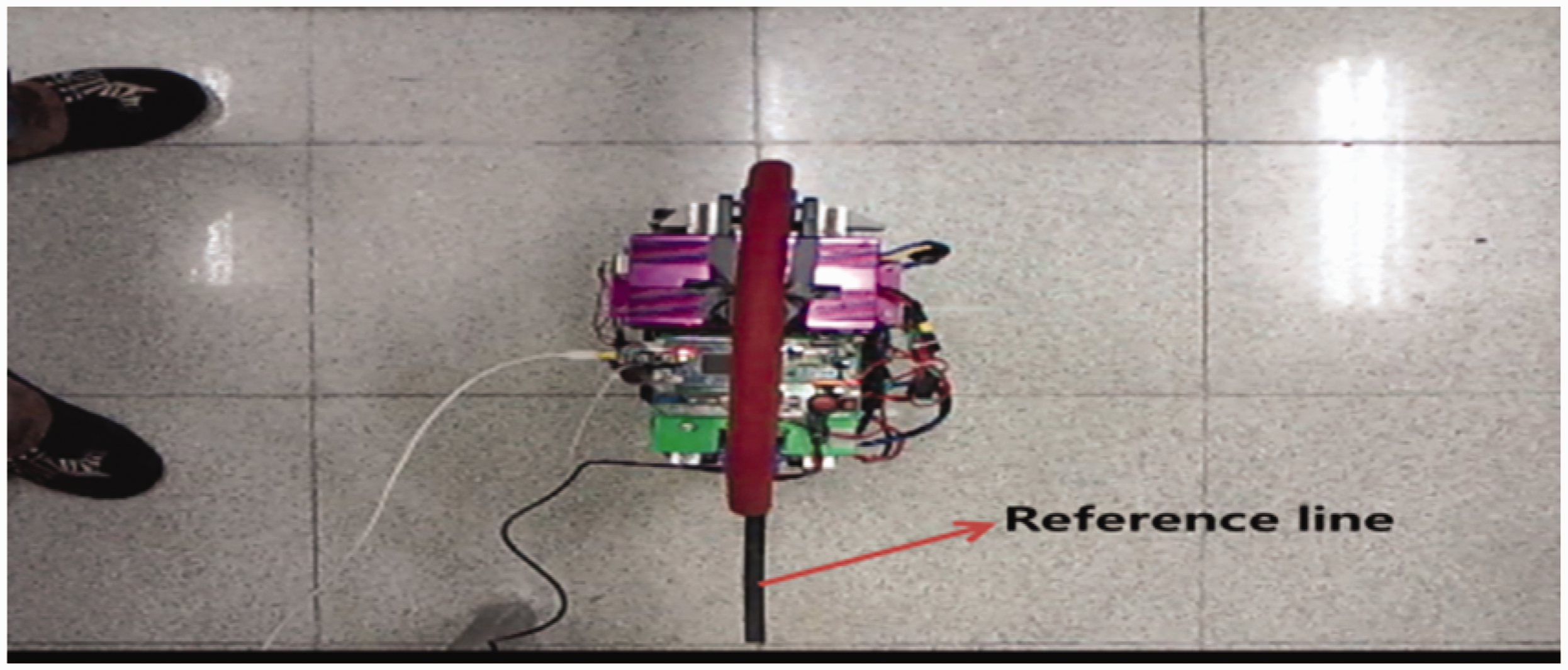
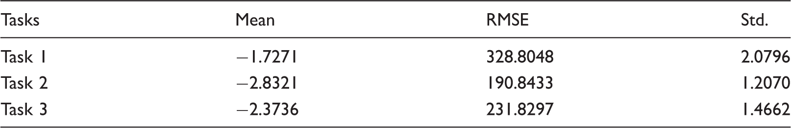
To evaluate the balancing control performances of the SWR system, 10 identical experiments are conducted. Among them, three successful results are plotted for 250 s in Figure 13. The mean, variance, and RMS error for the three cases are listed in Table 3. The deviation from the reference is about 5°, which means the oscillatory balancing response although the balancing control was successful.
PD-only control performances. PD control balancing performances.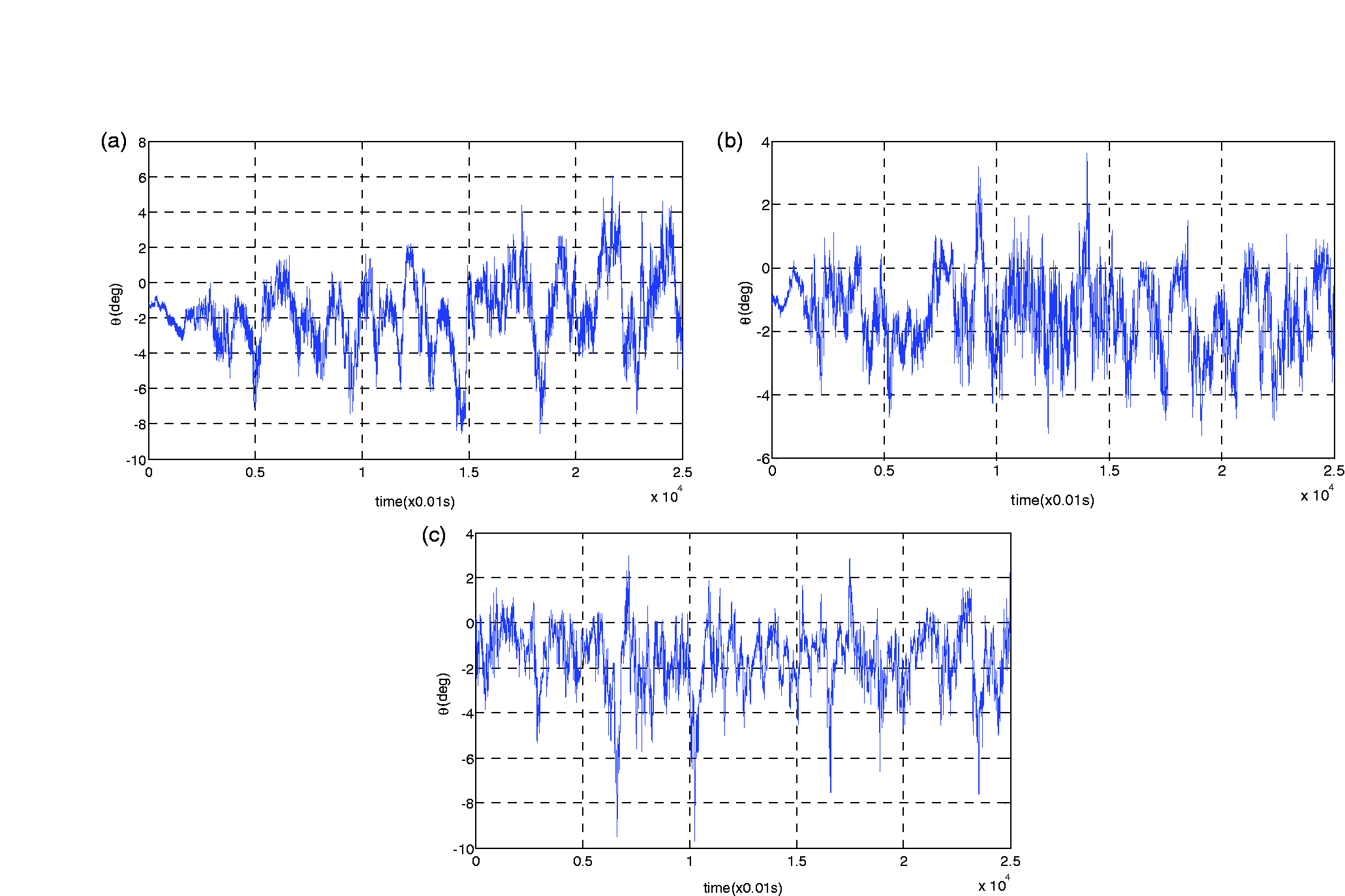
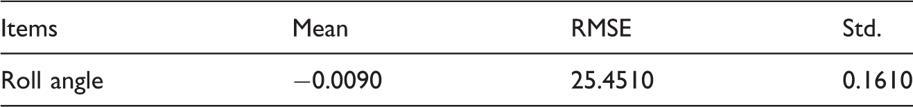
Next, we add the filtering technique to the controller and perform the same experiment. The balancing performance, displayed in Figure 14, shows a much smaller deviated error, namely 1°. It is clear that filtering the vibration improves the balancing performance of the SWR considerably. The corresponding captured video images are shown for 250 s in Figure 15.
Control performance with filter. Balancing control performance.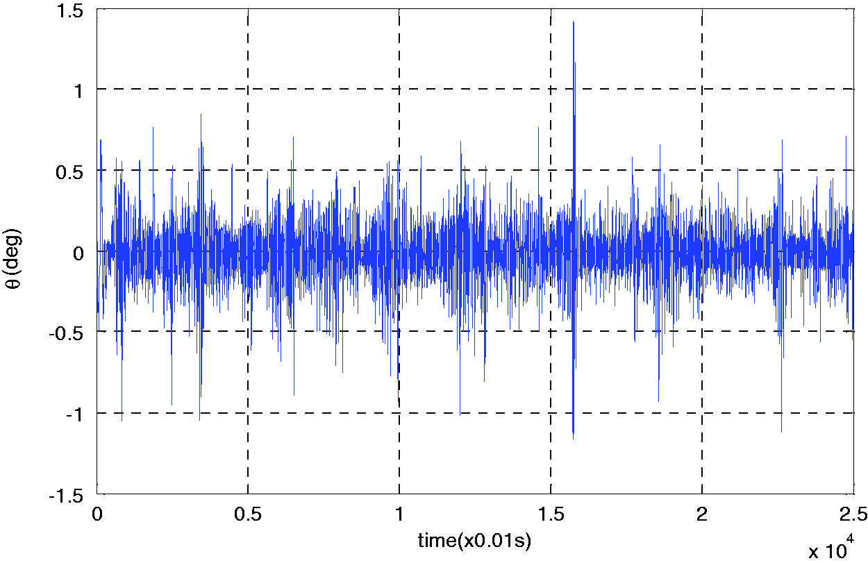

Balancing control performance.
Conclusion
The balancing control performance of the SWR depends upon the gyroscopic force induced from the fast rotating flywheel, which causes vibration. The gyroscopically induced vibration has been managed by identifying by an AHRS sensor and by filtering the vibration frequency by the notch filter. The vibration has been remarkably reduced and the balancing performance of the SWR has been improved. It is also confirmed that an AHRS sensor can be used as a measurement device as well as utilized for measuring the attitude of the system. Therefore, when typical sensors are unavailable, an AHRS sensor could be one optimal sensor for detecting vibration of the system.
Declaration of conflicting interests
The author(s) declared no potential conflicts of interest with respect to the research, authorship, and/or publication of this article.
Funding
The author(s) disclosed receipt of the following financial support for the research, authorship, and/or publication of this article: This research has been supported by the National Research Foundation of Korea under the contract of NRF-2014R1A2A1A11049503 and 2016R1A2B2012031)