
Abstract
Shock and vibration are a source of failures in harsh environments such as military, naval and aerospace applications; thus, the use of vibration isolators is extended. Cable isolators are known for their high-energy storage and dissipation properties making them suitable for shock isolation and low frequency vibration. Such isolators present nonlinear stiffness in different directions such as compression, roll and shear, as well as dry friction damping. Although their use is extended, the knowledge regarding their dynamic response under shock loading is very limited. This work presents an overview of the vibration and shock isolation performance of several cable isolators under axial loading. The main contribution of the paper is to investigate and discuss the shock response of the isolators when subjected to pulses of different durations, finding improved isolation performance when compared to an equivalent linear system. Furthermore, a mathematical model based on a Duffing oscillator is proposed as a first approximation, in order to reflect the nonlinear stiffness and predict the shock response, thus facilitating further design and selection of improved shock isolation systems.
Introduction
Transient mechanical vibrations are a common source of undesirable effects such as wear, fatigue, noise, etc., and the use of vibration isolation is generalized to mitigate these effects. This is particularly important in extremely harsh environments such as military, naval, and aerospace applications, 1 i.e. for the protection of avionics components and the isolation from vibration produced by engines and propulsion systems in unmanned air vehicles (UAVs). 2 Wire rope also known as cable isolators are commonly used in these examples due to their high energy storage and dissipation properties. However, most of the isolation designs based on wire ropes are empirical or based in classic isolation theory, which does not reflect the nonlinear properties typically observed in these isolators. Moreover, there is not a complete study describing analytically and experimentally the dynamic behaviour for different dynamic loads.
This work presents advances on results of different dynamic and static tests performed in several commercially available wire rope isolator samples. The objective is to present actual data that shows the improved shock isolation properties due to the nonlinear stiffness and damping, discussing the behaviour, advantages and issues related to these isolators. First, a comprehensive literature review is presented, addressing the most important findings related to wire rope springs and nonlinear shock isolators. The next section describes the isolator samples studied, and the experimental procedures are considered. The subsequent follows the measured results of the static-force deflection and stiffness properties, and then the vibration and shock response transmission and isolation is estimated. Then the results are discussed. Furthermore, a mathematical model using a cubic stiffness approach, i.e. duffing isolator is proposed in the next section, in order to predict the response of such isolators. Finally, the paper concludes with a summary and suggestions for further work, where the development of a mathematical model will enable future applications in isolation technology and vibration and noise control, particularly aerospace applications, i.e. landing gears, unmanned aircraft systems, and avionics.
Background
Transient vibration is a short but impulsive vibration type, also known as shock or impact.
3
Shock response is typically characterized using parameters such as relative and absolute displacement, related to the available space or clearance, and the maximum acceleration, which is an indicator of the forces transmitted. The maximax response is defined as the maximum response to a particular shock pulse at any time. The value of this response depends mainly upon the duration and shape of the shock. Several ideal pulses can be considered such as half sine, rectangular, trapezoidal, etc., and more complex pulses can be used as well. Normally the duration of the pulse τ is compared to the natural period of the system T in order to evaluate the maximax response. When the pulse is of short duration, i.e. less than half the natural period of the system, the response is smaller in magnitude than the excitation. For longer duration inputs, approximately similar to the natural period of the system, the maximum response is larger than the amplitude of the input. Finally, for pulses of much longer duration compared to the natural period, the shock is applied relatively very slowly and the response becomes quasi-static. This shock response is summarized in Figure 1(a), which presents a single degree-of-freedom (SDOF) system subjected to a half sine pulse acceleration (a) Shock response spectra (SRS) of an SDOF system subjected to a half sine pulse acceleration applied at the base presented as a function of the period ratio 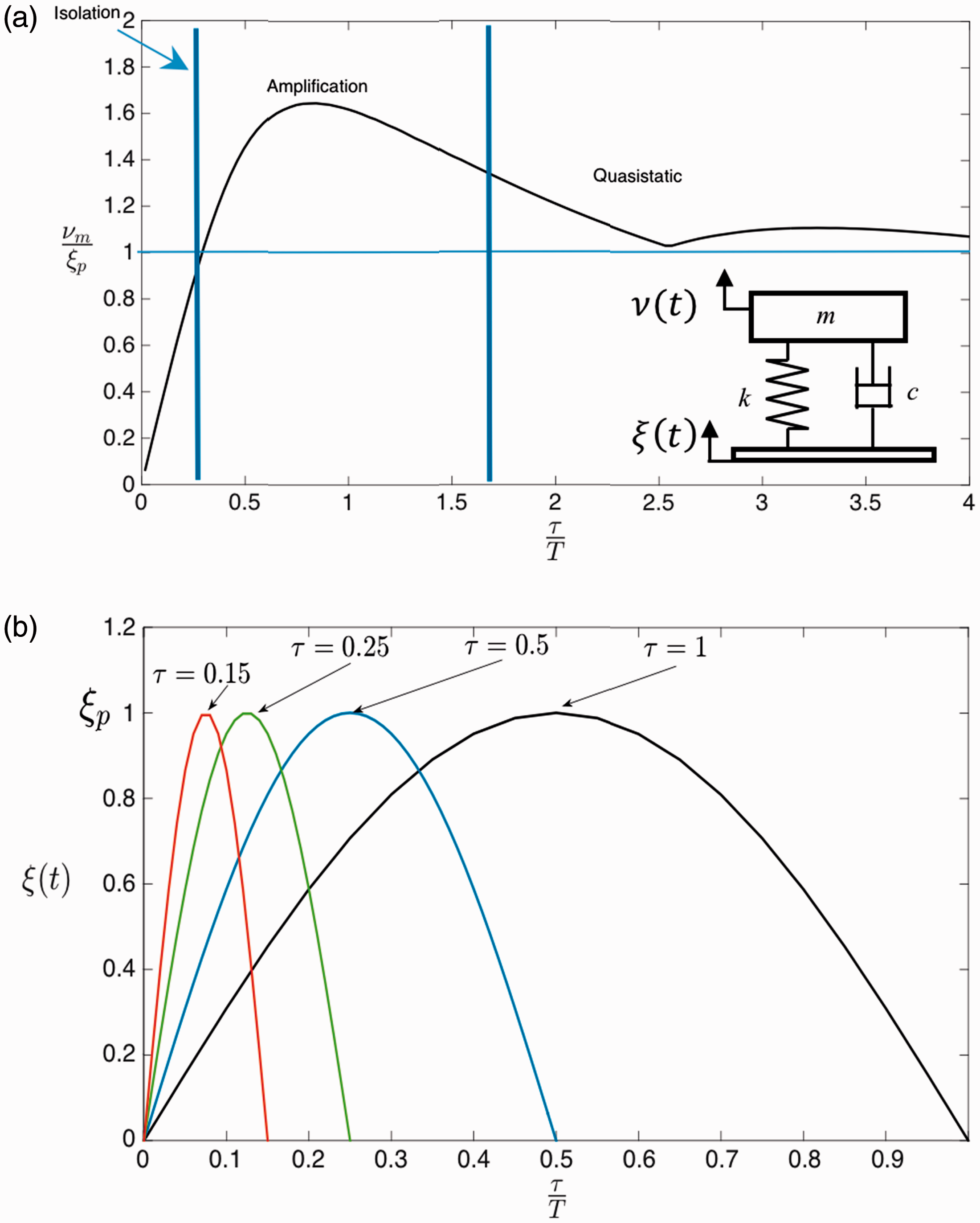
In order to achieve shock isolation, it is required to have flexible supports resulting in large relative displacements and static displacements resulting in a low natural frequency for the supported mass. A common type of isolator used for vibration and shock isolation are the wire rope springs, also known as cable isolators, the models used in this investigation, are presented in Figure 2, which are regarded as highly effective for extreme conditions found in military, naval and aerospace applications.
(a) Typical cross section of a 7 × 7 (seven ropes with seven wires each). (b) Details of the cable and its construction. (c) Commercial samples of wire rope isolators used in the study with leaf configuration (Models 1 and 2) and helical configuration (Models 3 and 4).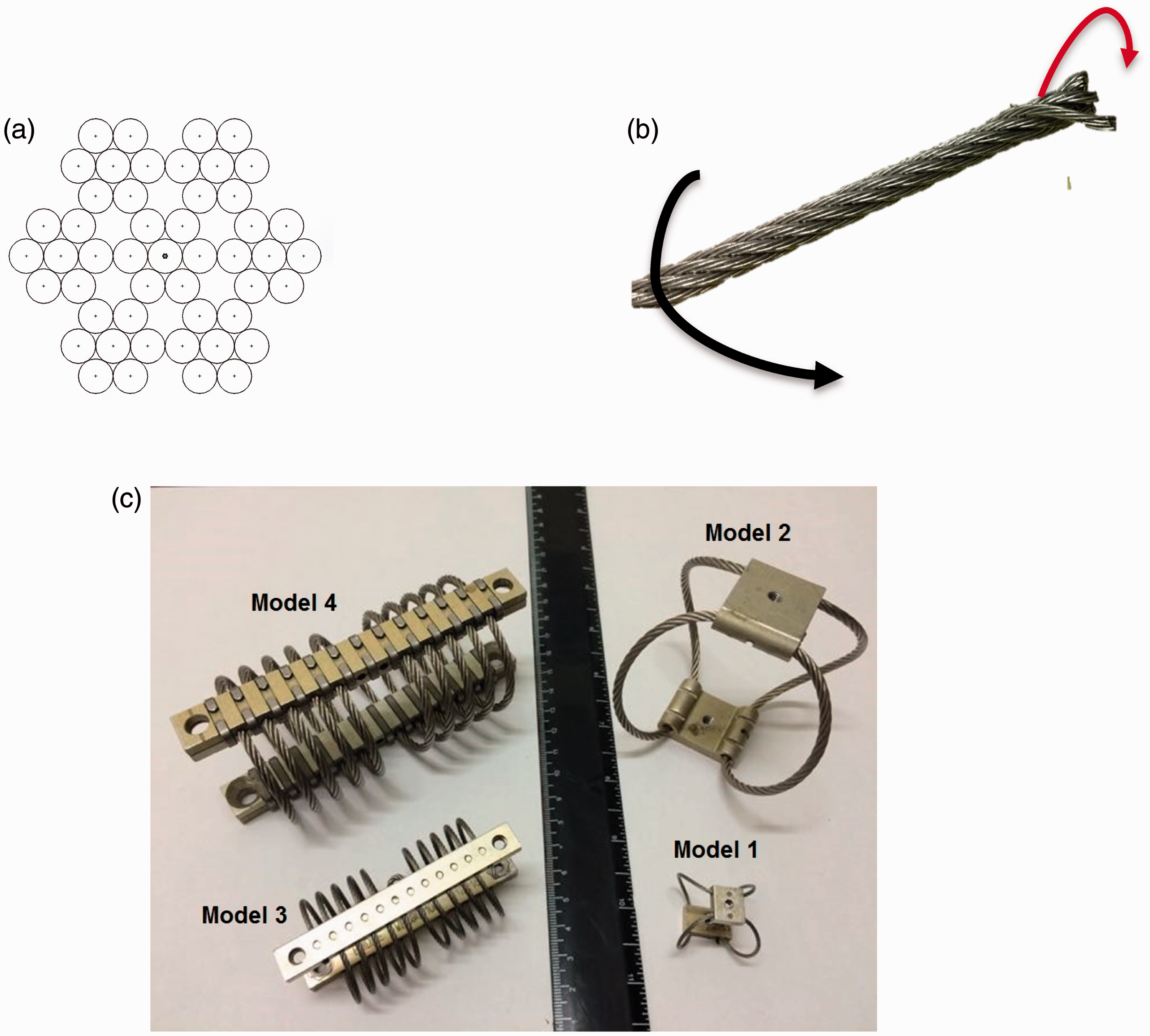
Cable isolators are build using a series of steel strands twisted around a core strand, and the resulting wire rope is arranged in a leaf (i.e. models 1 and 2 from Figure 2(c)) or helical (i.e. models 3 and 4 from Figure 2(c)) fashion. They have a great capability for energy dissipation due to the friction created between the wire strands as the cable twists when the isolator is loaded and unloaded. An advantage of these isolators is that they can work in tension-compression, shear and torsion scenarios. Apart from the nonlinear Coulomb damping observed in these isolators, they also present nonlinear stiffness characteristics.
Cutchins et al. 4 published studies on nonlinear stiffness and damping, in which an analytical model for the description of the hysteresis loop, that is common in systems with nonlinear stiffness, was derived. This study focused on the wire springs, the authors noted that the spring wire strands tend to separate when compressing, while when tensioned a greater number of contact points exist and the resistance to relative motion is increased, forcing the force displacement function to behave differently in tension than in compression. Demetriades et al. 5 also investigated the response of cable isolators under earthquakes excitation and derived an analytical model that was calibrated using experimental results. Popp 6 performed a theoretical investigation, citing relevant studies to the discontinuous nature of both phenomena: impact and friction, highlighting everyday examples where they are seen and was considered the importance of their study. Leenen 7 and Schwanen 8 presented the characterization of dry friction springs using a modified model of Bouc-Wen which is widely used for the description of hysteretic systems, considered as a semi-physical mathematical model. Guzman-Nieto et al. 9 assessed the experimental measurement of damping in wire rope isolators, finding that there is a maximum in the energy dissipation at a certain load, i.e. displacement of the isolator, and that for higher loads, the energy dissipation decreases. Ikmal 10 presented an active impact isolation system, incorporating a mathematical model with Coulomb’s damping, demonstrating theoretically and experimentally that although the friction greatly reduces the maximum displacement, a sharp transition is observed in the instantaneous change of acceleration, whenever the frictional force changes direction. Moreover, it is important to mention the recent increased interest in variable and nonlinear stiffness strategies for control and isolation of shock produced vibration, demonstrating the feasibility and isolation performance of low dynamic nonlinear stiffness for high-level excitations.11–13 Apart from the study of Guzman-Nieto et al., 9 to the knowledge of the authors, there is no published study dealing with the shock response of wire rope isolators.
Experimental development
For this study, four samples of wire rope isolators were considered, from two different manufacturers, based on two typical configurations as presented in Figure 2(c). The choice of these samples was based on availability, because these are two of the most common configurations commercially found. Moreover, the models represent similar configurations in different load capacities. Although these isolators are able to isolate in axial, roll and shear motion, this study is limited to axial (tension-compression) load due to technical restrictions of the experimental facilities where the testing was performed.
The experimental procedure was divided in three parts. First of all, a static test was conducted. In this test, a slowly increasing force was applied to the isolators in order to register the deflection observed as a function of the force applied, and obtain the static stiffness characteristics of each isolator. The experiments were carried out using a universal testing machine Shimadzu model AGS-X 10. The schematics of the procedure are presented in Figure 3(a). For the dynamic tests, as depicted in Figure 3(c), the isolators (4) were attached to an electrodynamic shaker LDS model V721 (3). The isolators were exposed to a broadband random excitation applied from the base, measuring input and output acceleration with piezoelectric accelerometers (5). A computer (1)and a shaker control system (2) were used to control the shape, duration, and amplitude of the excitation, while a different computer (7) and a dynamic signal analyser (6) were used to capture the time data. Vibration isolation properties were calculated and presented as transmissibility curves in the frequency range of 5 Hz to 1500 Hz. This frequency range was selected in order to capture the fundamental natural frequency of the system, assuming an SDOF approximation. The experiment was conducted first without any load on the isolator, then a reference mass was attached at the top of the isolators. The value of the added masses was 0.059 kg, 0.342 kg, 0.922 kg, 1.554 kg for isolators 1, 2, 3, and 4 respectively, in order to exert an initial static deflection and be able to provide vibration isolation. The third set of tests involved the measurement of response to shock excitation. The setup used was the same of the transmissibility tests as explained before. However, in this case, the excitation was a half sine acceleration pulse applied at the base of the shaker, for different durations of 10 ms to 40 ms with 5 ms intervals. The amplitude of the pulses was 2 g and was kept constant for all the pulses. As before, input and response accelerometers were used to register the time response, then the SRS were computed for all the pulse durations analysed. Shock response was measured with mass loading according to each isolator load capabilities. Actual pictures of the experiments can be seen in Figure 3(b) and (d).
Experimental setup (a) schematic diagram of static experiments (b) actual setup of an isolator; (c) schematic diagram of dynamic experiments and (d) actual setup for transmissibility and shock experiments.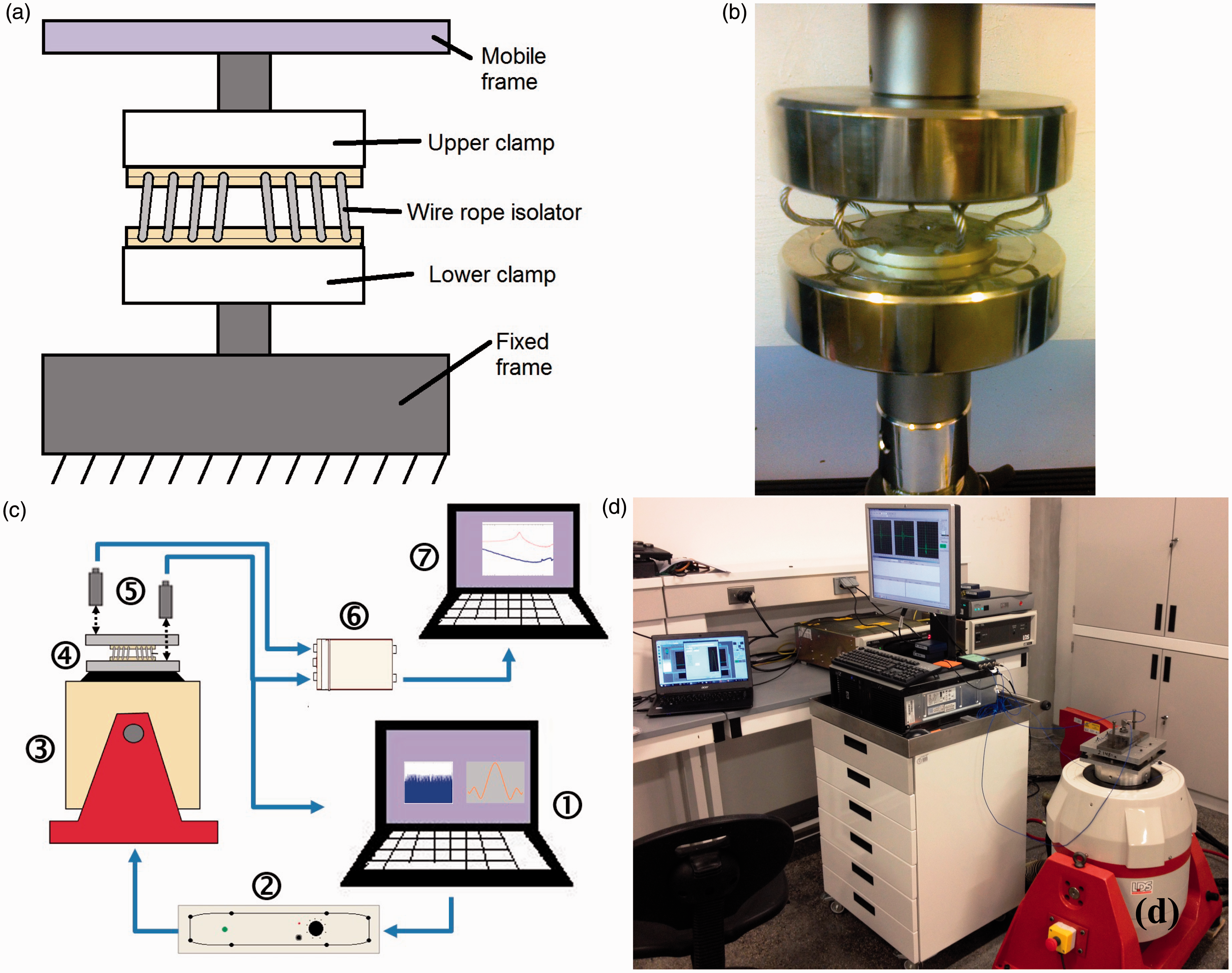
Results
This section presents and discusses the results of the experimental testing according to the different cases considered. The experimental measurements were analyzed using post processing software in order to fit the data and obtain damping and natural frequency for the samples.
Static tests
To determine the static properties of the isolators from the compression test, of each wire rope model, force–displacement curves were obtained and depicted in Figure 4. The isolators were tested to their maximum load capacity, thus obtaining the maximum possible displacement on each one. A nonlinear effect in the force–displacement curves and how the isolators become stiffer for large displacements can be observed. Around the middle region of the curves, the instantaneous slope is very small, and this effect is more prominent in the isolator Model 3. This stiffness behaviour has been referenced by previous studies as quasi static stiffness, meaning a low dynamic stiffness about a prescribed equilibrium point, but higher static stiffness, which might be desirable for better vibration isolation properties.
14
As some previous studies suggest, this behaviour can be well represented by a Duffing isolator, i.e. cubic stiffness term. Hence, a cubic fit was calculated and presented as an additional curve given by the continuous curve.
Force–displacement plot for wire ropes. Horizontal axis gives displacement in meters, and vertical axis represents force in Newton. (a) Model 1, (b) Model 2, (c) Model 3, and (d) Model 4.
Using the equations from the cubic curve fit, the force–displacement relationship was derived with respect to the displacement to obtain an analytical curve describing the behaviour of the stiffness for each model, as shown in Figure 5. As explained before, there is a minimum in the stiffness curve, which represents the displacement range for which the dynamic stiffness is low, which is desirable for the improved vibration isolation. Thus, this can be stated as an optimum load value for the isolators.
Stiffness plot for each point of displacement on wire ropes springs. Horizontal axis represents displacement (m), and vertical axis stiffness (N/m). (a) Model 1, (b) Model 2, (c) Model 3 and (d) Model 4.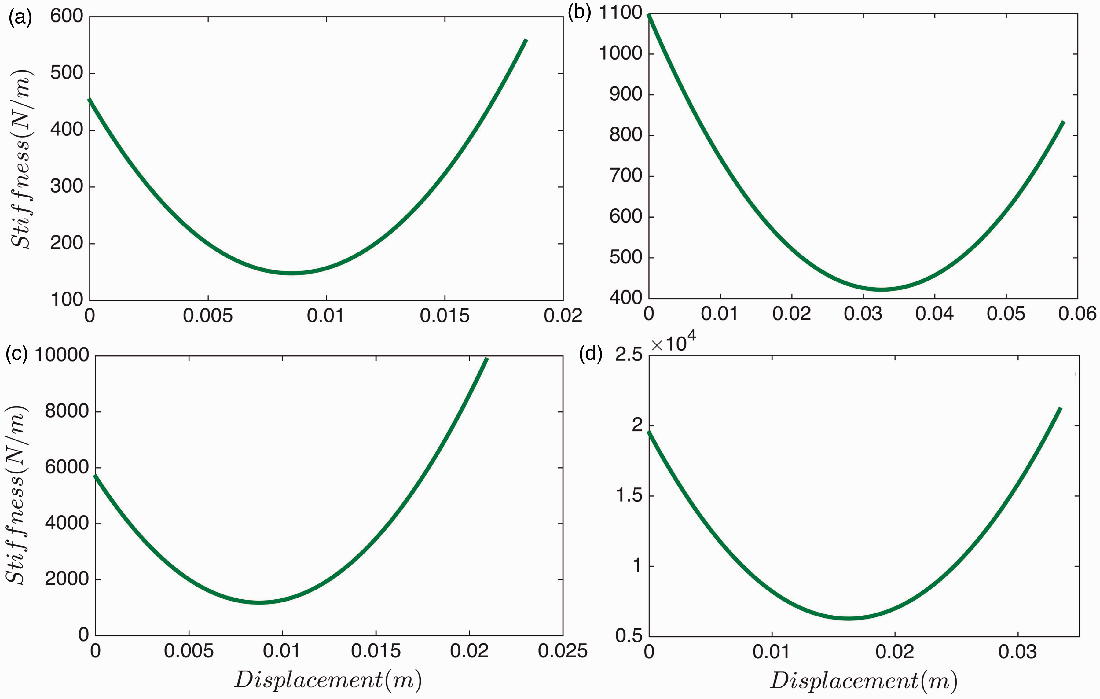
Frequency response tests
The results of the transmissibility curves are presented in Figure 6 for each model. Continuous (blue) line represents the isolator with mass loading, while the dotted curves (red) depict the isolator without mass. Without mass loading, the isolators present a high fundamental natural frequency with relatively low damping, as there is no initial deformation on the isolator. From the vibration isolation theory, a low natural frequency system presents better isolation, which can be expressed by the initial static deflection on the isolator.
15
However, when the isolators are loaded, the natural frequency decreases, allowing enhanced isolation for a wider frequency range. Moreover, the damping is considerably increased as well. The values of natural frequency and equivalent viscous damping ratio were calculated using an SDOF curve fitting procedure in a specialized modal analysis commercial software. These results are summarized in Table 1 for the fundamental frequency of the isolation system.
Plot of the magnitude of the vibration transmission ratio for the wire rope isolators considered. Vertical axis represents transmissibility magnitude as response x divided by excitation y, and horizontal axis represents frequency in Hz. (a) Model 1, (b) Model 2, (c) Model 3 and (d) Model 4. ( Fundamental natural frequency and damping for each wire rope spring system. loaded,  unloaded).
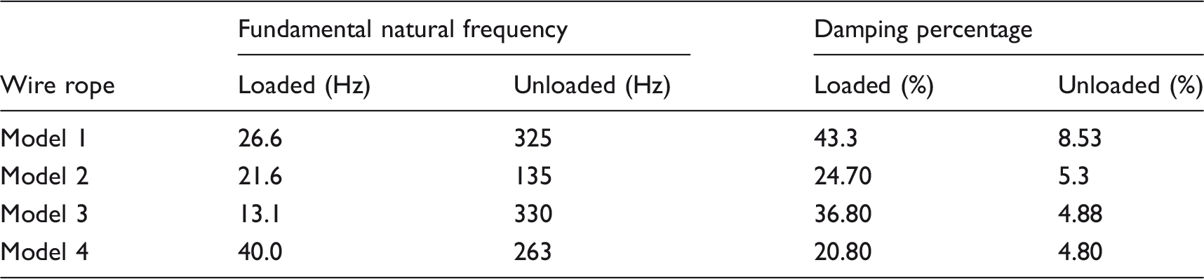
Shock response tests
The time responses for the four samples are presented in Figure 7. Each curve represents the response to a half sine shock of different duration, as stated previously. However, in this plot, only pulse durations of 15, 20, 30 and 40 ms are presented for the sake of simplicity and to facilitate the understanding of the plot. Vertical axis represents response in g and horizontal axis time in seconds. It is important to note the highly nonlinear behaviour in the curves, i.e. the response is non sinusoidal, which is more remarkable as the pulse duration increases. As stated previously, the response increases as the pulse duration increases, which can be observed in Figure 7 for the cases presented. As a result, the nonlinear effect is more important for the longer pulses. Additionally, isolator model 3 is the one that presents the highest nonlinearity in its force deflection plot, resulting in a high nonlinear oscillatory response, as depicted by Figure 7(c). However, in order to compare the actual shock isolation properties, it is more useful to present the information from the time histories in a single plot. Then, the response for all the pulses studied can be presented in a condensed and concise format. The SRS plots for each isolator are presented in Figure 8. In order to obtain these plots, the value of absolute maximum response to each shock duration considered was computed from the time history, and then normalized with respect to the maximum pulse amplitude, i.e. 2 g. The normalized values are plotted as a function of its particular shock duration to natural period ratio. The resulting plot is called SRS.
3
Figure 8 gives the normalized response, as a function of the effective duration of the pulse, i.e. 10 ms to 40 ms with 5 ms intervals, divided by the equivalent, or apparent natural period of the system, calculated from the equivalent natural frequencies measured and presented in Table 1. The shock response, of the isolator samples, is represented in Figure 8. For comparison reference, the shock response of the equivalent viscously damped linear systems is included. In this case, the equivalent viscous damping ratio corresponding to each isolator as given in Table 1 is considered. The lines included in Figure 8 represent the shock response of the linear systems.
Shock response for the wire rope isolators considered under a 2 g half sine pulse excitation for different durations of the pulse. Vertical axis represents absolute acceleration response in g, horizontal axis gives the time in seconds. The isolators considered are: (a) Model 1, (b) Model 2, (c) Model 3, (d) Model 4 ( Shock response spectra for the wire rope isolators considered under a 2 g half sine pulse excitation. Vertical axis represents maximum shock response divided by maximum input amplitude, horizontal axis gives the duration of the pulse divided by the apparent natural period of the system (▪ Model 1, 


 Model 2,
  Model 3,
  Model 4,
  linear undamped,
  %ζ = 20.8,
  %ζ = 24.7,
  %ζ = 36.8,
  %ζ = 43.3).
Discussion of the experimental results
The nonlinear nature of the stiffness of wire rope isolators is clearly revealed in Figures 4 and 5, where the plots show the typical behaviour of quasi-zero stiffness systems, also called tangential stiffness. These systems exhibit a particular static equilibrium point around which the stiffness is very low. As the displacement exerted in the spring increases so does the stiffness, showing a hardening behaviour. A cubic fit confirms this behaviour, which has been suggested previously by several studies. 14 The actual stiffness plot presented in Figure 5 represents the immediate, or tangential stiffness as a function of the displacement demonstrating the lower value of stiffness, thus an optimal loading setting can be established for the isolators studied. In practice, one would want to establish an equilibrium point around the minimum stiffness value, the required load to attain this point is hence referred as the optimum load.
Figure 6 shows the effect of mass loading on the isolators transmissibility. Although it is well known that increasing the mass improves vibration isolation by reducing the natural frequency, in this case not only the natural frequency is reduced, but also the damping is greatly increased. Previous studies 9 have demonstrated that the cable isolators require certain preload to effectively dissipate energy, and when unloaded their energy dissipation is very low. As presented in Table 1, damping values vary from 20% to 40% for the samples considered, while damping is about 5% when unloaded, which can be considered lightly damped, with the exception of isolator model 1, which has a damping of 8.5%. It is important to note that due to the restrictions in the testing facilities, the isolators neither could be tested at their nominal nor at their optimum load characteristics, due to the stability issues when loading a single isolator. As damping increases when the value of initial deformation on the spring increases, demonstrated in Guzman-Nieto et al., 9 it is expected that at optimum loading, damping will also increase. This can be explained considering that due to the nonlinear behaviour, cable isolators have a correlation between the maximum forces or maximum static load that supports and the displacement of the spring. Indeed, if the exciting force or load applied is smaller than the frictional force acting parallel to the contact surface then there is no friction between the wire strands of the spring, and damping tends to be small. It is also important to note that at higher frequencies, well, above the fundamental natural frequency, several resonances are observed possibly due to the wave effects on the isolators.
Regarding the shock response, in general terms, shock isolation is better when compared to an equivalent mass spring system. However, this is not a direct comparison, since it has been demonstrated that wire rope isolator exhibits important nonlinearities. It is important to note that for the isolator model 3, the actual shock response was higher when compared to the linear reference. As this was the stiffer isolator studied and considering that it could not be loaded with an optimum value of mass, there was not enough static deformation to provide isolation. However, it is expected that with proper load, the shock isolation characteristics will improve. Furthermore, it can be observed that significant improvement in shock isolation was observed during the amplification region of the shock response, which can be attributed to the low dynamic stiffness and high damping in the isolators.
Proposed mathematical model for shock response
A first approach for the mathematical modelling of the shock response of a wire rope isolator is proposed in this section. This model is based on the Duffing oscillator, which has been recently studied in its vibration isolation properties.16,17 This model is characterized by a cubic elastic force component, which can be hardening or softening. Isolators based on this model exhibit a low dynamic stiffness around a particular equilibrium position, and a high static stiffness otherwise, thus presenting improved isolation properties. The general form of the Duffing equation is
Plots of the cubic stiffness model (
When the isolation system modelled as a single degree of freedom, model is under a transient excitation in the form of a symmetric pulse, i.e. a half sine pulse, the equation of motion can be expressed as

In this case, the excitation is given by an acceleration pulse of amplitude ξp applied to the base of the isolator. The response is studied as a piecewise problem, i.e. the forced part from t = 0 up to the duration τ of the pulse, and then the residual free vibration era.
For this study, the elastic force components were obtained from the experimental static tests. The equilibrium position was set to the deflection giving the lowest stiffness point (as in Figure 4) which is under the recommended deflection for the isolators studied. In this case, the experimental data were centred about the equilibrium position, and it was normalised with respect to the maximum force and displacement recorded, in order to have a nondimensional plot as a result. Then, a linear least squares cubic fit was performed to obtain the constants of the stiffness force for the isolators, as presented in Table 2, and depicted graphically for the four isolators in Figure 10. The goodness of the fit was evaluated with the adjusted determination coefficient R2.
Force–displacement curves resulting from the cubic curve fit, considering scaled and centred data. Vertical axis represents normalised force, and horizontal axis normalised displacement. (– Model 1, Nonlinear parameters obtained from cubic fits from the experimental force deflection curves measured in the isolators. Model 2,
  Model 3,
  Model 4).
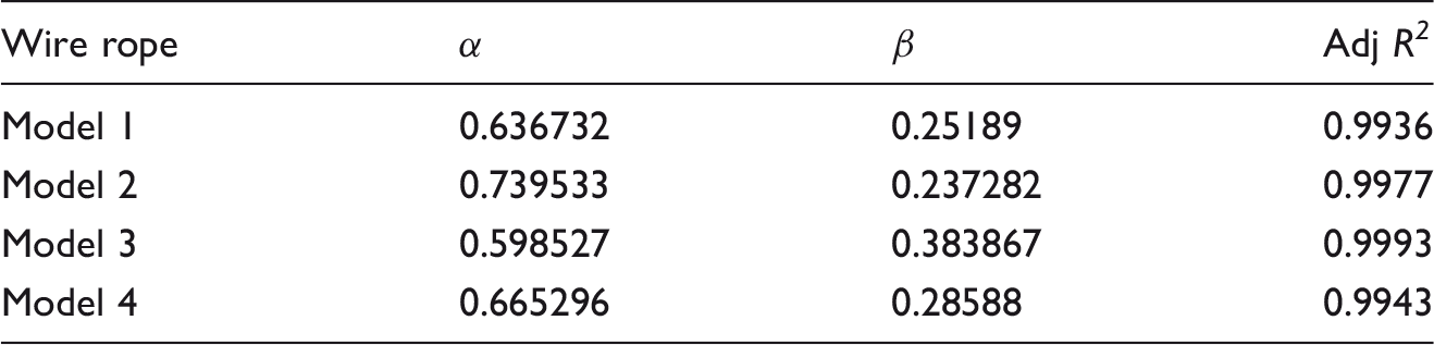
Once the stiffness characteristics were calculated, the theoretical shock response was calculated using the numerical solvers. The damping value used in the simulations was the equivalent viscous damping ratio obtained from the frequency response tests. An external excitation of 2 g amplitude half sine pulse was considered, in order to match as possible the experimental results. As mentioned previously, the SRS represents the maximum response of the SDOF system at any time, i.e. the maximum can occur either during or after the shock, for a given duration of the external pulse. Figure 11 shows the SRS for the four isolators obtained from the simulations, presented as normalized response (maximum response divided by the maximum pulse amplitude) as a function of the ratio between the duration of the pulse and the apparent natural frequency of the system. The shock response for the equivalent linear system with and without damping is also included for comparison. The theoretical shock response of the nonlinear system is much smaller compared with the linear case, but the predictions do not closely match the experimental response. This could be due to two possible reasons, one being that due to restrictions during the experiments, they did not include enough mass to provide the necessary deflection. Another limitation is the type of damping considered as an equivalent viscous ratio, and the main damping mechanism in the isolators is dry friction. However, the simulations give an insight of the improved isolation properties of the wire rope springs. A better match between theory and experiments can be obtained by loading the isolators to achieve a higher deflection near the optimum load value, thus improving the mathematical model by considering another form of damping. Such hysteresis effects are suggested for further work, as this procedure would need to characterise hysteresis loops by cyclic loading of the isolators and performing a parameter identification routine, which is out of the scope of the present paper.
Response spectra for the wire rope isolators considered. (a) Model 1, (b) Model 2, (c) Model 3 and (d) Model 4. ( linear undamped,
  linear with viscous damping
  experimental response).
Conclusions
Wire rope springs are widely used as shock isolator for extreme environments, but most of the knowledge regarding them is empirical. This work presented an overview of the experimental behaviour of the wire rope isolators focusing on static and dynamic tests. Static testing in compression shows the nonlinear stiffness behaviour, where an optimum load deflection point exists for which the stiffness is low and for higher displacements, the stiffness can be represented by a cubic hardening behaviour. The dynamic tests demonstrate that damping in wire ropes is high as long as the spring is loaded due to the relative motion in the wire strands creating friction and thus dissipating energy, plus having a low natural frequency and increasing vibration isolation efficiency. The shock response spectrum was also presented, showing improved shock isolation when compared to an equivalent mass spring damper system. Based on the experimental results, a first approach in development of a mathematical model has been presented, considering cubic stiffness in the form of a Duffing oscillator. This has shown better isolation performance compared to a linear system, and although the trend observed in the simulations is similar to the experimental results, the correlation between experimental and predicted results was not as close as expected. As a result, the development of an improved model that considers the hysteretic behaviour is suggested for further work, which would need the measurement of hysteresis loops under cyclic loading and parameter identification procedures. Moreover, different load conditions can be considered not only in compression but also in roll and shear, as this study was restricted to axial loading only.
Footnotes
Declaration of conflicting interests
The author(s) declared no potential conflicts of interest with respect to the research, authorship, and/or publication of this article.
Funding
The author(s) disclosed receipt of the following financial support for the research, authorship, and/or publication of this article: The authors received funding from the Mexican Council of Science and Technology CONACyT and Universidad Autónoma de Nuevo León for the development of this project.