
Abstract
Enormous effort has been applied to research on mufflers hybridized with a single perforated plug tube; nonetheless, mufflers conjugated with multiple parallel perforated plug tubes that disperse venting fluid and reduce secondary noise have been overlooked. To this end, an analysis of the sound transmission loss of two-chamber mufflers with multiple parallel perforated plug tubes that are optimally designed to perform within a limited space will be presented. Here, using a decoupled numerical method, a four-pole system matrix for evaluating acoustic performance (sound transmission loss) is derived. During the optimization process, a simulated annealing method, which is a robust scheme utilized to search for the global optimum by imitating a physical annealing process, is used. Prior to dealing with a broadband noise, the sound transmission loss’s maximization relative to a one-tone noise (200 Hz) is produced to check the simulated annealing method’s reliability. The mathematical model is also confirmed for accuracy. To understand the acoustical effects brought about by the various tubes (perforated tubes, internally extended non-perforated tubes, and non-perforated tubes), mufflers with internally extended non-perforated tubes and non-perforated tubes have been evaluated. The optimization of three kinds of two-chamber mufflers hybridized with one, two, and four perforated plug tubes have also been compared. The results are revealing: the acoustical performance of mufflers conjugated with more perforated plug tubes decreases as a result of the decrement of the acoustical function for acoustical elements (II) and (III). Accordingly, in order to design a better muffler, an advanced presetting of the maximum (allowable) flowing velocity is necessary before an appropriate number of perforated plug tubes can be chosen for the optimization process.
Introduction
Research on reactive mufflers was initiated in 1054 by Davis et al. 1 Studies of simple expansion mufflers based on plane wave theory were also completed.2,3 In order to increase the acoustical performance of lower frequency sound energy, Sullivan and Crocker 4 introduced a muffler equipped with an internal perforated tube. Also, a series of theories and numerical techniques for decoupling the acoustical problems have been posited to solve the coupled equations.5,6 Jayaraman and Yam, 7 presuming an unreasonable inner and outer duct, used a method for finding an analytical solution. Additionally, Rao and Munjal 8 provided a generalized decoupling method.
Now, regarding the flowing effect, Peat, 9 by finding the eigen value in transfer matrices, proposed a numerical decoupling method. However, still neglected was research work on mufflers conjugated with multiple parallel perforated plug tubes, which disperse venting fluid and reduce secondary flowing noise.
Therefore, to analyze the sound transmission loss (STL) of two-chamber mufflers equipped with multiple parallel perforated plug tubes that are optimally designed to perform within a limited space, three kinds of two-chamber mufflers linked together by multiple perforated plug tubes (muffler A: a two-chamber muffler internally equipped with one perforated plug tube; muffler B: a two-chamber muffler internally equipped with two perforated and parallel plug tubes; muffler C: a two-chamber muffler internally equipped with four perforated and parallel plug tubes) are introduced. Because the geometric shapes of mufflers A–C are complicated, the numerical method such as the finite element method10,11 will be predictably time-consuming when doing a broadband noise reduction assessment. In order to quickly and efficiently approach best design values, the numerical decoupling methods used in forming a four-pole matrix are in line with the simulated annealing method and presented in the article.
Theoretical background
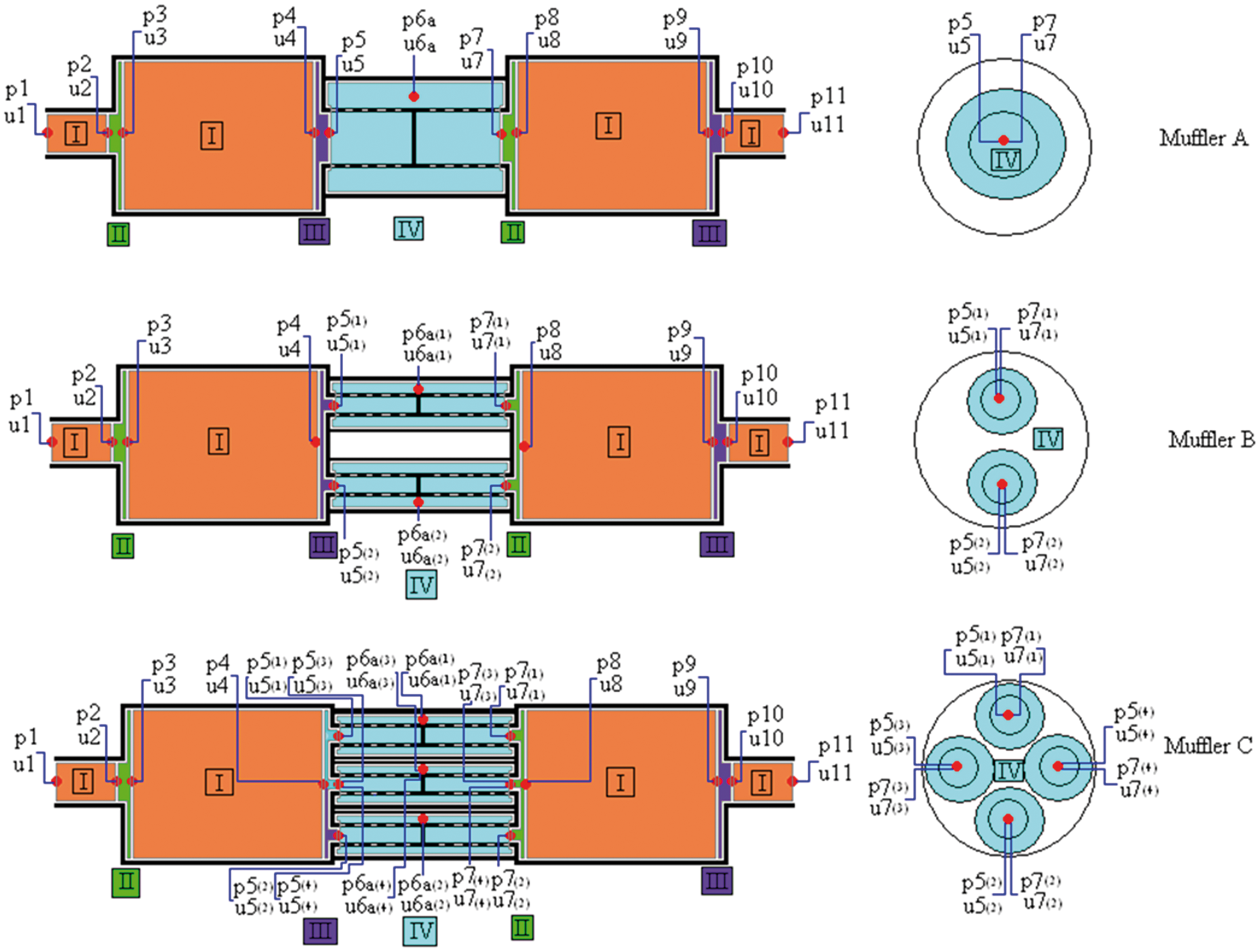
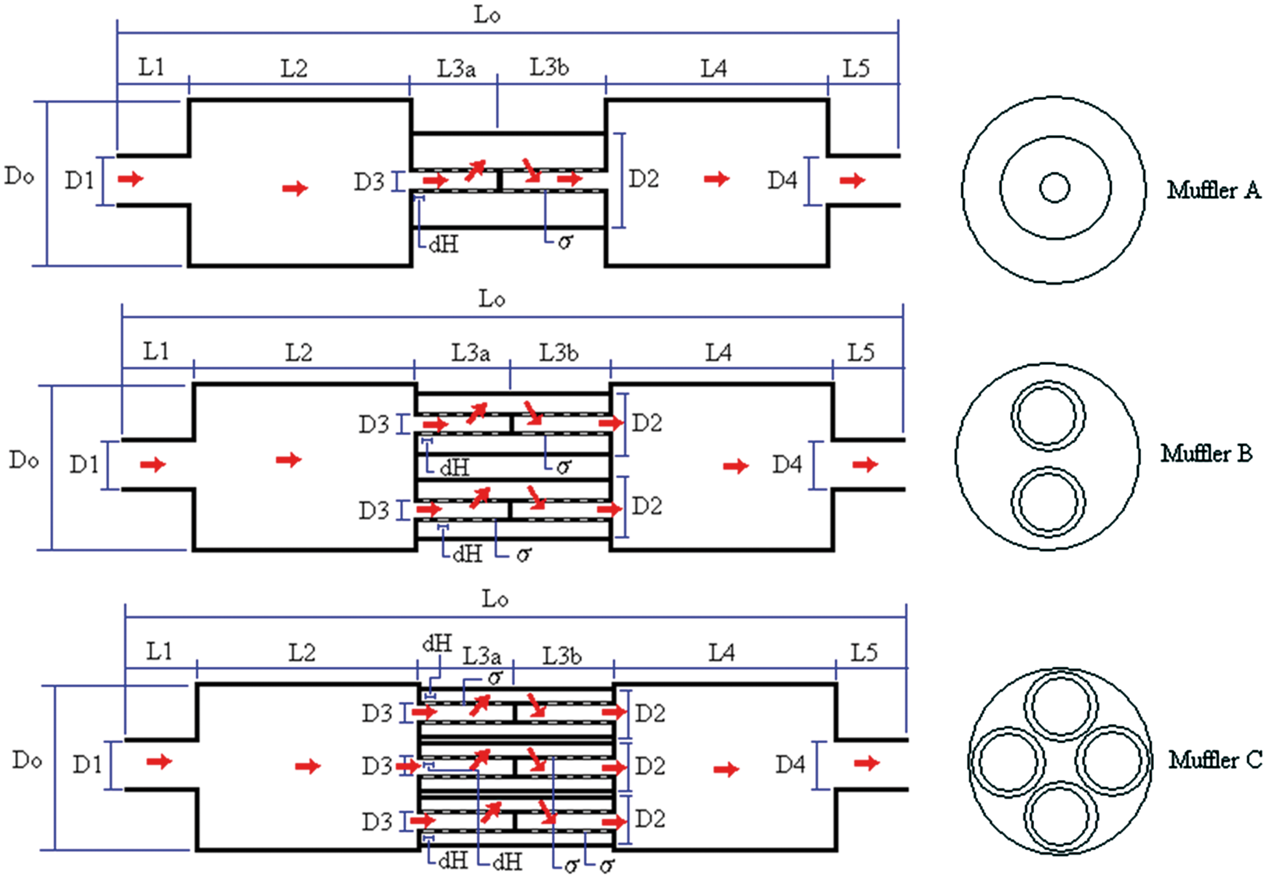
Three kinds of two-chamber mufflers connected with multiple perforated plug tubes have been adopted for noise elimination in the air compressor room shown in Figure 1. Before the acoustical fields of the mufflers were analyzed, the acoustical elements had been identified. As shown in Figure 2, four kinds of muffler components, including four straight ducts, two sudden expanded ducts, two sudden contracted ducts, and multiple perforated plug ducts, are identified and marked as I, II, III, and IV. Additionally, the acoustical field within the muffler is represented by 11 points. The outline dimension of the mufflers is shown in Figure 3. As derived in previous work12–15 and shown in Appendices 1∼4, individual transfer matrices with respect to straight ducts, perforated plug ducts, and sudden expanded/contracted ducts are described below.
Noise elimination on an air compressor room within a limited space. Acoustical elements in three kinds of two-chamber mufflers hybridized with perforated plug tubes (mufflers A to C). The outline dimension of three kinds of two-chamber mufflers internally hybridized with multiple parallel and perforated plug tubes (mufflers A to C).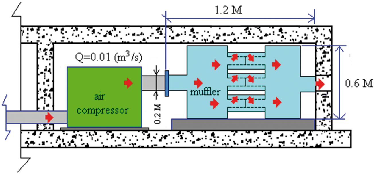
Muffler A (a two-chamber muffler connected with one perforated plug tubes)
As derived in previous work,12–15 for the acoustical element (I) shown in Figure 2, the four-pole matrix between nodes 1 and 2 is

For the acoustical element (II), the four-pole matrix between nodes 2 and 3 is

Similarly, the four-pole matrix between nodes 3 and 4 is

For the acoustical element (III), the four-pole matrix between nodes 4 and 5 is

As shown in previous work12–15 and derived in Appendices 1 and 2, for an acoustical element (IV), which is composed of two acoustical parts (one, an expanded perforated plug tube; and the other, a contracted perforated plug tube), the four-pole matrix between nodes 5 and 6a and nodes 6a and 7 is


Combining equations (5)–(6), the four-pole matrix between nodes 5 and 7 yields

Likewise, the four-pole matrix between nodes 7 and 8 for a sudden expanded duct is

The four-pole matrix between nodes 8 and 9 in a straight duct is

The four-pole matrix between nodes 9 and 10 for a sudden contracted duct is

Moreover, the four-pole matrix between nodes 10 and 11 in a straight duct is

The total transfer matrix assembled by multiplication is
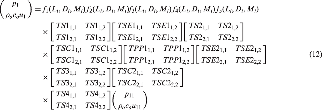
A simplified form is expressed in a matrix as

Muffler B (a two-chamber muffler connected with two perforated plug tubes)
Similarly, the acoustical four-pole matrix between nodes 1∼2, nodes 2∼3, nodes 3∼4, nodes 8∼9, nodes 9∼10, and nodes 10∼11 is the same as equations (1)–(3) and equations (7)–(11). As derived in Appendix 3, for two parallel perforated plug tubes connected to two chambers, the four-pole matrices between nodes 5(1)∼7(1) and nodes 5(2)∼7(2) can be combined to an equivalent matrix

The equivalent acoustical field of muffler B is shown in Figure 4. Consequently, the total transfer matrix assembled by multiplication is
Equivalent acoustical field for a muffler hybridized with perforated plug tubes (mufflers B and C).

A simplified form is expressed in a matrix as

Muffler C (a two-chamber muffler connected with four perforated plug tubes)
The acoustical four-pole matrix between nodes 1–2, nodes 2–3, nodes 3–4, nodes 8–9, nodes 9–10, and nodes 10–11 is the same as equations (1)–(3) and equations (9)–(11). As derived in Appendix 4, for a two chambers muffler connected with four parallel perforated plug tubes, the four-pole matrices between nodes 5(1)–7(1), 5(2)–7(2), 5(3)–7(3), and 5(4)–7(4) nodes can be combined to an equivalent matrix

The related equivalent acoustical field of muffler C is also presented and shown in Figure 4. Consequently, the total transfer matrix assembled by multiplication is
A simplified form is expressed in a matrix as

Overall sound power level
The STL of mufflers A–C are defined as
16


The silenced octave sound power level emitted from a muffler’s outlet is

Finally, the overall SWLT silenced by a muffler at the outlet is
Objective function
STL maximization for a tone (f) noise
The objective functions in maximizing the STL at a pure tone (f) are


The related ranges of the parameters are
SWL minimization for a broadband noise
To minimize the overall SWLT, the objective function is


Model check
Before performing the simulated annealing (SA) optimal simulation on mufflers, an accuracy check of the mathematical model on a one-chamber muffler with one perforated plug tube is performed by Sullivan and Crocker.
4
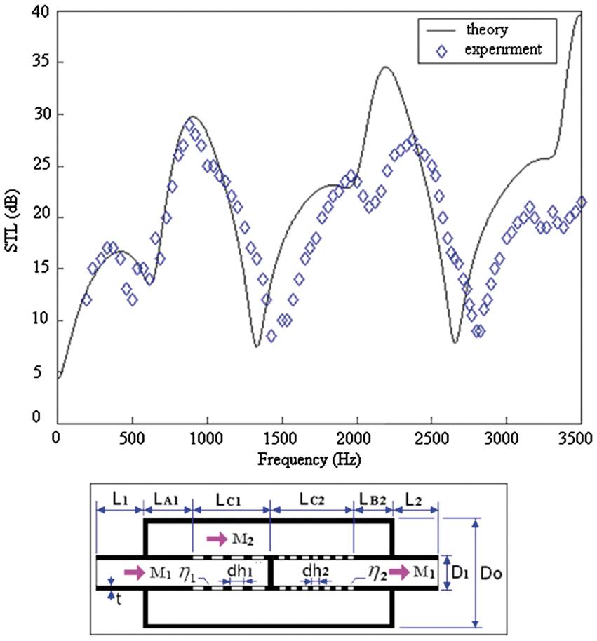
As indicated in Figure 5, comparisons between theoretical data and experimental data are in agreement. Therefore, the model of two mufflers connected with multiple perforated plug tubes is adopted in the following optimization process.
Performance of an acoustical element of a one perforated plug tube with the mean flow (M1 = M2 = 0.05, D1 = 0.0493 (m), Do = 0.1016 (m), LC1 = LC2 = 0.1286 (m), L1 = L2 = 0.1 (m), LA1 = LB2 = 0.0 (m), t = 0.081 (m), dh1 = dh2 = 0.00249 (m), η1 = η2 = 0.037), experimental data is from Sullivan and Crocker.
4
Case studies
Unsilenced SWL of an air compressor inside a duct outlet.
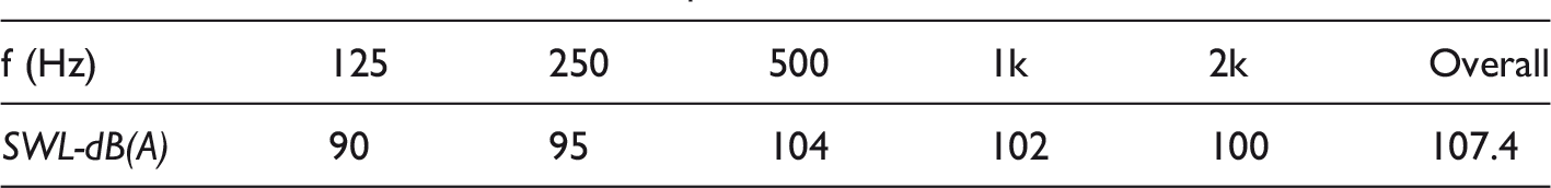
It is obvious that the octave band frequencies (125 Hz, 250 Hz, 500 Hz, 1000 Hz, and 2000 Hz) have higher noise levels (90∼104 dB). To reduce the huge venting noise emitted from the air compressor’s outlet, the noise elimination on the five primary noises using the two-chamber mufflers connected with multiple perforated plug tubes (mufflers A∼C) that disperse venting fluid and decrease the secondary flowing noise is considered.
To obtain the best acoustical performance within a fixed space, numerical assessments linked to a SA optimizer are applied. Before the minimization of a broadband noise is performed, a reliability check of the SA method by maximization of the STL at a targeted tone (200 Hz) is performed. As shown in Figure 1, the available space for a muffler is 0.6 m in width, 0.6 m in height, and 1.2 m in length. The flow rate (Q) and thickness of a perforated tube (t) are preset at 0.01 (m3/s) and 0.001 (m), respectively. The corresponding OBJ functions, space constraints, and the ranges of design parameters are summarized in equations (23)∼(24).
Simulated annealing method
Evolutionary Algorithms (EAs), which search for appropriate global solution in engineering problems, have, for two decades, been laboriously elaborated upon. It should also be noted that as a stochastic search method, SA is recognized as one of the best. Further, prior to SA optimization, the need to choose starting data which is necessary for the classical gradient methods of EPFM, IPFM and FDM 17 has been eliminated. As a result, for use in a muffler’s shape optimization, SA is designated as an optimizer.

The pseudo-code implementing the simulated annealing heuristic.
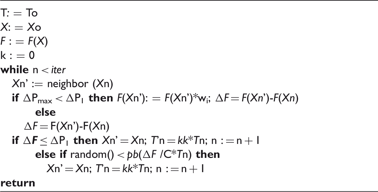
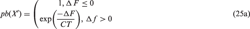
For the purpose of escaping the local optimum, SA also permits movement that results in solutions that are inferior (uphill movement) to the current solution. Hence, if the transition property (pb(X′)) is greater than a random number of rand(0,1), the new inferior solution which results in a higher energy condition will be accepted; otherwise, it will be rejected. Each successful substitution of the new current solution will conduct to the decay of the current temperature as

Results and discussion
Results
The accuracy of the SA optimization depends on two kinds of SA parameters including kk (cooling rate) and iter (maximum iteration). To achieve good optimization, the following parameters are varied step by step:20,21
kk (0.91, 0.93, 0.95, 0.97, 0.99); iter (25, 50, 100, 500, 1000, 2000).
Two results of optimization (one, pure tone noises used for SA’s accuracy check; and the other, a broadband noise occurring in an air compressor room) are described below.
Pure tone noise optimization
Muffler A
Optimal STL for muffler A (equipped with one perforated plug tube) at various SA parameters (targeted tone of 200 Hz).
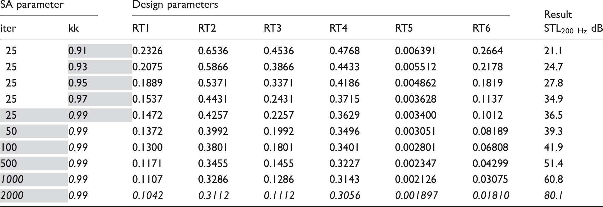
Note. The gray shades mean the SA parameters that are adjusted during the the optimization serarching process.
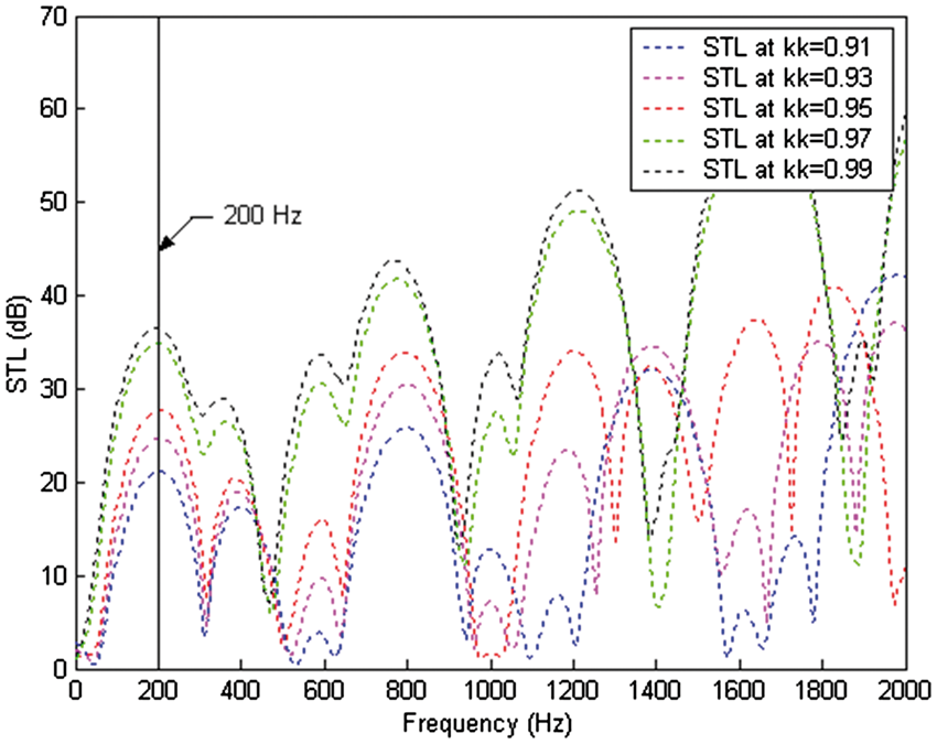
STL with respect to various kk (muffler A: iter = 25, target tone = 200 Hz).
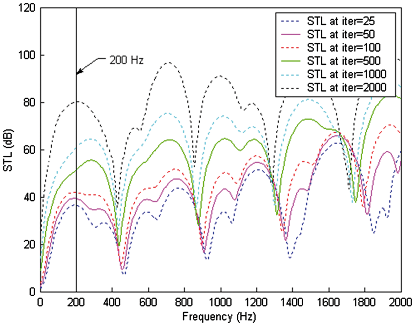
STL with respect to various iter (muffler A: kk = 0.99, target tone = 200 Hz).
Mufflers D and E
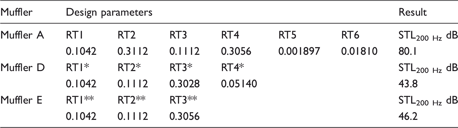
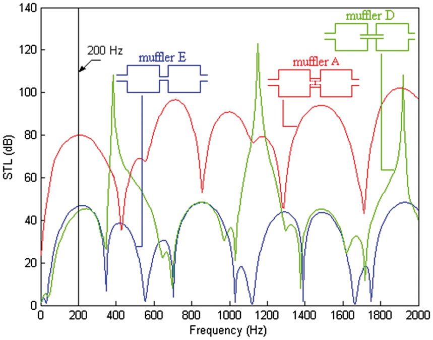
As indicated in Figure 8, to appreciate the acoustical performance of two-chamber mufflers equipped with various tubes (muffler D: a muffler equipped with one non-perforated and internally extended tube; muffler E: a muffler equipped with one non-perforated tube), the shape optimization of mufflers D and E at 200 Hz is also performed using the same SA parameters of (kk, iter) = (0.99, 2000). The optimal design parameters for mufflers A, D, and E are summarized in Table 4 and plotted in Figure 9. As indicated in Figure 9, the optimal STLs for mufflers A, D, and E have been precisely located at the specified frequency of 200 Hz. As indicated in Table 4 and Figure 9, the STL of muffler A at 200 Hz reaches 80.1 dB. In addition, the STLs with respect to mufflers D and E are 43.8 dB and 46.2 dB. Consequently, muffler A with a perforated plug tube reach is superior to other mufflers. Moreover, the acoustical performances of both mufflers D and E at a specified 200 Hz are almost the same.
The outline dimension of three kinds of mufflers hybridized with various tube (mufflers A, D, and E). Comparison of the optimal STL for mufflers A, D, and E (targeted tone of 200 Hz). Note: Muffler D: RT1* = D2; RT2* = D3; RT3* = L2; RT4* = L4. Muffler E: RT1** = D2; RT2** = D3; RT3** = L2. Comparison of the optimal STLs of three kinds of mufflers (mufflers A, D, and E) optimization at pure tone of 200 Hz.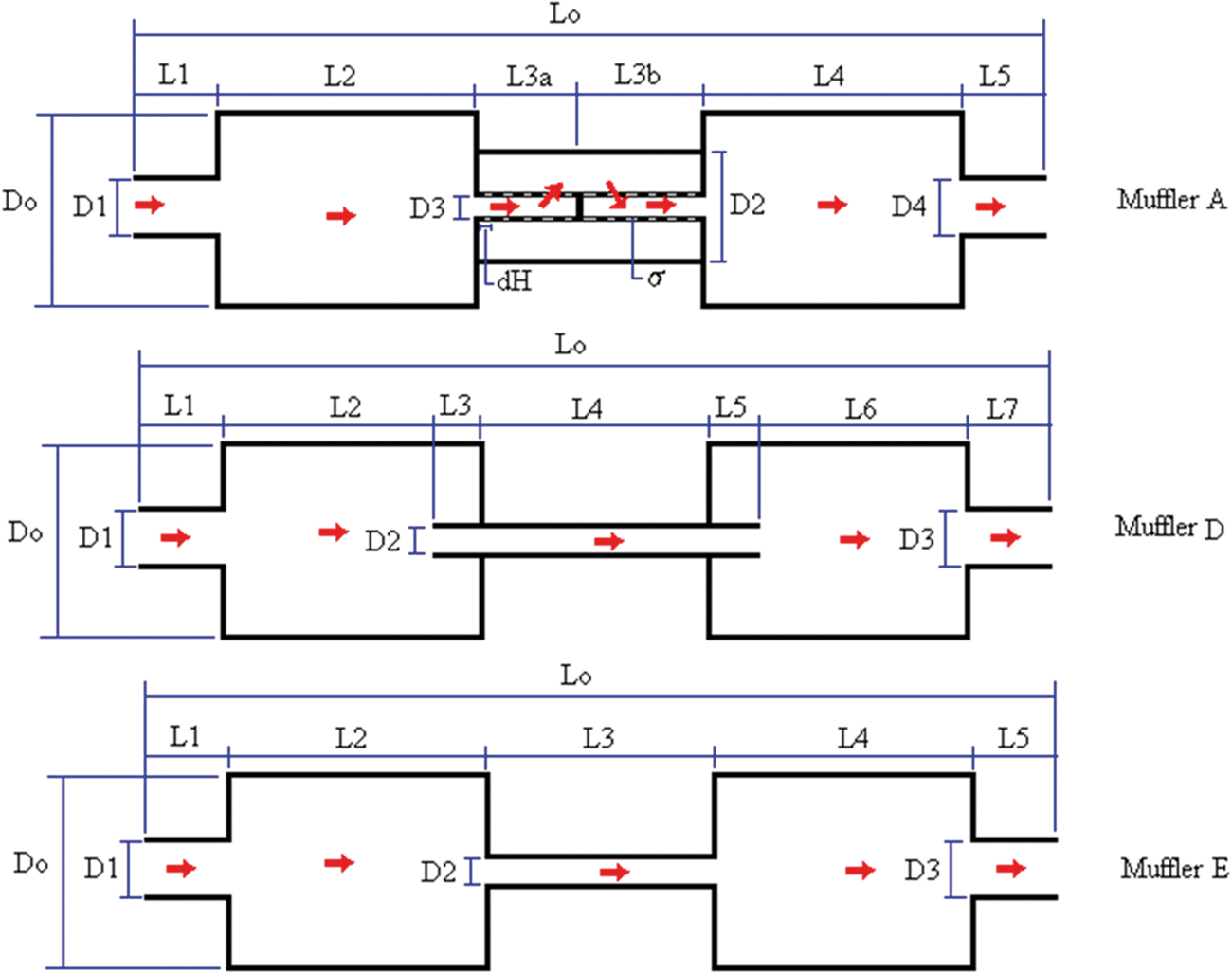
Broadband noise optimization
Mufflers A–C
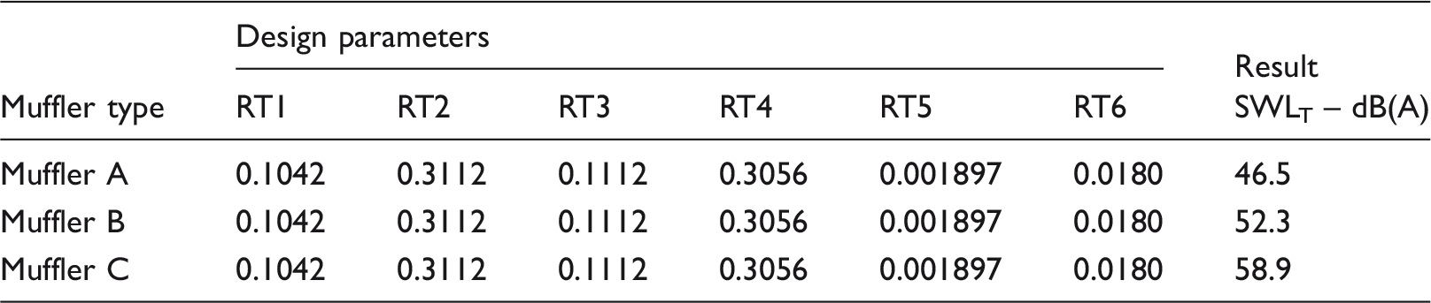
Comparison of the minimized SWLT of three kinds of mufflers (mufflers A∼C) (broadband noise).
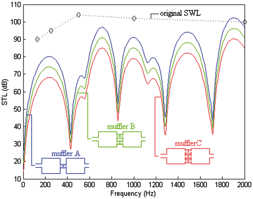
Comparison of the optimal STLs of three kinds of mufflers (mufflers A, B, and C) and the original SWL.
Mufflers F and G
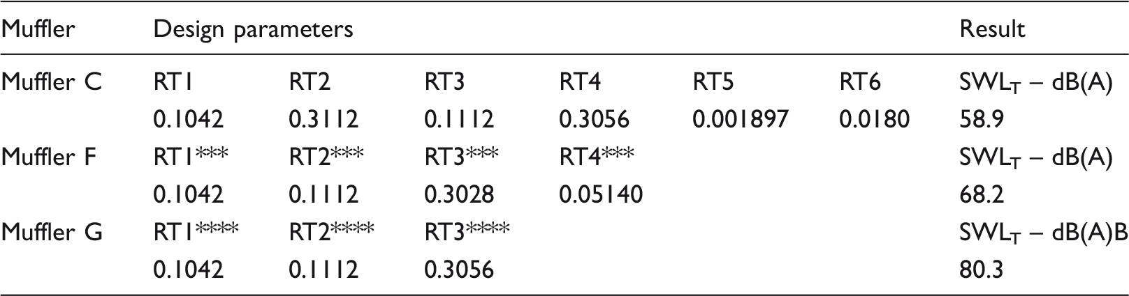
As indicated in Figure 11, to appreciate the acoustical performance of two-chamber mufflers equipped with various tubes (muffler F: a muffler equipped with four non-perforated and internally extended tubes; muffler G: a muffler equipped with four non-perforated tubes), the shape optimization of mufflers F and G for a broadband noise is also performed using the same SA parameters of (kk, iter) = (0.99, 2000). The optimal design parameters for mufflers C, F, and G are summarized in Table 6 and plotted in Figure 12. As illustrated in Table 6, the resultant sound power levels with respect to three kinds of mufflers (mufflers C, F, and G) have been reduced from 107.4 dB to 58.9 dB, 68.2 dB, and 80.3 dB.
The outline dimensions of three kinds of mufflers hybridized with various tubes (mufflers C, F, and G). Comparison of the optimal STLs of three kinds of mufflers (mufflers C, F, and G) and the original SWL. Comparison of the optimal STL for mufflers C, F, and G (broadband noise). Note: Muffler F: RT1*** = D2; RT2*** = D3; RT3*** = L2; RT4* = L4. Muffler G: RT1**** = D2; RT2**** = D3; RT3**** = L2.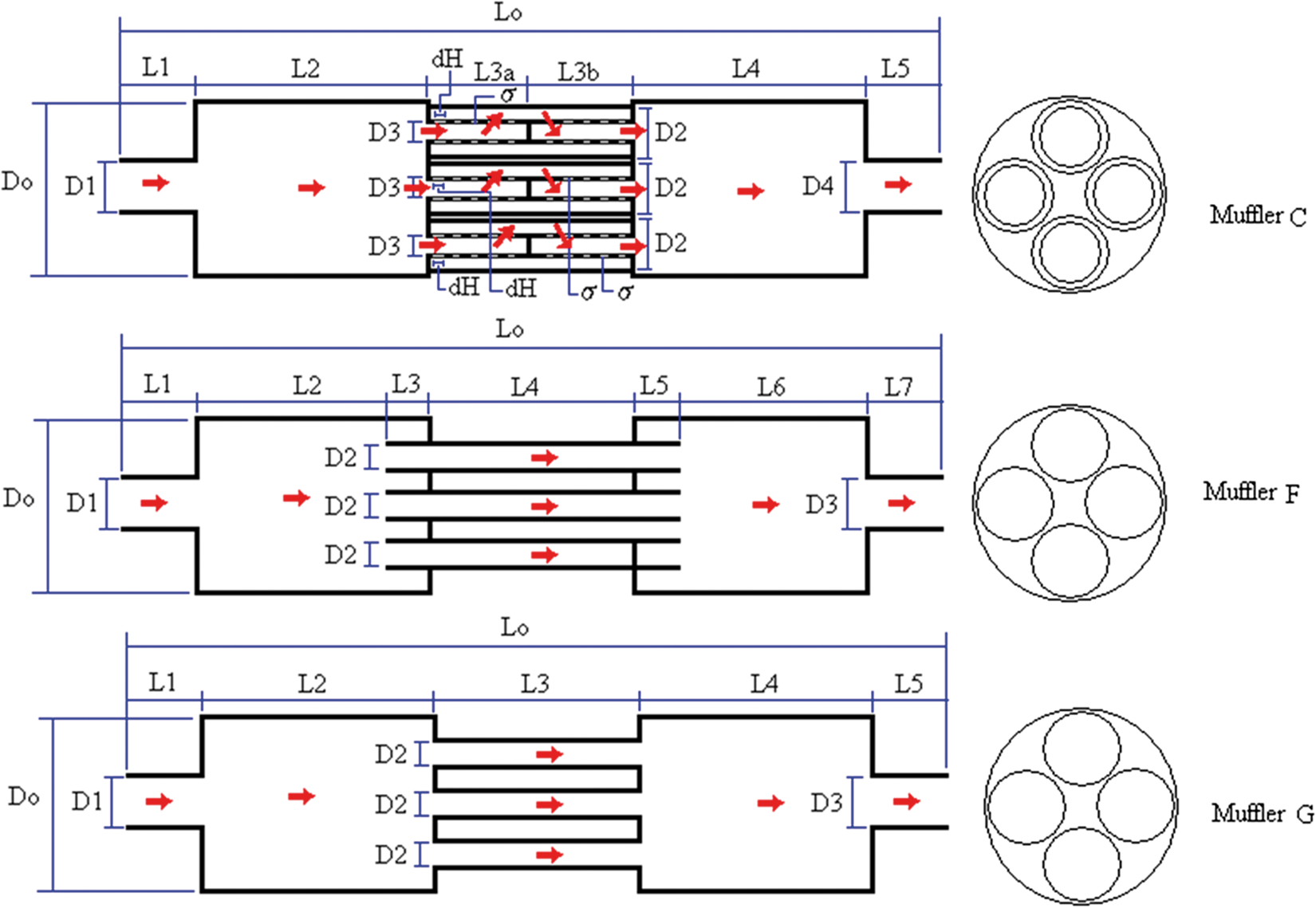
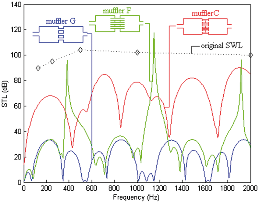
As indicated in Figure 12, muffler A with four perforated plug tubes is superior to other mufflers. Moreover, muffler G with four non-perforated tubes has the worst acoustical performance.
Discussion
In order to decrease the secondary flowing noise generated from the higher speed flow, new muffler designs with multiple perforated plug tubes are presented. To achieve a sufficient optimization, the selection of the appropriate SA parameter set is essential. As indicated in Table 3, the best SA set of muffler A at the targeted pure tone noise of 200 Hz has been shown. The related STL curves with respect to various SA parameters are plotted in Figures 6 and 7. Figures 6 and 7 reveal that the predicted maximal value of the STL is located at the desired frequency. Similarly, in dealing with pure tone noise (200 Hz) in mufflers D and E, the profile shown in Figure 9 indicates that the maximum STLs of the mufflers are also located at the specified frequency.
In dealing with the broadband noise, the acoustical performance among three kinds of two-chamber mufflers connected with multiple perforated plug tube (mufflers A, B, and C) are shown in Table 5 and Figure 10. As can be observed in Table 5, the overall STL of the two-chamber muffler equipped with one perforated plug tube (muffler A) reaches 60.9 dB. However, the overall STLs of the two-chamber mufflers equipped with two perforated plug tubes (muffler B) and four perforated plug tubes (muffler C) are 55.1 dB and 48.5 dB.
Here, for the broadband noise optimization in Table 5, the related cutoff frequencies
To appreciate the acoustical effect of the perforated plug tubes (mufflers A∼C), the internally extended non-perforated tubes (mufflers D and F), and the non-perforated tubes (mufflers E and G), a comparison of the mufflers’ acoustical performance is carried out and shown in Tables 4 and 6 and Figures 9 and 12. As illustrated in Table 4 and Figure 9, when dealing with a pure tone noise, muffler A with a perforated plug tube is superior to those mufflers having a non-perforated tube and an internally expanded non-perforated tube. Similarly, when dealing with a broadband noise, the overall STLs with respect to mufflers C, F, and G shown in Table 6 and Figure 12 are 48.5 dB, 39.2 dB, and 27.1 dB. It is obvious that a two-chamber muffler equipped with multiple perforated plug tubes is also superior to these muffler equipped with multiple expended/ non-extended non-perforated tubes.
Moreover, the results shown in Table 5 and Figure 10 indicate that the two-chamber muffler hybridized with fewer perforated plug tubes is superior to mufflers that are equipped with more perforated plug tubes. It is obvious that for the mufflers equipped with more perforated plug tubes, the acoustical performances of the acoustical element (II) between nodes 4 and 5 and acoustical element (III) between nodes 7 and 8 will largely decrease due to the decrement of the area ratio. Therefore, the overall noise reduction of the mufflers with more perforated plug tubes will decrease.
Conclusion
It has been shown that two-chamber mufflers hybridized with multiple perforated plug tubes can be easily and efficiently optimized within a limited space by using a decoupling technique, a plane wave theory, a four-pole transfer matrix, and a SA optimizer. As indicated in Table 3 and Figures 6 and 7, two kinds of SA parameters (kk and iter) play essential roles in the solution’s accuracy during SA optimization. Figures 6, 7, and 9 indicate that the tuning ability established by adjusting design parameters of mufflers A, D, and E is reliable.
Additionally, as indicated in Tables 4 and 6 and Figures 9 and 12, the acoustical effect of various tubes has been discussed. Results reveal that the acoustical performance of the perforated plug tubes is superior to other tubes (internally extended non-perforated tubes and non-perforated tubes). Moreover, appropriate design parameters of three kinds of the mufflers hybridized with multiple perforated plug tubes (mufflers A∼C) has been assessed. As indicated in Table 5, the resultant SWLT with respect to these mufflers is 46.7 dB, 52.3 dB, and 58.9 dB. Obviously, the two-chamber muffler hybridized with fewer perforated plug tubes is superior to the mufflers equipped with more perforated plug tubes. It can be seen that more perforated plug tubes installed between the two-chamber muffler will disperse the venting fluid and reduce the secondary flowing noise; however, the acoustical performances of the acoustical element (II) between nodes 4 and 5 and acoustical element (III) between nodes 7 and 8 will decrease even though the parallel perforated plug tubes for the mufflers have increased. Therefore, before choosing the appropriate number of perforated plug tubes and performing the muffler’s shape optimization, presetting the maximum flowing velocity within the muffler is required.
Footnotes
Declaration of conflicting interests
The author(s) declared no potential conflicts of interest with respect to the research, authorship, and/or publication of this article.
Funding
The author(s) disclosed receipt of the following financial support for the research, authorship, and/or publication of this article: The author acknowledges the financial support of the National Science Council (NSC 99-2622-E-235-002-CC3, ROC).