
Abstract
This paper presents the design, fabrication and testing of an innovative active seat suspension system for heavy-duty vehicles. Rather than using conventional linear actuators, such as hydraulic cylinders or linear motors, which need to be well maintained and are always expensive when high force outputs are required, the proposed seat suspension system directly applies a rotary motor in order to provide the required active actuation, without changing the basic structure of the existing off-the-shelf seat suspension. A gear reducer is also applied to amplify the output torque of the motor so that a high output torque can be achieved using a low rated power motor. A static output feedback
Introduction
Drivers of heavy-duty vehicles are often exposed to severe vibration transferred from rough road and operation tools, and the vibration magnitude levels for heavy-duty vehicles are several times higher than those of passenger vehicles. Agricultural vehicles and industrial vehicles, in particular, need to work in harsh environments for a longer period of time. Thus, drivers of heavy-duty vehicles often suffer from the highest incident rates of injuries causing low back pain while working. This has resulted in an increasing demand for improvement of ride comfort of heavy-duty vehicles. 1 Tyres, seat suspension and chassis suspension are mostly considered for isolating vehicle vibration. Generally, it is impossible to modify the tyre parameters when the tyres are chosen. Even though many different approaches have been proposed to improve the chassis suspension performance, the chassis suspension movements of heavy-duty vehicles are always related to the operation tool performance, and driver comfort is often compromised. On the other hand, the seat suspension can be independent from the chassis suspension system and can isolate vibration transmitted directly to drivers. For this reason, a number of different types of seat suspension have been applied to heavy-duty vehicles in order to improve drivers’ working conditions2,3 because they can be more easily modified and optimized. Now the seat suspension has become a simple and effective method to isolate the vehicle vibration transmitted to the driver’s body.
There are three main kinds of seat suspension reported in the literature. These are passive, active and semi-active suspension. Traditional passive seat suspension’s natural frequency is usually between 1.5 and 4 Hz. This may limit the seat performance in the low frequency range because heavy-duty vehicles normally suffer from high levels of vertical vibration in the frequency range of 1–20 Hz, especially from 3 to 5 Hz,4,5 and hence, passive suspension could amplify vibration in the low frequency range so that ride comfort is affected. To overcome this problem, many different approaches have been proposed. For example, Le and Ahn 6 proposed a negative stiffness structure for passive suspension in low frequency. Maciejewski et al. 7 studied possibilities for improving the vibro-isolation properties of a seat suspension with an air-spring and shock absorber. Holtz and Van Niekerk 8 designed a seat suspension with an air-spring and auxiliary volume for typical articulated or rigid frame dump trucks. Quasi-zero-stiffness devices and structures have also been studied for passive vibration isolation.9,10 In recent years, much research has been conducted into seat suspensions with semi-active devices. Choi et al.11,12 proposed semi-active seat suspensions using an electrorheological fluid damper and a magnetorheological (MR) fluid damper. Sun et al. 13 proposed an MR elastomer-based isolator for horizontal vibration reduction of a driver seat. MR dampers used for helicopter crew seats to enhance occupant comfort have been studied in Hiemenz et al. 14 On the other hand, active suspension has attracted more and more attention in recent years because it is widely accepted that an active suspension is the most effective way to improve suspension performance. Gan et al. 15 presented an active seat suspension with two electromagnetic linear actuators. Maciejewski et al. 16 proposed an active seat suspension system comprised of a hydraulic absorber and a controlled air-spring. Kawana and Shimogo 17 used an electric servomotor with a ball screw mechanism as the active seat suspension actuator. Ahn 18 proposed an active pneumatic vibration isolation system using negative stiffness structures. One of the main problems, however, is how to make use of active suspension without incurring high cost.
For both semi-active and active suspensions, there are also many reputable control strategies proposed, e.g.
In the above-mentioned literature, direct force output actuators, such as a single-controlled pneumatic spring
16
and a linear motor,
23
have been chosen. These force output devices have the disadvantages of requiring big external power supplies and high cost when high force output is required. To overcome these drawbacks, in this study, an innovative active seat suspension is proposed. Due to the widespread application of rotary motors, their costs are cheaper than their linear counterparts. There are studies with rotary motors for active suspension using a screw mechanism
17
and a rack/pinion device,
28
where these mechanisms have been utilized to transform torque into vertical force. In this paper, the torque of a rotary motor is amplified via a gear reducer and exerted directly on the scissor structure centre of the seat suspension. This means that a low rated power motor can be used and this will decrease the cost of an active seat suspension greatly. The proposed active seat suspension prototype is also easily fabricated through the use of a commercial passive seat suspension. Based on the identified model parameters, a friction force compensation-based
The remainder of the paper is organized as follows: the next section presents the innovative active seat suspension design and identifies its parameters. The static output feedback
Notation: I is used to denote the identity matrix of appropriate dimensions. * is used to represent a term that is induced by symmetry.
Innovative active seat suspension design
Seat suspension design
Electrical rotary motors are widely used in many areas. They have many advantages compared to linear actuators, such as lower price and ease of installation and control. In order to further reduce the actuator cost, a gear reducer can be applied to amplify the motor’s torque output. Thus, a low rated power motor can be used for active vibration control. Figure 1 shows a prototype of the proposed rotary motor-based active seat suspension. It is modified from a conventional commercial vehicle seat (GARPEN GSSC7) in which the original damper has been removed. The new torque output module consisting of one servo motor and one gear reducer is installed on the left side of the scissor structure of the seat suspension, and an additional gear reducer is assembled on the other side of the suspension in order to balance the friction force generated by the gear reducer. A further upgrade of this seat suspension to include an innovative rotary damper on this side is investigated but will not be discussed in this paper. The servo motor and gear reducer are connected in series. The gear reducer is installed on the rotation centre of the scissor structure. The gear reducer’s case is fixed on the outside of the scissor bar, and the shaft is fixed on another bar.
A prototype of the proposed active seat suspension.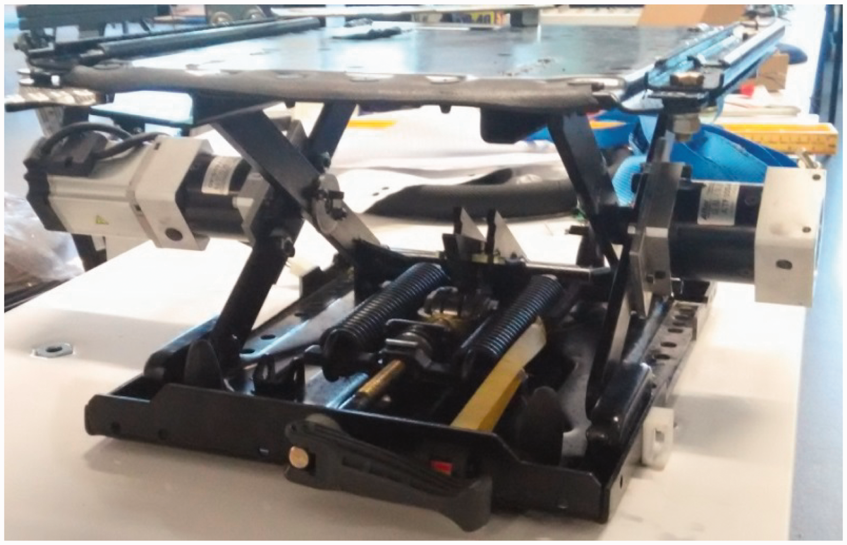
A 400 W Panasonic servo motor (MSMJ042G1U) is used and is powered by a Panasonic servo driver (MBDKT2510CA1) which can control the torque output of the motor accurately. The rated torque output of the motor is 1.3 N m and the gear reducer ratio is 40:1, so the torque output can be amplified 40 times to a maximum of 52 N m.
Figure 2 shows a schematic diagram of the suspension design, where the follower and the cam compose a cam mechanism. The cam is fixed with the outside scissor bar and can push the follower to move along its guide. Then the follower can extrude the spring. The external load can be supported by the spring force.
Schematic diagram of the active seat suspension design.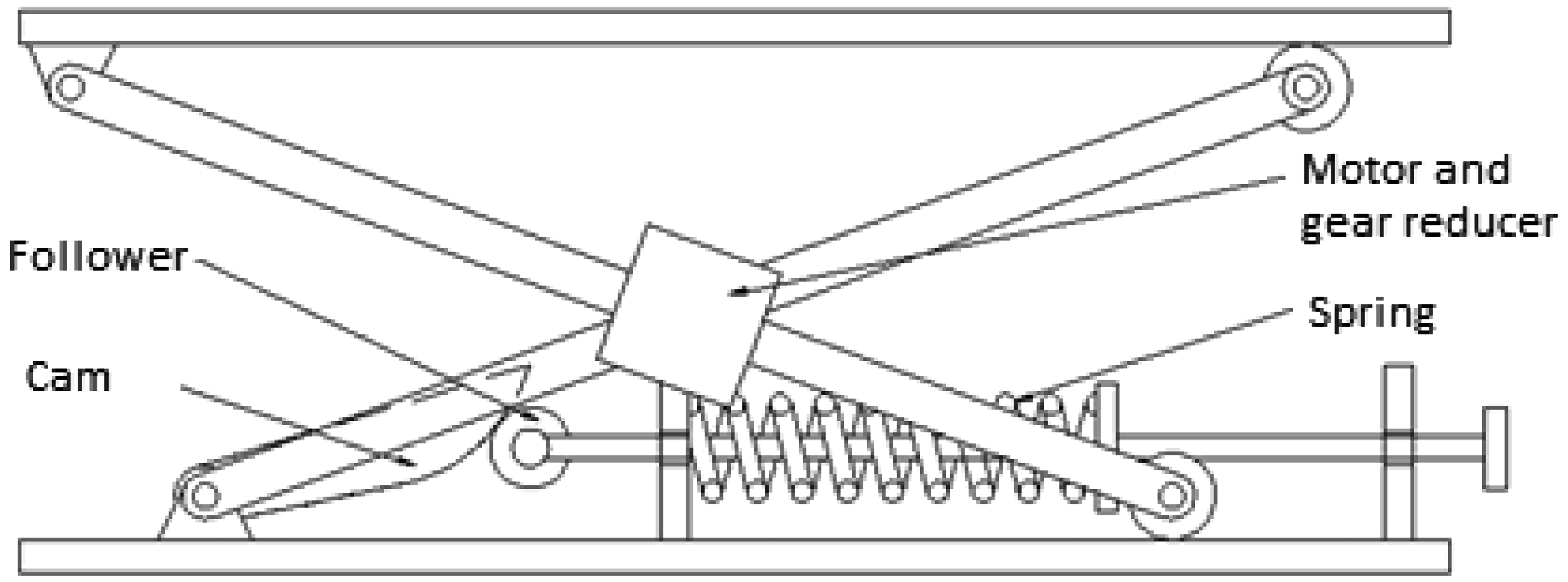
Friction model identification
The newly designed seat suspension’s dynamic performance was tested in the laboratory by MTS machine (Load Frame Model: 370.02, MST Systems Corporation) as shown in Figure 3. The MTS machine can hold the suspension with its upper and lower heads. The upper head, which is driven by a hydraulic cylinder, moves in sinusoidally with a 5 mm amplitude and at two excitation frequencies of 1 and 2 Hz. The force generated by the suspension was measured using a load cell mounted below the lower head, which was fixed to the machine bottom (see Figure 3). The force measured by the load cell is defined as
MTS machine testing. MTS:. Friction force–displacement relationship of the seat suspension. Friction force–velocity relationship of the seat suspension.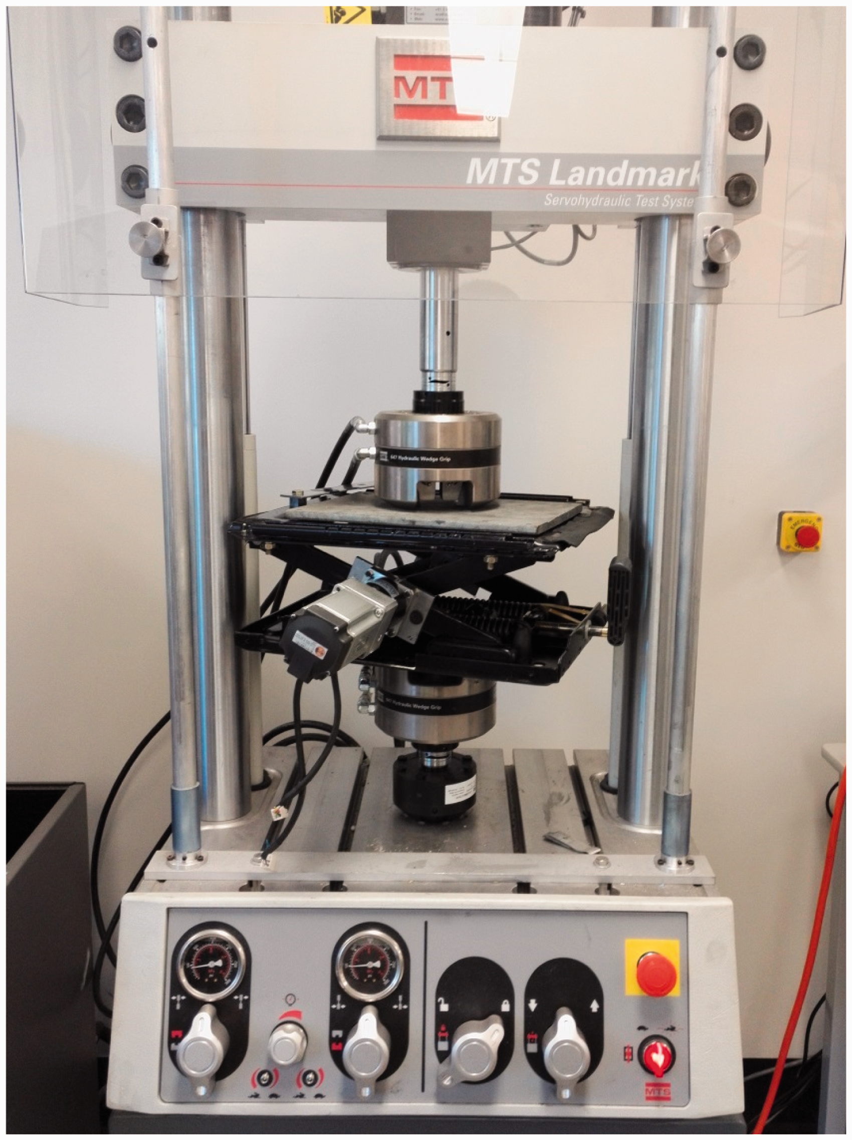
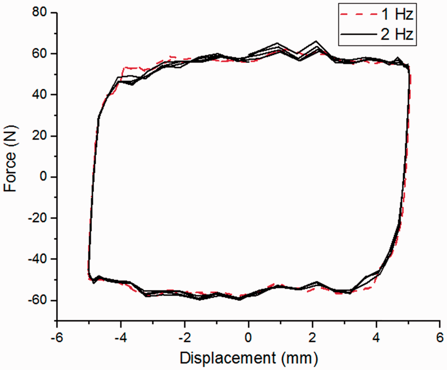
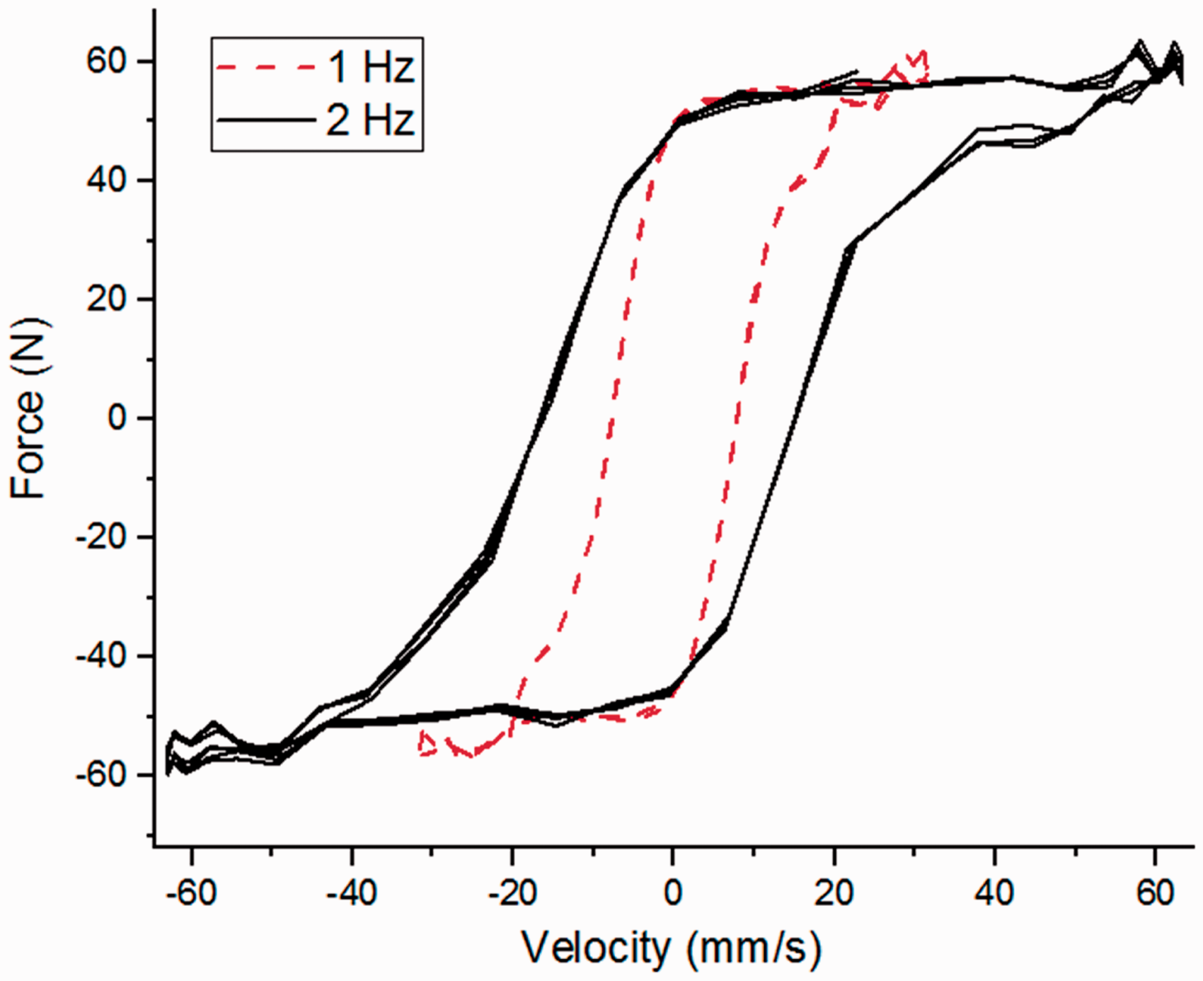

The friction force can be defined as a hysteresis model and is given by
Friction model simulation in (a) 1 Hz and (b) 2 Hz.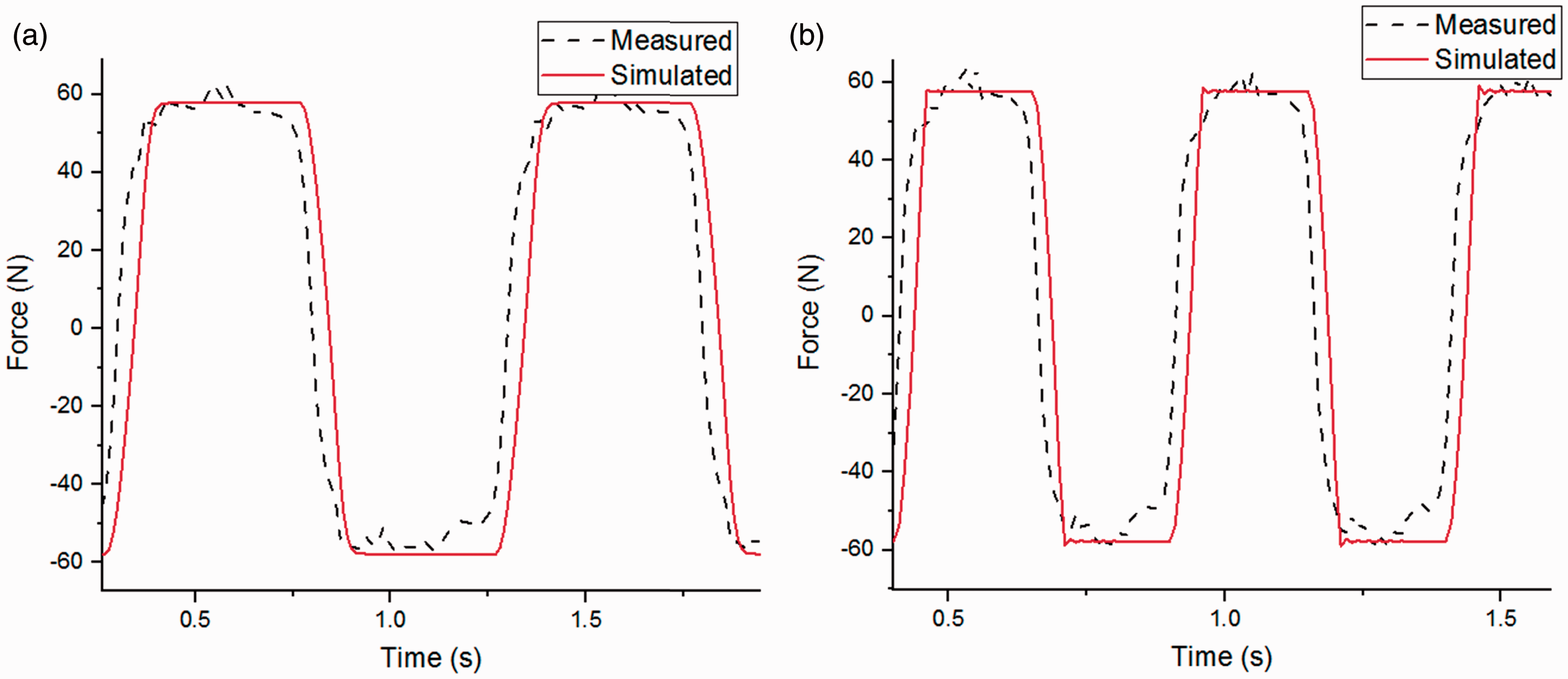


Torque to force transformation
As the rotatory motor can only output torque T to the seat scissor structure, the torque needs to be equivalent to a vertical force F exerted on the seat based on the geometry of the structure. Figure 7 shows the equivalent relationship between the torque applied on one suspension bar and the force to the seat. Due to the torque interaction between the two scissor bars, each bar exerts half of the force on the seat. The relationship of the torque output and the equivalent vertical force is given as
Force analysis of one suspension strut bar.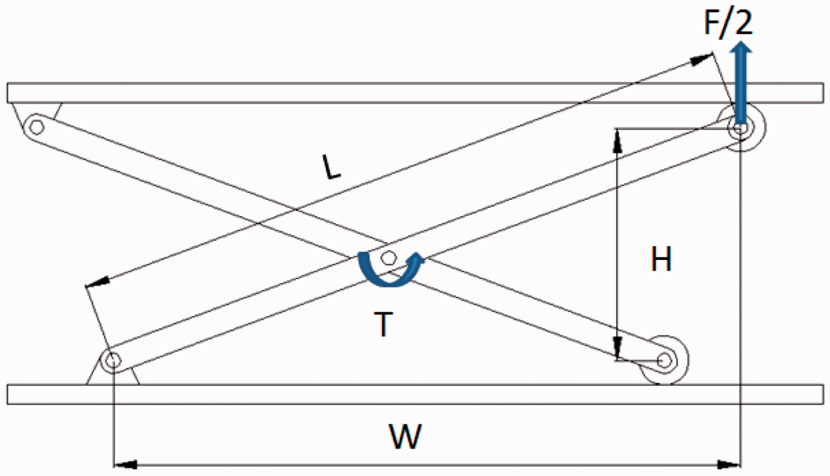

controller design with friction compensation
Static output feedback controller
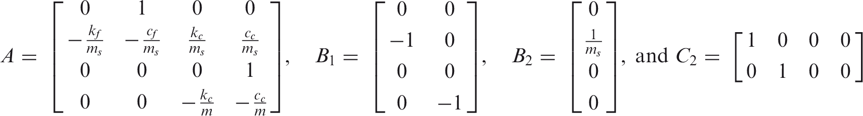
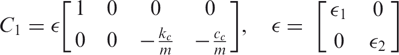
Figure 8 shows a simplified seat suspension model with suspension stiffnesskf, suspension damping coefficientcf, cushion stiffnesskc, cushion damping coefficientcc, friction forcefr and active force Seat suspension model.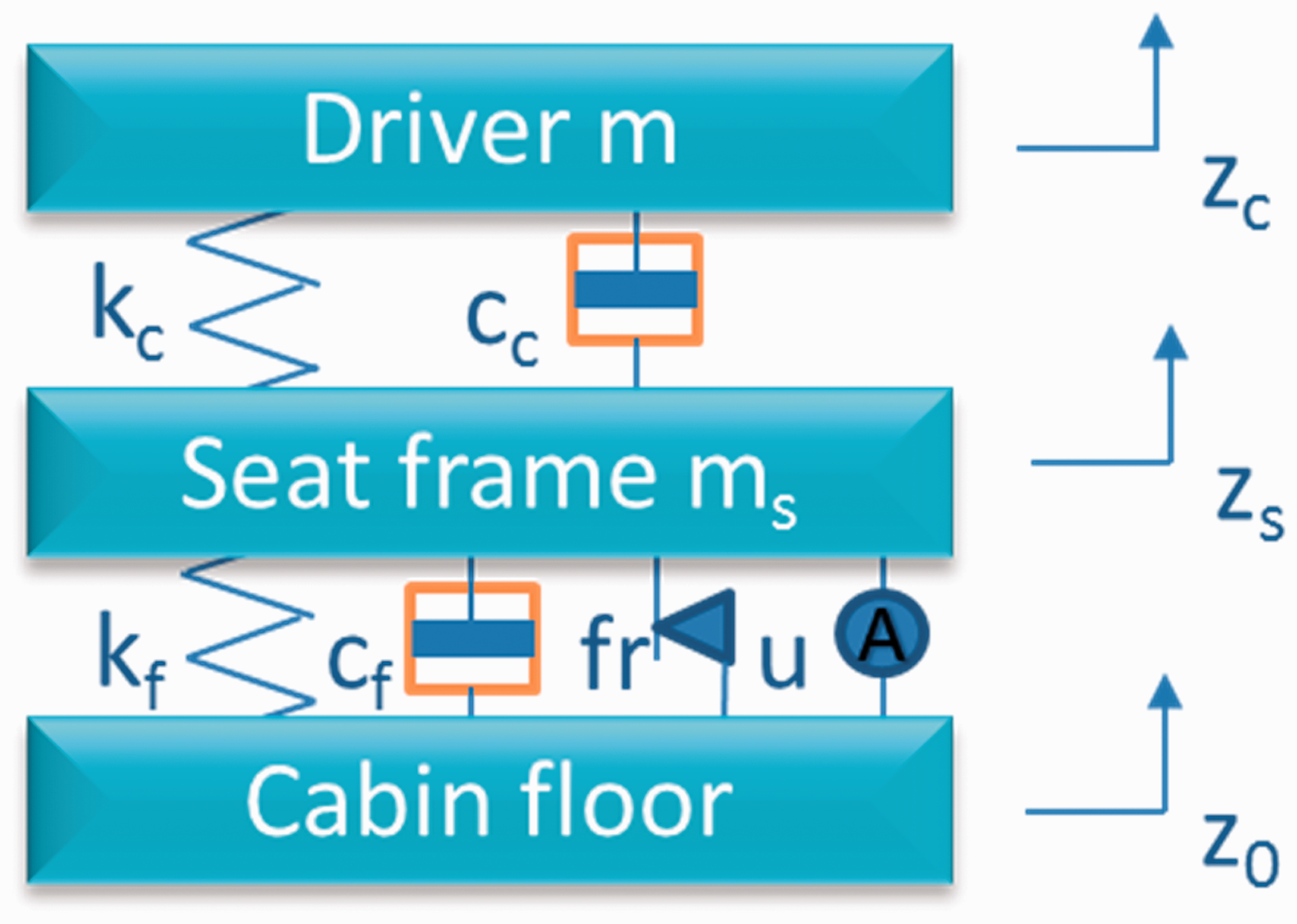


As relative displacement between the suspension base and the seat-top platform can be easily measured, and the relative velocity can also be calculated based on the measured relative displacement, in this paper, the seat variables are chosen as


In order to satisfy the performance requirement,

Because the friction force fr can be approximately estimated as

The friction estimation error is defined as

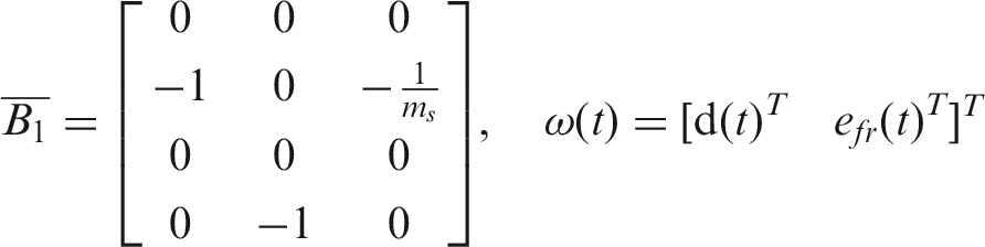
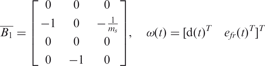
The L2 gain of the system (12) and (9) is defined as

where
A Lyapunov function is defined for the system in equation (12) as

where P is a positive definite matrix. Differentiating equation (14) yields

Adding

If we consider that

By Schur complement, 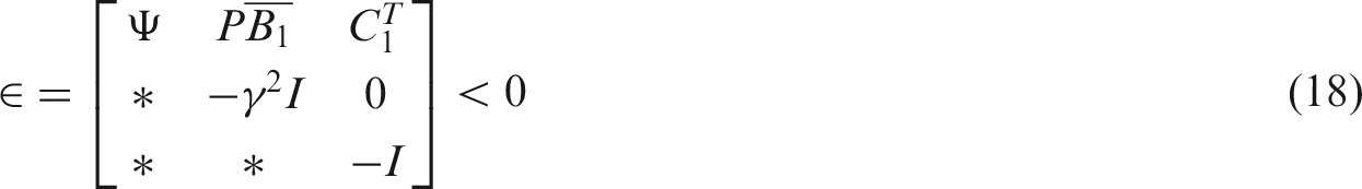
Pre- and post-multiplying equation (18) by diag(
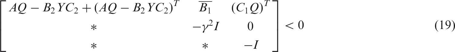
The definition

To convert equation (20) into an LMI condition, the following inequality is introduced


A static output feedback controller can be obtained by solving a minimization problem

Parameters for the seat suspension model.

Friction estimation
In the practical experiment, when the friction force is estimated by Coulomb frication model as 
Evaluation
Numerical simulation evaluation
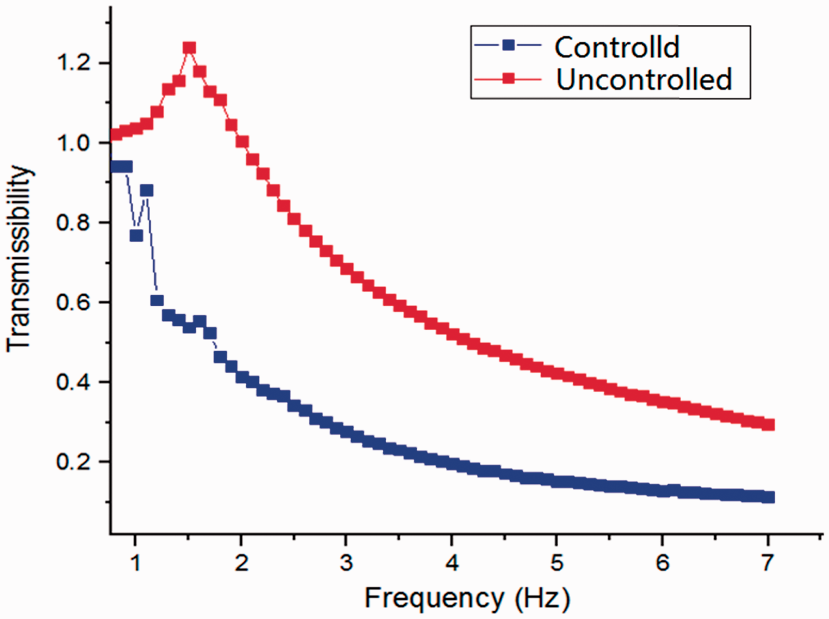
Numerical simulations were performed to show the effectiveness of the proposed control algorithm with friction compensation. Figure 9 shows the acceleration transmissibility of vibration from the seat bottom to the driver’s body. It is seen from Figure 9 that the vibration can be effectively controlled by this controller over a wide frequency range. Random vibration was also applied to test the seat suspension, in which the driver’s body vibration has been substantially reduced as shown in Figure 10. The analysis and comparison with practical experiments will be shown in the next subsection.
Driver body acceleration under random vibration. Acceleration transmissibility from seat bottom to driver body.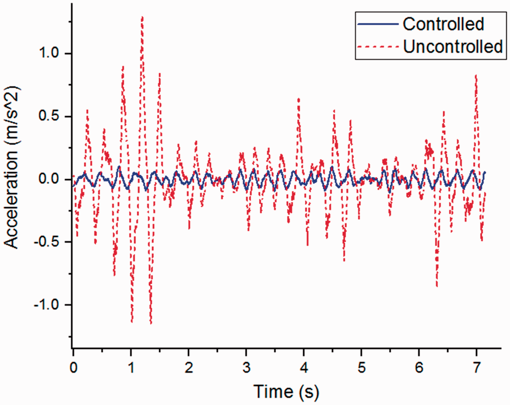
Experimental evaluation
Experimental set-up
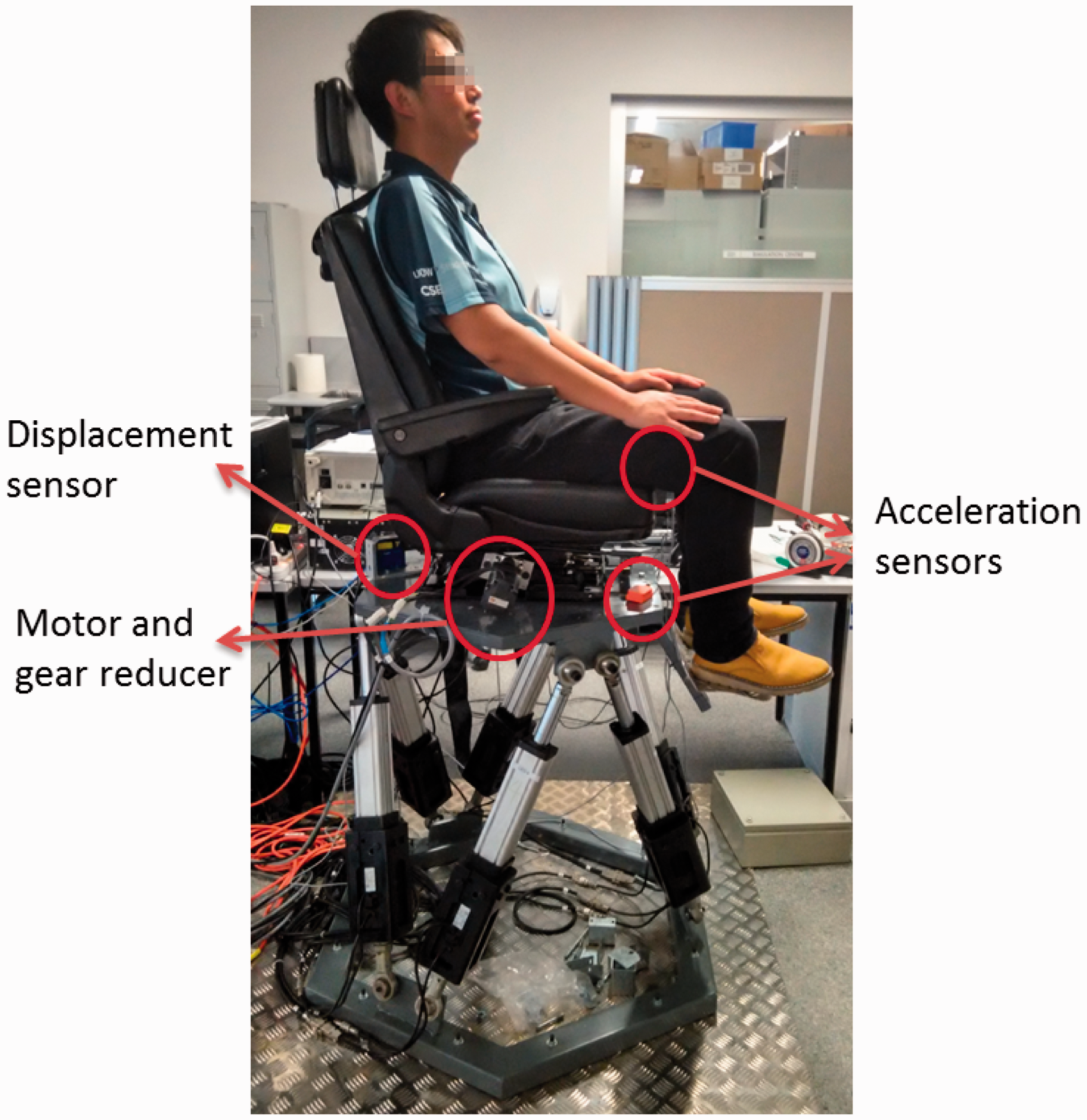
A schematic diagram of the experimental set-up is shown in Figure 11. A dSPACE ds1104 board is used to run the control algorithm and send control signals to the motor driver for controlling the active seat suspension. A laser displacement sensor (MICRO-EPSILON optoNCDT) is applied to measure the relative displacement between the suspension top platform and base. The relative displacement is differentiated in order to obtain the relative velocity in ds1104. The friction compensation-based Schematic diagram of the experimental set-up. Photo of real experimental set-up.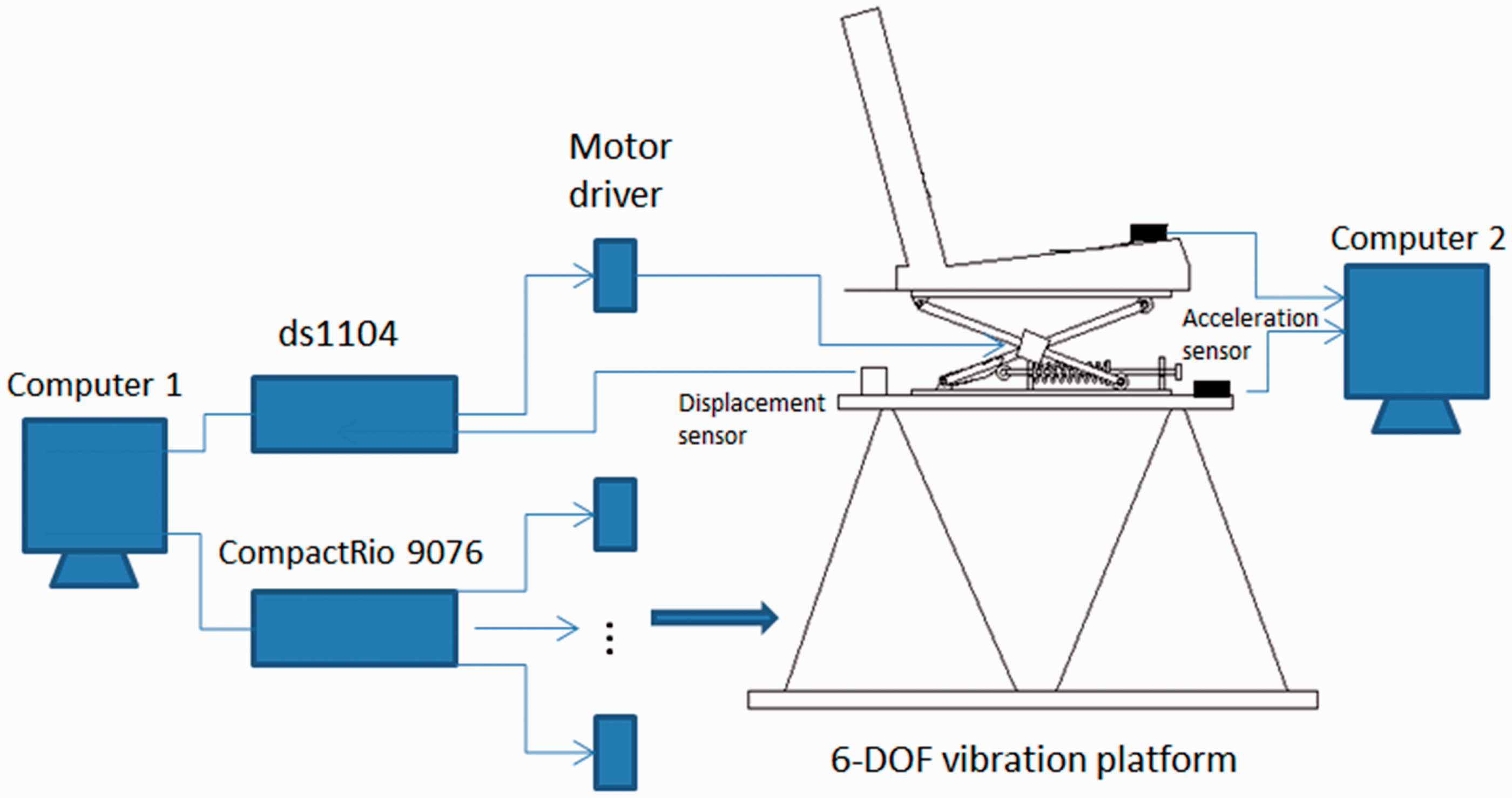
Test results
Sinusoidal excitations were applied to test this seat suspension. Different sinusoidal vibrations with amplitudes of 7, 5, 3, 2.5, 2, 1 mm, and frequencies from 1 to 7 Hz were exerted on the seat suspension, respectively. The excitation vibrations for controlled and uncontrolled seat suspension experiments had the same magnitudes. Figure 13 shows the accelerations of the driver body in the time domain without control and with control when the frequencies of the excitation vibrations were given as 3 and 4 Hz, respectively. From Figure 13, it can be seen that the peak accelerations of the driver body can be obviously reduced, which means that much less high level acceleration is transmitted to the driver’s body.
Accelerations of the seat suspension.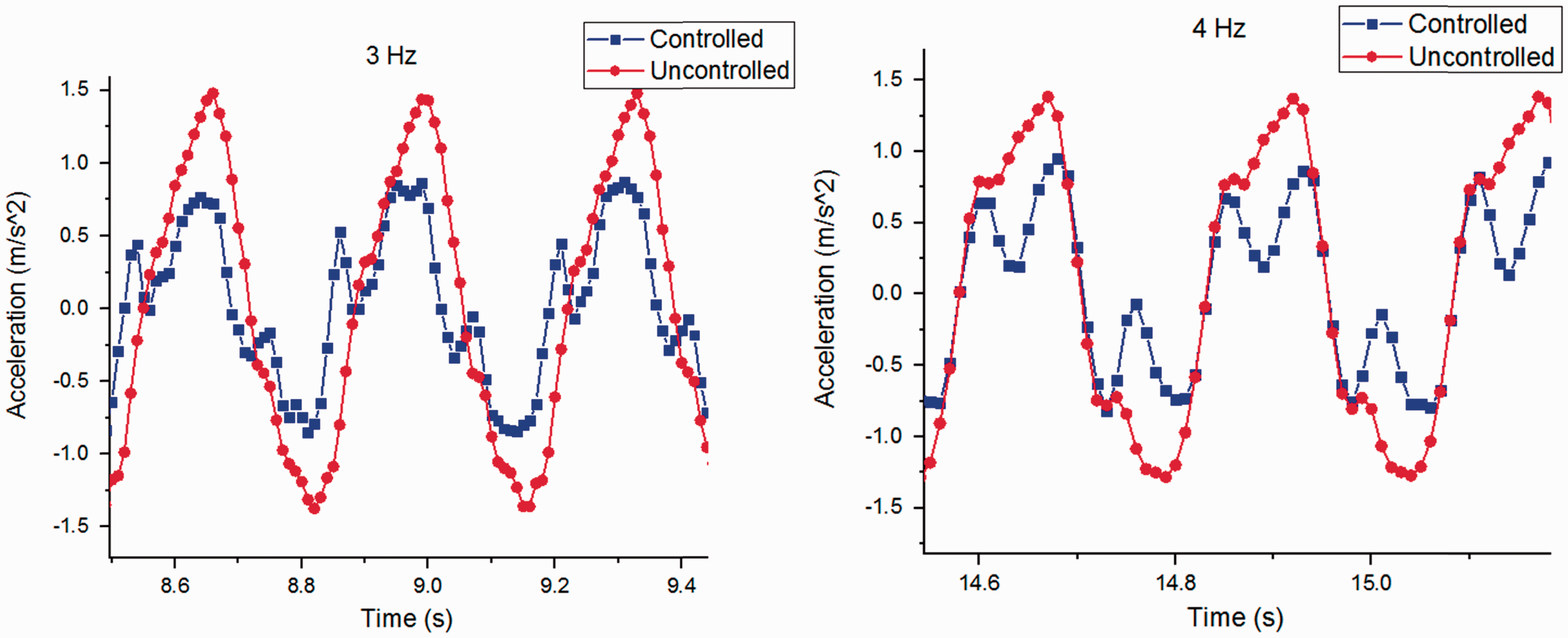
Figure 14 shows the motor torque outputs. The maximum torque was around 0.3 N/m which was amplified to 12 N/m by the gear reducer. The results show that a low power motor can be used as the suspension actuator.
Motor torque outputs.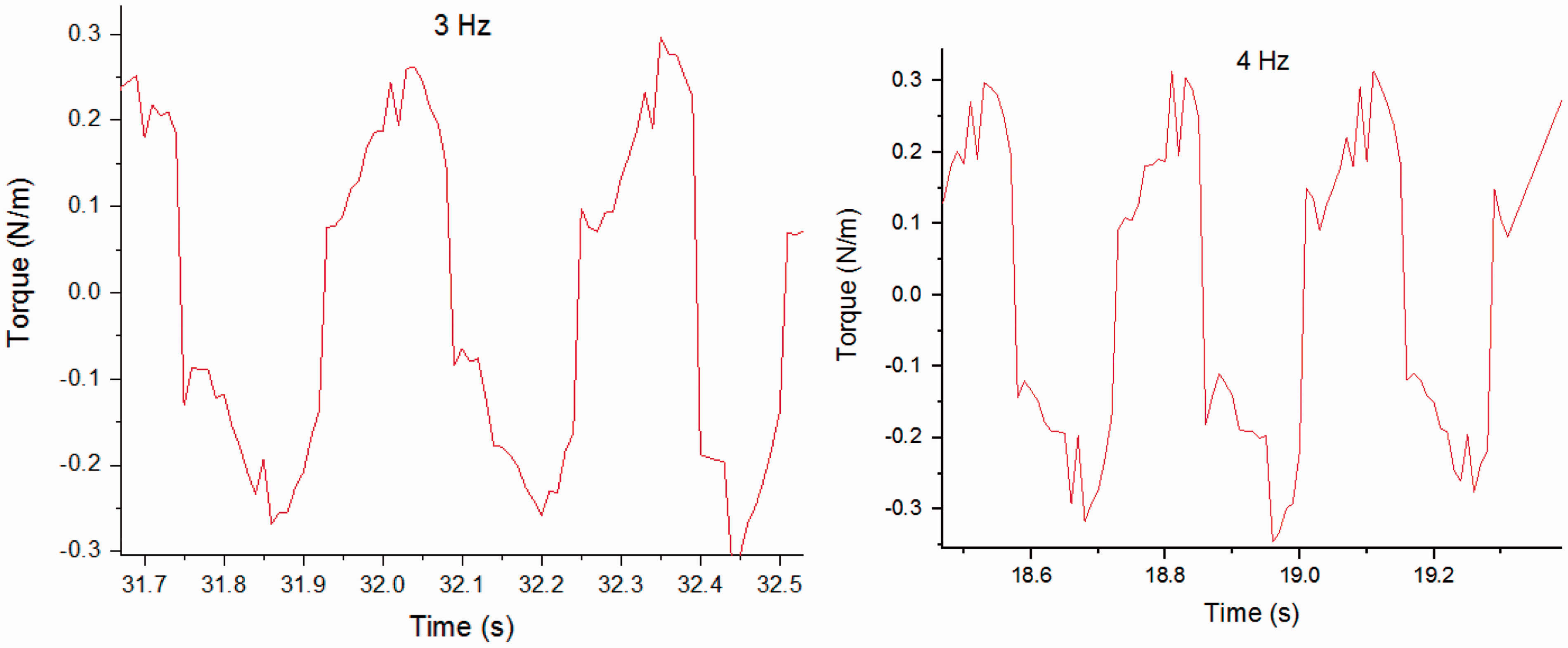
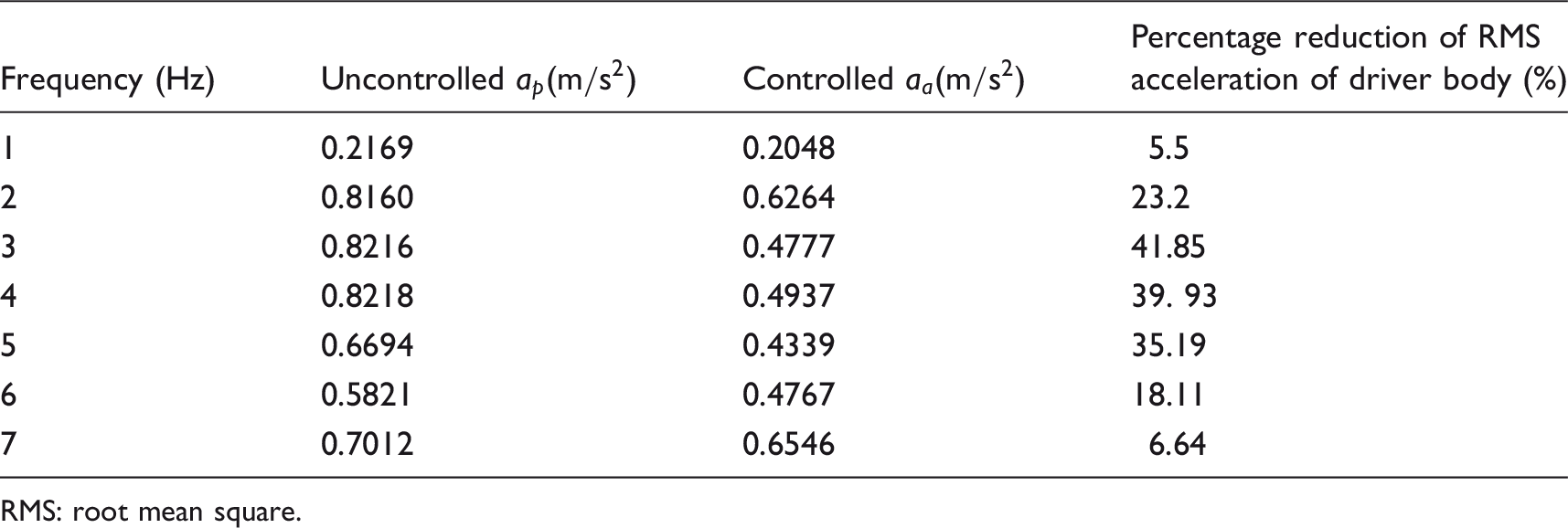
For further analysis of the suspension performance, the root mean square (RMS) is used to evaluate the measured accelerations. The RMS is defined as Acceleration transmissibility from seat bottom to driver body. RMS of accelerations under different frequencies. RMS: root mean square.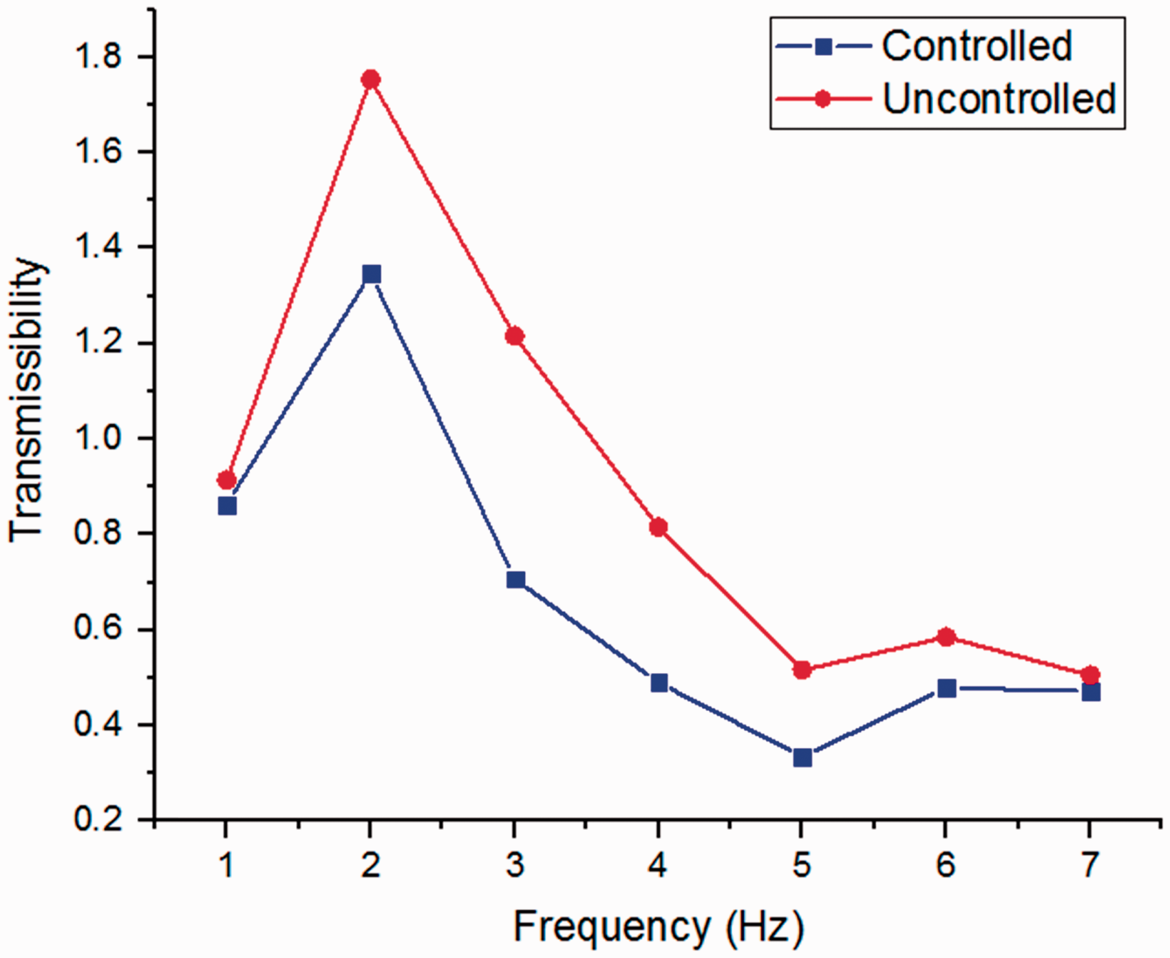
To further validate the effectiveness of the proposed suspension, a random road profile was applied to test the suspension’s performance. Figure 16 shows the accelerations of controlled and uncontrolled seat, from where similar conclusion can be drawn that the proposed active suspension and controller are effective in improving suspension performance.
Random vibration test.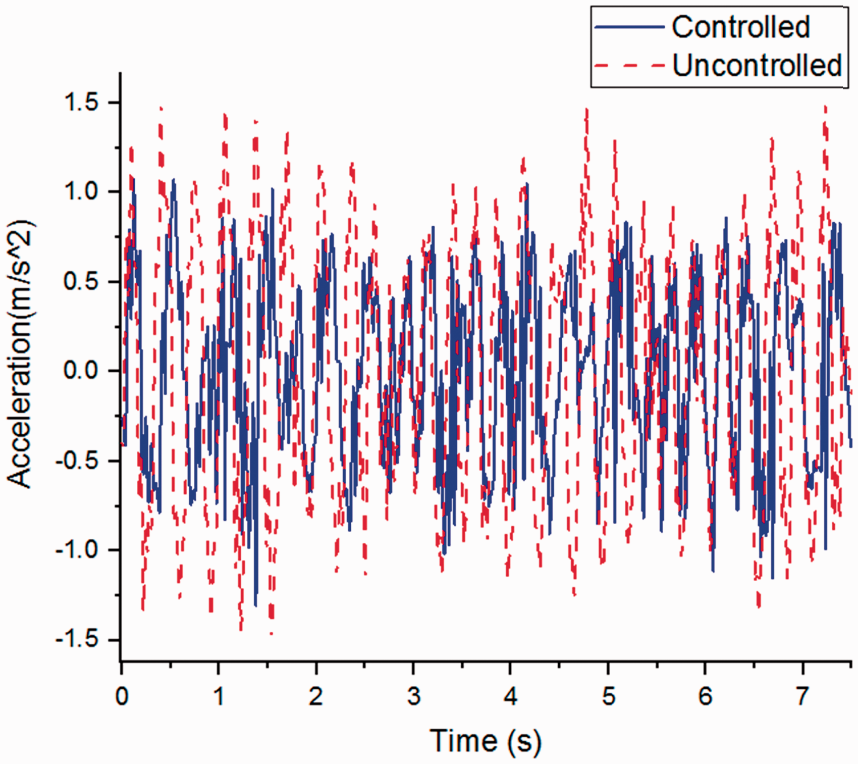
In this work, the parameters defined in ISO 2631-1 were used to evaluate the human body exposure to vibration on the basis of time history of the frequency-weighted acceleration (aw) and the fourth power vibration dose value (VDV). The seat effective amplitude transmissibility (SEAT) and VDV ratio are obtained as follows

Random vibration control performance.
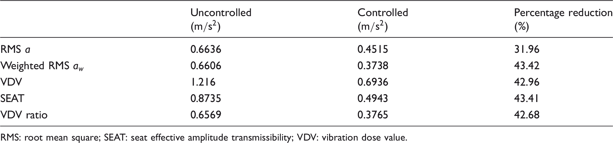
RMS: root mean square; SEAT: seat effective amplitude transmissibility; VDV: vibration dose value.
The energy consumption is an important issue for practical applications of an active seat suspension. The theoretical power of this active seat suspension in a random vibration test can be defined as The power of active seat suspension in random vibration test.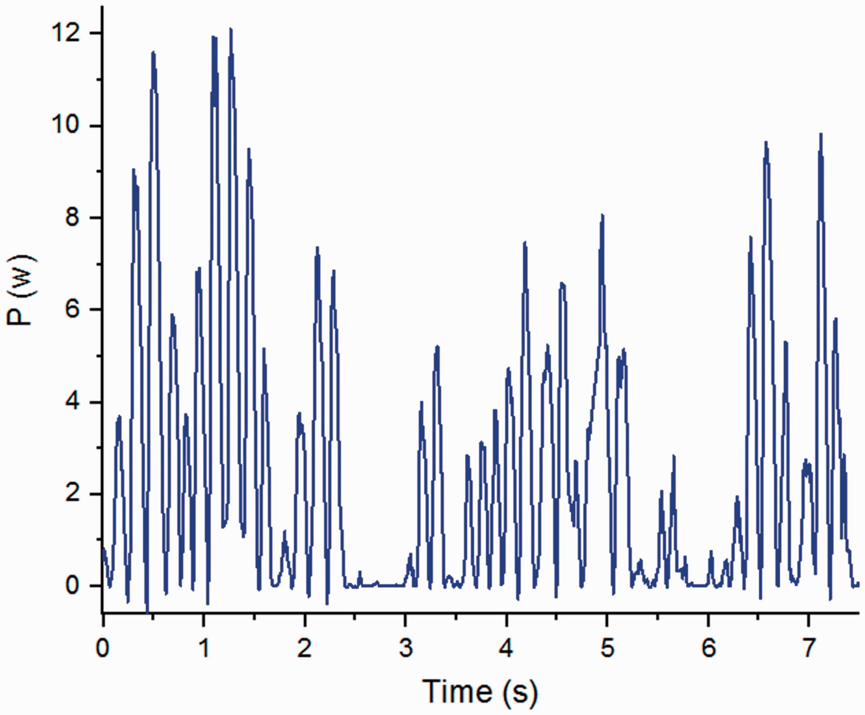
Comparison between simulation results and experimental results
Both simulation results and experimental results indicate the effectiveness of the designed active seat suspension and the proposed control algorithm. The differences between simulation and experimental results mainly come from the inaccuracy of the friction model. A hysteresis viscous friction model has been applied in the simulation which can accurately describe the kinetic friction. However, the stick–slip phenomena caused by the static friction cannot be described by the adopted friction model. In the real experiments, the stick–slip phenomenon occurs when the seat suspension works in low frequency excitation.
Conclusions
In order to improve the ride comfort for drivers of heavy-duty vehicles, an innovative active suspension system has been proposed. A rotary motor is applied as the actuator and its torque output is amplified by a gear reducer. A low rated power motor can be used for this active suspension and this can reduce the cost of the suspension set-up. This rotary motor is installed in the scissor structure centre of a passive suspension. Unlike most designs proposed in the existing literature, this active suspension uses torque output directly rather than force output. The suspension parameters are identified by force–displacement response tests, where the friction force is found to be a main part of the disturbance. A static output feedback
Footnotes
Acknowledgement
The authors wish to gratefully acknowledge the help of Dr Madeleine Strong Cincotta in the final language editing of this paper.
Declaration of conflicting interests
The author(s) declared no potential conflicts of interest with respect to the research, authorship, and/or publication of this article.
Funding
The author(s) disclosed receipt of the following financial support for the research, authorship, and/or publication of this article: This research was supported under University of Wollongong Global Challenge Project and the Open Research Fund Program of the State Key Laboratory of Advanced Design and Manufacturing for Vehicle Body, Hunan University (31515001) and China Scholarship Council joint scholarships.