
Abstract
Off-road mobile machine operators are exposed to whole-body vibration (WBV) which can result in adverse health effects. Seat suspensions are used to reduce WBV exposure, but typical passive seats cannot attenuate frequencies below 1.13 Hz. The proposed device is designed to minimize transmissibility from 0 to 20 Hz because this bandwidth contains the dominant frequency for most off-road vehicles. The semi-active smart device uses bang-bang control and is designed to be installed in place of the seat-pan cushion in OEM passive seats. Modelled as a two degree of freedom system, simulations were performed using a lumped mass model (ωn = 3 Hz; sinusoidal base excitation 0-20 Hz). Using a hexapod robot, a prototype reduced transmissibility compared to a passive OEM seat. The device was up to 5 times more effective than a passive seat in reducing vibration transmissibility. Simulations revealed that operator mass and seat stiffness variations have little effect on device WBV attenuation performance.
Keywords
Introduction
Whole-body vibration (WBV) has been well researched for its deleterious effects on operators of off-road mobile equipment.1–3 Operators of heavy equipment are exposed to high magnitudes of WBV at frequencies which cause discomfort and are associated with a number of adverse health effects such as motor impairment and musculoskeletal injury.3–6 The frequency range associated with WBV is 0.5 Hz to 80 Hz, 7 although WBV perception is dependent on the acceleration magnitude and axis. 8 Vibration perception in the vertical axis is highest between 5 and 10 Hz. 8 For most off-road vehicles, the dominant WBV frequencies are below 20 Hz. 2
The vibration level that is felt by the operator is not the same level of vibration measured at the seat frame due to the transmissibility of the seat cushion.
7
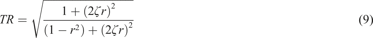
Transmissibility, TR is defined as the ratio of the output vibration (cushion) to input vibration (vehicle).

Values for transmissibility greater than 1 mean that input vibration is being amplified whereas values less than 1 imply that vibration input is being attenuated. For a vehicle seat, attenuation of vibration across the entire spectrum for a random input is desirable. However, with a passive seat suspension this is unattainable.
To reduce the magnitude of vibration felt by the operator, the simplest solution is to install a suspension seat. Cab suspensions and axle suspensions, which also reduce vibration, are not uncommon in tractors. 9 However, off-road heavy equipment used in agriculture does not experience a fixed excitation frequency but rather a range of frequencies. Normally, the spring rate is selected based on the dominant frequency. The dominant frequency is influenced by the environment (i.e., road surface and speed), 10 but is also influenced by the type of vehicle, tires and suspension.11–13 Passive seat suspensions rely on fixed stiffness and damping to reduce force transmission to the seated operator.
Boileau and Rakheja
14
observed a dominant frequency of 2.5 Hz in the z-axis (vertical), while more recent research has indicated a value closer to 2 Hz for log skidding machines.
15
A lower dominant frequency requires a seat with lower stiffness to further reduce transmissibility, which is difficult to achieve in practice as it requires the operator to tune the seat stiffness for their body mass. Vibration amplification occurs at frequencies less than the cut-off frequency,
The accepted American Society of Agricultural and Biological Engineers (ASABE) guideline for operator seats in agricultural equipment suggests there is a lower cut-off frequency limit of 0.8 Hz for the natural frequency of typical seat suspensions due, in part, to the physical limitations of mechanical linkages and steel springs. 16 Thus, attenuation of frequencies of 1.13 Hz or less is unattainable with typical passive seat suspensions. Another important component of the seating system which affects operator comfort and WBV transmission is the seat cushion. Seat cushion selection is a complex design problem that must balance ergonomics and vehicle dynamics. 17 Selection of a material that is soft enough to provide a comfortable pressure distribution across the gluteal musculature can prove to have poor dynamic characteristics at low frequencies. 16 These issues are introduced by the need to tune the seat stiffness to the operator body mass in order to maintain a consistent resonant frequency of the suspension.16,18,19
Active systems are widely used in vibration control of machinery,20,21 buildings22,23 and vehicles24–27 and they have been researched in recent years using a variety of control methods. Most notably, work is being conducted in the automotive sector for vehicle suspension systems. 25 For operator seats, a pneumatic system of active damping was shown to have improved performance when a negative stiffness structure was added. 26 Negative stiffness occurs when the applied force and displacement are opposite in direction. 28 Active seat suspensions require an actuator that is powerful enough to move the operator mass, however, active systems can be sensitive to changes in occupant mass and are not robust enough for off-road use. Maciejewski et al. 24 examined the robustness of an active system with a changing operator mass by using a lumped mass model to help eliminate the variability between physical testing with real operators. Their simulation and experimental results showed more robust behaviour by the active system at frequencies below 4 Hz, while the active and passive systems exhibited more similar behaviours above 4 Hz. 24 This suggests that the active system is more robust than the passive system and thus would be more effective across the range of operator masses encountered by seat suspensions at input frequencies below 4 Hz when compared to the passive system. 24
Another means to reduce WBV transmission to the operator are semi-active suspension systems. These systems attenuate vibration by reacting to the input vibration and modifying either system stiffness or damping properties. Semi-active systems, unlike active systems, cannot produce any external actuation force but can provide a means to adjust the dynamic characteristics such as stiffness and damping. Semi-active seating systems have been developed for operator seat suspensions but again these systems typically involve replacement of the entire operator seat. Lastly, semi-active systems tend to be lower cost than active systems.
Both active and semi-active systems require a control system to modify the parameters and react to the vibration. A control system is needed to determine the amount of restoring force to apply in an active system, and to modify the stiffness or damping in a semi-active system. The most common and simplest control strategy for either system is a bang-bang control. Various bang-bang control laws for damping configurations of semi-active suspension systems have been investigated and demonstrated with simulations. Moosheimer and Waller 29 proposed three control laws that showed significant displacement reductions. Often the cushion of the seat is designed for specific stiffness and damping values, but this cushion has not been incorporated into a smart system. It is proposed that the cushion on original equipment manufacturer (OEM) passive mechanical seat suspensions could be replaced by a smart device to allow improved vibration reduction as compared to an OEM seat.
Recent research of active and semi-active designs has focused on the suspension components between the mounting surface of the vehicle and the operator cushion. Seat suspension designers exclude the seat cushion in their designs under the assumption that the cushion is much stiffer than the seat suspension components, thus offering little attenuation benefit compared to the major suspension components.
The proposed device uses the space that is normally occupied by the cushion as a location to install a semi-active suspension device for WBV attenuation. Such an approach is novel and has never been proposed before. The device uses a controlled damper to improve WBV attenuation. This device could be implemented for all types of off-road vehicles which would improve ride comfort and reduce injury risk. The cost of replacing an entire seat in a vehicle can be high and modifications to the mounting location may be required to accommodate a newer WBV reducing seat. Using the proposed device, the installation of a semi-active suspension into older vehicles would be greatly simplified in terms of effort and cost. A simplified mathematical model for this device is presented and discussed. A prototype was built and tested on a low-cost passive suspension tractor seat. The purpose of this paper is to explore the effectiveness of replacing the cushion of an OEM operator seat with a semi-active device while leaving the existing suspension system of the seat unmodified.
Methods
Proposed device
Designed to replace the existing OEM cushion, the device would attenuate vibrations across the whole frequency range, but especially at lower frequencies ( Schematic of the proposed semi-active device.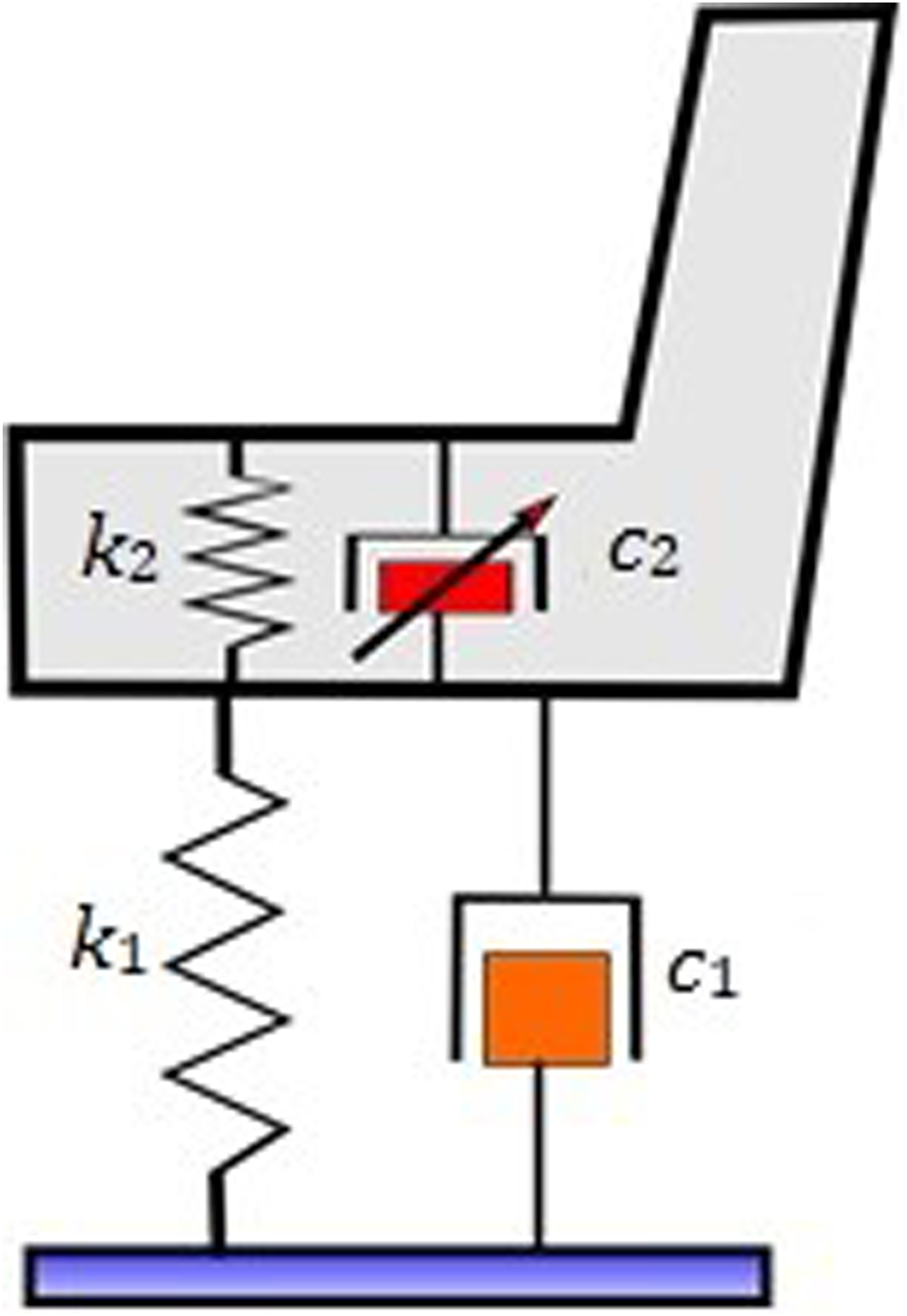
The spring stiffness and the damping of the seat are defined by k1 and c1 while the cushion stiffness and damping are k2 and c2. Acceleration or operator displacement would be measured at the mounting face (seat pan) and the Seat-Operator Interface (SOI) of the device. This would allow the semi-active system to modify the damping properties of the device based on the input using a simple control strategy. The device would be designed into the form factor of an OEM cushion, which is normally a removable and replaceable component.
Model
The suspension can be simplified into the 2-DOF system shown in Figure 2. The base is the frame of the vehicle or the floor of the cab (for vehicles with suspension systems fitted to the cab) and the motion of the base is defined by x
g
. Vibration attenuation system with two degrees of freedom and base excitation.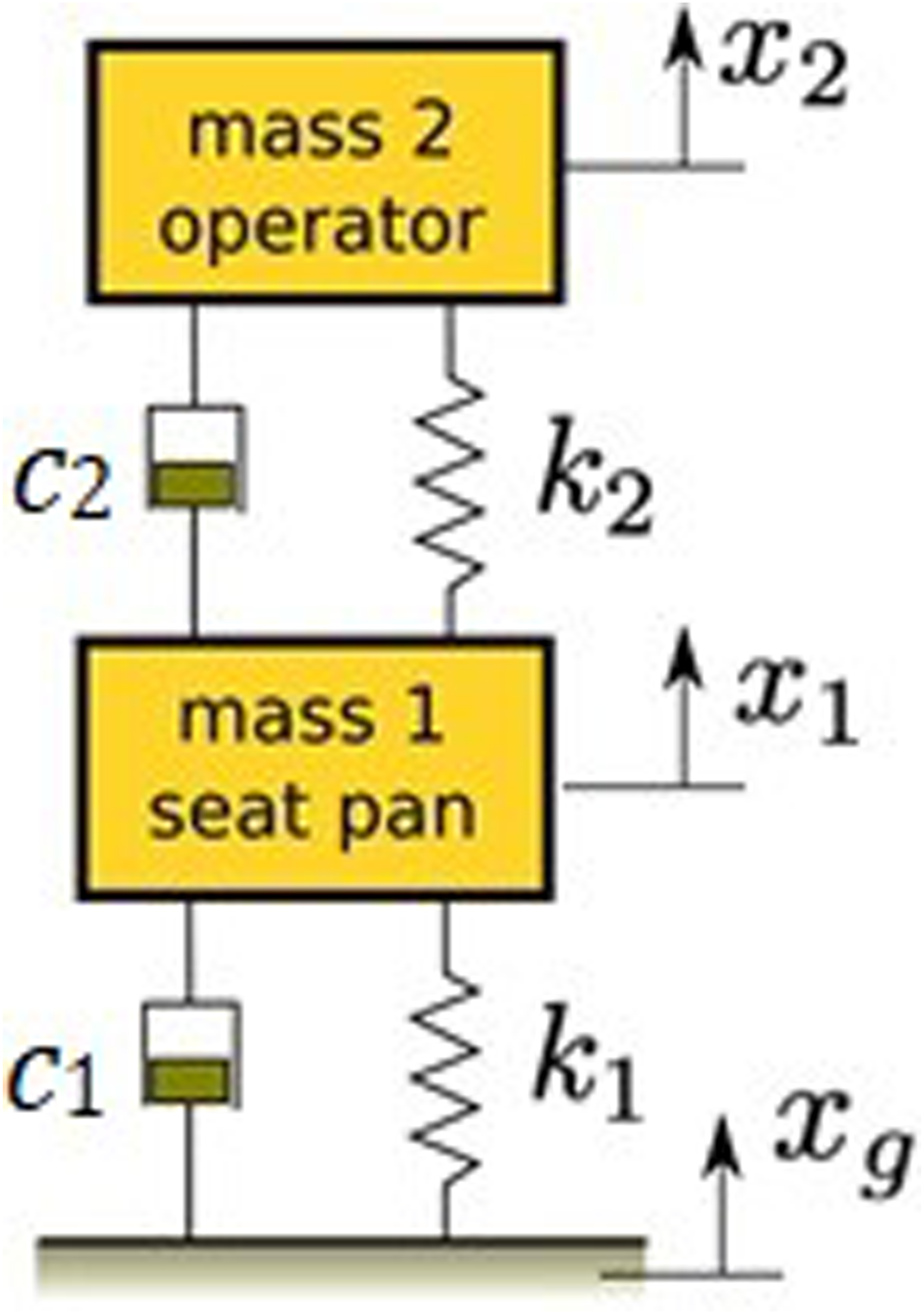
Similar modelling techniques are utilized in the simulations of the seismic response of buildings. The resulting equation of motion for base excitation for two degrees of freedom can be simplified to the following

The matrices of the system shown in Figure 2 are as follows


Solving this system to determine the natural frequencies and the mode shapes can be completed by finding the eigenvalues and eigenvectors.

The solution to the above equation yields the natural frequencies and mode shapes [ω2], [Φ], respectively.
For simulation, the entire system will undergo a simple sinusoidal base excitation over a frequency range of 0 to 20 Hz. Damper
The operating principle of the device is similar to a tuned mass damper (TMD). The addition of a secondary mass and spring to a SDOF system greatly reduces the displacement of the original mass at the desired frequency. The operating frequency of the system in most industrial applications (i.e., pumps, machine tools and motors) is fixed and therefore a TMD can be designed such that machine vibrations under operating conditions are cancelled out. For a conventional TMD, the absorber mass is usually smaller than the mass of the original system for operating constraints.
The mass and stiffness for a TMD can be selected such that

where ω e is the excitation frequency. However, for the proposed system, Mass 2 is much larger than Mass 1. The sprung mass of a typical tractor seat without the operator may be on the order of 10–20 kg. The mass of an average operator would be on the order of 80–100 kg. In practice, the operator mass would be smaller as the legs and arms would be supported by other parts of the cab (i.e., the floor, steering wheel). An assumption for the sprung operator mass is between approximately 70% and 85% of total operator mass.16,30 The human body can be subdivided into segments which possess an individual mass and stiffness in order to better represent their effects on seat response. Various models for the human body and seat system have been developed19,31 to help compare seat performance, since operator mass can affect experimental results. Moreover, the same operator may not experience similar results during multiple tests, therefore, quantifying seat system variability is challenging. Mathematical models of the human body are limited in their ability to represent the effects of vibration exposure as they are limited to segments of the body with larger masses (i.e., trunk, thighs, and head) as smaller and suspended masses (i.e., eyeballs, brain, and heart) are often difficult or impossible to model. 31 It should be noted that the models of larger mass segments are still simplifications of complex continuous systems of flesh and joints. For simplification, the inertia of the operator can be represented by a lumped mass.
For a vehicle, the system is often subjected to a broad-band excitation spectrum rather than a fixed frequency. The vehicle dynamic system will act as a filter and the resulting base excitation spectrum of the seat can be described with the highest peak considered to be the dominant frequency. This frequency is dependent on the mass of the vehicle, the type of running gear (i.e., tires or tracks) and the terrain. For the proposed device, the goal was to minimize transmissibility over the frequency range of 0 to 20 Hz because this is where the dominant frequency occurs in most off-road vehicles. 2
Variables
The OEM seat used to develop a prototype device was a low cost, compact tractor seat that featured a 15 cm suspension travel, as well as an adjustment for ride height and operator mass. The seat had a fixed spring rate with an adjustable pre-load for operator mass ranging from 50 kg to 120 kg and a fixed damping rate.
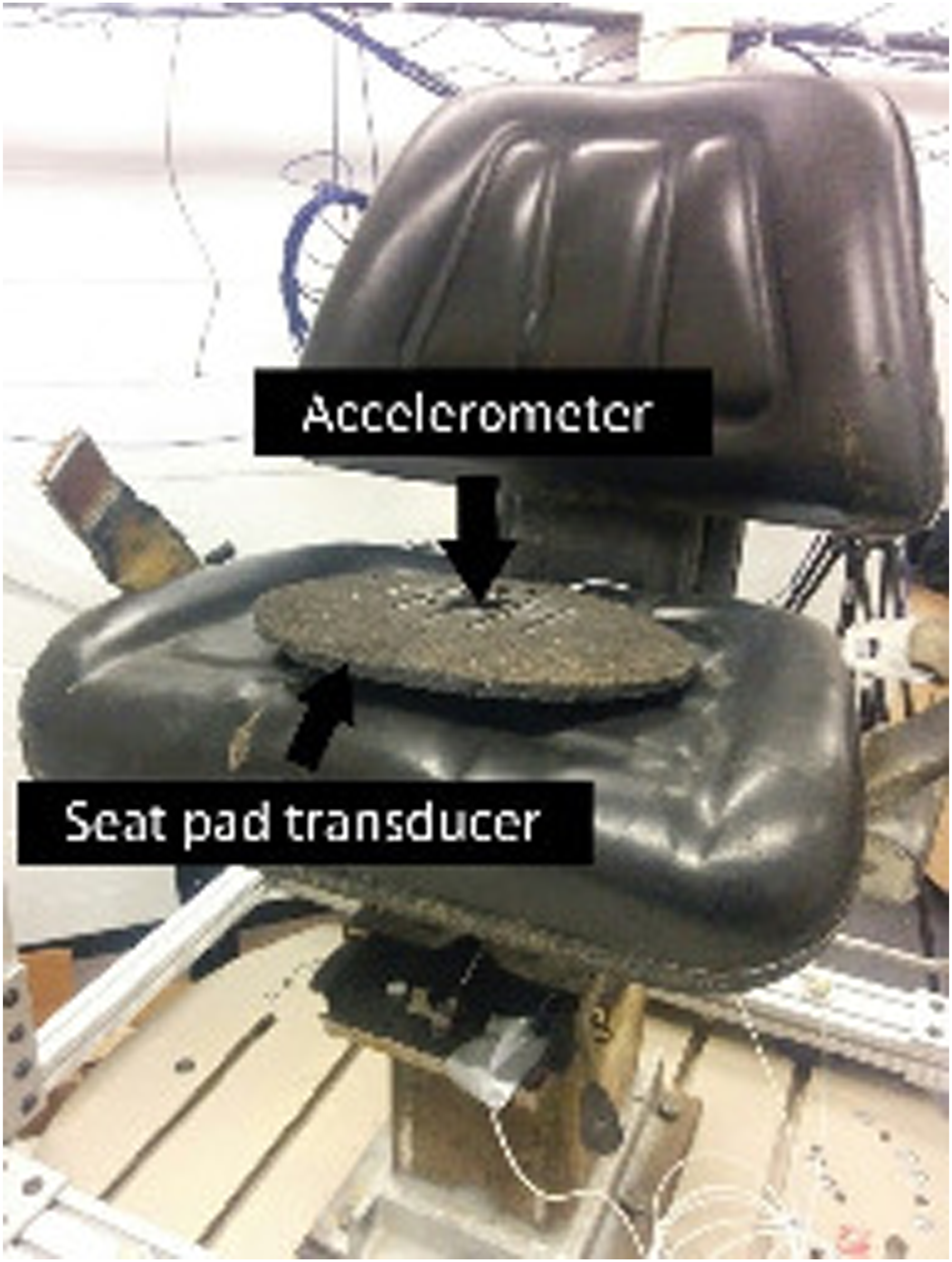
Seat stiffness parameters were determined by mounting a seat on a 6-DOF hexapod robot (Mikrolar, Hampton, NH, USA), which provided base excitation in the z-axis (vertical). Motion was limited to 5 mm peak to peak sinusoidal excitation due to limitations imposed by the capabilities of the hexapod robot. Base excitation and seat acceleration were measured with accelerometers positioned on the base of the seat mount under the seat cushion and on the travelling portion of the seat suspension, respectively (Figure 3). Lastly, operator acceleration was measured using an accelerometer positioned in a rubber pad placed on top of the seat pan cushion as per ISO 2631-1 (Figure 4).
7
All accelerometers were ceramic shear ICP®, PCB model 33B40 uniaxial accelerometers (Dalimar Instruments, Vaudreuil, QC). Location of the base and seat accelerometers. Seat pad transducer sitting on the OEM seat and cushion (Darby Manufacturing T300 Tractor Seat).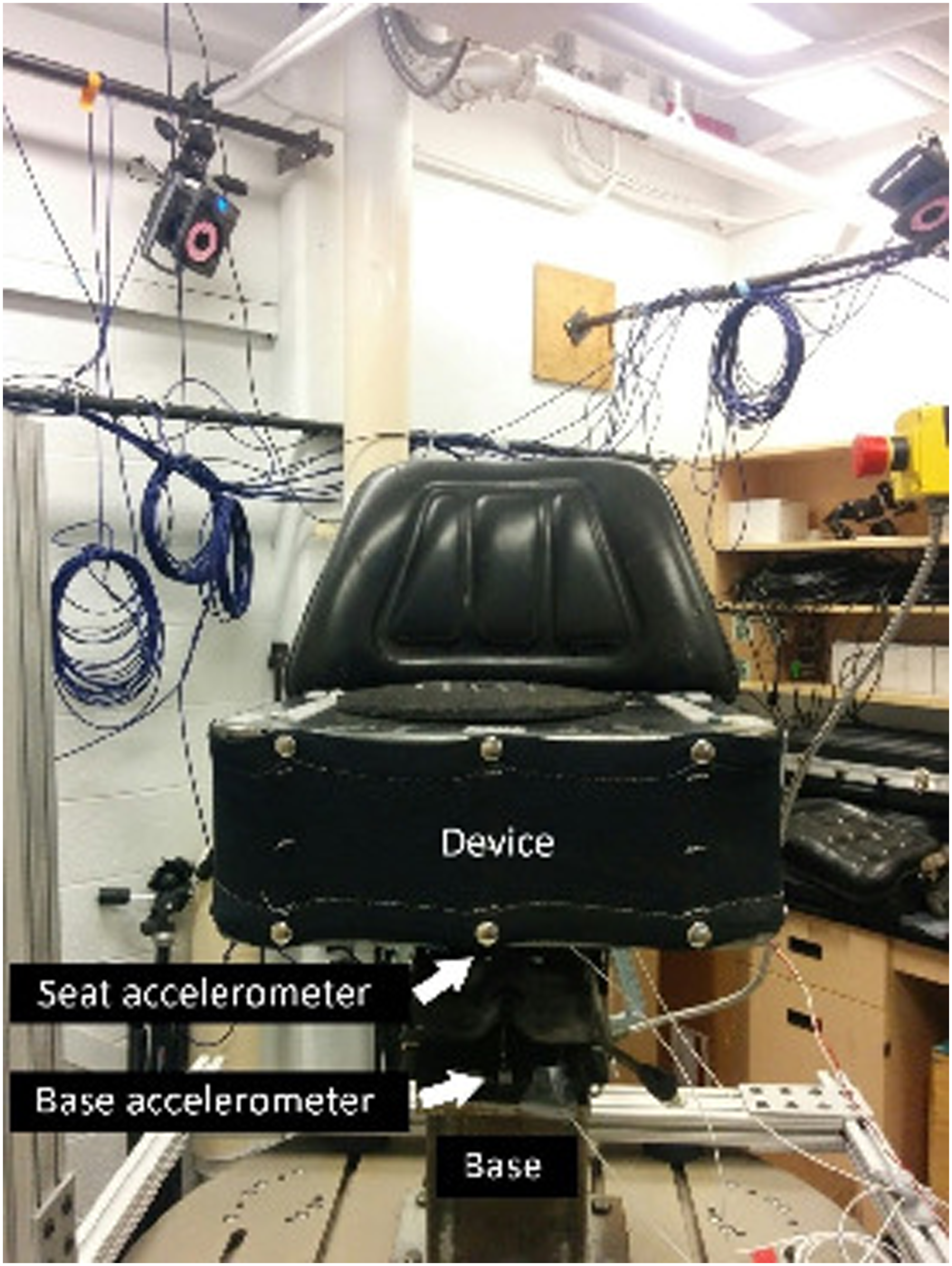
The accelerometers were connected to a National Instruments USB (DAQ model 6341, National Instruments Corp, Austin, TX, USA) and data were collected at 1000 Hz. The accelerometers had a frequency range of 0.5 Hz to 3000 Hz when factory calibrated per ISO 16,063-21. 32 A sine sweep with displacement amplitude of 2.5 mm was performed from 1 to 4.8 Hz, with a step size of 0.5 Hz from 1 to 2 Hz and a step size of 0.191 Hz from 2 to 4.7 Hz (Table A1). Following data collection, a Type II Chebyshev filter with a 5 Hz pass band and a 25 Hz stop band was applied.
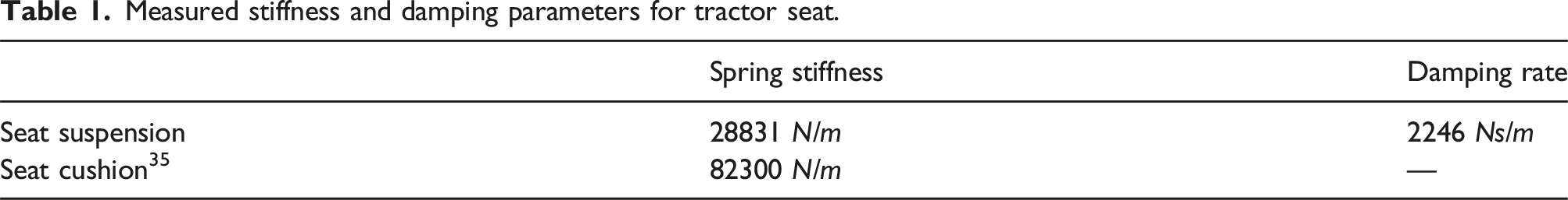
Determination of the spring rate and the damping of the seat suspension was conducted by removing the cushion to isolate the spring and damper. A test mass of 66.6 kg was used to identify the natural frequency using a sine sweep test. This test mass corresponded to an operator mass of approximately 80 kg when considering the parts of the human body that are not supported by the seat or steering wheel. The frequency response function (FRF) plot is shown in (Figure 5) and the parameters are summarized in Table 1. Transmissibility for seat suspension (SDOF) with 66.6 kg mass under sine sweep excitation. Measured stiffness and damping parameters for tractor seat.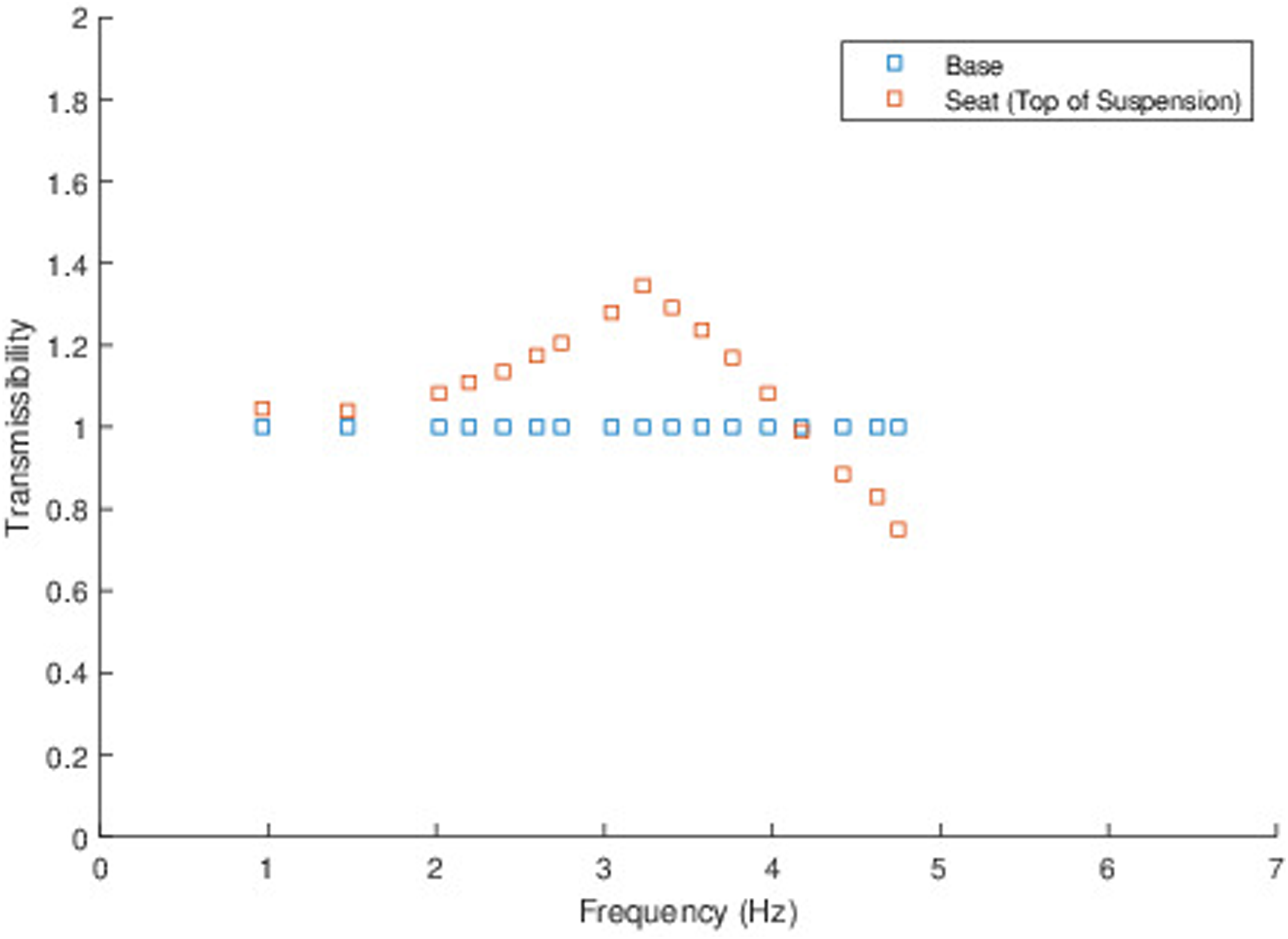
Determination of
The damping coefficient was estimated by solving for the damping ratio using the transmissibility ratio under base excitation.
33
Seat cushion properties could not be measured using a similar method because the hexapod robot could not achieve high enough frequencies to determine the natural frequency of the cushion with the test mass.
Determination of cushion stiffness for existing seats can be conducted according to the method described in SAE J1051 201,308. 34 Utilizing a similar style of seat, Boileau and Rakheja 14 determined the cushion stiffness to be 47,700 N/m and 82,300 N/m, when the seat was adjusted for the preloads of 540 N and 706 N, respectively. In this work, the peak response for the cushion exceeded 10 Hz (exceeding the hexapod robot range) and as such stiffness characteristics could not be determined. A high peak excitation frequency corresponds to a stiff cushion, therefore, stiffness for the heavy pre-load provided by Boileau and Rakheja 14 was used.
Control
The model shown in Figure 2 is similar to a quarter car model where k1 and c1 are related to the stiffness and damping of a rubber tire, and
Two of the control laws provided by Moosheimer and Waller 29 were considered in this work and are based on power transferred between the masses.
Control Law 1 was insufficient for this type of system, as damping was always ‘on’ when using this law.
The power
The variable D = [0,1] can be used to represent a switch, at 0 where damping force is at its minimum
Control law 2
Control Law 2 activates the damper (D = 1) only if it removes energy from Mass 2.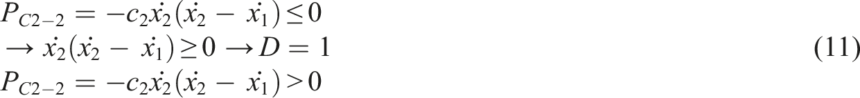

The above case is similar to that of the skyhook model presented by Yao et al. 35
Control law 3
Control law 3 activates the damper D = 1 only if it removes more energy from Mass 2 than Mass 1 and conversely, transmits less energy to Mass 2 than Mass 1.

Simulations
The lumped mass model was utilized to simulate the system dynamics where the time integration of equation (2) was carried out using the central difference method. 36
The model was solved numerically for position relative to the base. Seat and operator position must be corrected by adding the motion of the base to each in order to obtain the position, velocity, and acceleration relative to the inertial reference frame. The inertial reference frame is required in this case as the operator will be affected by the trajectory in the inertial frame. This is controlled, however, by the physical limitations of the suspension travel so the operator must accelerate with the vehicle for large movements.
Peak response at each frequency is found once the solution has reached steady state. The transmissibility ratio (TR) is then calculated by
Model comparison
The numerical solution of the model with the control strategy implemented was validated by comparing the solution to the results presented by Moosheimer et al.
29
The system presented had a mass ratio, Transmissibility of a mass spring damper system using damping coefficients 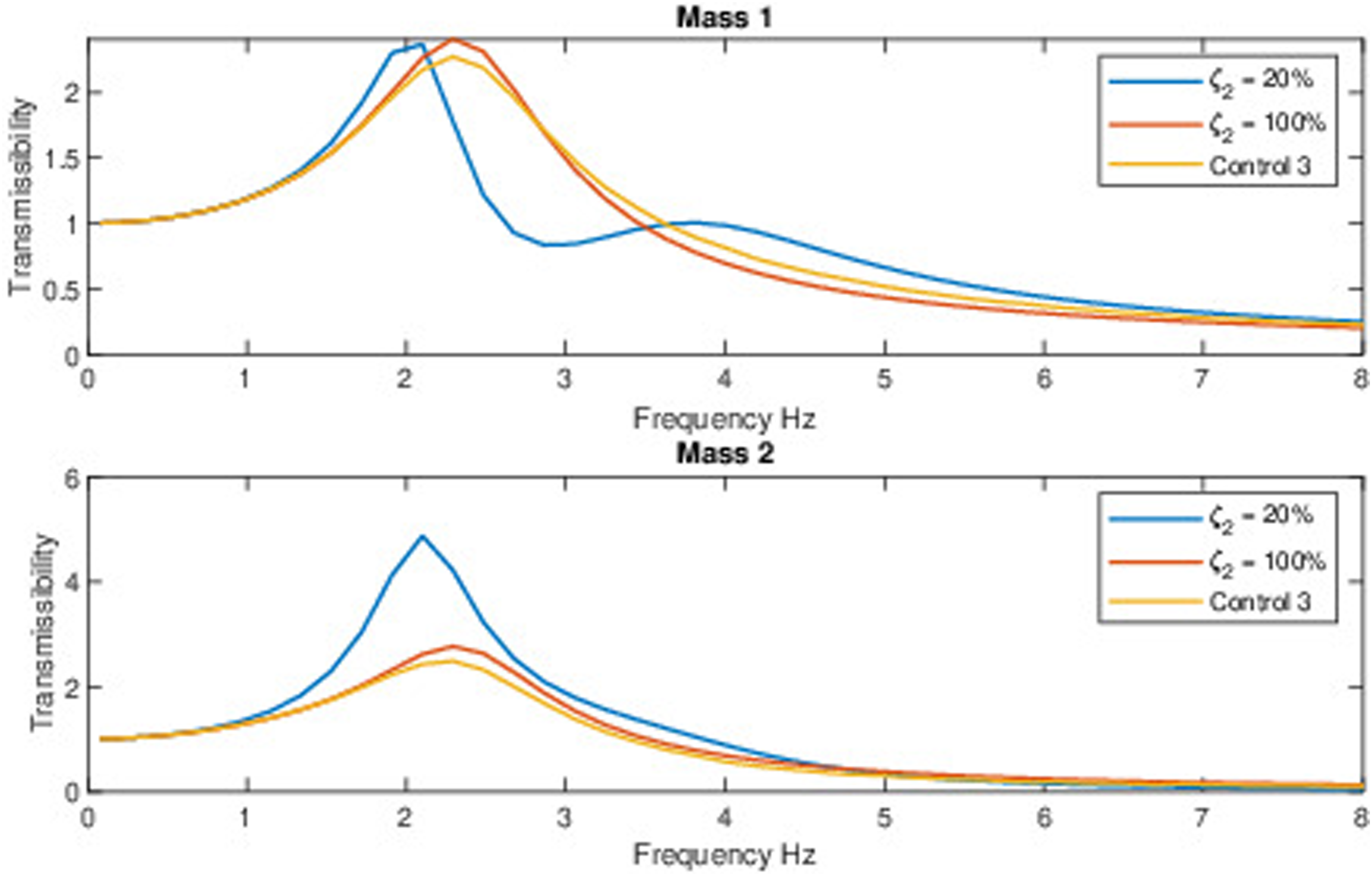
To check the numerical solution for a different set of variables, a typical TMD was simulated. This was conducted to compare the response of a typical TMD with the response of the proposed device. For a typical TMD, isolation of Mass 1 is desirable, however, for an operator suspension system like the prototype device, isolation of Mass 2 (i.e., the machine operator) is desired. The mass ratio for a typical TMD is less than unity but for the proposed device, the mass ratio will be much greater than 1.
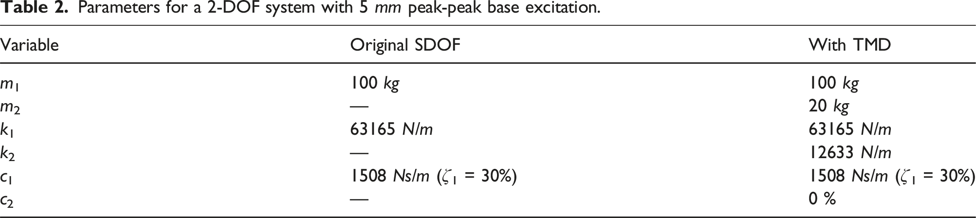
The frequency response function of the 2-DOF system presented in Figure 2 is shown in Figure 7. The stiffness and damping parameters are shown in Table 2. The base undergoes 5 mm peak to peak sinusoidal motion over the frequency range 0.08 Hz to 20 Hz. Transmissibility of (a) Mass 1 and (b) Mass 2 for a 2DOF system with base excitation. Parameters for a 2-DOF system with 5 mm peak-peak base excitation.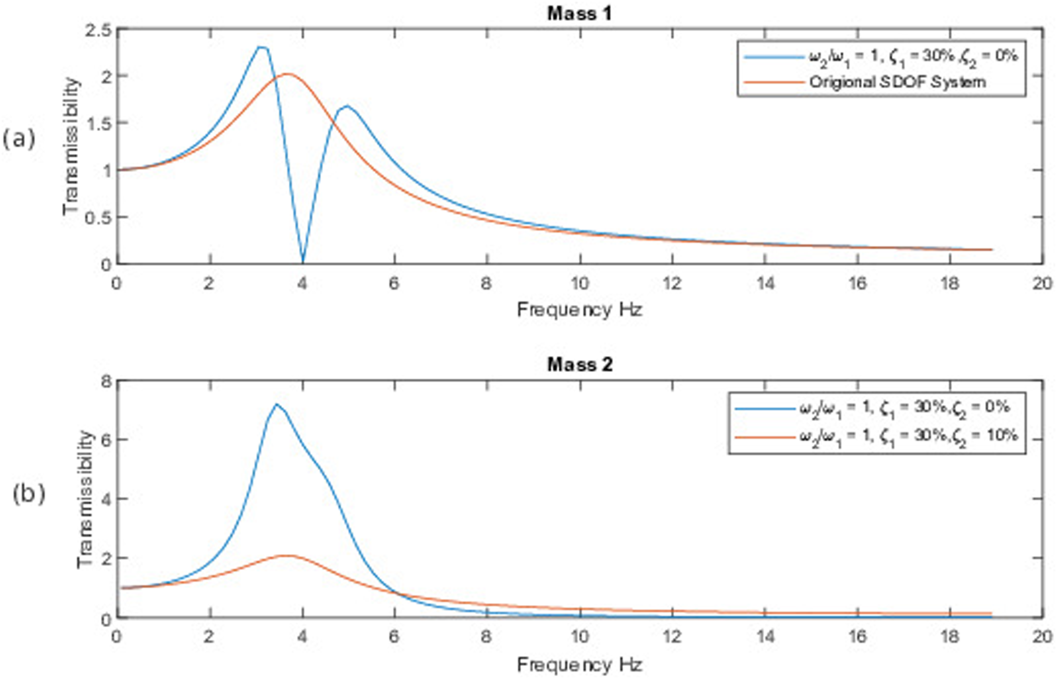
Separation of the system peaks is dependent on the mass ratio
For the response shown in Figure 7, it is clear that if the operating frequency is 4 Hz then Mass 1 is completely isolated from the base movement. Mass 2, however, is experiencing amplification 5.8 times the motion of the base. This may be acceptable for a stationary system in an industrial setting but would be ineffective for a vehicle suspension system.
Experimental setup
To validate the simulation, an OEM tractor seat (Model T300, Darby Manufacturing, Sudbury ON, Canada) was mounted onto a Mikrolar R-3000 hexapod robot (Mikrolar, Hampton, USA). During the experimental trials, C-clamps were used to immobilize all components of the seat suspension, creating a rigid system. The robot was used to provide vertical sinusoidal excitation to the seat, with a displacement amplitude of 2.5 mm (5 mm peak-to-peak). Excitation was provided from 0.5 Hz to 9 Hz. In areas of rapid change in transmissibility, a step size of 0.1 Hz was used, otherwise a step size of 0.5 Hz was used. Full details of the sinusoidal excitation are provided in Table A2.
Tri-axial accelerometers (Dalimar ceramic shear ICP® accel PCB model 356A17 tri-axial accelerometer, Dalimar Instruments. Vaudreuil, QC) were used to record acceleration data at the seat base and Mass 1, and a uniaxial accelerometer (Dalimar Modal array, ceramic shear ICP® accel PCB model 333B40 uniaxial accelerometer, Dalimar Instruments. Vaudreuil, QC) was used to record vertical acceleration data at Mass 2. Acceleration data were recorded at 1280 Hz onto a Spider 20E (Crystal Instruments Corp., Santa Clara, CA, USA), for two conditions: the OEM seat and the prototype device. The OEM seat uses the OEM tractor seat, with its original cushion. Alternatively, for the prototype device, the cushion of the OEM seat was replaced with the prototype device. A test mass of 66.6 kg (Mass (2) was used to represent an operator mass of approximately 80 kg for both experiments. MATLAB R2020a (MathWorks Inc., Natick, MA, USA) was used to band pass filter the acceleration data from 0.4 to 100 Hz.
7
These data were then used to determine displacement transmissibility in the vertical axis using equation (15). When determining acceleration transmissibility using equation (16), the acceleration data were filtered using a second order Butterworth Bandpass filter with a passband of 
Results
Generalized device stiffness results


Table of parameters for different device stiffness.
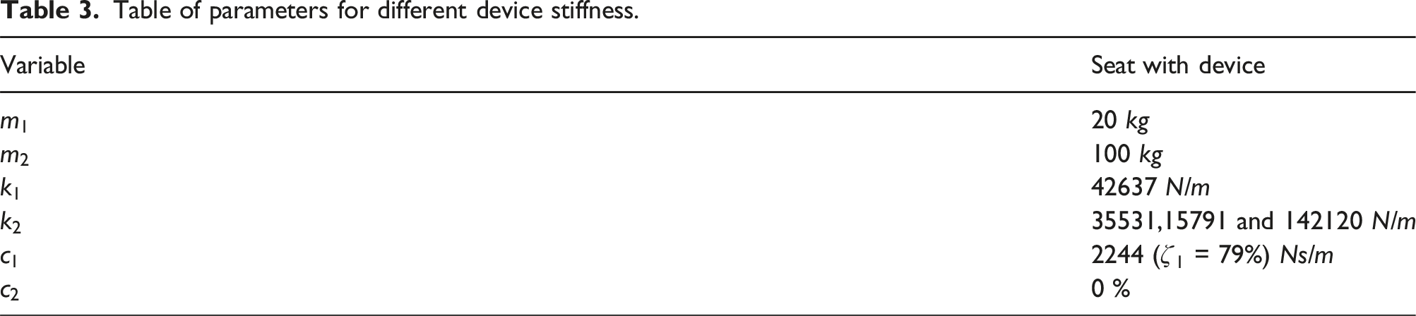
Since the natural frequency of the seat will be an inherent property of the OEM seat and operator mass, and it is not intended for the OEM seat properties to be modified, it is convenient for the simulation to fix the natural frequency of the OEM seat. For this situation, a SDOF natural frequency of 3 Hz was chosen as determined in the SDOF seat suspension test. Therefore, stiffness of the OEM seat can be determined for this situation. These ratios were selected to demonstrate a reduced device natural frequency and an increased device natural frequency within a realistic range compared to the OEM seat.
The assumption that input vibration does not cause the device to exceed the designed travel limits simplifies the model further to avoid the case where the device travel limits are exceeded leading to interaction with the end-stops. The masses have been selected for simplicity and correspond to a 100 kg operator and a mass ratio of
The plots for the different frequency ratios for are shown in Figure 8. Theoretical transmissibility of (a) Mass 1 and (b) Mass 2 for a 2-DOF system with different frequency ratios 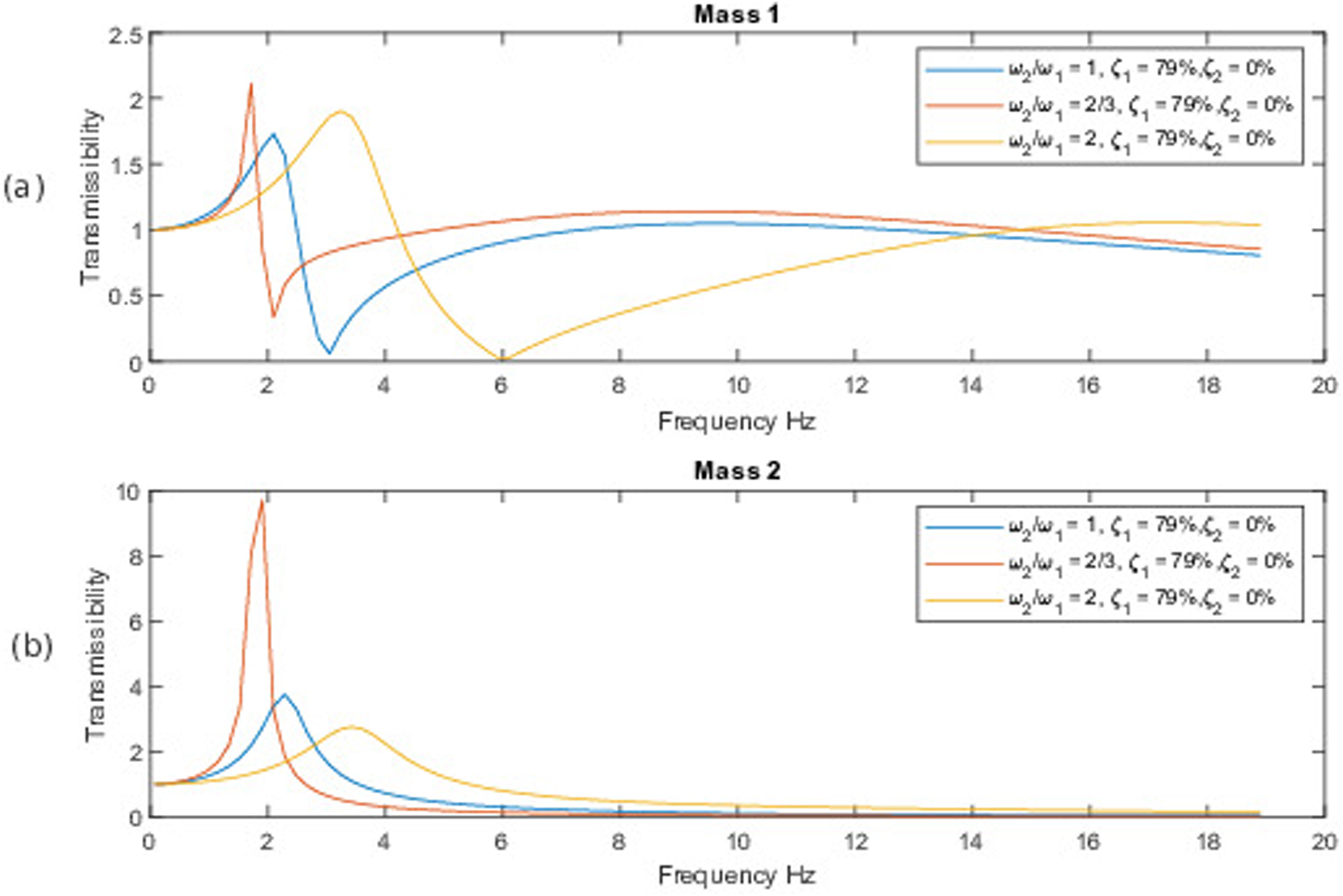
The peak transmissibility of Mass 1 for all frequency ratios occurs between 1.5 and 3.5 Hz with the maximum transmissibility of
Prototype simulation results
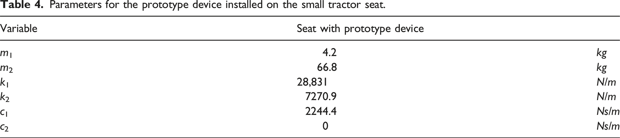
Parameters for the prototype device installed on the small tractor seat.
Each figure shows a plot for minimum damping (ζ = 5%), critical damping (ζ = 100%) and when using a bang-bang control strategy. The frequency range for these simulations was reduced from 0.5–18.9 Hz to 0.5–13 Hz as the plots become asymptotic above 10 Hz. Reducing the range to 13 Hz also provides better resolution to the plots for visualization. Figure 9(a) depicts a 1.3 transmissibility peak at 1.1 Hz for Mass 1 when a damping ratio of ζ = 5% is used. When control Law 2 or ζ = 100% is used peak transmissibility is approximately 1.1. The peak transmissibility of Mass 2 (operator mass) when using a damping coefficient of ζ = 5% is approximately 5.5, which is approximately 5 times larger than the peak transmissibility of the system when control Law 2 or a damping coefficient of ζ = 100% is used. Theoretical transmissibility minimum damping, critical damping, and control Law 2 strategy for (a) Mass 1 and (b) Mass 2.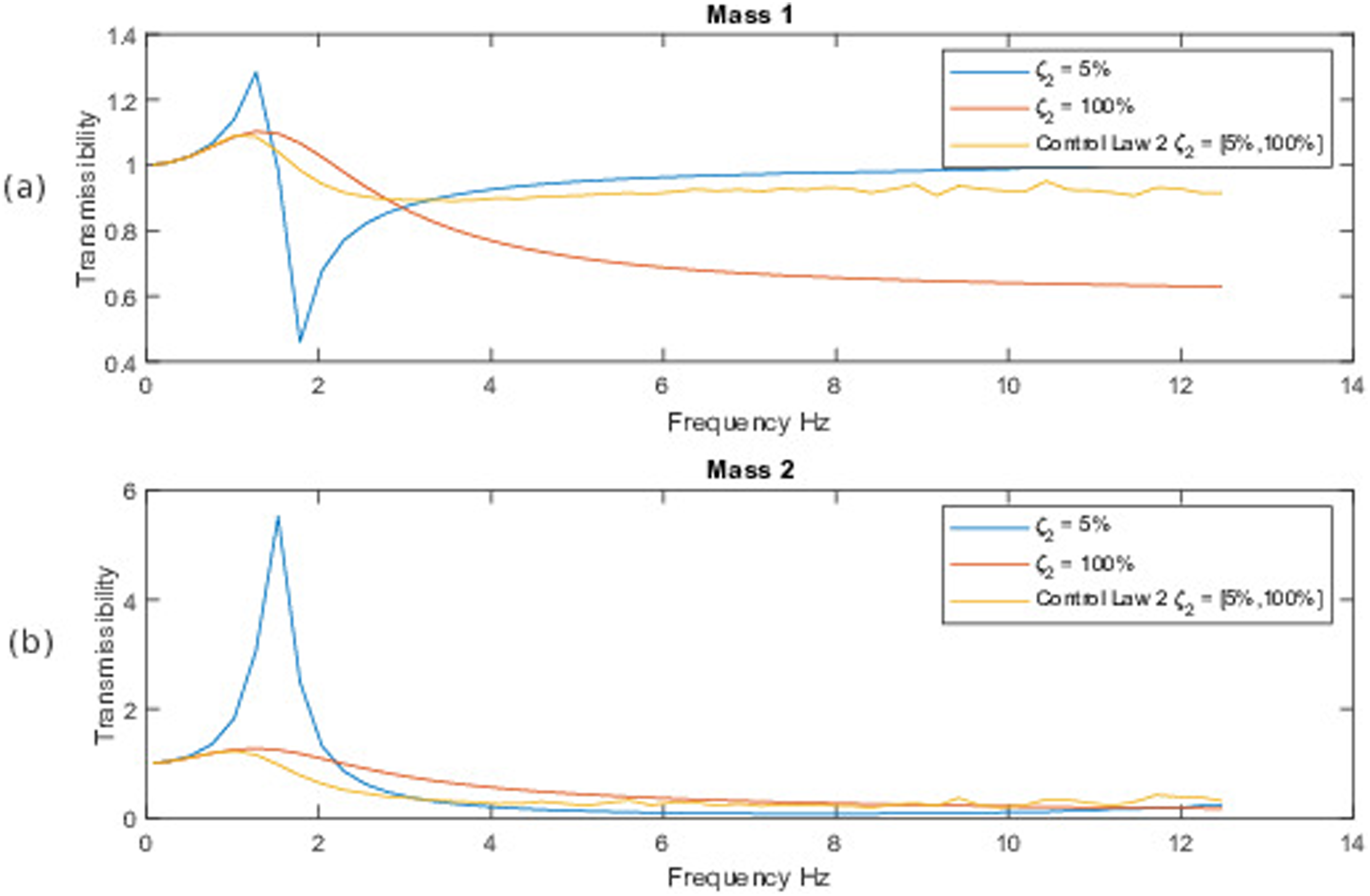
Figure 10 shows the transmissibility of system compared with the results using control Law 3. For a damping coefficient of ζ = 5%, the peak transmissibility of Mass 1 is approximately 1.3. On the other hand, when using a damping coefficient of ζ = 100% or control Law 3, the peak transmissibility is 1.1. Additionally, for frequencies higher than 5 Hz, the transmissibility of Mass 1 when using maximum damping is 0.6, while minimum damping and control Law 3 show similar transmissibility values of approximately 1. Figure 10(b) shows the transmissibility of the operator mass (Mass 2), with a peak transmissibility of 5.5 when utilizing minimum damping, and a peak transmissibility of approximately 1.2 when utilizing maximum damping or control Law 3. From 6 to 12 Hz, all vibration attenuation strategies have similar transmissibility results, however, maximum damping has a slightly higher transmissibility. Theoretical transmissibility of (a) Mass 1 and (b) Mass 2 using minimum damping, critical damping, and control Law 3 strategy.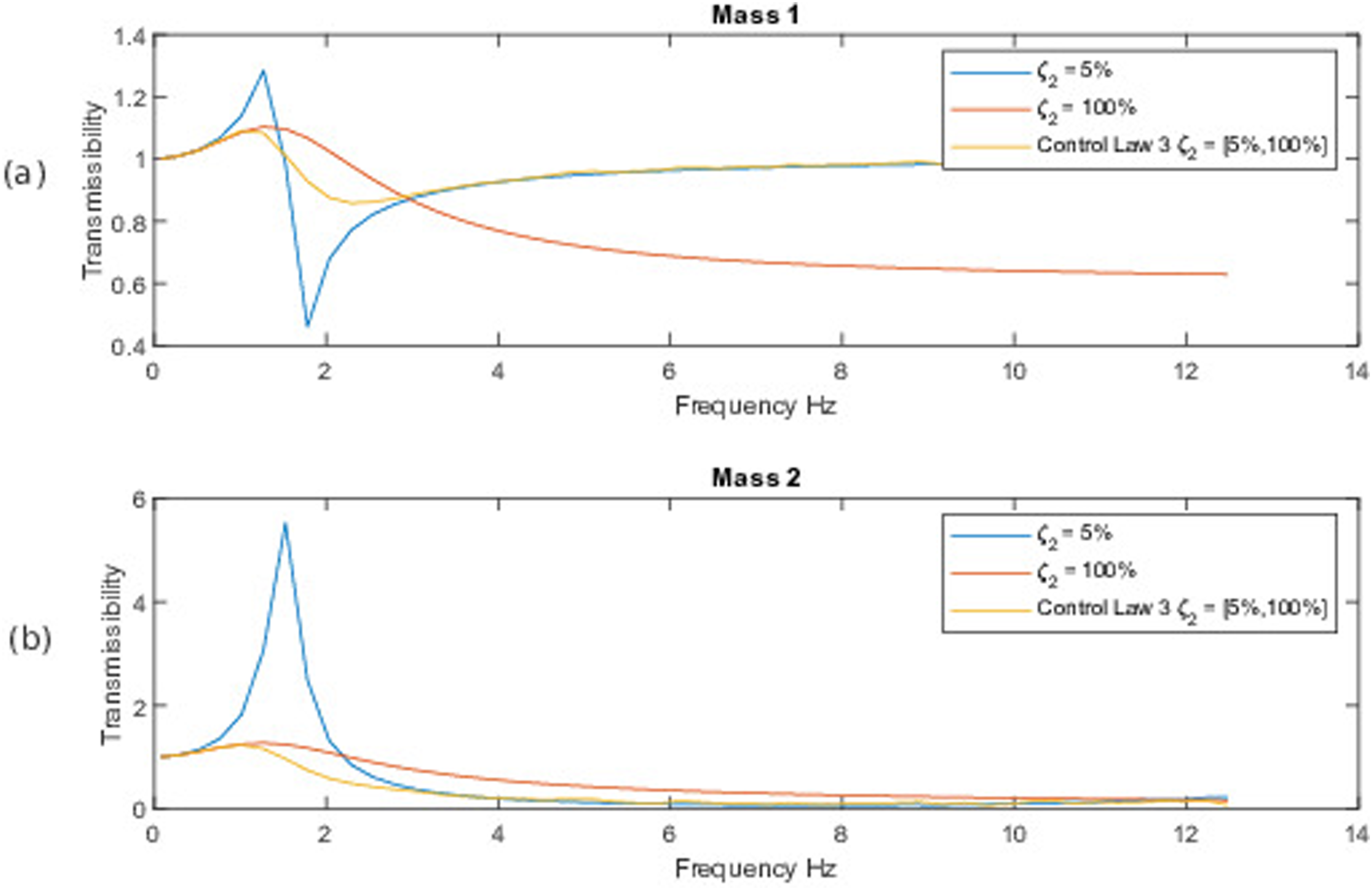
Sensitivity to mass and stiffness
The previous simulations consider only one set of variables of the OEM seat suspension and are not generalized for all seat suspensions. To better understand how uncertainties with OEM seat stiffness and how different operator masses (Mass (2) affect the response, simulations were conducted with reduced and increased OEM stiffness and mass. Simulation of a tractor seat with the prototype device installed was carried out and the results are shown in Figures 11 and 12. In this situation, the operator mass was lowered from 100 kg in the previous simulations to 66.6 kg as this was a limiting factor for the robot displacement at higher frequencies in its allowable range. The sprung weight of the OEM seat components was measured to be 4.2 kg. For the device as built, this means that the mass ratio for the two masses was increased from 5, as in Figure 10, to (a) mass ratio of 15.9. Transmissibility of (a) Mass 1 and (b) Mass 2 with changes in device stiffness. Transmissibility of (a) Mass 1 and (b) Mass 2 with changes in operator mass (Mass 2).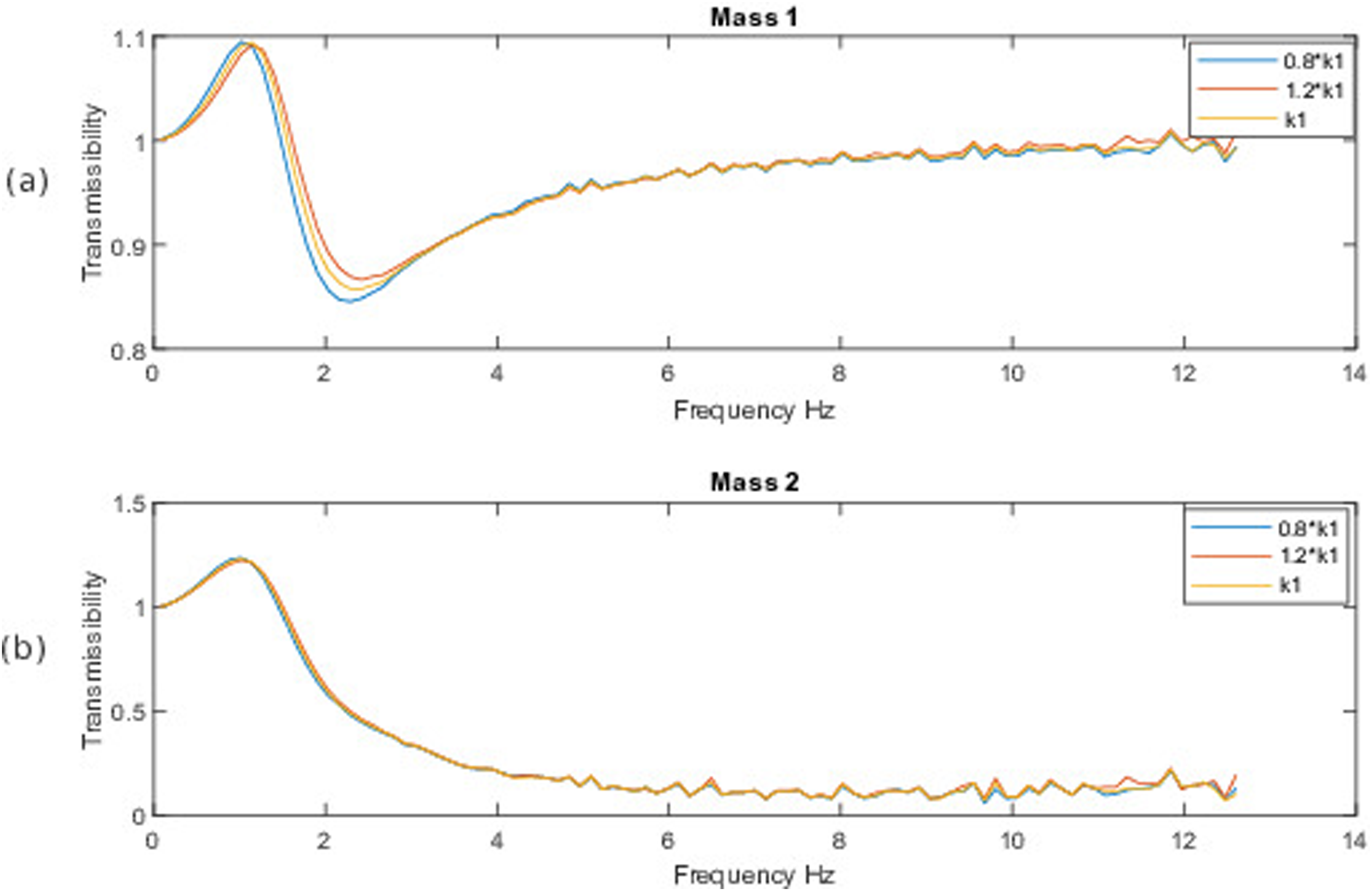
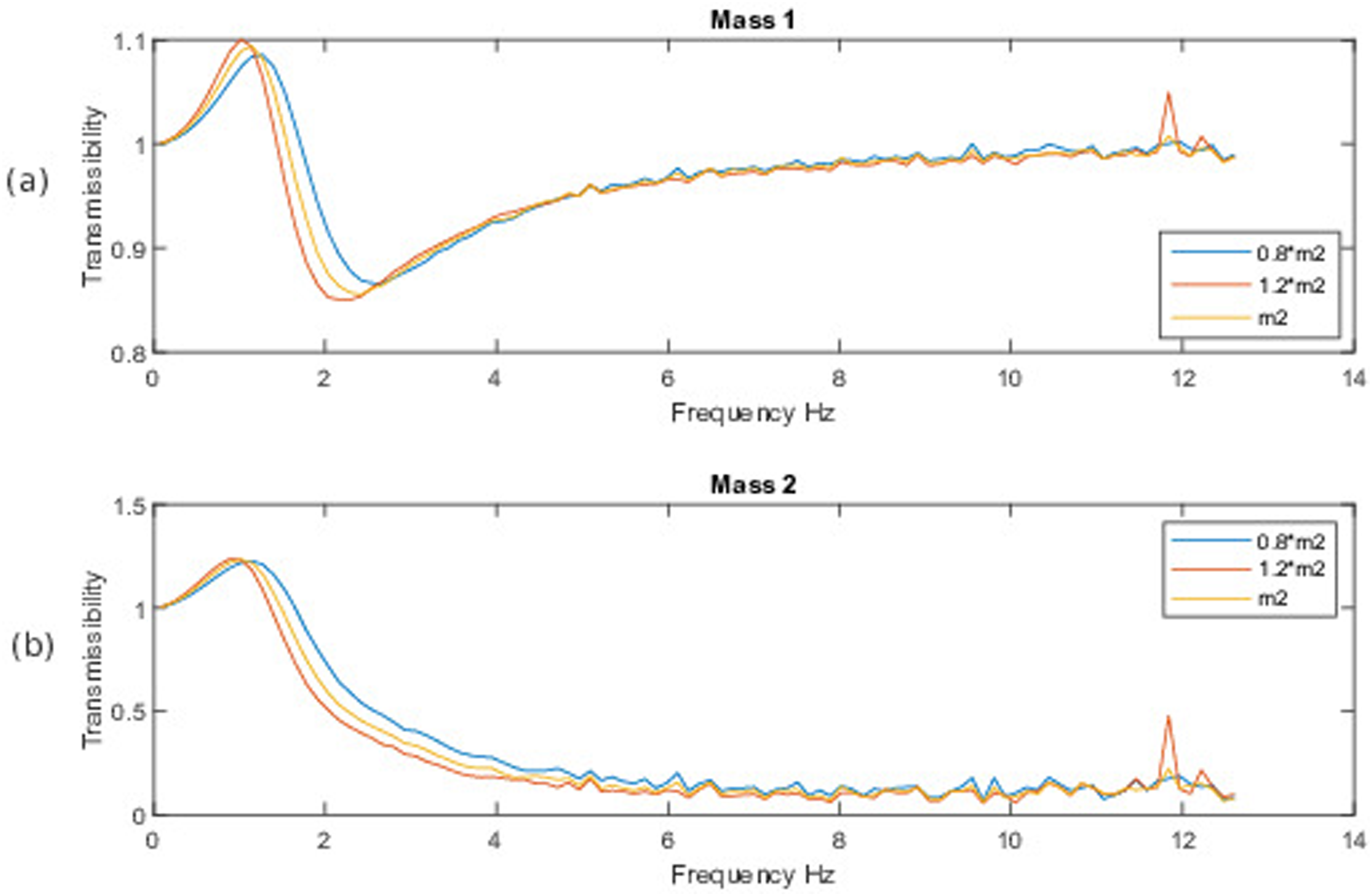
Both simulations were completed using control Law 3 as this control strategy provided the biggest transmissibility reduction. Figure 11 shows changes in transmissibility when adjusting stiffness of the device. Figure 12 shows how the transmissibility changes with changes of Mass 2. Figure 11 shows a change of transmissibility of approximately ±0.05 for Mass 1 with ±20% changes in stiffness (k1), and minimal changes in transmissibility of Mass 2 with the same variations in stiffness (k1).
Mass 1 shows variations in transmissibility of approximately ±0.025 between 1 and 2.5 Hz, and minimal variations throughout the rest of the frequency range (0–12 Hz). Transmissibility for Mass 2 (operator mass) varies approximately ±0.1 from 1 to 5 Hz with smaller variations from 5 to 12 Hz.
Model validation
Experiments were conducted to test the proposed cushion design. Figure 13 shows the experimental transmissibility of Mass 2 for the OEM seat and the OEM seat with the prototype installed in place of the OEM seat cushion. Transmissibility is expressed as a function of the frequency ratio where the frequency ratio is the ratio of the vibration frequency to the natural frequency of the system. The predicted transmissibility from the simulations are in good agreement with the experimental counterpart. The peak transmissibility for the prototype device was 1.2 for the simulation and 1.1 for the experiment. Transmissibility of Mass 2 with a 66.6 kg operator seated mass for the OEM seat and the prototype using Control Law 3.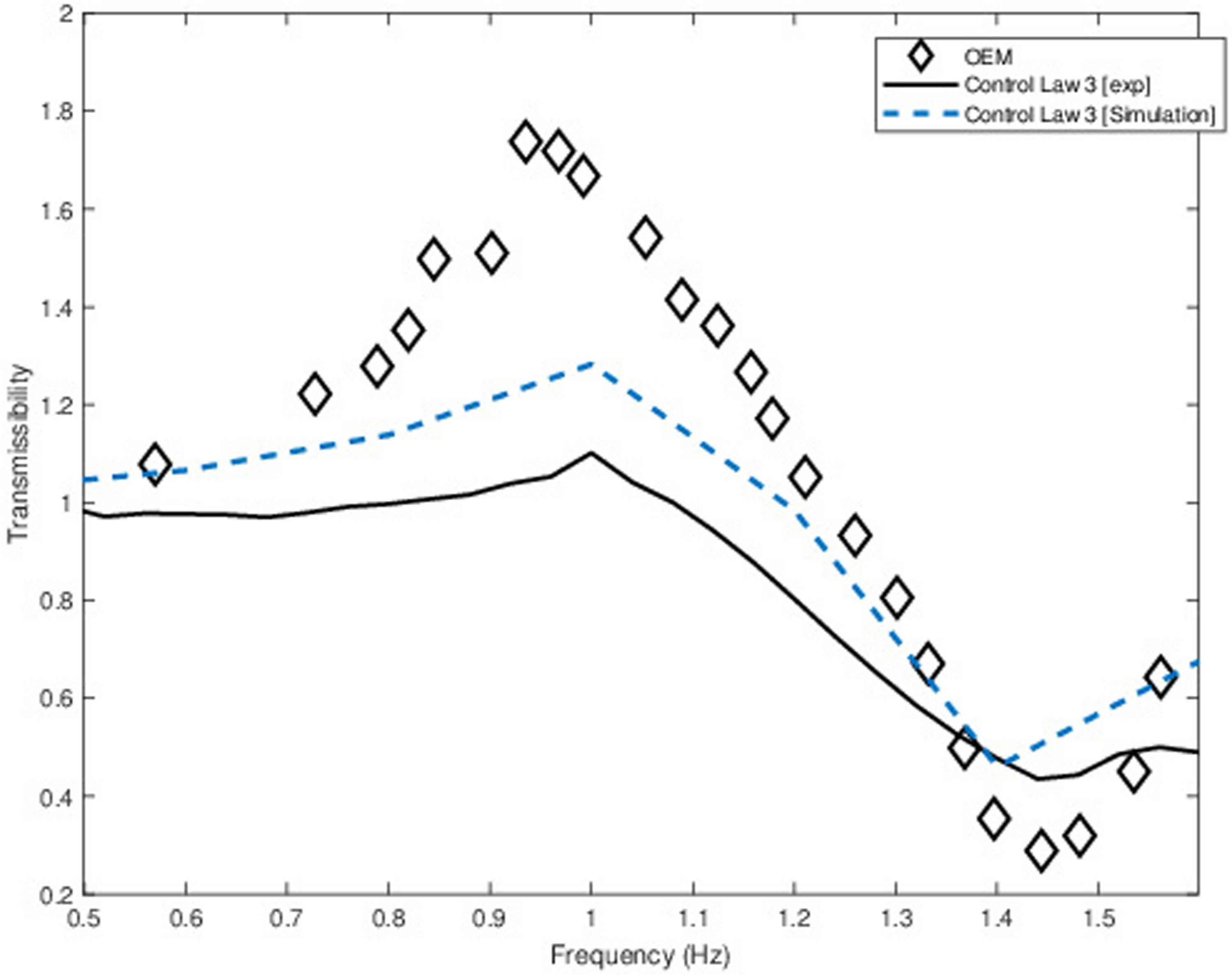
The prototype device results in lower transmissibility to Mass 2 (the operator mass) during vertical vibration exposure compared to the OEM seat (Figure 13). When Control Law 3 is used, the peak transmissibility to Mass 2 for the OEM seat is approximately 80% higher than the transmissibility to Mass 2 for the prototype device. The experiment results indicate superior vibration attenuating performance of the prototype device for all frequency ratios except for 1.3 to 1.6. However, in this frequency ratio range, the difference in transmissibility between the complete OEM seat and the OEM seat with the prototype cushion installed is small with the largest difference being approximately 0.1. However, at this frequency ratio, the transmissibility is quite low (<0.6).
When analysing the acceleration transmissibility, the experimental data indicates 11.5% lower acceleration transmissibility to Mass 2 at the resonant frequency when using Control Law 3 compared to the OEM seat (Figure 14). The peak acceleration transmissibility to Mass 2 occurs at approximately 1.3 Hz for the simulated Control Law 3 data, and approximately 2.6 Hz for the experimental Control Law 3 data. From 1 to 9 Hz, apart from 5.6 to 5.9 Hz, Control Law 3 reduces the transmissibility to Mass 2, when compared to the OEM seat. In addition, the experimental data appears to show a secondary resonance at just below 6 Hz for both the OEM seat and Control Law 3 data. ISO 2631-1 weighted acceleration transmissibility of Mass 2 with a 66.6 kg operator seated mass for the OEM seat and the prototype using Control Law 3, and the simulated Control Law 3 data.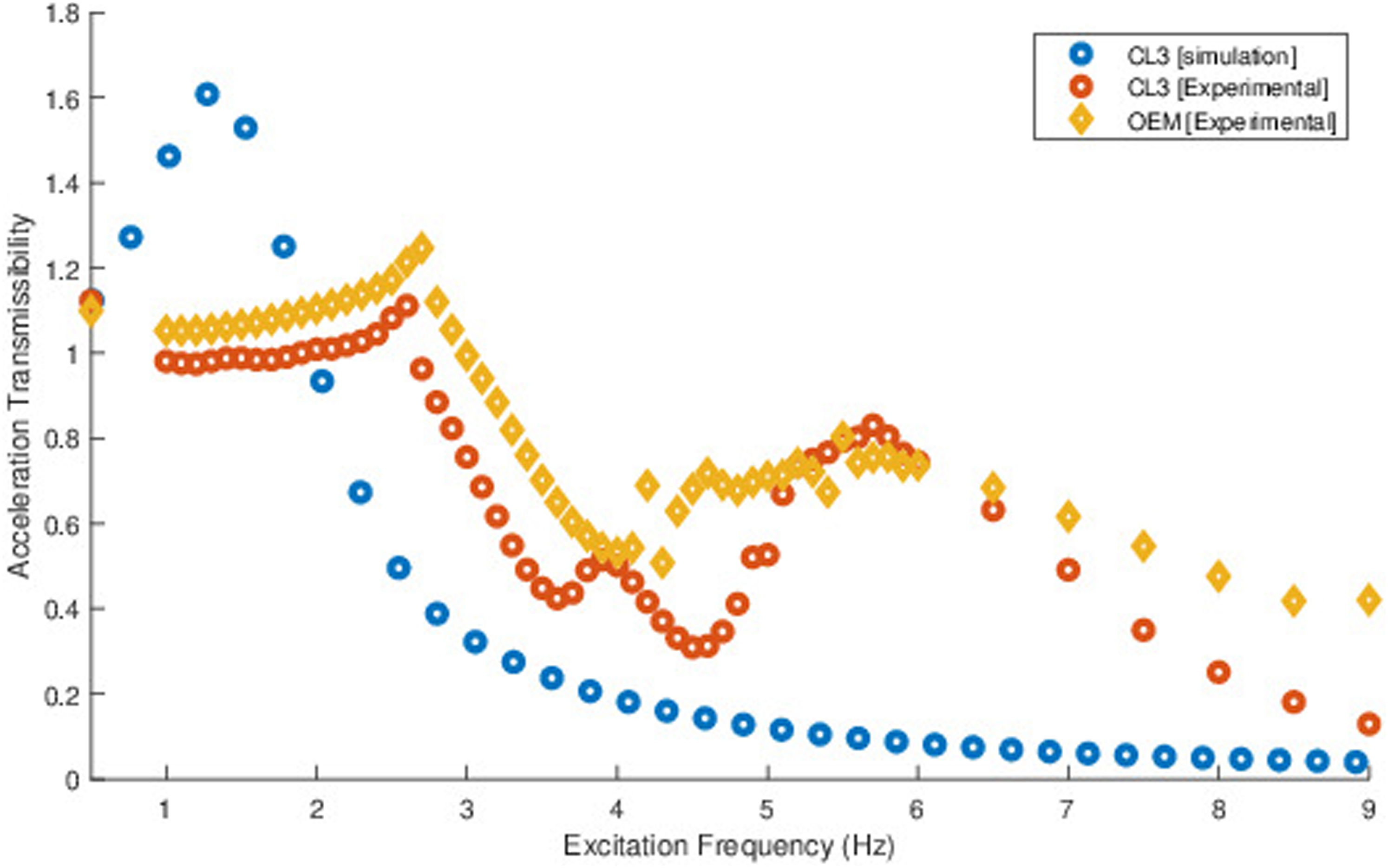
Discussion
For the typical TMD shown in Figure 7, when Mass 1 is much greater than Mass 2, there is complete isolation of Mass 1 at the designed natural frequency of the absorber. This type of system is not practical for a seat suspension as the desired outcome is the isolation of Mass 2 (operator mass).
The response shown in Figure 8 corresponds to a system where Mass 2 is much heavier than Mass 1. Increasing device stiffness reduces the maximum transmissibility for Mass 2 but is not as effective above the cut-off frequency. When the device stiffness is designed for a natural frequency that is lower than the OEM seat stiffness, the device effectively isolates Mass 2 above the cut-off frequency. However, the drawback of a low device stiffness is the requirement for more damping to limit the maximum transmissibility below the cut-off frequency.16,19 Ideally, device damping would have a large dynamic range for control to allow for very low damping when turned off and very high damping when on. In practice, commercially available controlled dampers have a limited dynamic range. The importance of limiting peak transmissibility means that damper selection will err on the side of higher damping.
Control Law 3 provides a reduction in peak transmissibility of approximately 5.5 times (Figure 10) when compared to minimal damping, as well as approximately equal peak transmissibility to the maximum damping system. It should be noted that from 1.5 to 12 Hz the maximum damping system has approximately double the transmissibility to Mass 2 when compared to control Law 3. Therefore, control Law 3 is more effective than minimal or maximum damping passive seat suspension systems when aiming to reduce vibration transmissibility to the operator.
The control Law 2 and 3 simulations have improved ability to reduce transmissibility of vibration to the operator when compared to the semi-active MR damper system proposed by Bai et al. 37 Control Law 2 and 3 are more effective at reducing peak transmissibility to the operator than the passive suspension systems without a negative stiffness structure (NSS). 26 Additionally, both control laws show equal performance to the active seat suspension with NSS that was evaluated by Danh et al. 26 The simulation and experiment utilizing Control Law 3 have reduced peak transmissibility compared to all NSS suspension systems presented by Danh et al. 26 as well as equivalent or reduced peak transmissibility compared to the semi-active seat suspension designs with different controllable torque presented by Bai et al. 37
However, control Law 3 shows lower transmissibility over the entire frequency range above resonance. With control Law 3, more energy is transferred to Mass 1 from Mass 2. However, when the existing seat incorporates armrest mounted controls, this may have a negative effect during operation as the seat mounted controls have been shown to increase head and neck motion of the operator when exposed to WBV compared to steering wheel mounted controls. 38 Additionally, the relative movement of the operator with controls in the cab may be a distraction. 2
Although the acceleration transmissibility curves for the simulated and experimental Control Law 3 data are not very similar, the experimental Control Law 3 data shows decreased acceleration transmissibility compared to the OEM seat. In addition, the experimental performance of Control Law 3 is superior to simulated Control Law 3 from 0 to 2 Hz. The input displacement to the simulation was a sinusoid at a particular frequency. Although the same input sinusoid was given to the robot, the experimental data contained low amplitude noise at various frequencies, which could explain some differences in the data. In the future, motion capture should be used to capture displacement at the Input, Mass 1 and Mass 2. These data can be used to ensure the input excitations are identical. In cases where they are not identical, the experimental displacement data could then be used as an input to the simulation. This would also be beneficial when testing with field vibration profiles. The assumption of a damping range of 5–100% may not be conservative enough due to practical limitations, however, the concept for a low stiffness seat cushion with semi-active damping is shown to be effective. Development of a field ready version of the prototype may be challenged by the accessibility of commercially available and industrially proven controlled damping devices. Device operation was simulated for controlled damping in this work, but the device may also be effective under controlled stiffness.
The assumption that the base motion does not cause the device to exceed its design travel limits will be limiting when testing a device in a field situation. In practice, base motion of off-road mobile equipment will be much larger than 5 mm peak to peak. However, the model will serve a useful purpose for designing the stiffness and damping values for a field ready prototype and will help define the form factor for the device as suitable components will need to be selected or designed. The travel limits for the future prototype will be determined by the space requirements of the physical components and end-stop design will be determined by the availability of space within the device. Interaction of the end-stop mechanics can be incorporated into the model at that development stage.
Changes in seat stiffness and damping can impact seat performance. For example, a stiff material limits the movement of the cushion and may improve dynamic characteristics throughout the entire frequency range. However, sitting on a hard material for extended lengths of time may increase pressure on parts of the gluteal musculature thus affecting posture and comfort. 16 Alternatively, a soft cushion with low damping will cause undesired amplification of vibration at low frequencies and adds a second degree of freedom (DOF) to the seat suspension. Thus, for practical applications, the design should be robust enough to handle uncertainties with OEM seat stiffness variability as well as a range of operator masses.14,24 Simulation results (Figure 11) indicate only slight variations in frequency response of both Mass 1 and Mass 2 (operator mass) for a 20% variation in OEM seat stiffness. Similarly, a 20% variation in operator mass did not result in a drastic change in model response for both Mass 1 and Mass 2 (Figure 12). Thus, the device is robust when exposed to variations of 20% OEM seat stiffness or operator mass (Mass 2).
Conclusions
A model for a semi-active device that could replace a seat cushion on an OEM suspension seat was developed to predict device vibration transmissibility. Values for seat stiffness and damping were simplified at first to determine the generalized shape of the transmissibility curve for this type of device. A more realistic set of values for a typical operator seat were determined and used to assess the performance of the prototype device with a Bang-Bang control strategy. Results of the simulation showed reduced vibration transmissibility to the operator over the whole frequency range when compared to a device with a fixed damping coefficient.
Sensitivity to changes in operator mass as well as variability in seat suspension stiffness were also investigated and shown to have only a small effect on device performance.
The model demonstrates the potential for this type of device to reduce WBV transmissibility and was used to develop a prototype device for laboratory testing. The frequency response curves will be useful during the development of future prototypes that can be deployed for field testing. This work has showed promising performance, reducing vibration at the seat-operator interface. The validation of the prototype’s performance is limited by the use of a lumped mass and sinusoidal base excitation. Future work includes testing with human participants and field vibration profiles to further validate device performance. Further investigation, including vibration transmission to the head, using a dynamic model of the human body with increased degrees of freedom should be considered. Currently, the model is limited to small amplitudes using the assumption that base motion does not cause the device to exceed its travel limits. The model could be improved to include the effects of the end-stops for travel of the device to investigate the effect of large magnitude vibration. Future testing will include investigation of both simulated and experimental performance when exposed to realistic vibration with device displacement constraints.
Footnotes
Author contributions
All authors contributed to the writing and editing of this article. In addition, Alexander Barrie conducted the simulations, and built and tested the prototype. Janik Habegger conducted the model validation experiments.
Declaration of conflicting interests
The authors have no potential conflicts of interest with respect to the research, authorship, and/or publication of this article. However, they do declare that three of the five authors hold a provisional patent on the device presented in this paper as follows: Barrie, A., Oliver, M. and Hassan, M. Whole Body Vibration Transmission Reduction Device; US Patent Application No. 17/612,011, November 17, 2021.
Funding
The author(s) disclosed receipt of the following financial support for the research, authorship, and/or publication of this article: This work was supported by the Natural Sciences and Engineering Research Council of Canada (Discovery Grants to the fourth and fifth authors, and a Research Tools and Instruments Grant to the fifth author) and the Ontario Ministry of Agriculture, Food and Rural Affairs Gryphons Leading to the Accelerated Adoption of Innovative Research Grant to the first, fourth and fifth authors.
Appendix
Displacement amplitude, excitation frequency, and root mean square acceleration details for the sine sweep used to determine the natural frequency of the seat.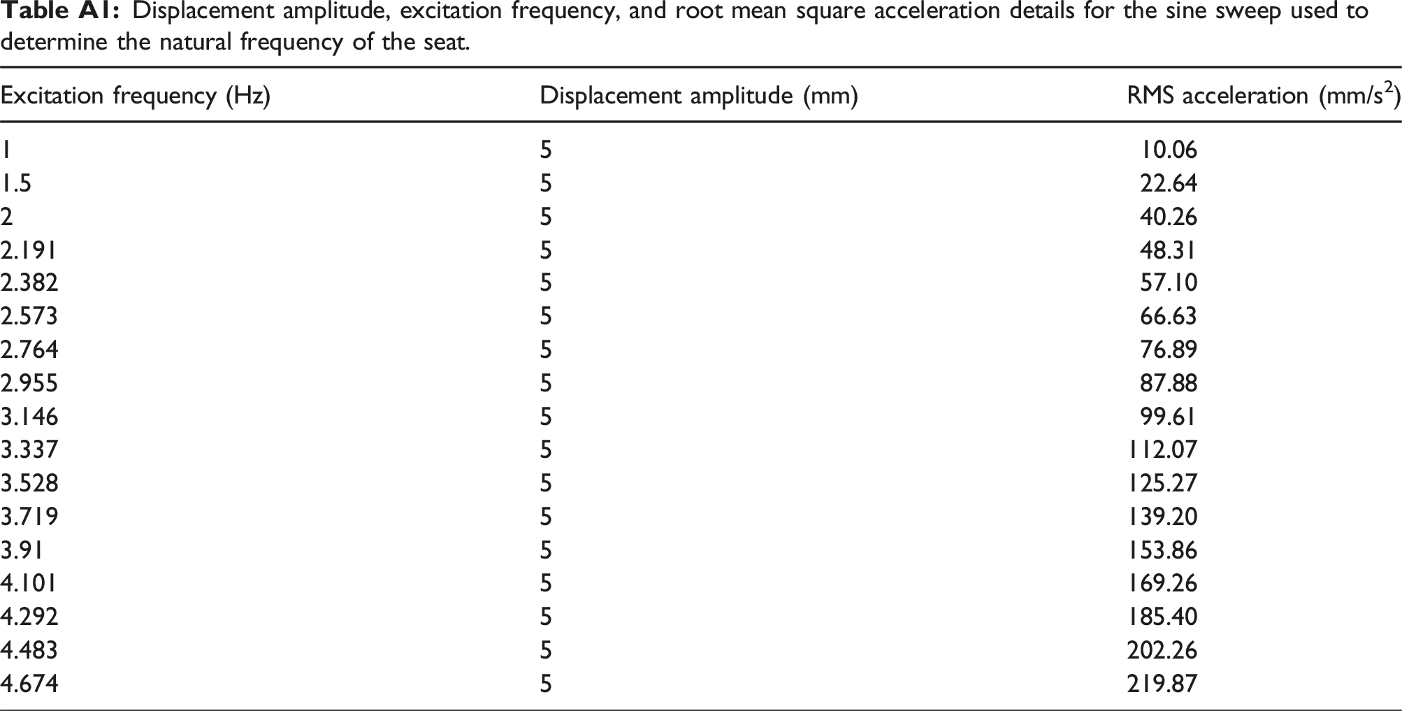
Excitation frequency (Hz)
Displacement amplitude (mm)
RMS acceleration (mm/s2)
1
5
10.06
1.5
5
22.64
2
5
40.26
2.191
5
48.31
2.382
5
57.10
2.573
5
66.63
2.764
5
76.89
2.955
5
87.88
3.146
5
99.61
3.337
5
112.07
3.528
5
125.27
3.719
5
139.20
3.91
5
153.86
4.101
5
169.26
4.292
5
185.40
4.483
5
202.26
4.674
5
219.87
Displacement amplitude, excitation frequency, and root mean square acceleration details for the base excitation used to validate the device and its control laws.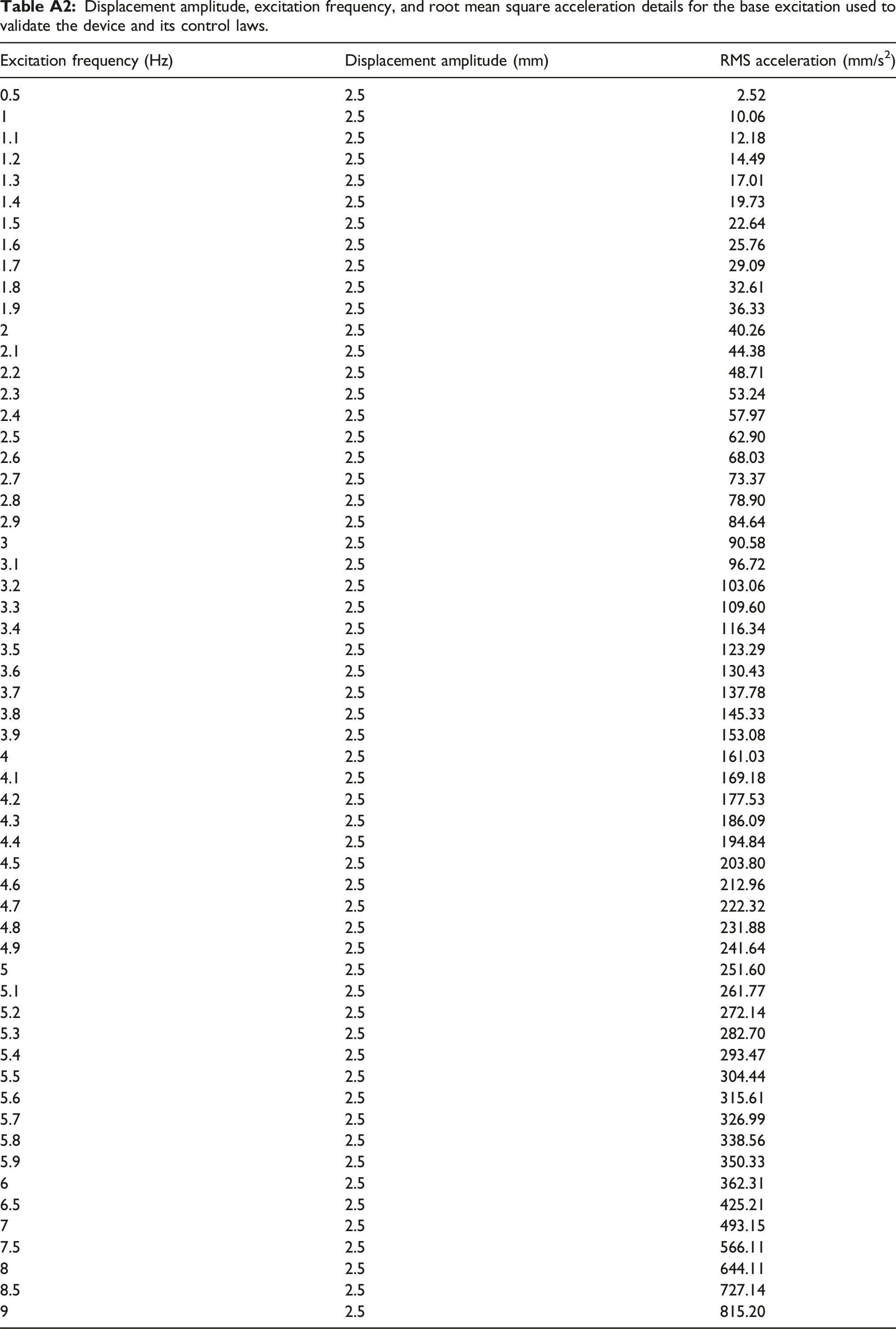
Excitation frequency (Hz)
Displacement amplitude (mm)
RMS acceleration (mm/s2)
0.5
2.5
2.52
1
2.5
10.06
1.1
2.5
12.18
1.2
2.5
14.49
1.3
2.5
17.01
1.4
2.5
19.73
1.5
2.5
22.64
1.6
2.5
25.76
1.7
2.5
29.09
1.8
2.5
32.61
1.9
2.5
36.33
2
2.5
40.26
2.1
2.5
44.38
2.2
2.5
48.71
2.3
2.5
53.24
2.4
2.5
57.97
2.5
2.5
62.90
2.6
2.5
68.03
2.7
2.5
73.37
2.8
2.5
78.90
2.9
2.5
84.64
3
2.5
90.58
3.1
2.5
96.72
3.2
2.5
103.06
3.3
2.5
109.60
3.4
2.5
116.34
3.5
2.5
123.29
3.6
2.5
130.43
3.7
2.5
137.78
3.8
2.5
145.33
3.9
2.5
153.08
4
2.5
161.03
4.1
2.5
169.18
4.2
2.5
177.53
4.3
2.5
186.09
4.4
2.5
194.84
4.5
2.5
203.80
4.6
2.5
212.96
4.7
2.5
222.32
4.8
2.5
231.88
4.9
2.5
241.64
5
2.5
251.60
5.1
2.5
261.77
5.2
2.5
272.14
5.3
2.5
282.70
5.4
2.5
293.47
5.5
2.5
304.44
5.6
2.5
315.61
5.7
2.5
326.99
5.8
2.5
338.56
5.9
2.5
350.33
6
2.5
362.31
6.5
2.5
425.21
7
2.5
493.15
7.5
2.5
566.11
8
2.5
644.11
8.5
2.5
727.14
9
2.5
815.20