
Abstract
A type of pneumatic artificial muscle damping seat used in crawler construction vehicle is introduced. When pneumatic artificial muscle works, nonlinear problem happens. This often makes its working performance become worse. Therefore, a self-tuning fuzzy PID controller is used for pneumatic artificial muscle damping seat to decrease this influence. A simplified three degrees of freedom mathematical model of seat-vehicle body-crawler chassis is established. The vibration damping characteristics of the pneumatic artificial muscle seat are obtained using Matlab/Simulink toolbox. Under four different working conditions of crawler construction vehicle, vertical accelerations and displacements are compared between the new pneumatic artificial muscle damping seat and traditional seat. The simulation results show that the pneumatic artificial muscle seat could get better damping properties. To verify the analytical model, experiments were performed on C and G roads. The simulation results show reasonably good agreements with the experimental data. These research results could provide references for further development of pneumatic artificial muscle-type damping seat.
Introduction
Many crawler construction vehicles often travel and work over rough roads. Violent vibration and shock happen and vibration frequency is usually located between 3 and 8 Hz. 1 Thus, when drivers work under this bad condition for a long time, they will feel discomfort and tiredness. Accordingly, their working efficiency decreases.2,3 There are many ways to improve this situation. Among these methods, some effective suggestions about seat suspension system have been given. For instance, a kind of passive suspension seat was installed in some vehicles to reduce the low-frequency vibration. 4 Bouazara et al. 5 analyzed the vibration isolating properties of two different suspension seats, one of which consisted of a mechanical spring and an inclined hydraulic damper, while the other comprised a pneumatic spring with a semi-actively controlled hydraulic damper. Hostens et al. 6 presented an improved design of air suspension seats which were installed in mobile agricultural vehicles. This kind of seat used an air-spring, an additional air reservoir volume to lower the structural natural frequency and air damping by using a throttle valve. These related studies about seat’s suspension provide assistance to the new design in this work. However, studies on pneumatic artificial muscle (PAM) damping seat are limited, particularly when for use in crawler construction vehicles.
PAM’s characteristic is similar to animal skeletal muscle. Its force to weight ratio is bigger and when it works, and it consumes little compressed air.7,8 Thus, its application has caused great concern for many researchers. The PAM was first used for artificial limb research in the 1950s. Since then, it has widely been applied in the robotics industry.9,10 In a later study by Zhang et al., 11 PAM was also used in parachute systems as soft-landing retraction and steering control device. In addition, Ostasevicius et al. 12 studied an active car suspension with the FESTO PAM. By looking through above papers, it may be found that although PAM has been applied in many applications, it is the first time to be used in reducing vibration of crawler construction vehicles. The structure of PAM damping seat is simple; it could be made easily. More importantly, the ride comfort of crawler construction vehicle could be improved to some extent by installing PAM damping seat. Therefore, it is an attractive alternative for manufacturing enterprise of construction vehicles. In addition, it should be noted that nonlinear characteristics exist during PAM working so that PAM seat need to be controlled. Presently, many control methods have been adopted, which include PID, neural network, fuzzy control (FC) and so on.13–17 As is well known, PID control has good performance, easy structure and other merits. FC is used to control nonlinear systems. Moreover, the use of a self-tuning FC can avoid the trouble of redesigning control rule sets. Therefore, a self-tuning fuzzy PID controller is applied to the PAM damping seat in this paper, which combines the PID control’s advantages with the merits of FC.
A type of PAM damping seat used in crawler construction vehicle is introduced in the paper. Because the working conditions of crawler construction vehicle often vary, whether or not PAM could be used for the seat of crawler construction vehicle is not known. Therefore, considering the particularity of the new PAM damping seat’s structure and application, it is necessary to obtain its vibration reduction characteristic. For this purpose, Matlab/Simulink software is adopted as the simulation tool. The paper is structured as follows: Introduction section presents the development of mathematical model of PAM; Mathematical model of PAM section sets up the model of the PAM and governing equations of seat-vehicle body-crawler chassis; Applications of the PAM in seat section presents the simulations of vertical movement of PAM damping seat and traditional seat and experiments to verify the analytical model of PAM damping seat. The research results could provide references for further application of PAM seat in various vehicles.
Mathematical model of PAM
The schematic of PAM structure is shown in Figure 1. It is mainly composed of a rubber inner tube and a braided mesh shell.
Schematic of PAM structure.
Mass and energy transfer equation of the air
Here, the isothermal and adiabatic states are assumed during charging and discharging of the compressed air. So, when compressed air is supplied to the inner tube, the PAM may expand like a balloon. But its expansion is restricted by the outer shell. At this time, the government equation of mass and energy transfer of the air can be expressed as

Mechanical behaviours of the PAM
Many models could be used to describe the mechanical behaviours of the PAM.19,20 In this research, the PAM is considered as a mechanical spring. Equivalent diagram of these two systems is shown in Figure 2. It may be seen that the PAM’s characteristic resembles the mechanical spring system when a pulling force is exerted on them. Here, the stiffness of the latter is fixed, and it is related with the material characteristic and the structure of spring. However, for the PAM, its stiffness not only has relevance to the abovementioned characteristic but also varies with the gauge compressed air pressure (Pg) of the inner tube of PAM. The stiffness of the PAM (k) is given by
Equivalent diagram of PAM and mechanical spring.

When the PAM contracts at a given air pressure without pulling forces, its un-stretched length is considered as l
u
. When the contracted PAM is operated with a pulling force (Fp), it will move as the spring mechanism and its instantaneous length is denoted as l. So, from Figure 2, the relationship of the length ls, lu and l can be written as

Based on the above analysis, the ideal contracting force adversely generated by one PAM is obtained by
21

However, it should be noted that the inner tube of the PAM is made of rubber material, so elastic deformation could happen in it. That is, when its length changes, an elastic force will exist. Here, the elastic force can be written as


Applications of the PAM in seat
Description of the PAM damping seat
Working principle of the PAM damping seat
Crawler construction vehicles usually work under heavy loads at a low speed, the predominant vibration is in the vertical plane and the operator is very sensitive to the vertical accelerations.
22
That is, the comfort of seat mainly depends on its vertical movement. Therefore, much attention has been paid to the reduction of vibration and shock in the vertical direction. Working principle of the PAM damping seat is shown in Figure 3. It mostly consists of two groups of nearly identical PAM pairs. Initially, the PAM pairs keep their certain lengths at the given air pressure. When the seat is impelled by random loads, the PAM pairs could contract or stretch until they reach their new equilibrium lengths; consequently, the motion of the PAM damping seat could be controlled. As is shown in Figure 3(a), when the total direction of random loads exerted on seat is vertically upward, the PAM pairs placed in parallel under the seat are pressurized and contract nearly equally at a given pressure. On the contrary, the PAM pairs which are installed above the seat stretch by reducing their inner pressure. Similarly, when the seat is subjected to a downward load, the above group of PAM pairs contract and the under PAM pairs would stretch simultaneously (see Figure 3(b)).
Working principle of the PAM damping seat (a) the direction of loads is upward; (b) the direction of loads is downward.
Control system of the PAM damping seat
In order to overcome the nonlinear problem and achieve design goals, the movements of two groups of PAM pairs should be controlled reasonably. A schematic diagram of PAM damping seat control system is shown in Figure 4 where two sets of pressure transducers connected at the air inlet of the PAMs are used to observe the air pressure. The real move acceleration of the seat is detected by an acceleration transducer. In addition, the hardware includes a controller, which calculates the control input and controls high-speed on–off valve through D/A board. The air compressor is connected to the on–off valve. The PAM pairs are pneumatically driven by the proportional valves, which could set the air pressures of the two groups of artificial muscles at (p + Δ p) and (p–Δ p), respectively. As a result, the PAM damping seat could nearly keep its original position and the vehicle’s ride comfort is improved.
Schematic diagram of PAM seat control system.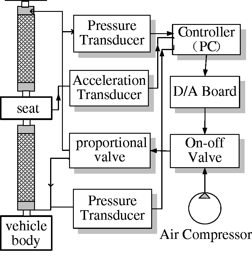
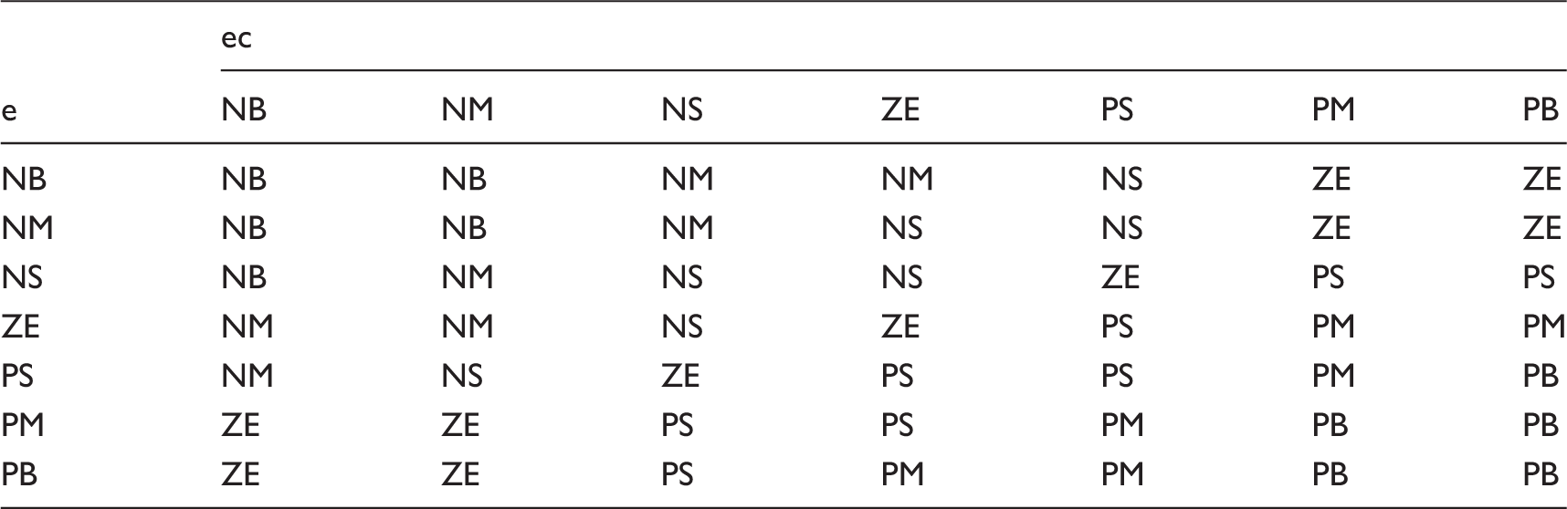
As mentioned above, a self-tuning fuzzy PID controller is adopted in this paper, and this is shown in Figure 5. Its main advantage is that it keeps the simple structure of the PID controller. Here, P stands for proportional part, I is integral part and D denotes derivative part in the controller. The PID parameters kp–ki–kd are tuned on-line by a fuzzy logic controller according to FC rules. The fuzzy logic controller uses the error e(t) and the rate of change in error (ec) as its inputs and it instantly examines e and ec. Here, e(t) is the error between the measured real seat vertical acceleration a and the expected acceleration value a0. Output of the controller can be expressed as
The block diagram of self-tuning fuzzy PID controller.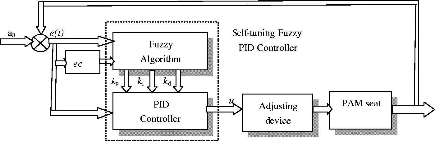

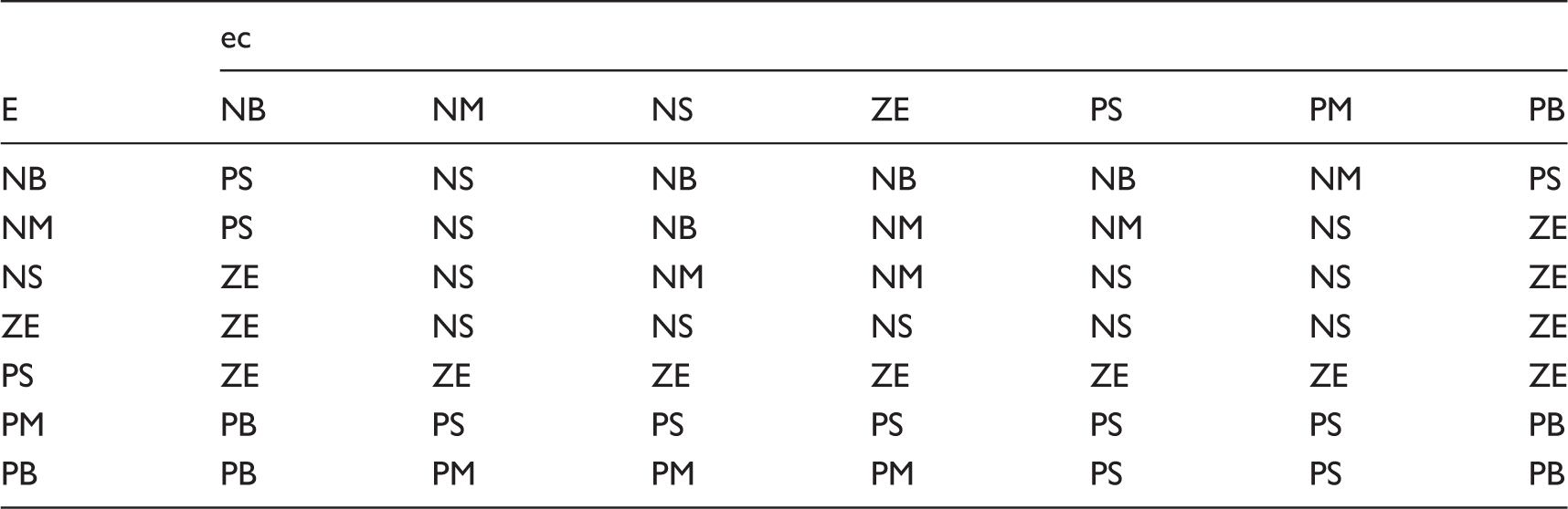
Fuzzy control rule-base for kp.
Fuzzy control rule-base for kd.
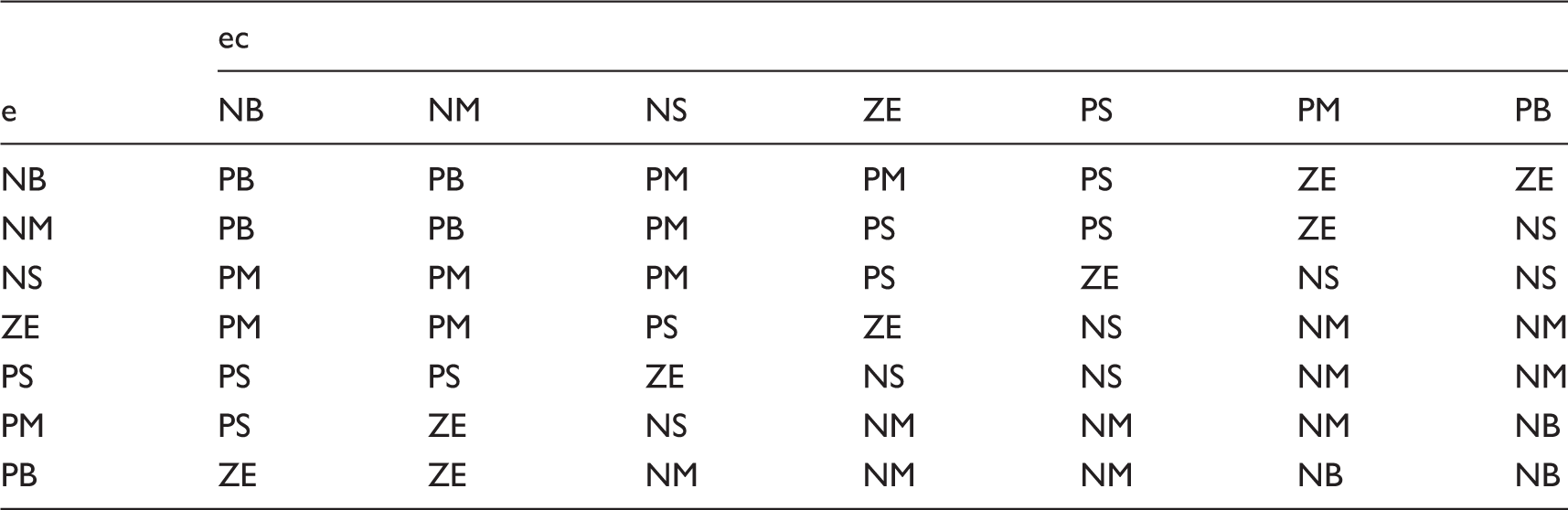
Fuzzy control rule-base for ki.
Mathematical model of seat-vehicle body-crawler mechanism
Governing equations of seat-vehicle body-crawler chassis
In order to predict the response of the PAM damping seat due to road roughness, a simplified three degrees of freedom (3-DOF) model of seat-vehicle body-crawler chassis is established in Figure 6 where the force F stands for the resultant force produced by two groups of PAM pairs, k3 and c3 are the stiffness and damping of conventional original seat in which PAM pairs are not installed. m3 is the total mass of the PAM damping seat system and the driver; the vehicle body is assumed to be rigid with mass m2. The vehicle suspension is modeled as the combination of a linear spring k2 and damper element c2. x1, x2 and x3 represent vertical displacements of the seat, vehicle body and crawler mechanism, respectively. The road roughness, represented by x0, is considered as a typical input of the whole model.
23
Crawler chassis is modeled with stiffness k1 and the mass m1.
3-DOFs model of seat-vehicle body-crawler chassis.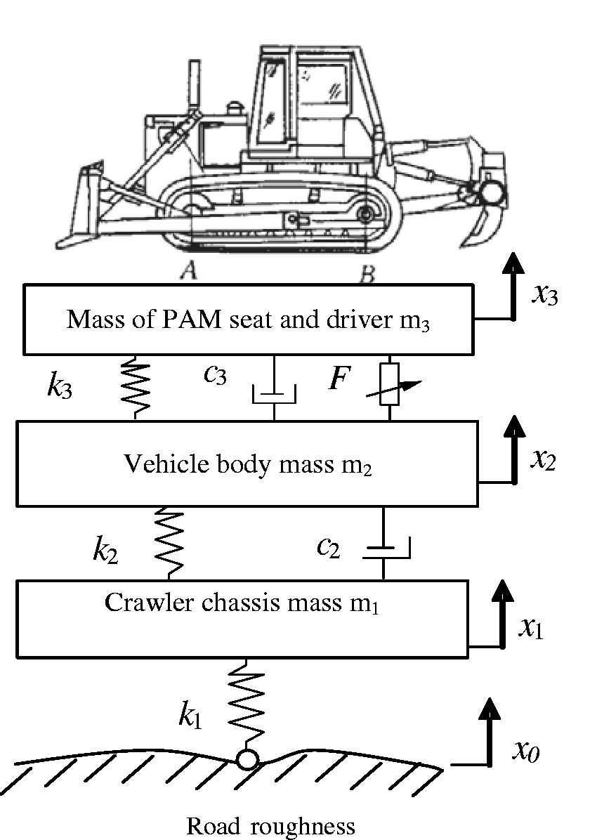
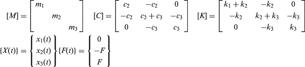
In addition, the following major assumptions are made in the model: (1) Because the vehicle was traveling and working at a low speed, the horizontal loads undertaken by the vehicle body are relatively small compared with the vertical impact force, and they are ignored generally. So the PAM damping seat is considered only to move in the vertical direction. (2) The shape of PAM after expansion resembles an ideal cylinder. Based on the above assumptions and considering the behaviours of the whole system, the governing equations are given in a matrix form as follows

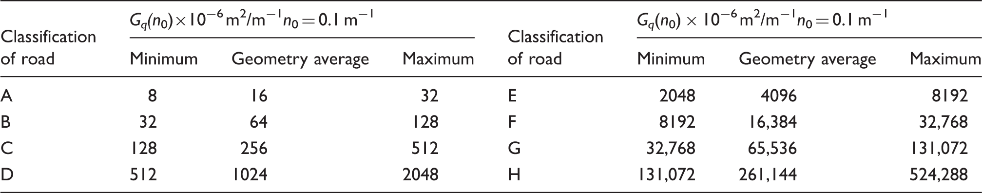
Models of road roughness

Classification of road roughness proposed by ISO 8608-1995.
Vibration characteristics analysis of the PAM damping seat
Numerical simulation
In the simulations, four different roads (C, D, F, G) are chosen to be typical inputs of the vehicle. At the same time, crawler construction vehicles travel forward at a speed of 18 km/h over C-class road, 7.2 km/h over D-class road, 3.6 km/h over F-class road, and 1.8 km/h over G-class road. In addition, two groups of PAM (Festo Corp., model MAS-20-300N) are chosen in the paper. The nominal no-load length of the PAM is about 0.3 m, the un-stretched and un-compressed diameter is 0.02 m, and the initial bias angle is 25°. The maximum permissible contraction is 25% of nominal length. Moreover, the additional maximum load is 1500 N; it could satisfy the vibro-isolating demand of seat used in crawler construction vehicles. The other parameters used in the analysis are: m1 = 640 kg, m2 = 3 × 10⁴ kg, m3 = 95 kg, k1 = 1.2 × 10⁸ N/m, k2 = 1.8 × 10⁷ N/m, k3 = 1.5 × 10⁴ N/m, c2 = 1.2 × 10⁵ N s/m, c3 = 830 N s/m.
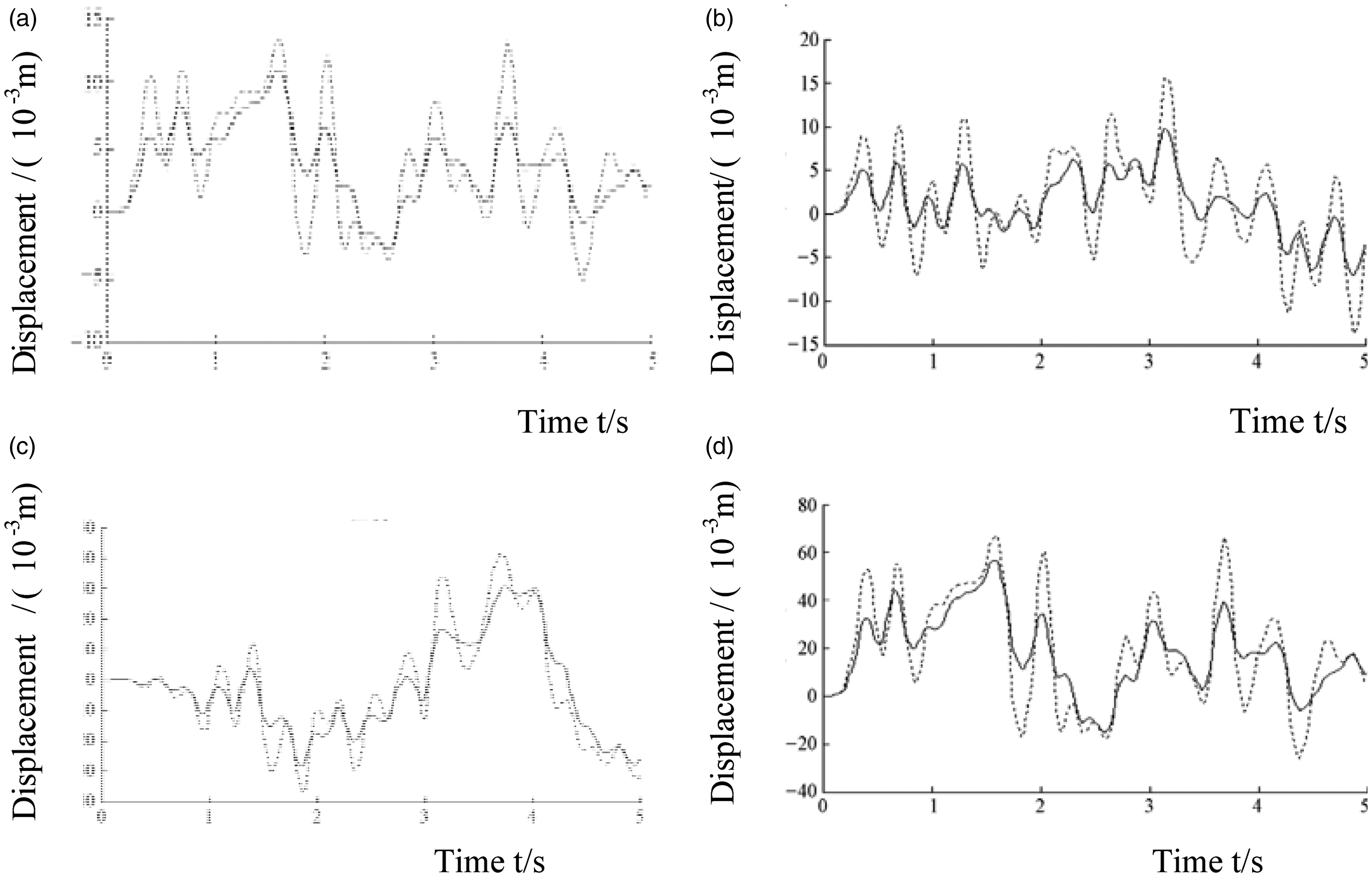
To obtain vibration damping characteristics of PAM seat, Matlab/Simulink is used. Real-time changes of the PID parameters kp–ki–kd under C road are depicted in Figure 7, which indicates parameter-self-adapted features of the fuzzy PID controller. The movement contrasts between the PAM damping seat and conventional seat under four different conditions. Figure 8 shows the comparison of displacement. In Figure 8(a), a crawler construction vehicle is driven at a speed of 18 km/h over C-class road. It may be seen that the reduction of PAM damping seat’s maximum displacement reached 17.4%, the reduction of PAM seat’s minimum displacement was 44.3%, and the standard deviation decreased by 33.3%, compared with those of conventional seat, respectively. From Figure 8(b), a reduction by 37.2% in PAM seat’s maximum displacement, 48.6% in minimum displacement and 39.3% in standard deviation was possible on D-class road with 7.2 km/h speed. In addition, it is noted that the PAM damping seat reduced its maximum displacement compared to the conventional seat by 26.7%, the minimum displacement by 23.2%, and standard deviation by 16.7% on F-class road with 3.6 km/h. Figure 8(d) gives a vertical displacement comparison under the condition of G-class road with 1.8 km/h speed. The reductions in PAM damping seat’s maximum displacement, minimum displacement and standard deviation were 15.0%, 41.5% and 29.8%, respectively.
kp–ki–kd variations of the PAM seat when the fuzzy PID controller is applied under C road: (a) kp variation with time; (b) ki variation with time and (c) kd variation with time. Simulated vertical displacements of PAM (—) and conventional (……) seat: (a) C-class road with 18 km/h speed; (b) D-class road with 7.2 km/h speed; (c) F-class road with 3.6 km/h speed; (d) G-class road with 1.8 km/h speed.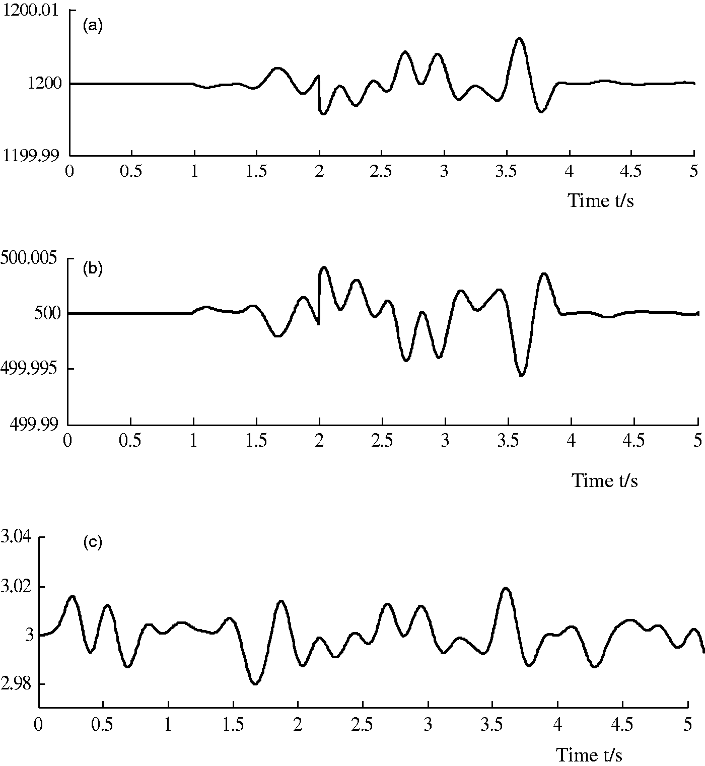
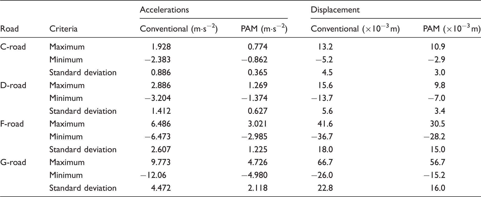
To further analyze the performance of the PAM damping seat, the acceleration responses of the PAM and conventional seats as a function of time are shown in Figure 9. It can be seen that the acceleration difference between the PAM and conventional seat is obvious, the maximum acceleration decreased by 59.9% on C-class road with 18 km/h speed, by 56.0% on D-class road with 7.2 km/h speed, by 53.4% on F-class road with 3.6 km/h, and by 51.6% on G-class road with 1.8 km/h speed, respectively. At the same time, the minimum accelerations obtained under four different operational and road conditions decreased by 63.8%, 57.1%, 53.9%, 58.7%, and the reductions of standard deviation were by 58.8%, 55.6%, 53.9%, 52.6%.
Vertical accelerations simulation of PAM (—) and conventional (……) seat: (a) C-class road with 18 km/h; (b) D-class road with 7.2 km/h; (c) F-class road with 3.6 km/h speed;(d) G-class road with 1.8 km/h speed.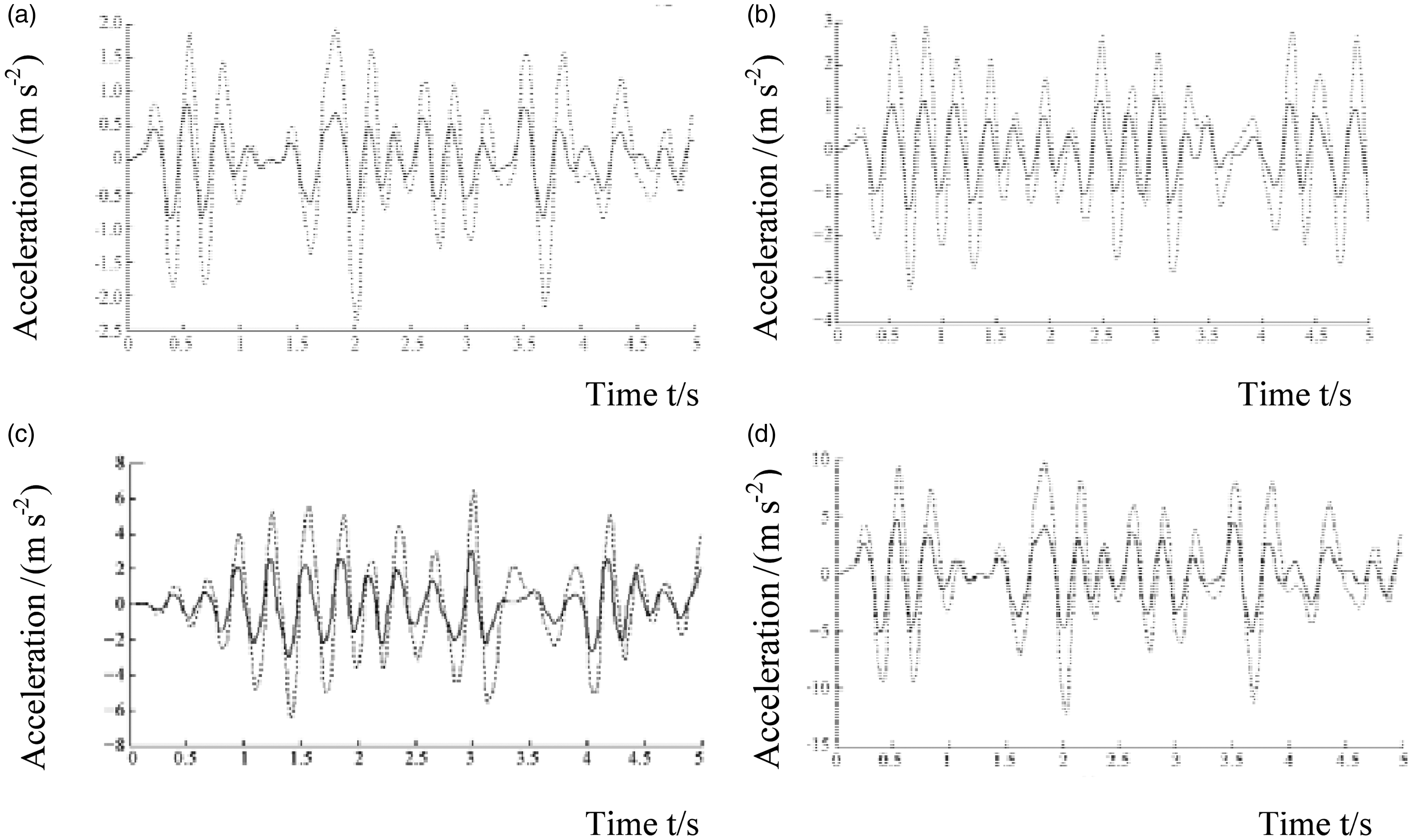
Simulated results of accelerations and displacement.
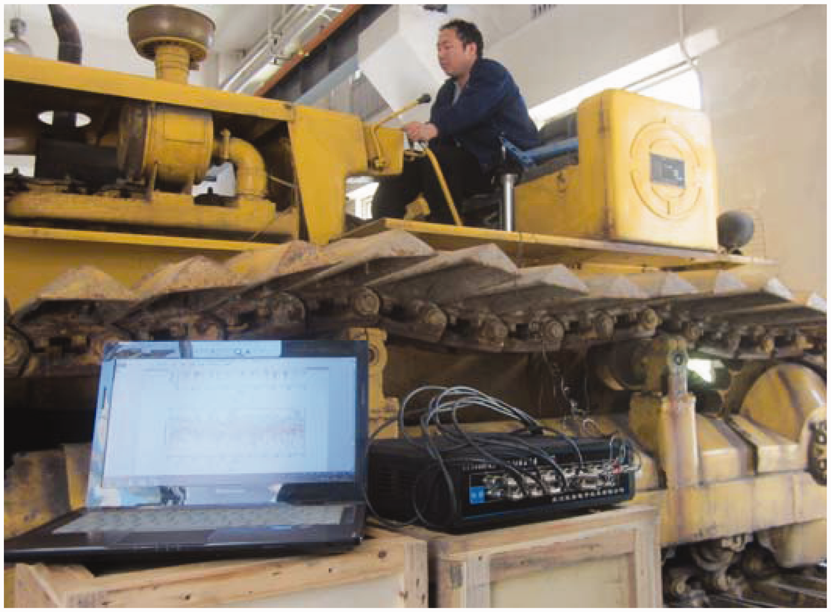
Experiment validity of the seat model
The validity experiment of the seat model was done for the PAM seats under both C and G roads. The experimental setup mainly comprised signal conditioning parts, data acquisition card, a computer, fuzzy PID controller, amplifier and so on, as shown in Figure 10. A photo of actual test is shown in Figure 11.The acceleration signals of seat vibration were acquired using an acceleration sensor. Due to the influence of noise in the process of vibration measurement, a signal filter was connected to the acceleration sensor, thus the acceleration signals would be filtered. At the same time, the vibration of the crawler construction vehicle belongs to a kind of low-frequency vibration, so the low pass filter was adopted to suppress the noise and to ensure the stability and effectiveness of the test acceleration signals.
The experimental set up. The photograph of actual test.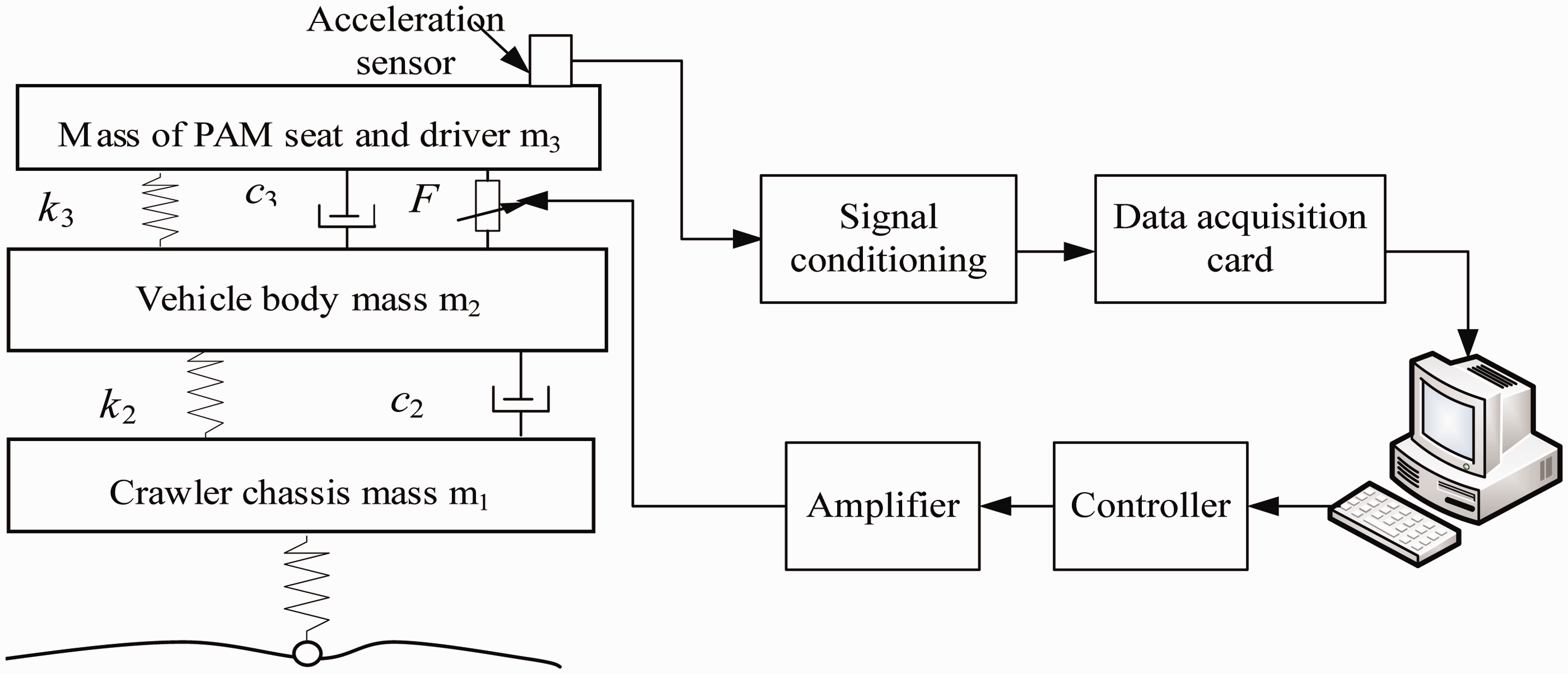
The acceleration response simulation results under two different roads were compared with the experiment data to verify the model, and these are shown in Figure 12. It can be seen that the model simulation results show reasonably good agreements with the experiment data.
Contrasts between the simulation and experiment results: (a) C-class road with 18 km/h speed; (b) D-class road with 1.8 km/h speed.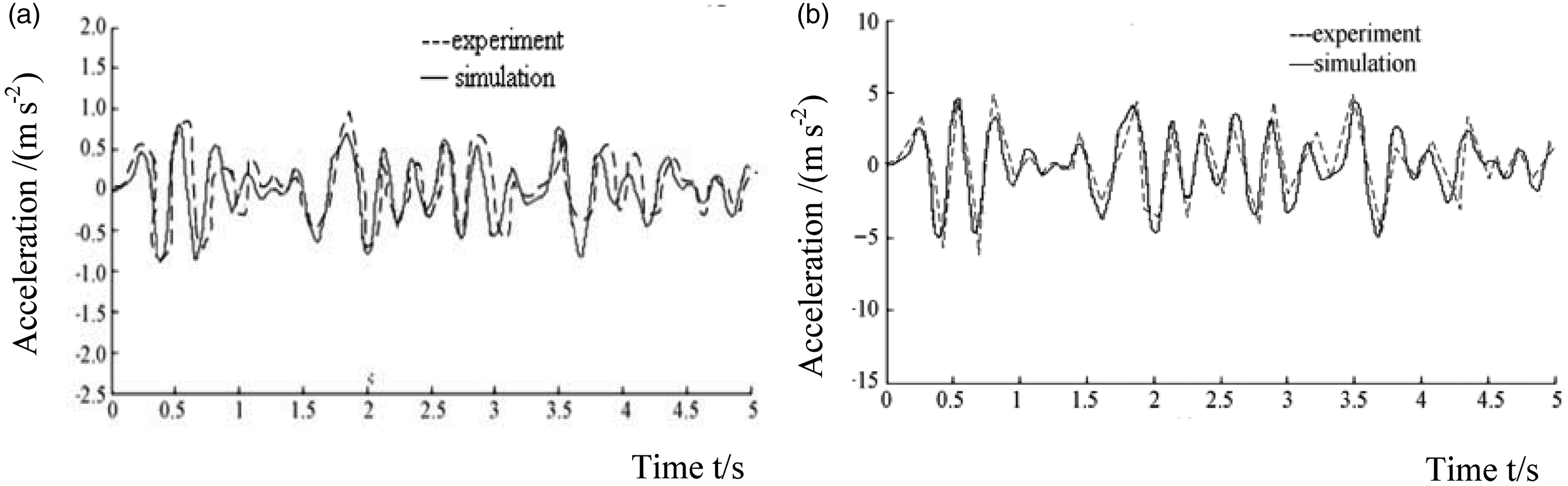
Conclusions
In this research, a PAM damping seat used in crawler construction vehicle has been proposed. The PAM is modelled as a mechanical spring, but it is much more complicated. The movements of two groups of PAM pairs have been controlled by a self-tuning fuzzy PID controller. In order to predict the response of the PAM damping seat due to the road roughness, a simplified 3-DOF model of seat-vehicle body-crawler chassis has been established. Comparisons of vertical acceleration and displacement between PAM damping seat and conventional seat have been made under four different velocity and road conditions using Matlab/Simulink. Simulation results show noticeable vibration reduction effect of the PAM damping seat. The experimental data acquired have confirmed the correctness of the analytical model. Thus, the research results can provide references for the application of PAM in seat.
Footnotes
Declaration of conflicting interests
The author(s) declared no potential conflicts of interest with respect to the research, authorship, and/or publication of this article.
Funding
The authors would like to thank the support by National Natural Science Foundation of China (Grant No. 51405323) and Shanxi Scholarship Council of China (Item No.2012-073) and the Taiyuan University of Science and Technology Foundation for Doctor (Item No. 20132002) for this project.