
Abstract

It was October 11, 2012. A quarterly performance review meeting for the third quarter (Q III) was going on in the conference hall of Delta Engines Limited (DEL). Vighnesh Reddy, General Manager (GM) of the Machining Department, was reviewing the performance of all the departments under him. After a satisfactory performance review of the Engine Auxiliary Machining Department (EAMD) and the Engine Component Machining Department (ECMD), it was the turn of the Engine Frame Manufacturing Department (EFMD) to present its performance report.
Everyone present in the meeting, including the GM, was highly optimistic and expected a significant increase in the output levels. However, contrary to their expectations, the performance review of EFMD revealed that the production level for Q III had gone down by 2.5 per cent compared to the levels for Q I and Q II of the current financial year. (Refer to Exhibit 1 for production details.) Disappointed and infuriated, Reddy told Gagan Dixit, Head of EFMD, to find a solution within seven days and ensure an increase in the production level.
COMPANY BACKGROUND
Delta Engines Limited, an Indian diesel engine manufacturing company, with headquarters in Chennai, Tamil Naidu, had established itself as one of the leading diesel engine-manufacturing firms in India. Various earth-moving equipment-manufacturing companies like Alpha Motors and Beta Earth Movers used engines manufactured by DEL.
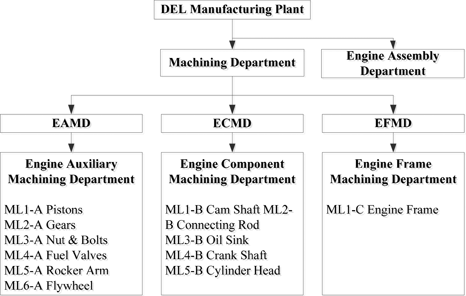
The manufacturing facilities at Chennai were distributed in two main departments, namely, Machining Department and Engine Assembly Department. The Machining Department was further subdivided into three departments, namely, EAMD, ECMD and EFMD. (Refer to Exhibit 2 for departmental structure.) EAMD manufactured auxiliary components of the engines like pistons, gears, nuts and bolts, fuel valves, rocker arm, and flywheel. ECMD produced critical components of the engine like camshaft, connecting rod, crankshaft cylinder head and oil sink, whereas EFMD produced the most important and critical part of the engine—the engine frame—on which all the auxiliary components, critical components and other standard components were mounted. All these machining departments had separate and dedicated ultramodern critical machining lines for individual products. For example, EAMD, producing six components, had six dedicated machining lines; similarly, ECMD had five dedicated machining lines while EFMD had only one machining line. All of these machining lines had Japanese computerized numerically controlled (CNC) machining centres and various other conventional and non-conventional machines arranged in the sequence of operations for providing outstanding performance. These machining lines received raw materials in the form of rough castings or forgings and converted them into finished components. Components produced in EAMD, ECMD, and EFMD were finally sent to the Engine Assembly Department for final assembly and testing on the rated parameters. Even a slight deviation in the rated parameters of the final engine could result in the rejection of the engine.
Production Details
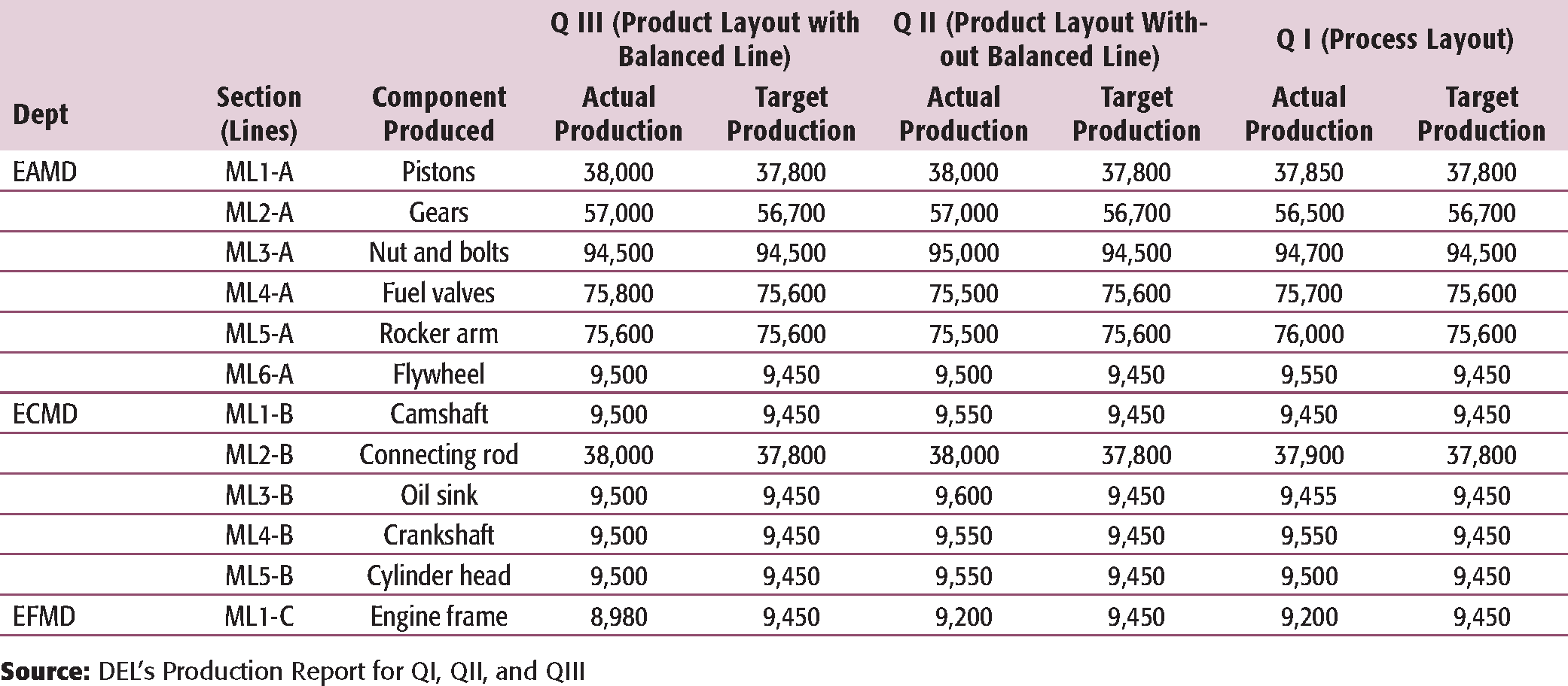
DEL's Production Report for QI, QII, and QIII
IDENTIFYING THE ACTUAL PROBLEM
Two years ago, DEL had hired Gagan Dixit—who worked as a Senior Manager in component-machining department of a top Fortune 500 manufacturing firm—as the head of the most critical machining line—EFMD. After joining DEL, he thoroughly assessed the entire EFMD machining line and recommended to change the factory layout from process layout 1
A layout that groups similar activities together. For instance, milling department, drilling department, etc.
In the product layout, activities are arranged in a sequential manner.
Reddy decided to follow Dixit's recommendation and told him to schedule the factory layout transformation activity for Q II. Accordingly, Dixit planned and completed the layout transformation activity before the beginning of Q II. However, to his surprise, he did not observe any increase or decrease in the monthly production in the first month of the second quarter. During his visit to the shop floor, he noticed that some machines were continuously running and inventory was piling up in front of these machines while some other machines were idle and were waiting for jobs. Even in the next round of visit, he did not find any change in the situation. This made it clear that factory layout was not the actual problem; the underlying problem lay in the unbalanced production line. Dixit, thus, concluded that balancing of the existing machining line would solve the problem of inefficient capacity utilization of the machines and the consequent overall underproduction. Once again, he approached Reddy and sought permission for line balancing. Reddy allowed Dixit to balance the production line with the hope that he would equalize the machine utilization and increase the production level. Dixit completed the task of line balancing in the stipulated time and once again assured Reddy that the output would increase for Q III. However, the production report for Q III revealed that the production level had actually gone down by 2.5 per cent, thereby indicating that balancing the production line was not the correct decision. This created tension in the boardroom.
LOOKING FOR A SOLUTION
Getting a Grip on the Problem Through Discussion
Dixit approached Shailesh Soni, a friend in his previous organization, for his expert advice for improving the production level. Next day, when Soni came to visit the plant, Sanjeev Raghu, Manager, EFMD, was told to describe the working of the department.
Raghu started explaining:
We are producing the most important and critical part of the engine, that is, the engine frame. As all the other components of the engines are mounted on the frame, it is very important for us to maintain the accurate dimensions. Any slightest deviation in the dimensions causes a problem in fitting the other components of the engine, which ultimately results in greater variation in the rated parameters of the engines like output power, torque, high speed, etc. Such kind of deviation in parameters is unacceptable to our customers. Over the years, we have continuously improved our processes in a way that the rejection rate of the final components has gone down to 0.53 per cent in our final inspection stage and to 0.03 per cent in the assembly section. The quality initiative at our department has fetched four national level quality awards in the past two years. So, we are proud of our department and enjoy working here.
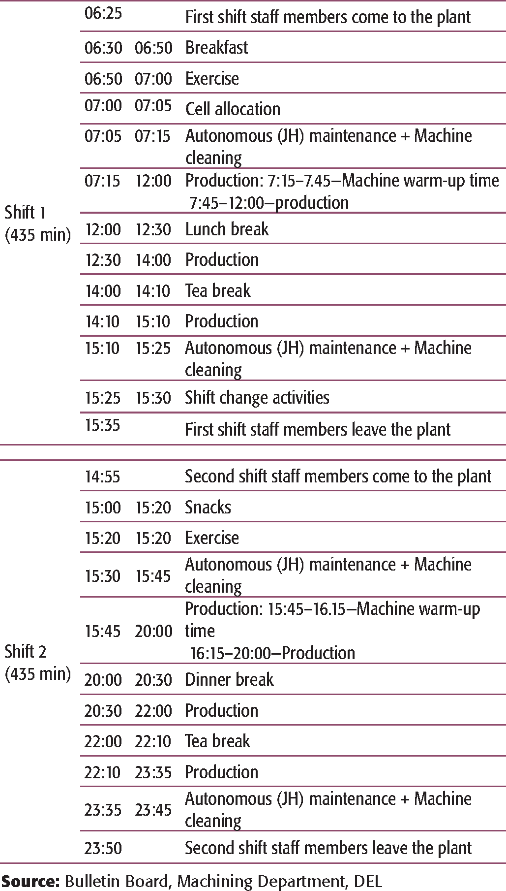
Shift Schedule (July 2012-September 2012)
Further, he added:
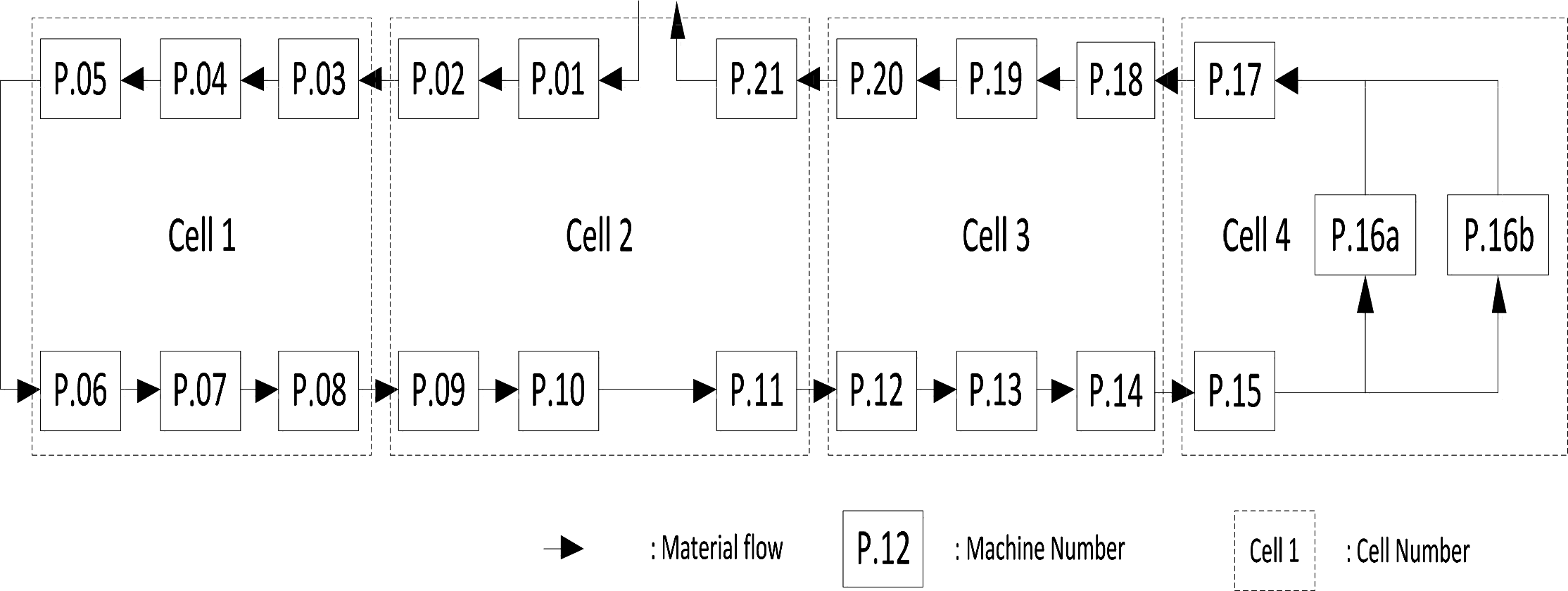
The EFMD machining line, operating in two shifts [refer to Exhibit 3 for detailed shift schedule], comprises 22 ultramodern Japanese automated CNC machines arranged in the shape of the letter ‘U'. [Refer to Exhibit 4 for the layout design saving on workforce per machining line and space requirement.] Only four operators and two assistant operators manage the entire line. Each operator is assigned a cell, and the two assistant operators perform various supporting tasks like tool changing, fixture aligning and restoring breakdown machines in order to run the machining line smoothly.
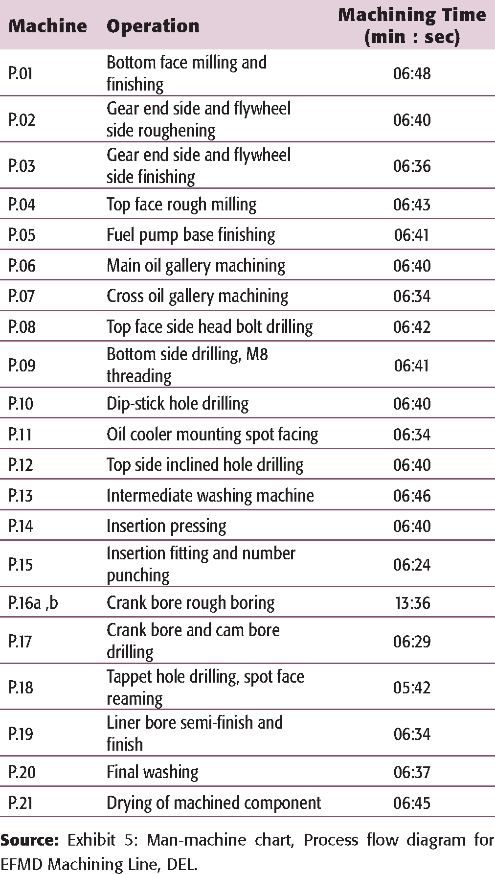
An automated feeding conveyor system places the engine frame casting at the input side of the machine P.01. The operator of cell no. 2 sends that casting to machine P.01 and after machining it, he sends the machined work-piece to the next machine P.02. In a similar fashion, all the work-pieces are transferred to the respective next machines for processing. As the machining time for the 16th machine is almost double of the machining time for other machines, two machines (P.16a and P.16b) are used in parallel to reduce the effective machining time to half and for balancing the line. After that, once again, the line merges into a single line as before P.17, reaming operations are performed, followed by a quality inspection after P.21 [refer to Exhibit 5 for machining sequence and machining time 3
Total machining time comprises actual machining time required plus 50 seconds of loading and unloading operation.
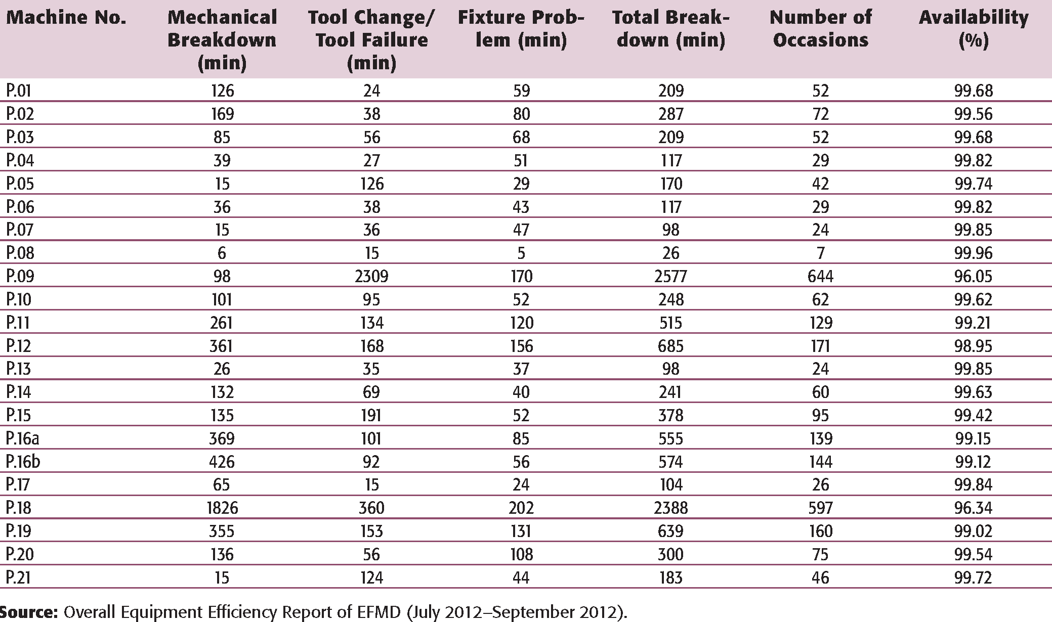
In an ideal condition, there should not be any breakdown and machining line should be able to produce an engine frame in 6.8 minutes, that is, 64 engine frames in a shift of 435 minutes. However, frequent breakdowns are observed due to mechanical failure, low lubricant oil level, tool change, tool failure and fixture problems. [Refer to Exhibit 6 for detailed breakdown structure.] Whenever such kind of breakdown occurs, operators and assistant operators have to attend to the broken-down machine and restore it. Normally, it takes 4 minutes to restore the machine, yielding in a loss in the production time.
Considering 95 per cent overall equipment effectiveness (as calculated by operators), machining line should produce 61–62 engine frames in a shift, but it is actually producing only 57–59 engines.
Machining Sequence
Breakdown Summary for Q III (July12 to September 12)
Total production time = 75 days × 2 shifts/day × 7.25 hours/shift = 1087.5 hrs
When Soni asked Raghu about Dixit's view on low production, he said: ‘According to Dixit Sir, operators are new to the system, and so are not able to produce at the expected rate. He thinks that over time output will increase.'
Immediately, Soni approached one of the operators and tried to understand the problems faced by them. The operator replied:
Earlier in process layout, whenever a machine broke down, the assistant operator restored the broken-down machine in 7–8 minutes. During that time, the operator worked on other machines. After restoring the machine, the operator had the flexibility to work independently on the broken-down machine and reduce the backlogs and piled-up inventory. However, in the present structure, the operators and the assistant operators have to work together to restore the breakdown machine. This has resulted in the reduction of restoration time from 7–8 minutes to 4 minutes; however, no production takes place in these 4 minutes. This results in starvation of its downstream machines resulting in one or more idle cycle/s spreading to all other downstream stations and blockages of upstream lines. On the other hand, if the operator decides to utilize these 4 minutes for production, he faces blockage at the broken-down machine because of unavailability of buffer spaces between the two machines. This kind of arrangement has resulted in a drop in the total output per shift. Another reason could be the difference in time taken by the operators to unload the job from machine and load it to the machine. But loading and unloading being a standard process, there should not be any significant change due to the layout change.
With these inputs from EFMD, Soni went to Dixit's office and asked him to give him a day to fix the problem.
Considering the overall situation, how can Soni help Dixit increase the output of the machining line? Was it appropriate to balance the production line in this case? Will an increase in the output rate of EFMD machining line lead to an increase in the total output of DEL?