
Abstract
The introduction of image guidance in radiation therapy and its subsequent innovations have revolutionised the delivery of cancer treatment. Modern imaging systems can supplement and often replace the historical practice of relying on external landmarks and laser alignment systems. Rather than depending on markings on the patient’s skin, image-guided radiation therapy (IGRT), using techniques such as computed tomography (CT), cone beam CT, MV on-board imaging (OBI), and kV OBI, allows the patient to be positioned based on the internal anatomy. These advances in technology have enabled more accurate delivery of radiation doses to anatomically complex and temporally changing tumour volumes, while simultaneously sparing surrounding healthy tissues. While these imaging modalities provide excellent bony anatomy image quality, magnetic resonance imaging (MRI) surpasses them in soft tissue image contrast for better visualisation and tracking of soft tissue tumours with no additional radiation dose to the patient. However, the introduction of MRI into a radiotherapy facility has a number of complications, including the influence of the magnetic field on the dose deposition, as well as the effects it can have on dosimetry systems. The development and introduction of these new IGRT techniques will be reviewed, and the benefits and disadvantages of each will be described.
1. History of Image Guidance
Radiation therapy for cancer treatment, unlike most other cancer treatment modalities, is a precise and extremely quantitative modality. Unlike surgery, where the target tissue must often be exposed so as to be visible to the surgeon, radiation therapy is largely non-invasive and requires means other than the physician’s vision to guide the radiation beam. The identification of the target tissue is critical because, as was stated by the physicist Harold Johns, ‘if you can’t see it, you can’t hit it, and if you can’t hit it, you can’t cure it’ (Njeh, 2008). Early radiation therapy therefore relied on the physician’s best estimate of tumour location, and skin markings made through the use of x-ray imaging systems (Tousey, 1910; Hendee et al., 2005).
Early radiation therapy treatment guidance consisted of x-ray imaging prior to the treatment using conventional x-ray imaging equipment. Beginning in the 1970s, dedicated radiographic and fluoroscopic equipment was assembled to simulate the geometry of a treatment unit. Before long, such radiation therapy simulators were standard equipment in therapy departments. Also in the 1970s, ultrasound imaging was introduced, which provided, for the first time, the ability to identify organs and, in some cases, tumour boundaries. Fairly extensive use of ultrasound was made for planning radiotherapy to the prostate (Brascho, 1977). At the same time, computed tomography (CT) scanners were becoming available in radiology departments, and their use for radiation therapy treatment planning was quickly recognised (see Fig. 1) (Chernak et al., 1975). The geometric fidelity of early CT scanners was quite poor by today’s standards, and corrections often had to be made for distortion (Ibbott, 1980; Ragan et al., 1993). In most institutions, access to a CT scanner was very limited, as their use for diagnosis was also expanding rapidly. Improved methods for acquiring external contours of patients for computerised treatment planning were found in the meantime (Hills et al., 1979). As a way to make cross-sectional images available for treatment planning, fluoroscopic simulators were adapted to acquire tomographic data during a rotation of the simulator gantry, so that a simple single-slice CT scan could be obtained. The quality of these images was relatively poor, but improved detector systems ultimately led to much better quality imaging. However, the availability of CT scanners was increasing rapidly, and brought the opportunity to format three-dimensional (3D) image data sets in arbitrary planes, including views that mimicked the images produced by ‘conventional’ simulators (Goitein et al., 1983). Software for CT-based radiation therapy simulation became available, and was once known as ‘virtual simulation’ (Nishidai et al., 1990; Rosenman et al., 1991; Sherouse and Chaney, 1991). By the early 21st century, conventional simulators had largely been replaced with dedicated CT scanners.
One of the first demonstrations of the use of computed tomography (CT) images for treatment planning. (A) CT scan of the head and neck showing a carcinoma of the right antrum. Note: these images are displayed with the patient’s right to the viewer’s right. (B) ‘Density scanning presentation’, the results of computerised edge detection. (C) Calculated isodose distribution for a wedged pair of fields. Source: Chernak et al. (1975), reproduced with permission.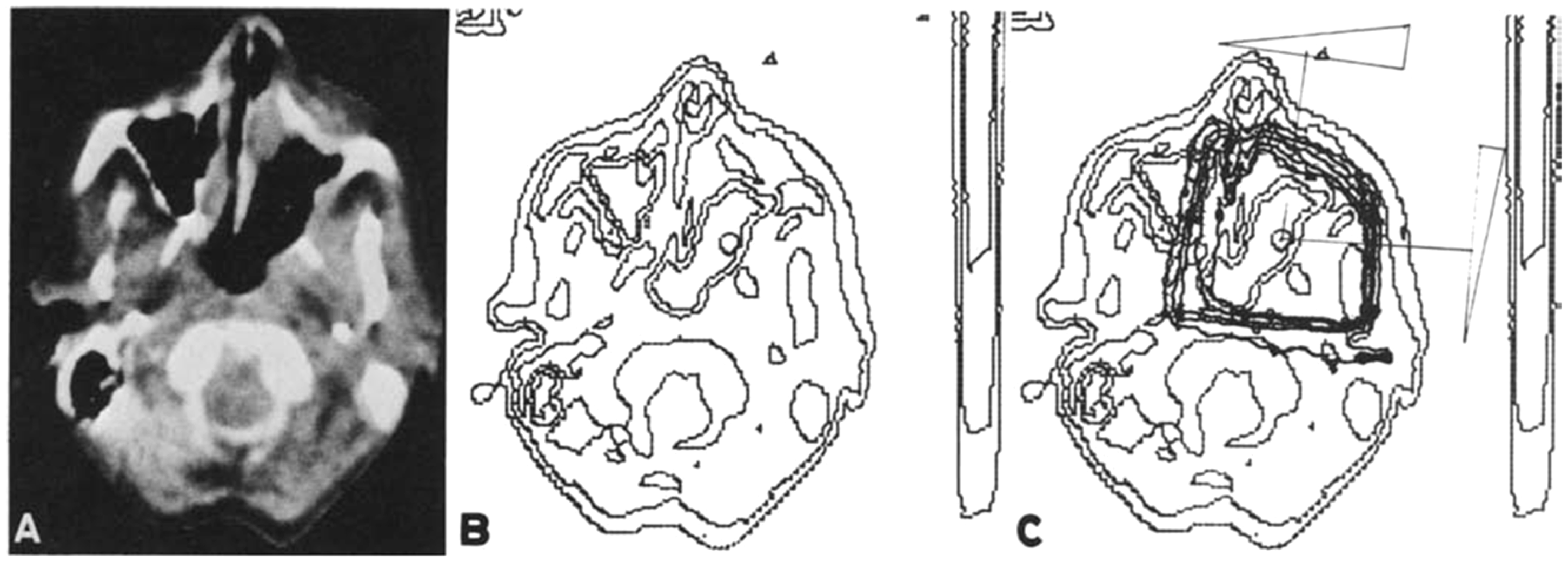
Throughout this period, patients were prepared for treatment by identifying the target with the simulator or CT simulator, and registering the patient’s position through the use of ink marks on the patient’s skin. The patient was then moved to the treatment unit; at that time, either a 60Co teletherapy unit, an electron linear accelerator, a betatron, or – in a few institutions – a particle-beam accelerator and the skin markings were aligned with a laser system mounted to the walls of the treatment room. In this way, the target volume was presumed to be aligned with the reference point or ‘isocentre’ of the treatment machine. The correct positioning of the patient could be verified by placing radiographic film behind the patient and exposing the film with the treatment beam. These ‘localisation films’ or ‘portal films’ had to be developed; therefore, rather than delay treatment, the treatment was often delivered and, if adjustments were found to be necessary, they were made before treatment the next day. If adjustments were to be made on the same day, the patient had to wait on the treatment table until the films could be reviewed by the physician, adjustments made, and sometimes verified a second time before treatment was delivered. A key feature of virtual simulation software was the ‘digitally-reconstructed radiograph’ (DRR), a simulation of a projection image that could be compared with a portal image to assist in determining whether adjustments were needed.
A major step forward came with the introduction of electronic portal imaging detectors (EPIDs). EPIDs consisted of two-dimensional (2D) arrays of semiconductor detectors that captured a portal image electronically, replacing radiographic film and the need for a film developer. These devices became available in the 1990s, but the technology improved substantially in the early 21st century, yielding EPID images of higher quality than the portal films they replaced. Manufacturers began shipping linear accelerators equipped with EPIDs, and by 2000, most linacs were delivered with this equipment. Two important results were that the images were available almost instantly after exposure, and they could be compared digitally with the DRRs produced by the CT simulator. This milestone allowed true adaptive therapy, meaning that the treatment could potentially be modified to account for variations in the patient’s position on a daily basis. Many clinics today use this technique to adjust the patient’s position based on a comparison between EPID images and DRRs from the planning system (2D/3D matching) (Jaffray et al., 2007; Munbodh et al., 2008).
At the same time, linac manufacturers began to mount on-board kilovoltage (kV) imagers on the gantries of their systems, so that almost diagnostic-quality orthogonal radiographs could be obtained of the patient in the treatment position by rotating the gantry. These imaging systems facilitated the comparison of projection radiographs from the on-board imaging (OBI) system with DRRs, leading to vastly improved 2D/3D matching (Markelj et al., 2012) Two implementations of kV-image guidance have been developed that fix the x-ray sources and imaging panels in the treatment room, rather than mounting them on the gantry of the treatment device. The first of these, developed and marketed by Accuray (Sunnyvale, CA, USA), is part of the CyberKnife robotic treatment delivery system. Cross-firing kV-imaging systems are mounted on the floor and ceiling of the treatment room, and images of the patient can be taken at regular intervals before and during treatment. The images are compared with DRRs reconstructed from the planning CT, and displacements can be detected by software. A similar system, the ExacTrac, was developed and is marketed by BrainLab (Jin et al., 2008). The BrainLab system can be installed with any linac, or can be delivered as part of the Novalis conventional 6 MV linac.
At this point, there was a revival of the proposal from years earlier to create CT images by acquiring transmission data from a portal imaging system, but instead using the kV OBI system. Rather than obtaining a single slice of information, the device could use the entire area of the flat-panel image receptor (Jaffray et al., 1999, 2002). CT volumetric image data sets obtained from the projection beam of a kV source are known as cone beam CT (CBCT), and their use has enhanced image-guided radiation therapy (IGRT) considerably (Thilmann et al., 2006; Moseley et al., 2007; White et al., 2007). It is likely that the radiation oncology community has not yet fully exploited the potential of CBCT in image guidance. The availability of a full 3D data set from the patient while in the treatment position allows for a 3D/3D comparison with the reference CT data set, generally obtained at the time of CT simulation. Alternatively, a daily set of orthogonal projection images could be compared with a reference CBCT image of the patient, leading to the potential for simulation and treatment on a single device (Munbodh et al., 2006).
2. Evidence for Clinical Benefits of Image Guidance
From the early days of radiation therapy, it was recognised that patients changed over the course of treatment. Interfraction changes occur at infrequent intervals; these may be a result of tumour regression in response to treatment, or perhaps growth in spite of treatment. Some patients lose weight during treatment, often as a result of an aversion or inability to intake adequate nutrition. During the previous century, this was most often addressed by scheduling a modification to the treatment at two-thirds or three-quarters of the way through the course. Very often, this was in the form of a reduction in treatment field dimensions, anticipating reduced tumour volume by that point in the treatment. Before the availability of CT scans, such field size reductions were based on very limited clinical data.
Interfraction changes also result from variations in patient position from one treatment fraction to the next. Some such changes are unavoidable; although flat table tops are customary in radiation therapy, some anatomical regions, particularly the head, require the use of positioning aids of some sort to help assure reproducible positioning. Other changes result from non-compliance with instructions from the therapy staff. Frequently, these are understandable; on the first day or two of treatment, patients are sometimes apprehensive and may tense muscles that they are able to relax on subsequent treatment occasions.
Intrafraction changes, as the name implies, take place on a shorter time frame, and refer to patient motion due to respiration, peristalsis, and cardiac motion, as well as short-period movements such as coughing, muscular spasms, wriggling, etc.
An example of a dilated rectum at the time of simulation, and marked reduction in diameter a week later at the start of treatment. The superimposed contours demonstrate the inadequacy of the original treatment plan when registered to the bony anatomy from the subsequent computed tomography scan.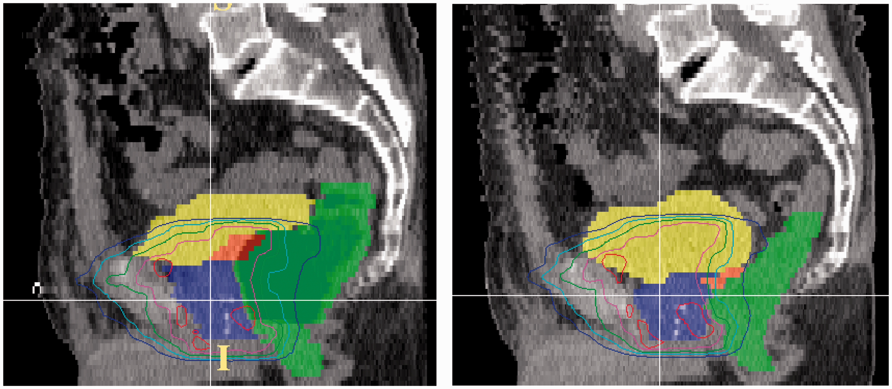
During most of the last century, such variations in patient position were managed by increasing the treatment field size to ensure that the target volume remained within the high-dose region. In the case of respiratory motion, this could mean increasing the cranio-caudad dimension of the field by 2–4 cm, resulting in a substantial increase in irradiated normal lung.
The recent availability of IGRT systems has enabled radiation oncology teams to address both inter- and intrafraction motion much more effectively. Evidence that image guidance has contributed increasingly to treatment management is suggested by a rapid increase in the number of publications mentioning stereotactic radiation treatment and its variants, for which image guidance is a prerequisite.
A number of publications have reported improvements in radiation therapy outcomes as a result of incorporating image guidance. An early example was reported by de Crevoisier et al. (2005), who demonstrated that the dilation of the rectum at the time of simulation correlated with increased biochemical failure in treatment of prostate cancer (see Fig. 3).
Freedom from biochemical failure for patients with different rectal diameters at the time of simulation and planning. A significant improvement is seen in patients whose rectal diameters were <6 cm at the time of simulation compared with those whose rectal diameters were ≥6 cm. RT, radiation therapy. Source: de Crevoisier et al. (2005), reproduced with permission.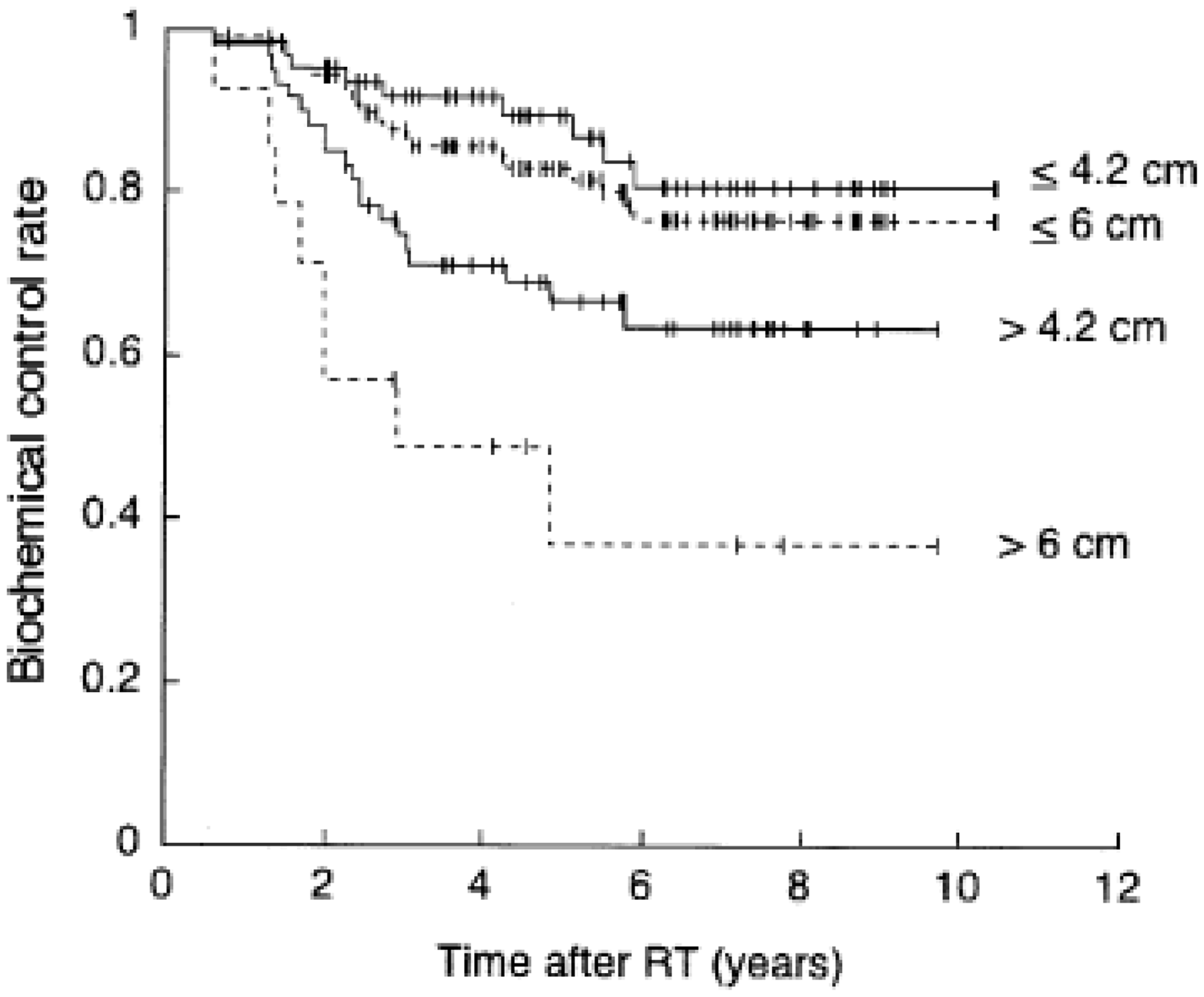
De Crevoisier et al. (2005) considered only the appearance of the anatomy at the initiation of treatment. An important consideration is that kV orthogonal imaging and rigid registration of bony anatomy would not have improved the outcome of this series of patients. However, a study by Berlin et al. (2015) reported reduced bladder and rectal toxicity with no reduction in biochemical outcome in a series of prostate cancer patients treated using CBCT-based IGRT.
Kilburn et al. (2016) reported improved local control in patients with locally advanced lung cancer when IGRT was used (see Fig. 4). This study of 169 patients also compared the characteristics of treatment when IGRT was used, and found that patients were more likely to receive a higher tumour dose than when IGRT was not used (median doses of 70 Gy and 66 Gy, respectively; 99% received ≥60 Gy when IGRT was used, only 91% received ≥60 Gy when IGRT was not used). Presumably, radiation oncologists were more comfortable delivering higher doses when smaller target volumes could be identified, because correspondingly smaller volumes of normal lung received biologically significant doses.
Kaplan–Meier estimates of local and locoregional failure-free survival in patients receiving image-guided radiation therapy (IGRT) and non-IGRT treatments. Source: Kilburn et al. (2016), reproduced with permission.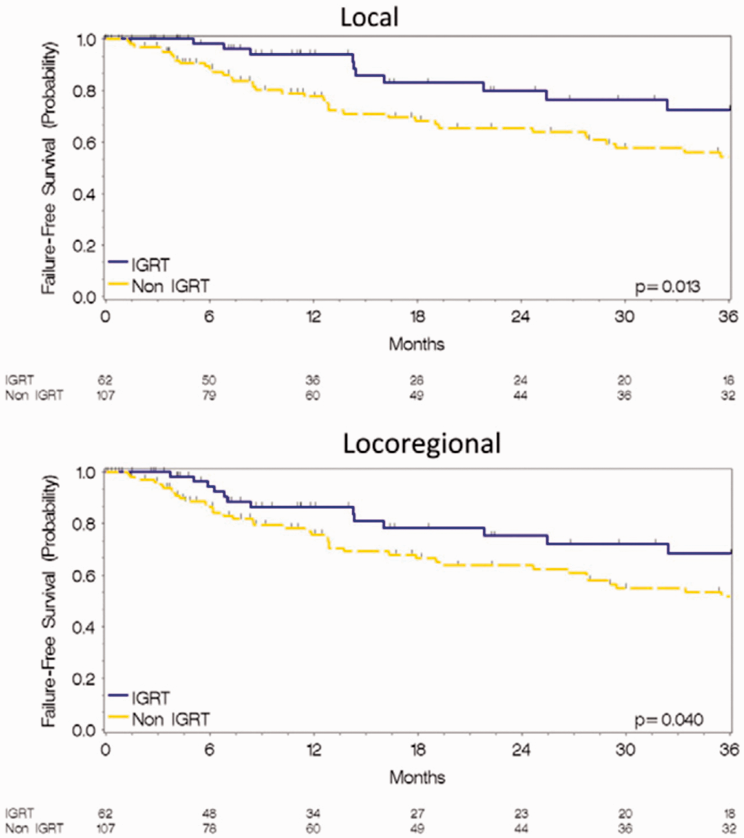
3. POTENTIAL DISADVANTAGES OF IMAGE GUIDANCE
The use of kV (or MV) imaging for treatment guidance has potential deleterious effects resulting from additional radiation exposure. Cheng et al. (2017) estimated the dose from imaging. While it is recognised that, in general, the dose from imaging is far smaller than the dose from the radiation therapy itself, the volume irradiated by imaging systems is generally far larger, and likely to include sensitive normal tissues such as the lens of the eye, the breasts, and the bowel. Although the dose from individual kV planar images or CBCT scans is relatively low, the use of daily image guidance can result in the dose over a course of treatment being significant in terms of biological effects (Hall and Wuu, 2003). Consequently, the benefits of x-ray-based IGRT should be weighed against possible detriment to the patient.
There is no question that the equipment required for image guidance adds to the cost of a radiation therapy unit. It is not easy to estimate the cost in terms of time or intensity of IGRT; however, imaging with an EPID is generally much faster than waiting for a film processor, and the confidence in patient positioning is considerably greater.
4. Contemporary IGRT Techniques
Today’s IGRT technologies are largely refinements of the devices and methods developed over the past several decades. Several institutions have reported good results through the use of CT scanners mounted on rails in the treatment room. These facilities allow acquisition of a CT scan of the patient while on the treatment table, immediately prior to treatment. In the example of the rectal diameter study mentioned above, such pretreatment CT imaging would have demonstrated changes in the rectal diameter and the position of the prostate, and might have allowed for adjustments to be made before treatment. CBCT systems can potentially provide similar pretreatment imaging for some anatomical regions, although CBCT image quality is inferior to that from a diagnostic CT-on-rails system, and would not provide an adequate substitute.
The availability of a CT image data set at the time of treatment allows for more comprehensive 3D/3D matching with the reference CT-based treatment plan for the patient. Rather than relying on rigid registration of bony anatomy, techniques are now available and in use at many centres for deformable image registration (Brock et al., 2006). This software facilitates a more realistic comparison between daily images and the reference images, recognising changes to the patient’s anatomy, and deformations in the size and shape of the tumour as well as surrounding normal organs.
Until recently, wide use was made of an ultrasound system that could also demonstrate the position and shape of the prostate as part of patient positioning for treatment (Brascho, 1977). Improved results were shown when this system was used (Molloy et al., 2004). Time-of-flight cameras and sophisticated surface-mapping techniques have been used to aid in patient positioning (Gilles et al., 2016). While these systems cannot demonstrate changes in internal anatomy, they can be very useful when the external surface is an adequate surrogate of target volume position, as can be the case in head and neck and breast cancers.
However, MV and kV images provide poor soft tissue contrast and rely largely on bony anatomy for patient positioning, imposing a requirement that the tumour does not move relative to the bony anatomy. To provide greater assurance of correct target location, some facilities have implanted radiographic markers into the target volume. An extension of this technique employs electromagnetic transponders that can be implanted and interrogated by an external antenna (Colvill et al., 2015).
Management of respiratory motion presents a difficult problem in radiation therapy. X-ray-based OBI systems cannot resolve soft tissue anatomy adequately to demonstrate the tumour unless it is of sufficiently different density from the surrounding tissue, as can be the case for some lung tumours. However, even when the tumour can be visualised with systems such as CBCT, the slow acquisition time of these devices makes their use for monitoring respiratory motion impractical. A few x-ray-guided treatment systems, such as the CyberKnife, are able to track intrafraction motion, although some require the use of implanted fiducials. Other systems rely on the motion of a surrogate structure, and develop a correlation model to predict tumour motion (Starkschall et al., 2011).
5. Advanced and Proposed Techniques for IGRT
5.1. MRI-guided radiation therapy
A major recent advance has been the introduction of magnetic resonance imaging (MRI) into radiation therapy. While MRI has been used for some time to contribute to the identification of tumour volumes and organs at risk, it is only recently that MRI has been considered for treatment guidance. For a variety of reasons, but primarily the improved soft tissue delineation offered by MRI, this modality seems destined to dominate the field of IGRT for the immediate future (Pollard et al., 2017). MR offers not only superior soft tissue contrast but also functional imaging (at 1.5 T and above) and the possibility of imaging during treatment to monitor patient motion.
A description of an MR-guided linac was first published by Lagendijk and colleagues, which presented a proof-of-principle demonstration of the concept (Lagendijk and Bakker, 2000; Lagendijk et al., 2002). Subsequent work by this group led to the development of a collaboration with Philips and Elekta and the construction of the MR-Linac (Elekta AB, Stockholm, Sweden), with preclinical systems currently installed under research agreements at seven institutions around the world. This system combines a 1.5 T Philips MR imager with a 7.5 MV Elekta linear accelerator (see Fig. 5).
The Elekta magnetic resonance (MR)-Linac showing the linear accelerator mounted on a circular gantry around the Philips MR imaging system. Reproduced courtesy of Elekta. MLC, multileaf collimator.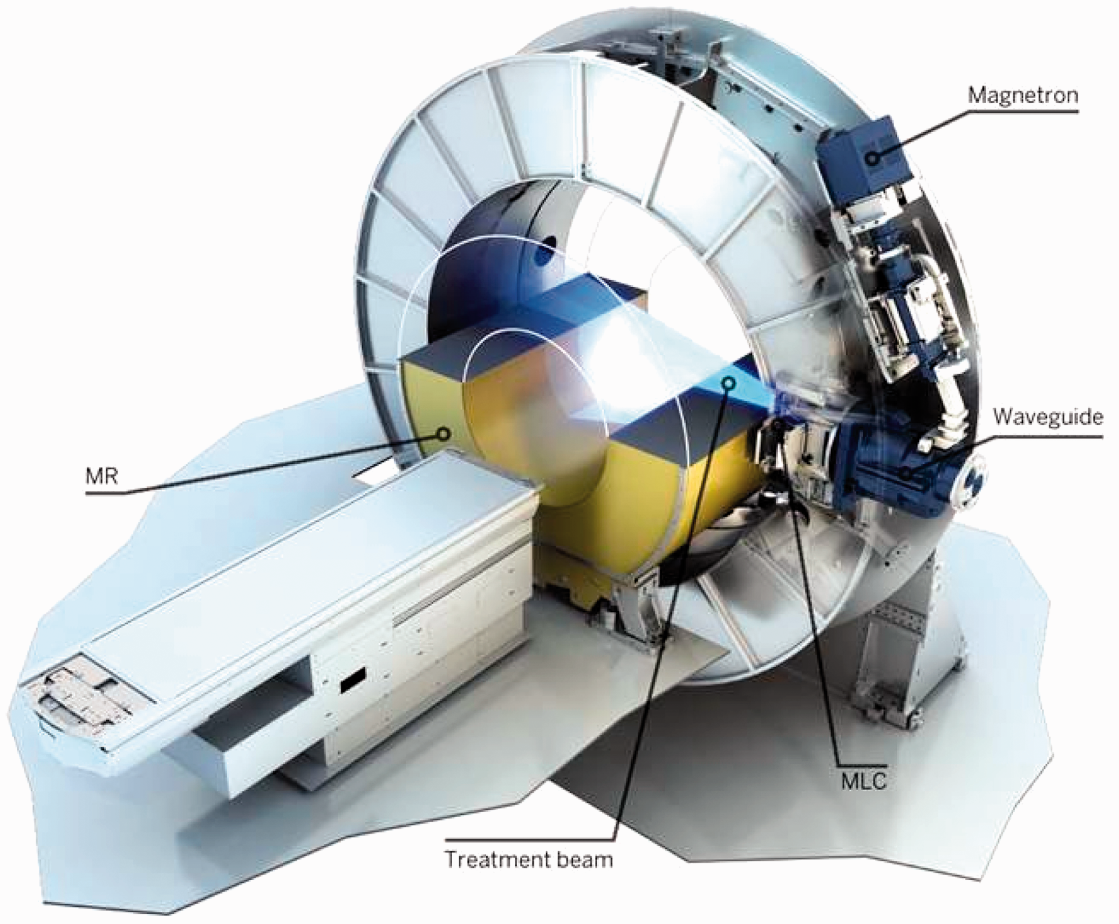
The magnetic field of MRI can exert a Lorentz force on electrons set in motion through photo-electric or Compton interactions of MV photons in tissue. In the absence of a magnetic field, such secondary electrons undergo a series of many collisional and radiative interactions with atomic electrons and nuclei, following a random path made up of short, straight trajectories within the tissue. In the presence of a magnetic field, these forces change the straight trajectories into curved paths, resulting in a shortening of the overall path and a preferential directional change. At greater magnetic field strengths, these effects become more pronounced. Where the secondary electrons emerge from tissue into a lower-density medium such as lung or air, their paths can be bent so that the electrons return to the exit surface, increasing the dose at the surface. This so-called ‘electron-return effect’ is shown schematically in Fig. 6, and can increase the exit dose by as much as 30% (Meijsing et al., 2009). Treatment planning algorithms are available that can model the influences of the magnetic field on the dose distribution, allowing for the development of treatment plans that minimise this effect (Bol et al., 2012; Schmidt and Payne, 2015; Freedman et al., 2017).
The electron-return effect. Source: Raaijmakers (2008), reproduced with permission.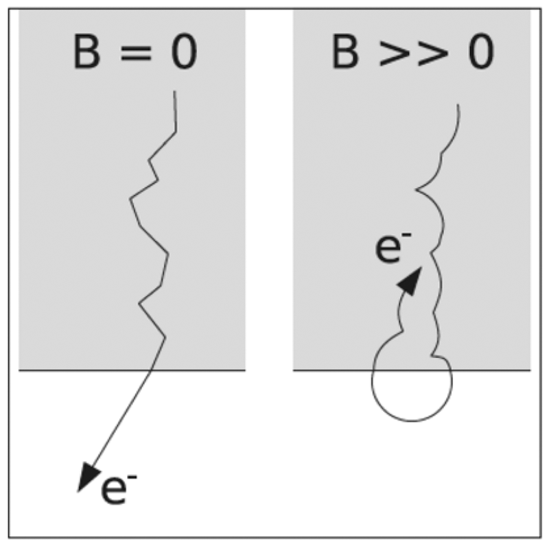
The anticipated workflow with the Elekta MR-Linac is as follows:
A patient who is considered for treatment with the MR-Linac will undergo imaging for treatment simulation and planning, either with CT or MRI. In the case of MR simulation, a synthetic CT might be constructed to enable heterogeneity corrections without requiring additional imaging with CT (Nesvacil et al., 2016). As is currently customary in radiation therapy, a radiation oncologist will contour the gross tumour volume and clinical target volume (CTV) (ICRU, 1999). A dosimetrist (with the assistance of software) will contour the planning target volume and organs at risk (OARs). A reference treatment plan will then be prepared and approved by the radiation oncologist. The planning system must be capable of representing the beam energy and geometry of the MR-Linac, as well as the effects of the magnetic field. When the patient returns for treatment, he/she will be positioned on the treatment table of the MR-Linac and a 3D volumetric MR image set will be obtained. The daily MR image set will be deformably registered with the reference treatment plan (Wang et al., 2005; Brock et al., 2006), and necessary modifications to the CTV will be made by the radiation oncologist. The reference treatment plan will then be adapted to the daily MR images and a new plan calculated. This new plan can potentially achieve a greater dose to the CTV if changes in the nearby OARs permit escalation of dose. The adapted treatment plan will require some sort of quality assurance (QA) process to assure its veracity. As the patient remains on the treatment table during the adaptation procedures, a measurement will not be practical. Instead, a redundant calculation will be carried out with an independent treatment planning computer. While the adapted treatment plan is being developed and the QA procedures are executed, there is the opportunity for functional imaging to evaluate potential progression of the patient’s tumour or, on subsequent treatment visits, biochemical or anatomical response to earlier treatments. When the adapted plan has been approved, treatment is delivered. During treatment, a fast imaging sequence will be executed to observe and potentially compensate for patient movement. The beam can be gated whenever the excursions of the CTV exceed predefined limits, or instructions can be sent to the multi-leaf collimator to track the motion of the target.
An approach that mimics the CT-on-rails systems described earlier also offers the potential of combining a diagnostic-quality 1.5 T MRI scanner with a treatment unit. One effort has been to install an MRI scanner in a room adjacent to a linac, a high-dose-rate brachytherapy unit, or even multiple treatment devices. The idea behind this arrangement was that the MRI scanner could be used as a simulator in one of the rooms, could be moved into a linac room to provide external-beam IGRT, or could be moved into a brachytherapy suite for image-guided brachytherapy, thus making effective use of the MRI scanner while also maximising utilisation of the treatment units (Bostel et al., 2014; Jaffray et al., 2014). Such an arrangement raises questions about the effect of the magnetic field on adjacent treatment devices, an issue that can have consequences important to the department’s QA programme (Kok et al., 2009).
Chen et al. (2018) reported their experience in head and neck cancer using a low-field strength (0.3 T) MR system combined with a 60Co treatment device (MRIdian, ViewRay Inc, Oakwood Village, OH, USA) (Mutic and Dempsey, 2014). Due to the newness of this modality, their study was necessarily small and examined patient-reported outcomes in 17 patients. The incidence of grade 3+ acute toxicity was 44%, although 70% of patients reported their health-related quality of life as ‘very good’ or ‘outstanding’ at 1 year after treatment. The use of a low-field strength magnet almost eliminated any influence of the magnetic field on the dose distribution.
Similar efforts to combine higher-field magnets with higher-energy treatment units have been reported recently. A team in Canada has built a 0.5 T magnet combined with a 6 MV linac (Fallone, 2014), while a group in Australia has proposed an MRI-guided cobalt tomotherapy system (Kron et al., 2006), and another group has constructed a system using a 1 T magnet and a 6 MV linac (Keall et al., 2014). Each of the linac-driven devices proposes to allow orienting the radiation beam perpendicular or parallel to the magnetic field, in an effort to minimise the effects of the magnetic field on the dose distribution.
5.2. PET/biology emission-guided radiation therapy
In another novel development, Fan et al. (2012) proposed combining the imaging features of positron emission tomography (PET) with MV radiation delivery. The result is called ‘emission-guided radiation therapy’ (EGRT), and the goal is to use the lines of response from positron emission events to guide beams of therapeutic radiation to the emission sites within a tumour.
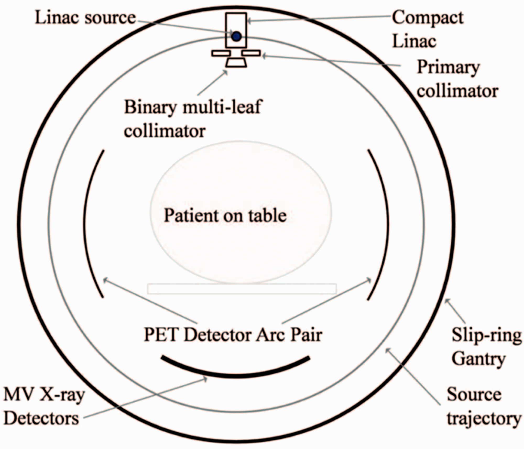
The preferential uptake of PET radionuclides, such as fluorodexoyglucose labelled with 18F, suggests that the annihilation radiation emanating from the tumour could be used to target the tumour volume with radiation therapy (see Fig. 7). Fan et al. (2012) have done just this, by constructing a linear accelerator on a rotating gantry with opposing banks of PET detectors mounted on the same gantry. As annihilation photons from the target volume are detected, the linac is gated on to deliver radiation to exactly the spot from which the annihilation radiation originated (see Fig. 8).
A comparison of a computed tomography (CT) scan (left) and a positron emission tomography (PET)/CT scan (right) of a patient with lung cancer. The comparison demonstrates the ability of PET to highlight cancer cells. Reproduced courtesy of RefleXion Medical. A cross-sectional diagram of a system for emission-guided radiation therapy. Positron emission tomography (PET) detectors are symmetrically opposed, and a linac with a electronic portal imaging detector mounted in opposition is oriented perpendicularly. The entire system rotates while the patient table moves in the longitudinal direction, so that treatment is delivered helically. Source: Fan et al. (2012), reproduced with permission.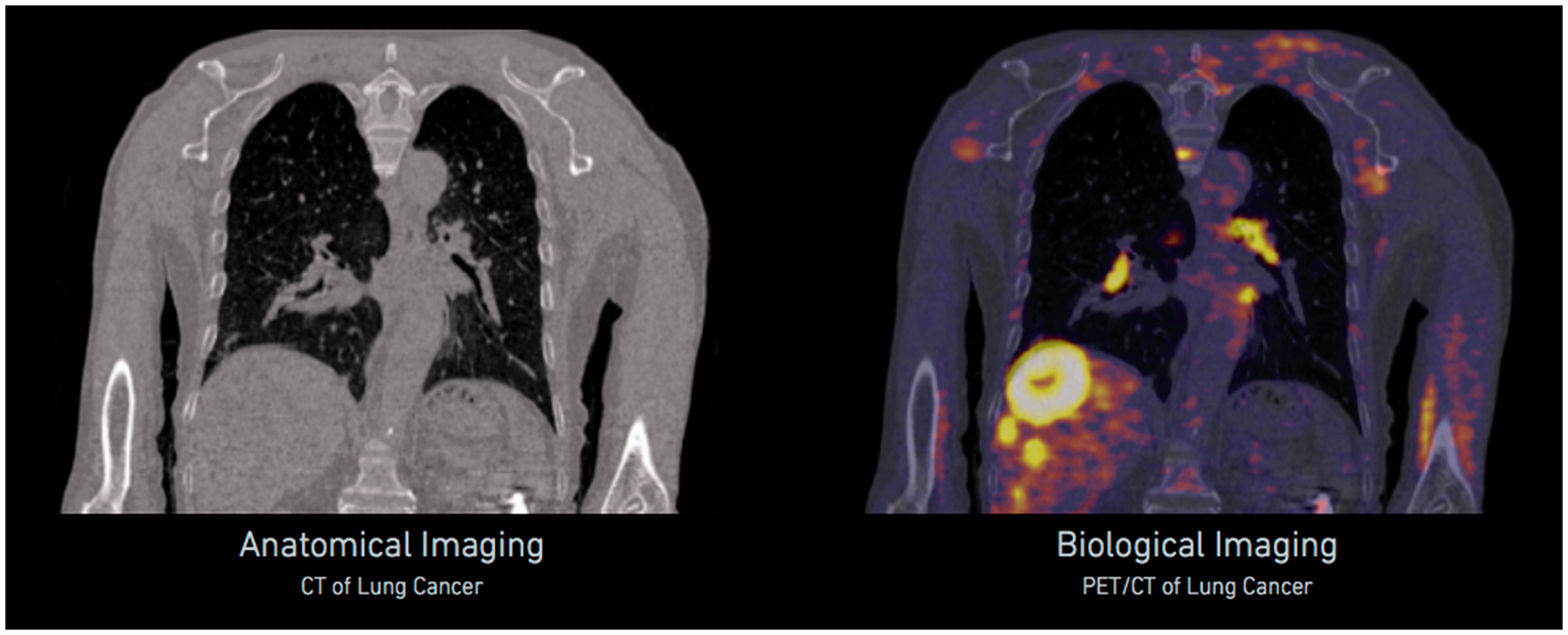
Subsequently, novel imaging agents have been developed to facilitate imaging and treatment guidance with both MRI and PET. One example has been the use of gold nanoparticles (GNPs), which have been assessed for their ability to increase local dose deposition in radiation therapy. Hainfeld et al. (2004, 2008) showed dose enhancement in a 250 kV x-ray beam. Mignot et al. (2013) developed a gadolinium-based GNP known as AGuIX, which functions as a non-toxic MRI contrast agent while being sufficiently small to allow renal clearance. Detappe et al. (2015) evaluated these MR-visible GNPs in the treatment of pancreatic cancer. A significant recent development was to label the gadolinium-containing AGuIX GNPs with the positron emitter 68Ga, creating an agent that is visible under both MRI and PET, and potentially usable for PET-/MRI-guided radiation therapy (Bouziotis et al., 2017).
5.3. Image-guided brachytherapy
The use of MRI to guide the delivery of brachytherapy has been reported by a number of authors, and guidelines developed by the European Society for Radiotherapy and Oncology have been published (Haie-Meder et al., 2005). MRI is particularly useful to demonstrate tumour involvement in the uterine cervix, rectum, and prostate, and its expanded use has required the development of MR-compatible applicators for high-dose-rate brachytherapy. These are now widely available, and the use of MRI for guidance has encouraged the brachytherapy community to adopt volume-based prescriptions and move away from historical point-based techniques (Erickson, 2015). Additionally, contemporary deformable image registration algorithms have been demonstrated to be valuable in identifying target volumes for gynaecological radiation therapy (Chapman et al., 2016).
6. Conclusions
Image guidance in radiation therapy has undergone major advances in recent years. The introduction of OBI and CBCT have brought kV imaging of cancer patients while in the treatment position within reach of essentially all modern radiation therapy departments. Clinical benefits of regular image guidance have been demonstrated, as have adaptations in treatment plans, as a result of patient changes observed through imaging. The field is on the verge of several practice-changing advances in IGRT, with the introduction of MR and PET guidance systems, and the development of hybrid MR or PET imaging systems and treatment devices. These advances have the potential to disrupt conventional radiation therapy prescriptions, and move the field towards daily adjustments in treatment dose and dose distribution, driven by changes in the patient’s anatomy and tumour response. Growing concern regarding x-ray exposures of normal body tissues associated with IGRT may require dose tracking similar to that used in diagnostic imaging.