
Abstract

Editorial
This issue completes the first volume of the Annals of the ICRP published with SAGE. The four issues of this volume (which represent 1 year of publications, at least notionally) are a reasonable cross-section of the types of reports published by ICRP. Publication 124 (ICRP, 2014a) was on protection of the environment, Publications 125 (ICRP, 2014b) and 126 (ICRP, 2014c) examined the application of the system of radiological protection to specific circumstances, specifically security screening and protection against radon, and the current publication addresses radiological protection in medicine.
An even better appreciation for the number and types of reports published by ICRP can be gained by looking at what has been published since the 2007 Recommendations (ICRP, 2007).
Twenty-six publications (many being multiple issues) have been produced in the past 7 years. Three of these were produced jointly with our sister organisation, the International Commission on Radiological Units and Measurements (ICRU), and one was published by ICRU (2010).
More than one-quarter of these publications, seven of the 26, are in the medical area. This is not surprising given that medicine is where ICRP, originally named the International X-ray and Radium Protection Committee (IXRPC), began in 1928. Radiological protection in medicine continues to be a major focus today.
Six publications are related to calculation of dose. This is perhaps more than average for a collection of 26 ICRP publications. This is a result of the enormous effort that has been made, and remains ongoing, to produce a full new set of dose coefficients for radiological protection purposes. Many more publications in this area will follow in the coming years.
Three publications address radiological protection of the environment, an area that ICRP began to tackle in earnest almost a decade ago with the creation of ICRP Committee 5, although results of earlier efforts are evident [e.g. in Publication 91 (ICRP, 2003)].
Seven publications support and clarify how the principles of the system of radiological protection apply beyond medicine and the environment, dealing with protection of people in such diverse circumstances as radon in homes, astronauts in space, and post-accident recovery.
Two extensive reports have been reviews of current areas of science, and implications of this new knowledge for the system of radiological protection. Scientific understanding is one of the three pillars that form the foundation of the system, the others being ethical values and experience. The system of radiological protection must continue to evolve to remain solidly based on all three of these pillars.
The one remaining publication since 2007 is the proceedings (ICRP, 2012) of ICRP’s First International Symposium. This took place near Washington, DC, USA in October 2011. Our Second International Symposium on the System of Radiological Protection was held 2 years later in Abu Dhabi, United Arab Emirates. The proceedings for this symposium are due to be published shortly, and pre-press articles are already available electronically at the time of writing this editorial. ICRP’s Third International Symposium on the System of Radiological Protection will be held in October 2015 in Seoul, Korea, and plans are already underway for future symposia. These biennial ICRP events, attracting many hundreds of radiological protection professionals from around the world, have become a cornerstone in our efforts to be a more open and transparent organisation. Radiological protection in medicine has featured highly in each of the symposia to date, and will continue to do so.
This current publication continues ICRP's nearly 90-year focus on radiological protection in medicine. Since that time, the most basic principle in all circumstances has remained the same: providing protection from the negative effects of exposure to radiation while not unduly limiting the related benefits. However, even at this fundamental level, there are some important differences between the recommendations of 1928 and today. The first recommendations of IXRPC (IXRPC, 1928) related to safety of medical professionals and researchers through ‘the provision of adequate protection and suitable working conditions’. Interestingly, this included providing fresh air and sunshine, and ‘not less than one month’s holiday a year’ for ‘whole-time X-ray and radium workers’. However, there were also more recognisable recommendations; for example, ‘An X-ray operator should on no account expose himself unnecessarily to a direct beam of X-rays’ and ‘should place himself as remote as practicable from the X-ray tube’. Perhaps it is a bit of a stretch, but these and other considerations in the 1928 Recommendations are not too far away from the ideas of justification and optimisation used today.
Today, ICRP recommendations extend protection beyond those who work with radiation, to patients and members of the public. Chapter 6 of the current publication deals with protection of workers and the public, considering, for example, management of activated devices, air in the treatment room and being discharged, management of solid waste, and release of patients. Chapter 7 focuses on protection of patients through prevention of accidental exposures from ion beam therapy. Covering protection of workers, patients, and the public is not a special feature of the current publication. In recent years, ICRP has made an effort to include all of these aspects in publications on radiological protection in medicine.
Of course, protection is not enough. Developments in ion beam radiotherapy have been motivated by the benefits provided by improved treatment of tumours. Although these benefits are not the focus of this publication, these recommendations would not be necessary without the success of ion beam therapy as described in the introduction to this report. While the business of ICRP is protection against negative effects of radiation, developments such as ion beam radiotherapy are very much welcomed as they improve the overall human condition. ICRP will continue to accompany developments of the use of beneficial radiation in medicine and in other areas, to help ensure that these wonderful new technologies and techniques are used safely.
CHRISTOPHER H. CLEMENT
ICRP SCIENTIFIC SECRETARY EDITOR-IN-CHIEF
References
Radiological Protection in Ion Beam Radiotherapy ICRP Publication 127
Approved by the Commission in October 2014
© 2014 ICRP. Published by SAGE.
Keywords: Radiotherapy; Ion beam; Proton; Carbon ion
Preface
Over the years, the International Commission on Radiological Protection (ICRP) has issued many reports providing advice on radiological protection and safety in medicine. Publication 105 is a general overview of this area (ICRP, 2007d). These reports summarise the general principles of radiological protection, and provide advice on the application of these principles to the various uses of ionising radiation in medicine.
Most of these reports are of a general nature, and the Commission wishes to address some specific situations where difficulties have been observed. Reports on such problem areas should be written in a style that is accessible to those who may be directly concerned in their daily work, and every effort should be taken to ensure wide circulation of such reports.
Rapid advances in radiotherapy require practical guidance for radiological protection of patients and medical staff. Publication 86 (ICRP, 2000) dealt with the prevention of accidental exposure of radiotherapy patients, and provided the lessons learned from real case histories of major accidental exposures, and recommendations to prevent such accidental exposure of patients. Publication 112 (ICRP, 2009) followed the same theme with particular emphasis on new technologies in external radiotherapy.
Ion beam radiotherapy is a recently introduced technique that could potentially offer an improved dose conformation to the target volume with better sparing of the surrounding normal tissue. As ion beam radiotherapy requires a more complex treatment system than conventional radiotherapy, appropriate training of staff and suitable quality assurance programmes are recommended to avoid possible accidental exposure of patients, and to keep radiation exposure of staff to a minimum level. The Commission launched a Task Group on Radiological Protection in Ion Beam Radiotherapy in 2012.


The membership of Committee 3 during the period of preparation of this report was:
MAIN POINTS
GLOSSARY
Absorbed dose, D
The fundamental dose quantity given by:
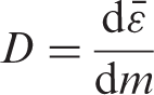
where d
Activation Physical phenomenon in which radioactivity is induced in materials irradiated with radiation such as high-energy photons, neutrons, and ion beams.
Bragg peak The Bragg peak is a pronounced peak on the Bragg curve that plots the energy loss of ion beams during their passage through matter. For protons and other ions, the peak occurs near the end of their range. In radiation therapy with ions, the term ‘Bragg peak’ is used for the peak in the curve of absorbed dose against depth in the irradiated phantom or patient. Although this is not strictly correct, this usage is applied in this report (see also ‘Spread-out Bragg peak’).
Broad beam A beam of radiant energy covering the irradiation field entirely in an approximately conical or cylindrical portion of space of relatively large diameter.
Broad beam (algorithm) One of the dose calculation techniques for radiotherapy treatment planning. It assumes that any beam incidenting the patient travels straight on the incident axis through the patient with no lateral blurring. The dose at any point of interest is given as a function of the corresponding thickness to the point on the beam axis.
Broad beam (irradiation technique) Incident beam from an accelerator is broadened laterally to cover the target uniformly. The ‘broad beam’ is then shaped using a collimator to match the irradiation field to the cross-section of the target.
Cone beam computed tomography (CBCT) A form of x-ray computed tomography in which the x rays, in the form of a divergent cone or pyramid, illuminate a two-dimensional detector array for image capture. It can also be referred to as ‘digital volume tomography’.
Deterministic effect Injury in populations of cells, characterised by a threshold dose and an increase in the severity of the reaction as the dose is increased. It is also termed ‘tissue reaction’. In some cases, deterministic effects are modifiable by post-irradiation procedures including biological response modifiers.
Detriment The total harm to health experienced by an exposed group and its descendants as a result of the group’s exposure to a radiation source. Detriment is a multidimensional concept. Its principal components are the stochastic quantities: probability of attributable fatal cancer, weighted probability of attributable non-fatal cancer, weighted probability of severe heritable effects, and length of life lost if the harm occurs.
Diagnostic reference level Used in medical imaging with ionising radiation to indicate whether, in routine conditions, the patient dose or administered activity (amount of radioactive material) from a specified procedure is unusually high or low for that procedure.
Dose equivalent, H The product of D and Q at a point in tissue, where D is the absorbed dose and Q is the quality factor for the specific radiation at this point, thus:

The unit of dose equivalent is joule per kilogramme (J kg−1), and its special name is sievert (Sv).
Effective dose, E
The tissue-weighted sum of the equivalent doses in all specified tissues and organs of the body, given by the expression:
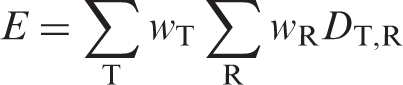
or:
where HT or wR DT,R is the equivalent dose in a tissue or organ, T, and wT is the tissue weighting factor. The unit for effective dose is the same as for absorbed dose (J kg−1), and its special name is sievert (Sv).
Equivalent dose, HT
The dose in a tissue or organ T given by:
where DT,R is the mean absorbed dose from radiation R in a tissue or organ T, and wR is the radiation weighting factor. As wR is dimensionless, the unit for equivalent dose is the same as for absorbed dose (J kg−1), and its special name is sievert (Sv).
Fluence, Φ
The quotient of dN by da, where dN is the number of particles incident on a sphere of cross-sectional area da, thus:
Intensity-modulated radiotherapy (IMRT) Advanced mode of high-precision radiotherapy that uses computer-controlled linear accelerators to deliver precise radiation doses to malignant tumour or specific areas within the tumour. IMRT can make appropriate three-dimensional dose distribution by modulating the intensity of the radiation beams from multiple directions.
Lineal energy
The lineal energy, y, is the quotient of εs by
The unit of y is given in J m−1 or keV µm−1.
Linear energy transfer (LET) The average linear rate of energy loss of charged particle radiation in a medium (i.e. the radiation energy lost per unit length of path through a material). That is, the quotient of dE by dl where dE is the mean energy lost by a charged particle owing to collisions with electrons in traversing a distance dl in matter:
The unit of L is J m−1 or keV µm−1.
MeV n−1 Kinetic energy of a particle expressed by a unit of mega-electron volt per nucleon (MeV n−1). It reflects the square of the speed v of the particle. Particles sharing the same MeV n−1 value have the same β = v/c (where c is light speed).
Millibarn (mb) Barn is a unit of area, originally used in nuclear physics for cross-sectional area of nuclei and defined as 10−28 m2. 1 mb is equal to 10−31 m2.
Organ at risk (OAR) An organ that may be damaged during exposure to radiation. OAR most frequently refers to healthy organs located in the radiation field during radiotherapy.
Oxygen enhancement ratio (OER) The ratio of the absorbed dose required to cause the same biological endpoint in hypoxic conditions as in normoxic conditions. Hypoxia often occurs in the middle of a rapidly growing tumour. The OER of x rays is approximately 3, while high-LET radiation tends to show smaller OERs down to 1, indicating that high-LET radiation is effective against hypoxic tumours.
Pencil beam A beam of radiant energy concentrated in an approximately conical or cylindrical portion of space of relatively small diameter.
Pencil beam (algorithm) One of the dose calculation techniques for radiotherapy treatment planning. It assumes that any beam incidenting the patient is actually a conglomeration of lots of ‘pencil beams’, and the dose at any point of interest is given as the superposition of all the pencil beams.
Pencil beam (in scanning irradiation technique) Dose is delivered by superposing ‘pencil beams’ from an accelerator on the target by controlling the beam path three-dimensionally.
Quality factor, Q(L)
The factor characterising the biological effectiveness of a radiation, based on the ionisation density along the tracks of ion beams in tissue. Q is defined as a function of the unrestricted linear energy transfer, L∞ (often denoted as L or LET), of ion beams in water:
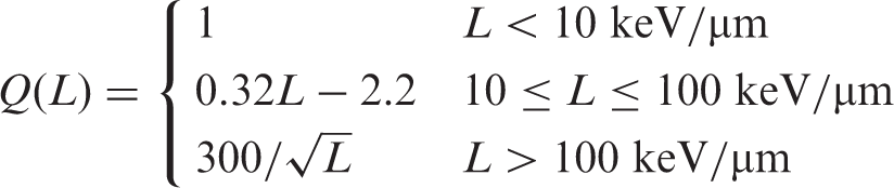
Q has been replaced by the radiation weighting factor in the definition of equivalent dose, but is still used in calculating the operational dose equivalent quantities for monitoring purposes.
Radiation detriment A concept used to quantify the harmful health effects of radiation exposure in different parts of the body. It is defined by the Commission as a function of several factors, including incidence of radiation-related cancer or heritable effects, lethality of these conditions, quality of life, and years of life lost due to these conditions.
Radiation-induced second cancer Ionising radiation has paradoxical aspects in both beneficial effects of curing cancer and the risk of inducing cancer. Induction of cancer by low to high doses of radiation has been demonstrated by the significant increase in the incidence of cancers among workers handling radioactive substances and among atomic bomb survivors, as well as among survivors after radiotherapy.
Radiation weighting factor, wR A dimensionless factor by which the organ or tissue absorbed dose is weighted to reflect the higher biological effectiveness of high-LET radiation compared with low-LET radiation. It is used to derive the equivalent dose from the absorbed dose averaged over a tissue or organ.
Relative biological effectiveness (RBE) The ratio of a dose of a low-LET reference radiation to a dose of the radiation considered that has an identical biological effect. RBE values vary with the dose, dose rate, and biological endpoint considered.
Secondary radiation Radiation produced by interaction between the primary beam and the matter. In the radiotherapy treatment room, all radiation except for the primary beam is secondary radiation, which is produced by scattering of objects or leakage through the protective shield.
Spread-out Bragg peak (SOBP) The extended isoeffect region in depth formed by the optimal stacking of multiple depth dose curves of pristine Bragg peaks of different energies.
Stochastic effect The induction of malignant disease or heritable effects for which the probability of an effect occurring, but not its severity, is regarded, for the purpose of radiological protection, to be increasing with dose without a threshold.
Time-resolved computed tomography (4DCT) X-ray computed tomography apparatus capable of rapidly acquiring serial three-dimensional volumetric images as a function of time. The image is often associated with breathing or heartbeat phase.
Tissue reaction See ‘Deterministic effect’.
Tissue weighting factor, wT
The factor by which the equivalent dose in a tissue or organ T is weighted to represent the relative contribution of that tissue or organ to the total health detriment resulting from uniform irradiation of the body (ICRP, 2007b). It is weighted such that:
Voxel phantom Computational anthropomorphic phantom based on medical tomographic images where the anatomy is described by small three-dimensional volume elements (voxels) specifying the density and the atomic composition of the various organs and tissues of the human body.
1. INTRODUCTION
Considerable progress has been made in the treatment of patients with radiation in terms of increased applicability and improved therapeutic outcomes. Most notably, high-precision photon beam radiotherapy, such as intensity-modulated radiotherapy (IMRT) and stereotactic radiotherapy, are used effectively in clinical practice. The goal of external radiotherapy is precise dose localisation in the treatment volume of the target, with minimal damage to the surrounding normal tissue. The success of treatment largely depends on the performance and capacity of accelerators and the treatment planning system (TPS), in addition to accurate delineation of the targeted tumour volume and patient positioning by the radiation oncologist. This became particularly evident in the 1950s, when it was recognised that high-energy photons contributed significantly to improvement of the treatment outcome. The beginning of modern radiotherapy takes its origins in the 1950s when cobalt therapy units and high-energy accelerators were developed and applied to clinical use. Cancer therapy with ion beams has a history of more than 50 years (Tobias et al., 1956). Ion beam radiotherapy is characterised by production of the maximum ionisation density at depth in tissue, referred to as the ‘Bragg peak’, and therefore offers an improved dose conformation to the treatment volume with better sparing of the surrounding normal tissue compared with photon beams. Furthermore, protons and heavier ion beams allow a reduction of the total energy deposited in the patient compared with photon techniques. In many cases, this allows dose escalation in the target or a significant reduction in dose to healthy tissue. The latter is of particular importance if the treatment volume is close to critical structures. In addition, ion beams, such as protons and carbon ions, exhibit a strong increase in linear energy transfer Ion beam radiotherapy with protons is becoming popular in some countries, and carbon ion radiotherapy has also been introduced in medical care. Approximately 10 years ago, there were nearly 20 ion beam radiotherapy facilities in the world.
a
At the time of writing, this number has doubled and many new facilities are being built or planned. Potential demand is anticipated to exceed the projected increased number of facilities. High-energy radiation is necessary for ion beam radiotherapy. The treatment facility generally requires a large-scale accelerator installed in the building with appropriate shielding. There are specific issues in radiological protection to operate such a treatment facility. A result of the worldwide development and spread of high-precision radiotherapy has been the increased opportunity to treat benign diseases and malignant cancers in young patients. The therapeutic outcome has also been improved for locally advanced cancers that were not curable with conventional methods. Many of these patients now survive for longer periods, and thus, more attention should be paid to any late-occurring radiation effects. In the past, radiation oncologists focused mainly on curing cancers with little consideration of second cancers or radiotherapy-related cardiovascular disease. Recently, the situation has changed; while high-precision photon radiotherapy methods are superior in terms of the dose distribution they deliver to a tumour, a large volume of the surrounding normal tissue may be exposed to low and medium levels of dose (NCRP, 2011). Ion beam radiotherapy with protons or carbon ions largely contributes to localised dose to the tumour, and the additional dose received by the surrounding normal tissue is reduced. However, the possible risk of high-LET radiation in the surrounding normal tissue may be of more general concern, despite the fact that the absolute dose level is reduced. This report reviews the present status and problems associated with the use of ion beam radiotherapy from the viewpoint of radiological protection and safety, and provides practical guidance for the effective and safe use of ion beams for medical treatment of benign and malignant disease.
2. OUTLINE OF ION BEAM RADIOTHERAPY
2.1. Clinical target of ion beam radiotherapy
The introduction of new technologies in radiotherapy aims to improve treatment outcome by means of a dose distribution that conforms more strictly to the tumour volume and treatment volume (ICRP, 2009). Ion beams are considered to have the optimum properties for dose localisation. The selection of patients suitable for ion beam radiotherapy is the first step in the treatment. Benefits of ion beam therapy can be achieved in patients with solid cancer with defined borders. This non-invasive treatment does not require surgery to remove the cancer, making it ideal for inoperable tumours. Proton beam radiotherapy may offer clinical advantages compared with conventional photon radiotherapy for many cancers, mainly as a result of a more favourable distribution of the radiation dose (Lundkvist et al., 2005). Ion beams that are heavier than protons have the additional advantage of enhanced biological effects; these increase with depth, reaching a maximum at the end of the beam’s range. These unique properties have led to the use of heavy ion beams, such as helium, carbon, and neon ions, for cancer radiotherapy. The carbon ions enable the treatment of various tumours that are resistant to conventional photon radiotherapy or chemotherapy (Chauvel, 1995). The clinical benefits of carbon ion radiotherapy have been demonstrated in non-squamous cell tumour types, including sarcoma, malignant melanoma, adenocarcinoma, adenoid cystic carcinoma, and chordoma (Tsujii and Kamada, 2012). Some studies have suggested that new technology has not yet resulted in a substantial improvement in the long-term outcome for most patients (Soarers et al., 2005), and there is a need for systematic evaluation of the benefits, considering the total cost of the method (Allen et al., 2012; Lievens and Pijls-Johannesma, 2013).
2.2. General treatment processes
2.2.1. Features of ion beams
Ion beams, as indicated above, are characterised by dose concentration at depth in tissue and enhanced biological effectiveness. The clinical advantage results from a steeply rising absorbed dose, or Bragg peak, and a rapid decrease in dose after the peak. Therefore, by targeting the lesion within the Bragg peak, a superior dose concentration is achieved. This superiority is similar for both proton and carbon ion beams. Relative biological effectiveness (RBE) values vary for different endpoints for most cells and tissues, but tend to increase in parallel with increments of LET up to a maximum value before declining. Proton beams in clinical use are low-LET radiations, hence the RBE values are very close to those of high-energy x rays. The International Commission on Radiation Units and Measurements (ICRU) has recommended 1.1 as a generic RBE for proton beams (ICRU, 2007). This is based on the available evidence indicating that the magnitude of RBE variation with treatment parameters is relatively small compared with possible realistic RBEs. There is some concern about the use of a generic RBE value due to the limited range of data, particularly given the lack of human cell types, and future clarification is needed. For carbon ions, LET increases with depth in tissue, reaching a maximum at the end of a particle’s range. Carbon ions have higher RBE values than protons, but variations with depth in tissue and energy are not well defined. The available data indicate that the oxygen enhancement ratio (OER, the ratio of the absorbed dose required to cause the same biological endpoint in hypoxic conditions as in normoxic conditions) is reduced using high-LET radiation, and that high-LET radiation has less influence on the variation in radiosensitivity with respect to a phase in the cell division cycle. In order to treat cancers with ion beams, it is essential to have the knowledge and technology to use the characteristic features of the beams.
2.2.2. Imaging
Imaging technology plays a crucial role for precise localisation of the target volume in radiotherapy. In the case of ion beam radiotherapy, state-of-the-art diagnostic imaging with x-ray computed tomography (CT), magnetic resonance imaging, and positron emission tomography (PET) is indispensable in the entire procedure of treatment planning. For example, in treatment planning, CT gives patient density information to calculate dose distribution and design the shape of the spread-out Bragg peak (SOBP) to conform to the target volume. Recently, the PET-CT system has been developed, and this provides valuable diagnostic information for treatment planning. It is common to use x-ray exposures for patient positioning in ion beam radiotherapy.
2.2.3. High-precision beam delivery system
In order to appreciate the advantage of dose distribution, ion beams are spread to conform to the target by passive scattering, pencil beam scanning, and wobbling or uniform scanning. Thus, the high-precision beam delivery system covers the target with the designed spread beam with millimetre accuracy. In the past, the most commonly used method was passive beam scattering, including single and double scattering. For the treatment of a target volume moving with respiration, the respiratory-gated irradiation method has been used in passive scattering.
2.2.4. Procedures for ion beam radiotherapy
Procedures for ion beam radiotherapy are described below. These include patient immobilisation, planning CT, treatment planning, patient positioning, and beam delivery.
Patient immobilisation
Rotating gantries have become available for proton radiotherapy (Slater, 1995), while fixed horizontal or vertical beams are used in most carbon ion therapy facilities. In the case of fixed beam lines, different beam directions can only be achieved by a combination of patient’s positions, with or without rotating the patient. Normally, ion beam radiotherapy is fractionated over several weeks. It is crucial for radiotherapy to repeat the beam delivery with high precision over the period. Initially, it is important to examine diagnostic images to determine the treatment sites and available beam directions. Immobilisation must be sufficiently robust to maintain its integrity for the duration of treatment, and fully support a reproducible patient treatment position. In some cases, physiological factors are actively controlled (e.g. bladder filling in patients with prostate cancer). For immobilisation, care should be taken not only for the patient’s comfort but also for the possible influence on the beam delivery. Safety and cost should also be included in the consideration. In many facilities, vacuum bags, bite blocks, individual cradles, and thermoplastics are used.
Planning CT
Treatment planning for ion beam radiotherapy is performed using CT images, which must be taken under the same conditions as used for treatment. The patient must be immobilised on the treatment couch under the same breathing conditions as for treatment. This sometimes requires respiratory gating for both CT scanning and subsequent beam delivery. The planning CT images provide patient density information for dose calculation. The use of contrast agents is therefore normally avoided in planning CT scans.
Treatment planning
The clinical target volume and organs at risk (OARs) are first defined on the planning CT images. In practice, additional diagnostic images, such as contrast-enhanced or breath-hold CT, magnetic resonance images, and PET images, are often helpful for delineation of the target if they are taken under treatment conditions (Hosokawa et al., 1995). The planning target volume is then determined, which also considers physiological changes between planning CT and treatment, organ motion (ICRU, 1993b, 1999; Osaka et al., 1997), and setup errors. The ion beams are designed to deliver the prescribed dose uniformly to the planning target volume, and beam parameters are chosen or varied to obtain an optimum dose distribution for the prescription (ICRU, 2007).
Patient positioning
For high-precision ion beam radiotherapy, the patient position is aligned and verified with orthogonal x rays in comparison with digital radiographs reconstructed from planning CT images for the setup of each patient. The reference planning images can be substituted by the equivalent x-ray images, which are taken prior to the first treatment. Bony structures and fiducial markers, implanted near the site before the planning CT, are often used as reference points in patient positioning.
Beam delivery
After the patient is immobilised and positioned, the ion beams are delivered as planned for a period of seconds or minutes. During beam delivery, the patient and active devices are visually or electrically monitored for interlock in case of any emergency. The beam is stopped when the prescribed dose is administered, for which the dose monitor output has to be calibrated prior to treatment. Due to the complexity of ion beam delivery systems, dose monitor calibration may require specific control measurement on a beam-by-beam basis.
2.3. Introduction of the beam delivery system and irradiation method
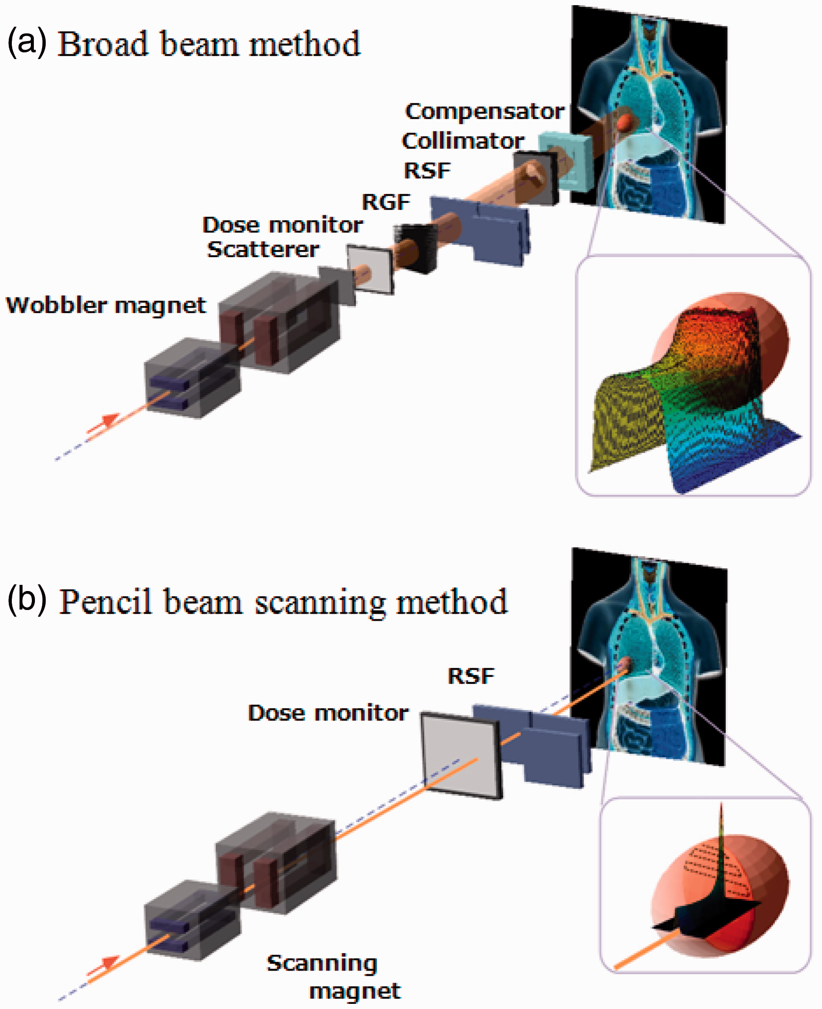
An ion beam delivery system generally consists of an accelerator system, a high-energy beam transport system, and an irradiation system. In most cases, a synchrotron, cyclotron, or synchro-cyclotron is used to accelerate particles. A high-energy ion beam is delivered through a beam transport system to an irradiation system. The narrow pristine beam extracted from the accelerator, which is called a ‘pencil beam’, is not ready for use in treatment except for the beam scanning method. The irradiation system broadens the pencil beam for the target volume. This method is called the ‘broad beam method’ and is classified as the ‘passive method’ (Fig. 2.1). A layer stacking method is a more advanced broad beam method that uses a multileaf collimator (MLC), resulting in higher relative dose being delivered to the target volume than the standard broad beam method (Kanai et al., 1983; Futami et al., 1999). In a scanning method, pencil beams are scanned over a target tumour, three-dimensionally, without expanding the pencil beam, unlike the conventional broad beam method (Fig. 2.2). The layer stacking and scanning methods are classified as ‘active methods’. Beam delivery system for carbon ion radiotherapy. (a) Concept of broad beam method. (b) Concept of pencil beam scanning method. RSF, range shift filter; RGF, ridge filter. Broad beam system with passive scattering for proton beam therapy. Reprinted from Goitein (2008).
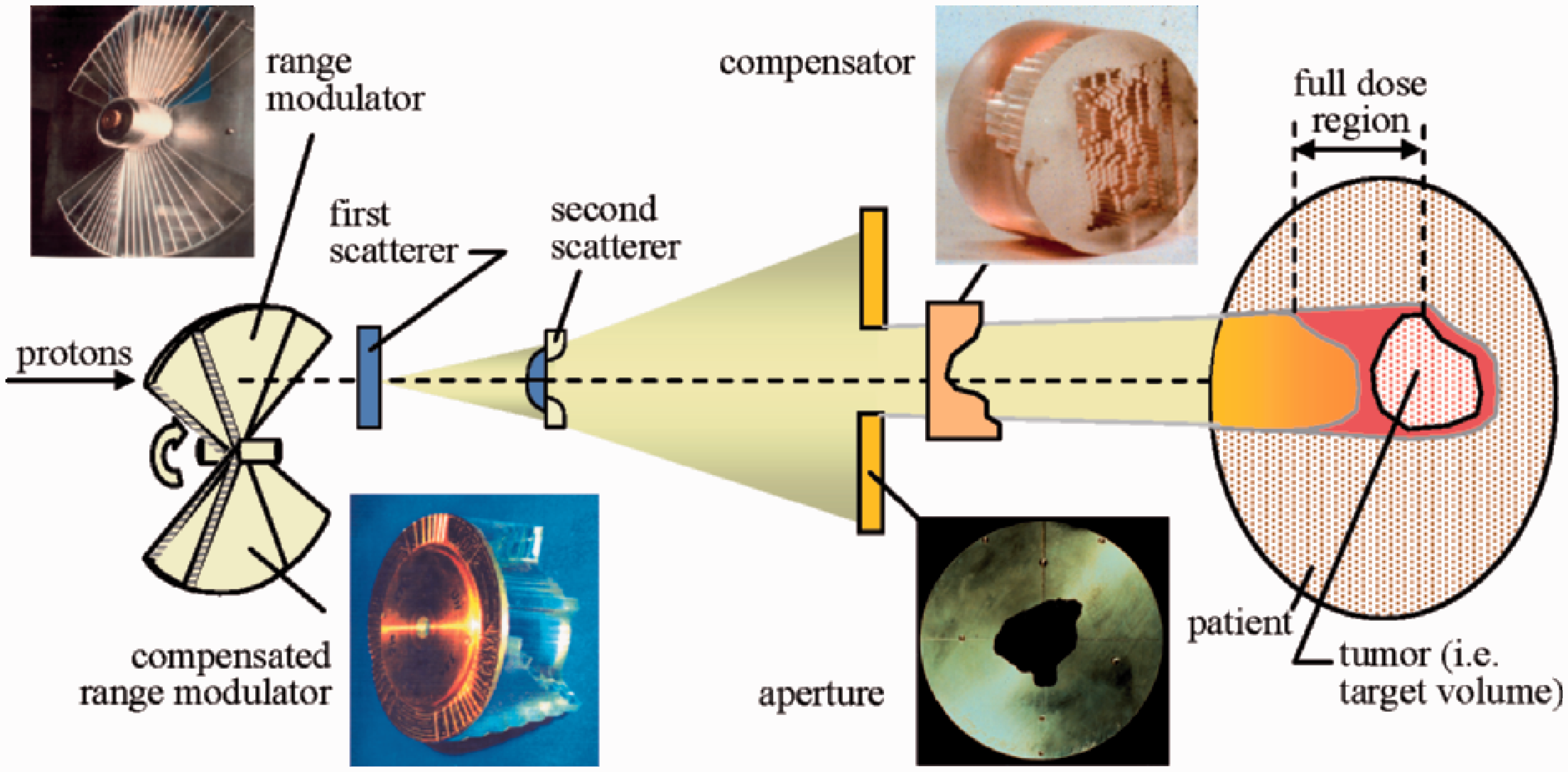
2.3.1. Broad beam method
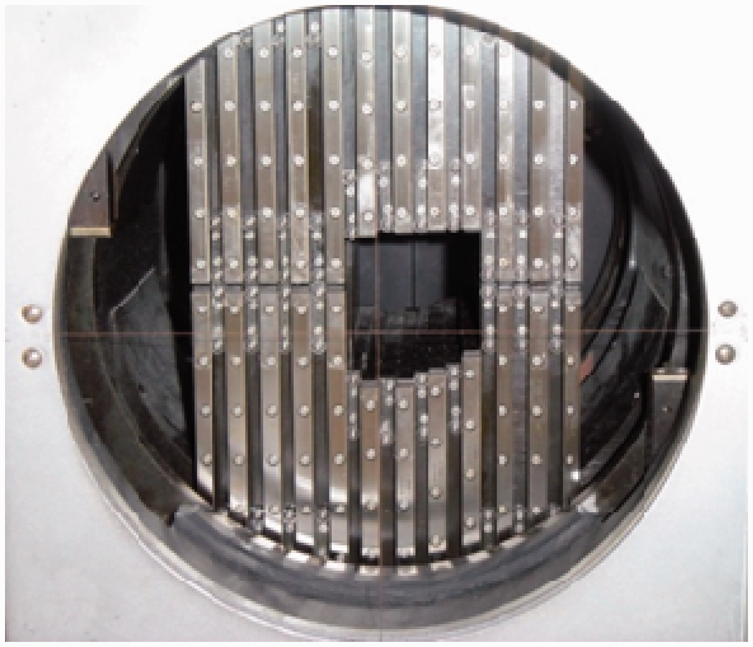
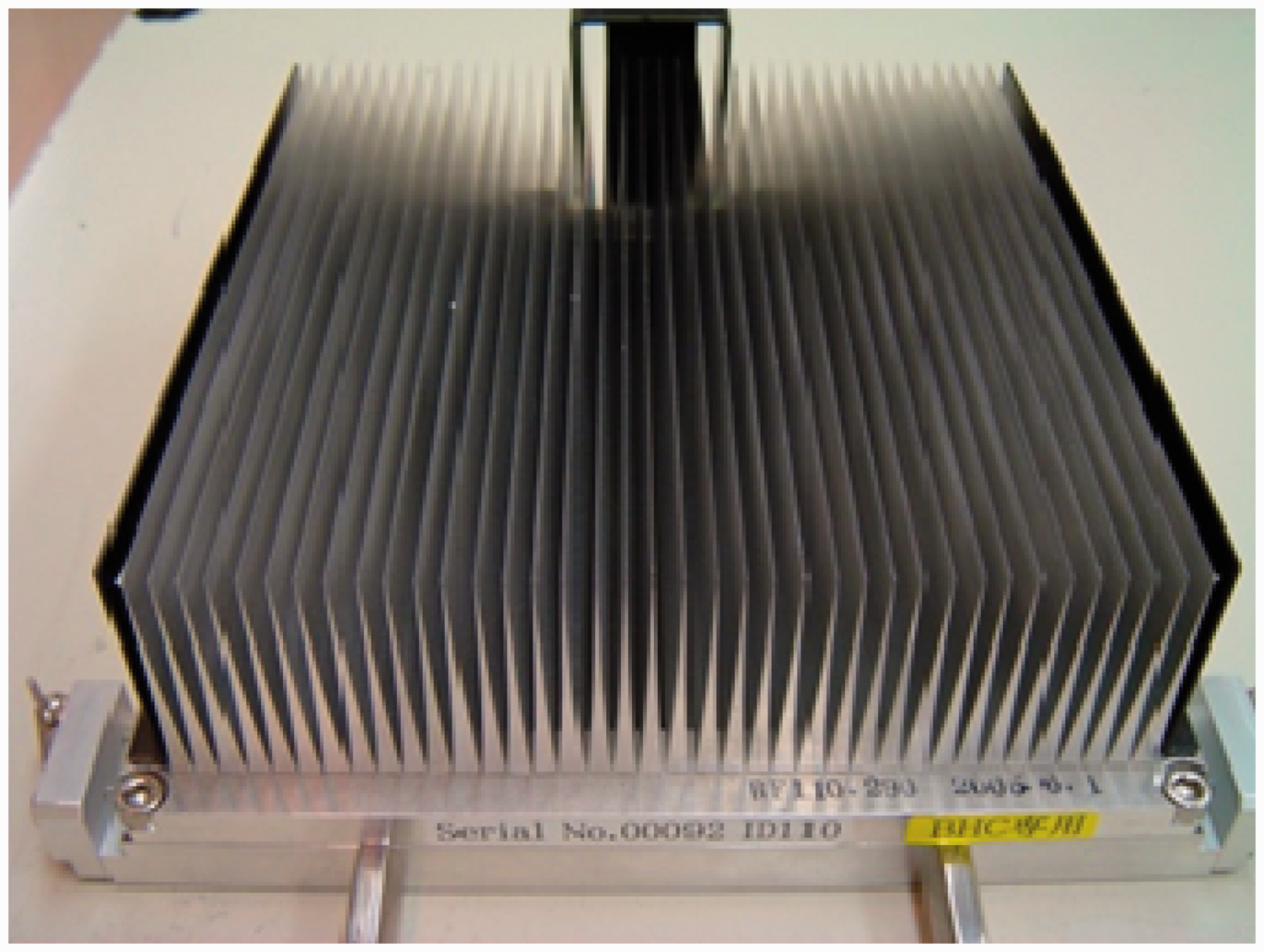
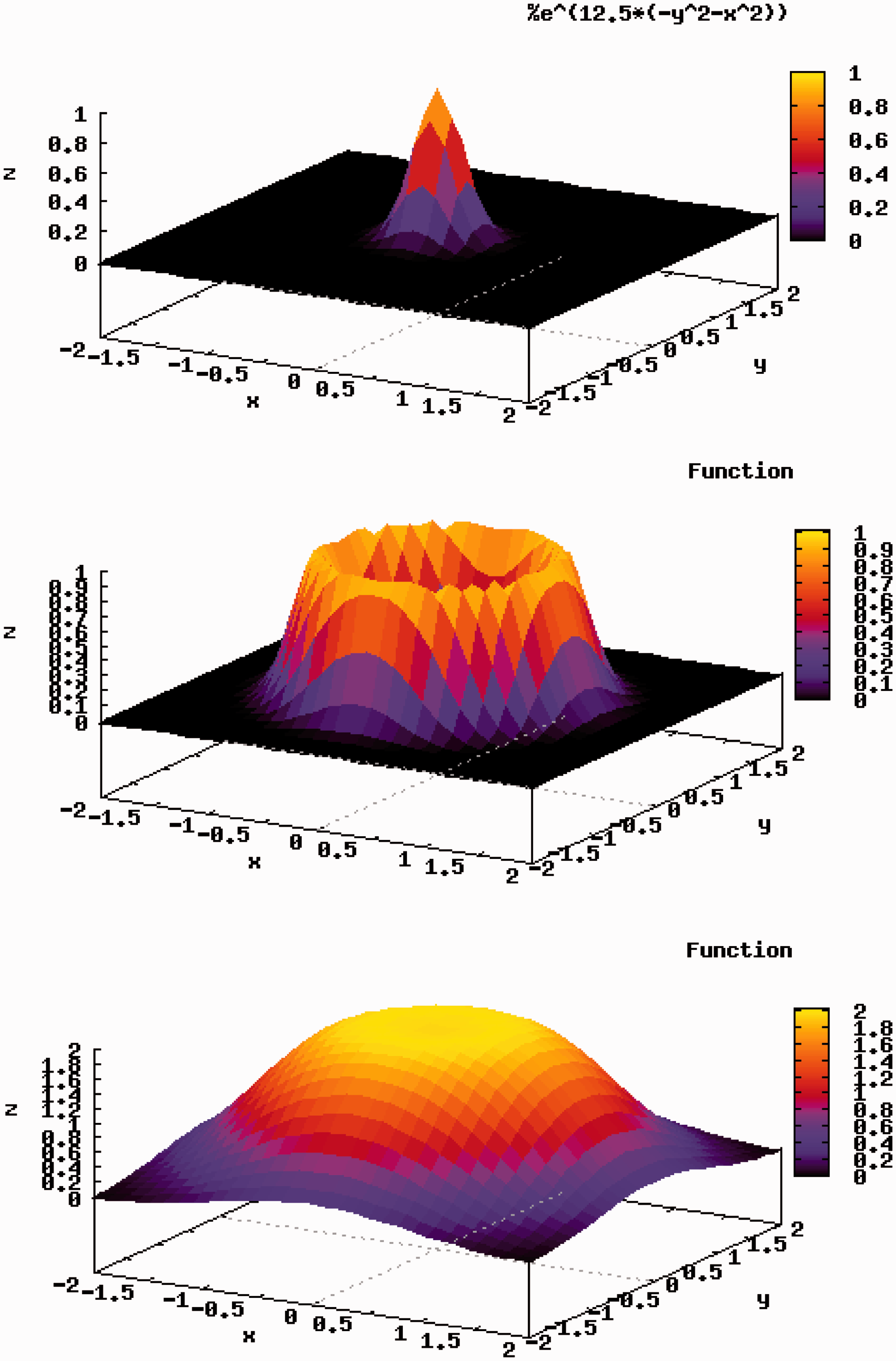
In the broad beam method, a narrow pencil beam, extracted from an accelerator, is broadened uniformly in the lateral and depth directions, and part of the expanded uniform beam is clipped to conform to the high-dose region induced by the beam to the target tumour volume in a patient’s body. The main methods used to widen the pencil beam uniformly in the lateral direction are double scattering and wobbler scattering. Single-scattering methods can be applied for small field sizes such as in radiosurgery. The double-scattering method (Fig. 2.1) makes a uniform irradiation field using two scatterers with different structures (Grusell et al., 1994; Gottschalk, 2008). The first scatterer, installed upstream in the irradiation system, is made of a uniform, heavy material (lead is commonly used), and the pencil beam is broadened by multiple Coulomb scattering. The distribution of the beam takes on a Gaussian-like shape with small tails. The second scatterer, placed downstream from the first scatterer, is made of two materials: a high Z component of decreasing thickness as a function of distance to the beam centre, and a low Z component of increasing thickness with distance to the beam centre. The wobbler-scattering method (Fig. 2.3) generates a uniform irradiation field using a combination of a wobbler-magnet system and a scattering system (Torikoshi et al., 2007). The wobbler-magnet system is a pair of bending magnets which are installed so that the direction of their magnetic fields is mutually orthogonal. By applying alternating currents to the two magnets, which are out of phase with each other by 90°, the pencil beam delivered from the accelerator is rotated in a circular pattern. The radius of the circle can be changed by varying the effective current supplied to the wobbler-magnet system. The annular beam is broadened by the scattering system placed downstream from the wobbler-magnet system. Uniform broadening of a beam, in the depth direction, corresponds to producing an SOBP. The SOBP is formed by superimposing many different pristine Bragg peaks. In other words, the SOBP is the response to energy modulation of a mono-energetic beam. There are two main ways of modulating beam energy and superimposing Bragg peaks: one uses a ridge filter device (Larsson, 1961; Kostjuchenko et al., 2001), and the other uses a rotating range modulator (Koehler et al., 1975). The ridge filter device is composed of many uniform bar-ridges, manufactured with highly precise processing technology, that are set parallel to each other on one plane as shown in Fig. 2.4. Ridge filter devices, corresponding to different SOBP widths, are often prepared for both high- and low-energy beams. As the cross-sectional shape of the bar-ridge determines the thickness of the beam, appropriate design of the bar-ridge allows delivery of a homogeneous weighted dose to the target region. A rotating range modulator is a wheel with a cyclic part of different water-equivalent thickness for different central angle regions. As a beam passes through the cyclic part, its energy is modulated by the thickness in the region where the beam passes. The depth-dose distribution formed using the rotating range modulator has a time structure corresponding to the rotation frequency of the modulator. After the broadening of a beam in the lateral and depth directions, the beam is shaped to the target tumour, projected in the beam’s eye view. A customised patient collimator, an MLC, or a combination is used for two-dimensional shaping of a uniform beam. A customised patient collimator is a block that has a tumour projection-shaped aperture. The block is thicker than the maximum range of the beam and often made of brass, which is easy to cut with a wire-electrical discharge machine or a milling machine. Although a customised patient collimator needs to be manufactured for each irradiation direction, it reduces blurring of the lateral dose falloff because the patient collimator can be placed near the body surface of the patient. An MLC has many pairs of thin leaves (Fig. 2.5). These leaves are shifted to suitable positions to make the aperture fit the tumour projected shape. Use of an MLC device has the advantage of increased speed and reduced costs for treatment preparation because no individual patient collimators need to be manufactured. On the other hand, due to mechanical limitations, MLCs often cannot be positioned as close to the patient’s surface as block collimators. The larger gap between the end of the collimator and the patient surface spoils the sharp lateral dose falloff to some extent. Therefore, MLCs are not often used when precise field shaping is required. A range shifter device is applied for the sake of adjusting the residual range in a patient’s body. A range shifter device is composed of several energy absorbers with different thicknesses, and the total thickness of the system can be changed by selecting suitable absorbers. The beam range can be adjusted uniformly by using a range shifter device. Range shifter devices are not commonly used in the treatment head (except for fine tuning), as synchrotrons can deliver the desired energy and cyclotrons typically use energy degraders at the cyclotron exit to send the desired energy into the treatment room. A patient compensator is a block that has an engraved depression in the shape of the distal surface of the target volume. The block is often made of high-density polyethylene which is easy to engrave and has a low atomic number to reduce scattering of the beam. Patient compensators, like patient collimators, also need to be manufactured for each irradiation direction. Regarding patient exposure to radiation, the beam efficiency is low for the broad beam method due to the loss of ion particles before reaching the patient. There is a loss of beam intensity with every device used to modulate and shape the beam, and these points can also generate undesired radiation, such as neutrons. Multileaf collimator. Ridge filter. Ridge filter devices, corresponding to different spread-out Bragg peak widths, are often prepared for high- and low-energy beams. Uniform broad beam generated by the wobbler-scattering method. (Top panel) A pencil beam delivered from an accelerator source. (Middle panel) A beam rotated by wobbler magnets. (Bottom panel) A beam broadened by a scattering system placed downstream from the wobbler-magnet system.
2.3.2. Layer stacking method
In the broad beam method, with a range modulator, a constant SOBP over the field area results in an undesirable dose to the normal tissue proximal to the target (Goitein, 1983; Kanai et al., 1993; Kanematsu et al., 2002). Therefore, in order to avoid unwanted doses, a layer stacking method was developed. The layer stacking method is a way of stacking multiple mini-SOBPs along the depth direction, and changing apertures of the MLC in such a way that the lineation of the cross-sectional surface at the corresponding depth of the target tumour volume is drawn. Regarding patient exposure to radiation, the efficiency of beam usage is also low for the layer stacking method.
2.3.3. Pencil beam scanning method
Pencil beam scanning is a method to achieve a highly conformal field by three-dimensional scanning of a pencil beam, extracted from an accelerator, within the target tumour volume. A conceptual diagram of a pencil beam scanning method is shown in Fig. 2.2 (b). Historically, the first proton beam scanning was achieved with a low-energy beam (70 MeV) that was not used in patient treatments (Kanai et al., 1980). A new project for treating deep-seated tumours with a proton pencil beam scanning was started in 1992 at Paul Scherrer Institute (PSI) (Pedroni et al., 1995). Almost in parallel to PSI, Gesellschaft für Schwerionenforschung (GSI) in Germany developed pencil beam scanning for carbon ions using a horizontal, fixed beam line for treating tumours at the base of the skull. The scanning system at GSI is based on a raster scanning technique, which uses a double magnetic scanning system and changes the beam energy dynamically with the synchrotron (Haberer et al., 1993). The pencil beam is scanned laterally, usually using orthogonal scanning magnets, to form a lateral irradiation field. The scanning speed along one direction is higher than that along the other orthogonal direction. This allows the use of a mechanical shifting system along the slowly scanning axis, instead of a scanning magnet (e.g. as used on Gantry I at PSI). It is then scanned longitudinally by either a range shifter device or a stepwise energy change by the accelerator. The pencil beam scanning method is characterised by a high beam efficiency of almost 100%, and therefore benefits from lower production of neutrons.
2.3.4. Rotating gantry system
The rotating gantry system allows a wide choice of beam orientation compared with a fixed port irradiation system. In clinical practice, in fixed beam delivery systems, the beam is limited to either the horizontal or vertical direction, and thus the patient has to be fixed in a supine, prone, or sitting position. The patient is often rolled into a new position to get a better combination of beams. This often places a burden on the patient, complicates treatment planning, and leads to imprecise positioning. It also limits the accuracy of beam delivery due to the possible movement of internal structures and organs by rolling the patient. The rotating gantry system, which allows 360° rotation around the patient, resolves many of these problems and is the standard for conventional x-ray teletherapy systems. The rotating gantry for ion beam radiotherapy is much larger than that for photons; typically 10 m in diameter in commercial proton radiotherapy systems.
2.3.5. Respiratory gating irradiation
Organ motion during patient positioning and beam delivery degrades the precision in dose delivery. In particular, breathing causes movement of up to a few centimetres in the thoracic and abdominal regions, which may also influence the whole body when the patient is in the prone position. In order to solve the problem, breath holding and active breathing control during the treatment have been proposed (Wong et al., 1999). Respiratory gating of radiation exposures also effectively mitigates such motion effects by synchronising beam extraction with respiration. Breathing motion can be detected with, for example, an infra-red light spot and a position-sensitive charge coupled device camera, which gives a respiration waveform signal. The organs are normally more stable at the end of expiration, and gating for beam extraction is usually set to this phase of respiration. The respiration pattern and its reproducibility are patient dependent. Therefore, real-time detection of the respiration waveform, fast and robust gating logic, and responsiveness of the beam extraction system are essential for a respiratory gating system.
2.3.6. Verification of dose distribution in body auto-activation
High-energy ion beams used in ion beam radiotherapy induce nuclear reactions in a patient’s body (Tobias et al., 1977). These reactions may produce β+ decayed nuclei such as 15O and 11C. By detecting a pair of annihilation γ rays coincidentally from these nuclei, the dose distribution in the body can be verified using the following process. First, the distribution of the β+ decayed nuclei produced by incident ions in the body is calculated, combined with treatment planning data and nuclear reaction data. Second, this distribution is compared with the PET measurement (Enghardt et al., 1992; Parodi et al., 2008). Finally, the dose distribution is assessed with consideration of a washout effect (Mizuno et al., 2003). Techniques for three-dimensional dose verification by auto-activation and range verification are in development (Nishio et al., 2005).
3. PHYSICAL ISSUES FOR RADIOLOGICAL PROTECTION
Absorbed dose is used as the primary quantity for clinical dose prescription. It is known to be a good index for the biological or clinical effects of photon and electron beam irradiation. In addition, in the case of ion beams, their biological effects depend not only on absorbed dose but also radiation quality, which can vary markedly in the irradiated volume. This section describes physical issues related to radiological protection in ion beam radiotherapy.
3.1. Travelling of ions in matter
3.1.1. Stopping power
A high-energy ion gradually loses its energy, mainly via Coulomb interaction with nearby electrons, when travelling in matter. The quantity, energy loss per unit path length, is often called the ‘stopping power’, dE/dx. The amount of energy given to the matter per unit path length is small as the duration of interaction is short while the particle remains at high speed. The stopping power increases drastically when the particle is slowed down and comes to the end of its range. This rapid increase in the stopping power towards the end of the range forms a peak energy loss, known as the ‘Bragg peak’. The stopping powers of various ions have been compiled in ICRU Report 49 (ICRU, 1993a) and ICRU Report 73 (ICRU, 2005a).
3.1.2. Multiple scattering and straggling
The Coulomb interaction between an incident ion and matter determines not only the stopping power but also multiple scattering. The extent of scattering in a single Coulomb interaction between the incident particle and an electron may be negligible; however, due to the vast number of interactions, the resultant deflection can be significant. These deflections are not identical for all incident particles of the same energy due to statistical fluctuations in the interactions. Such fluctuation causes a variation in energy and range to a cohort of particles. This statistical fluctuation is called ‘energy straggling’. Both multiple scattering and range straggling become less prominent as the mass of incident particles increases. This is one of the reasons for the superior lateral penumbra dose localisation realised in ion beam radiotherapy, especially in carbon ion therapy.
3.2. Production of secondary radiation
3.2.1. Nuclear reaction model
In ion beam radiotherapy, the primary particle is accelerated to 150–500 MeV n−1, which corresponds to approximately 60–80% of the speed of light, to reach a deep-seated tumour. When such a highly energetic particle collides with a nucleus in matter, a nuclear reaction can occur. In the reaction, both the incident particle (if heavier than a proton) and the target nucleus can break into fragment particles. The process can be described using the participant-spectator model, because, in high-energy reactions, where the projectile velocity is much higher than that of nucleons in the projectile known as the ‘Fermi velocity’, it is assumed that only the nucleons within the overlapping region of the projectile and target nuclei are participating in the reaction and therefore called ‘participants’. The spectator is emitted immediately after the collision (within approximately 10−22 s) through a direct process. It can originate from either the projectile nucleus or the target nucleus and retains its original velocity. In other words, the spectator from the projectile (projectile fragment) is emitted in the forward direction with relatively high energy. It moves together with the rest of the primary particles in a therapeutic beam. As the mass of the projectile fragment is smaller than that of the primary particle, it has a larger range and can travel beyond the Bragg peak. This region, where the projectile fragments deposit energy beyond the Bragg peak, is called a ‘fragment tail’. It should be emphasised that this projectile fragmentation and the resultant formation of the fragment tail only occurs for incident ions heavier than protons.
3.2.2. Decay of unstable residual nucleus
When the residual fragment nucleus is unstable, it will decay to a stable form according to its intrinsic physical half-life. As the target fragments do not move very much, the matter containing the unstable fragment particles should be treated as radioactive material. This production of unstable nuclei is known as ‘activation’. In general, activation is a nuisance as the nuclei can be a potential source of secondary exposure for the patient and workers. However, it is possible to use the activation reaction as auto-activation. The spatial distribution of auto-activation can be associated with the distribution of the incident beam, and the distribution of activation can be measured by detecting a pair of annihilation γ rays emitted from a β+ decay nucleus (Enghardt et al., 1992; Parodi et al., 2008).
3.2.3. Cross-section
The probability (P) of the nuclear reaction is expressed by a cross-section σ. As a first approximation, the cross-section of a fragment reaction is governed by the geometric size of the projectile nucleus (Sihver et al., 1993). Cross-sectional data have been compiled, for example, by Chadwick (1998).
3.3. Spatial distribution of radiation
The spatial distribution of absorbed dose is the result of the physical interactions described above. For easy understanding, the spatial dose distribution of an ion beam is described in two different regions based on the dose level and radiation quality: (i) the directly irradiated volume in the field, where the primary particles dominate the delivered dose; and (ii) its surrounding volume out of the field, where secondary particles play a major role in dose delivery.
3.3.1. In-field volume
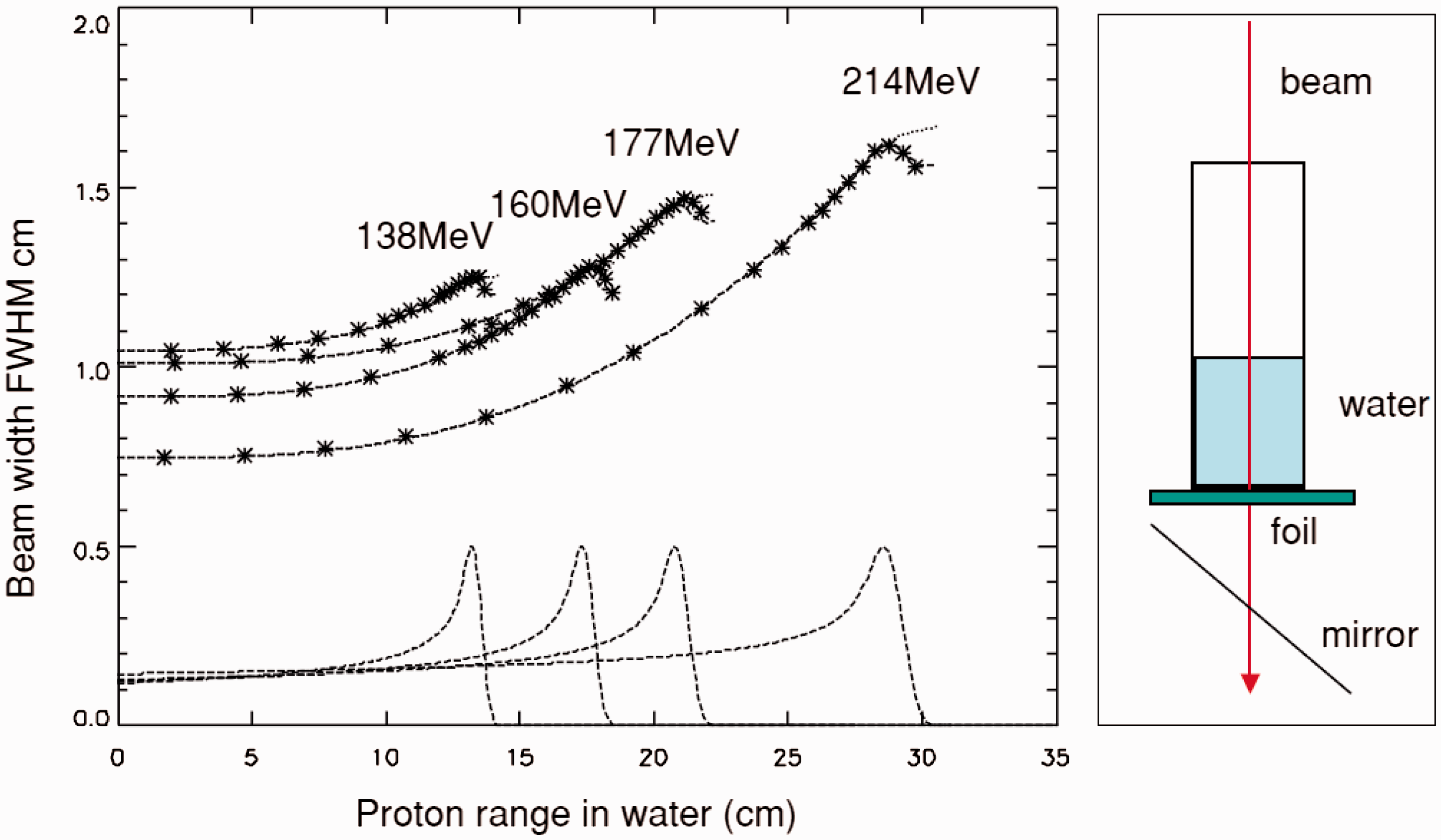
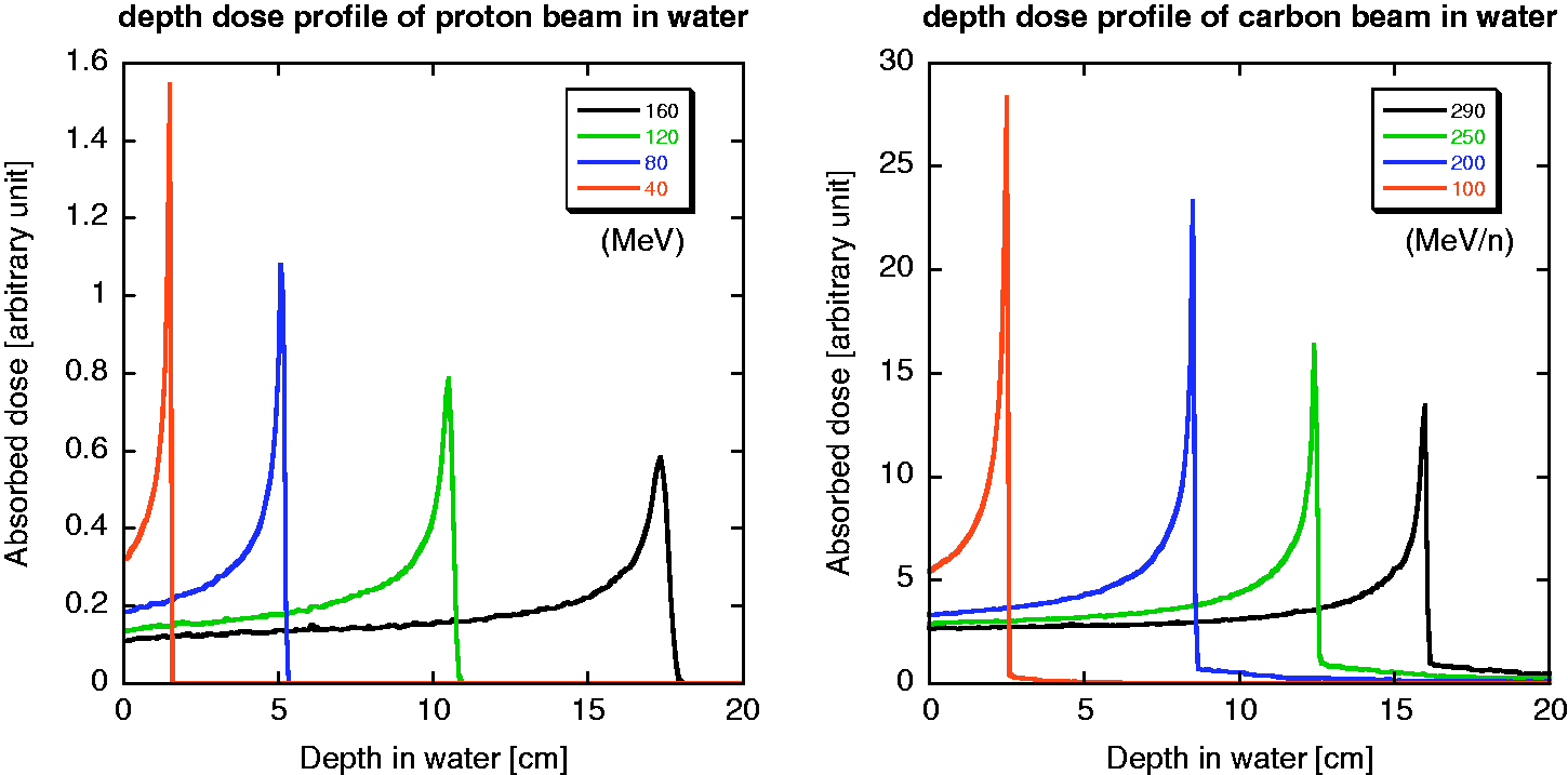
The calculated depth-dose distributions of proton and carbon ion beams in water, as obtained using the Particle and Heavy Ion Transport Code System (PHITS) (Iwase et al., 2002; Niita et al., 2006), are shown in Fig. 3.1. The peak-to-plateau ratio decreases due to the effects of fragmentation and straggling as the incident energy increases. Straggling also affects the broadening of the distal falloff. Approximately half of the total number of primary particles can reach the end of the range without experiencing fragment reactions (Matsufuji et al., 2005). The rest are broken into fragment particles. Among these, the fluence rates of hydrogen and helium tend to be comparable to those of primary carbon ions in the vicinity of the range end. In the case of proton beams, the projectile fragments are not involved in the beam; however, an increase in LET causes an enhanced biological effect at the very end of the range (Paganetti, 2003). This change in radiation quality should be considered for ion beam radiotherapy when estimating its biological or clinical effectiveness. The penumbra is often used to describe the sharpness of the beam spot after passing through a collimator (Kanematsu et al., 2006). The width of lateral falloff in the penumbra from 80% of the maximum dose to 20% is expressed as ‘P80–20’. The penumbra is composed of scattered primary particles in both proton and carbon ion beams, and of secondary charged particles in a carbon ion beam. In the case of a proton beam, the distribution is treated as a single Gaussian function (Pedroni et al., 2005), as shown in Fig. 3.2. A low-dose halo structure arises from a single or a few Coulomb scatterings. Inelastic scattering is practically negligible. For a carbon ion beam, the penumbra is approximated with three Gaussian distributions (Kusano et al., 2007). The abovementioned complex structure, especially that associated with a carbon ion beam, causes a change in radiation quality in the irradiation field when the field size is small (Nose et al., 2009). Lateral beam broadening of proton beam as a function of its kinetic energy. FWHM: full width at half maximum. Reprinted from Pedroni et al. (2005). Projected depth-dose distributions in water for protons with incident energies of 160, 120, 80, and 40 MeV (left), and for carbon ions with incident energies of 290, 250, 200, and 100 MeV n−1 (right) calculated using the Particle and Heavy Ion Transport Code System.
3.3.2. The out-of-field volume: secondary radiation
The out-of-field volume is characterised by secondary charged particles, as shown in the fragment tail and neutrons, which are released in nuclear reactions and distributed widely. Even in the in-field volume, particle fragments are involved in the therapeutic beam. However, most of the absorbed dose is delivered by primary particles. The effect of secondary particles becomes significant when no primary particle is present. In the case of treatment planning for carbon ion radiotherapy, attention should be paid to whether or not an OAR is present on the beam axis beyond the end of the range. Thus, the fragment tail is included in the beam kernel used in treatment planning for carbon ion radiotherapy. Apart from the fragment tail, the effect of heavy secondary charged particles is not significant. Neutrons and charged particles generated by them are a major concern when considering the dose outside the field. Due to their neutral charge, neutrons can scatter widely resulting in sparse energy density. As such, the effect of neutrons is, as a first approximation, considered to be negligible for the assessment of tumour control or acute radiation responses of normal tissue. The influence of neutrons concerns the development of late effects. The distribution of secondary neutrons is very different for proton and carbon ion beams. In carbon ion beams, neutrons can be emitted as both participants and spectators; this is not possible for proton beams as neutrons are not produced from the spectators. As the spectators retain their original motion from before the reaction, neutrons, as projectile fragments, have high energy and are strongly forward directed. Neutrons from target fragments and participants show a wide and isotropic distribution in the centre-of-gravity frame, and their energies are less than those of projectile fragments. The lack of projectile fragments as secondary neutrons in a proton beam characterises the quasi-isotropic distribution of neutrons, while the high-energy neutrons, in the forward direction, are added to the quasi-isotropic distribution in the case of the carbon ion beam. It should be noted that the distribution is greatly affected by the configuration of the beam line devices and the room design, as neutrons are produced in such devices and scattered throughout the whole room (Silari, 2001; Mesoloras et al., 2006; Tayama et al., 2006; Yonai et al., 2008; Zacharatou Jarlskog et al., 2008). Production data of secondary particles, in the range of ion beam radiotherapy, have been compiled in detail by Nakamura and Heilbronn (2006). The yield of neutrons increases as the incident energy or target mass number increases. Beam line devices such as collimators or ridge filters, made of heavier materials, are the main neutron production sources.
4. RADIOBIOLOGICAL IMPLICATIONS
The effect of ionising radiation is dependent on the absorbed dose, the dose rate, and the quality of radiation (ICRP, 2003b). In this section, the biological responses to radiation and health risks associated with radiation exposure are described. Specific issues associated with ion beam radiotherapy will be discussed in Section 5.
4.1. Interactions of radiation with DNA
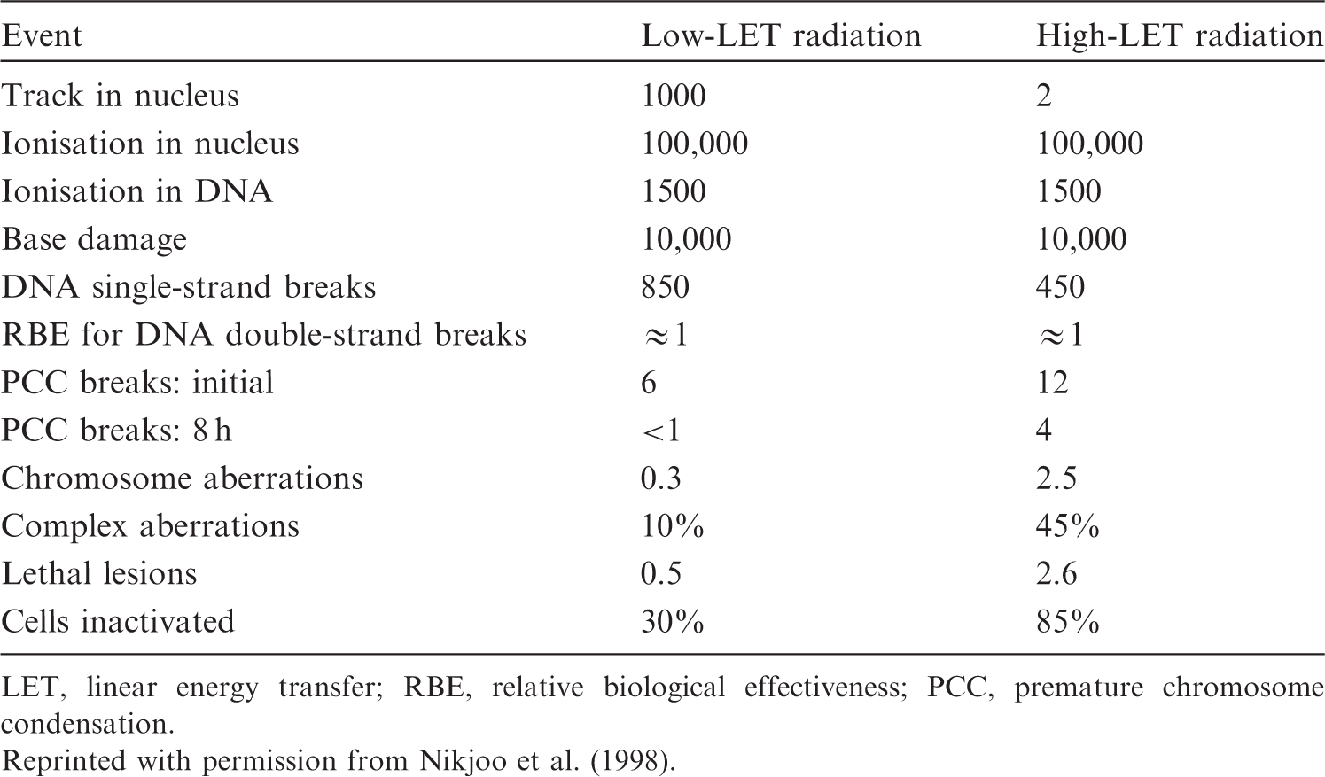
The critical target for biological effects of ionising radiation in biological cells is the DNA molecule, although extranuclear damage also plays a role. Ionising radiation produces DNA base change, single- and double-strand breaks by the direct deposition of energy or by an indirect reaction with radicals formed from the ionisation of water within a few nanometres of DNA. The approximate numbers of events in a mammalian cell after exposure to low-LET radiation vs high-LET radiation, for a dose of 1 Gy, are given in Table 4.1. Both qualities of radiation produce 100,000 ionisations in the nucleus. The numbers of initial chromosome aberrations are also similar; however, the resultant numbers of lethal-type chromosome aberrations differ markedly. This is because exposure to high-LET radiation gives rise to more complex structural damage, which is less easily repaired or the repair is more error-prone (Goodhead et al., 1993; Sutherland et al., 2001). This type of damage contrasts with DNA lesions arising spontaneously via oxidative radicals, which are distributed more randomly in DNA and have a simple chemical structure. Error-prone DNA damage can lead to gene mutations and chromosome aberrations. Average yield of damage in a single mammalian cell for an absorbed dose of 1 Gy. LET, linear energy transfer; RBE, relative biological effectiveness; PCC, premature chromosome condensation. Reprinted with permission from Nikjoo et al. (1998).
4.2. Health effects of ionising radiation
The health effects of radiation exposure can be classified into tissue reactions (deterministic effects) and stochastic effects. Tissue reactions result from cell killing, cell loss, or inflammation and are characterised by threshold doses. Stochastic effects are cancer induction and heritable effects. These result from genetic and epigenetic alterations, and are assumed to have no threshold dose.
4.2.1. Tissue reactions (deterministic effects)
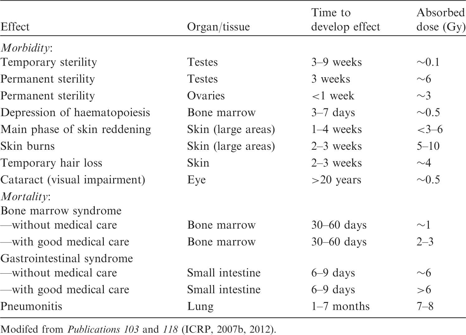
Radiation effects on normal tissue are grouped into early reactions (days to weeks) and late reactions (months to years). The principal factors that influence the incidence and severity of normal tissue damage are total dose, dose per fraction, fractional dose rate, time interval between fractions, overall treatment time, and dose–volume parameters. Clinical characteristics of early and late reactions and threshold dose are summarised in Table 4.2 (ICRP, 2007b). It should be noted that recent epidemiological evidence suggests that some tissue reactions have very late manifestation, where threshold doses are lower than previously considered, particularly for the lens of the eye and circulatory diseases (ICRP, 2012). Estimates of threshold dose for approximately 1% incidence of morbidity and mortality in adults exposed to acute irradiation. Modifed from Publications 103 and 118 (ICRP, 2007b, 2012).
Early tissue reactions
Early tissue reactions are expressed in rapidly proliferating tissues such as skin epithelium, gastrointestinal mucosa, gonads, and the haematopoietic system. These tissues have a hierarchical organisation with a proliferative compartment, with stem and progenitor cell populations, and a post-mitotic compartment of mature functional cells. The time course and types of injuries are dependent on the turnover rate of the specific cells and tissues. For example, the estimated lifespan ranges from a few days for granulocytes and the intestinal mucosa to more than 100 days for erythrocytes.
Late tissue reactions
Late reactions are expressed in slowly proliferating tissues, such as lung, heart, kidney, and the central nervous system, with the incidence of events still increasing with time, even more than 10 years after irradiation. Studies of atomic bomb survivors have shown an association between radiation and cardiovascular disease, stroke, digestive disorders, and respiratory disease a very long time after exposure. There is little evidence of excess risk for doses below 0.5 Sv (UNSCEAR, 2008). The lung is a sensitive organ for late tissue reactions in terms of fibrosis, and fibrosis is a dose-limiting disease when a large volume of the chest is irradiated. Late reactions in skin are characterised by thinning of the dermal tissue, telangiectasia, and the possibility of late necrosis, as distinct from skin epidermal reactions which are expressed as early tissue reactions. Cataract is defined as detectable changes in the transparency of the lens of the eye. Small opacities can be detected after acute doses of 0.5–2.0 Gy. The dose for 1% incidence of cataract with visual impairment was previously considered to be 5 Gy for acute exposure, but the value has been revised to 0.5 Gy by ICRP (2012). Evidence on circulatory disease has become available. An acute threshold dose of approximately 0.5 Gy was proposed for both cardiovascular and cerebrovascular diseases by ICRP (2012).
Volume effects
The volume of tissue irradiated is a critical determinant of clinical ‘tolerance’. There is a threshold volume of irradiation below which no functional damage of the whole organ is manifested, even after high radiation doses. The complication in normal tissue depends on the dose distribution and/or irradiated volume. Organs have been grouped into those with a parallel organisation (e.g. kidney and liver) and those with a serial organisation (e.g. intestine and spinal cord) (Withers et al., 1988). A serial organ loses its function when part of the organ is injured, but a parallel organ can retain its function due to its structure even if part of the organ is damaged. On the other hand, others consider physiologically and anatomically related effects, including the vasculature, to be more important in determination of the volume effect (Hopewell and Trott, 2004).
4.2.2. Stochastic effects
DNA damage to single cells can induce gene mutations or chromosome aberrations, which are critical for the induction of cancer and heritable diseases by radiation. For these effects, the probability of occurrence depends on the radiation dose. A general model used for radiological protection is that the risks for stochastic effects increase linearly with no threshold, and this is referred to as the ‘linear-non-threshold model’. Radiation-induced heritable risks have not been demonstrated in humans.
Cancers
Cancer dose–response relationships after acute low-LET radiation exposure can be fitted at doses below 2 Gy by a linear or a linear-quadratic (LQ) model for solid cancers and leukaemia, respectively. At higher doses, there may be a decrease or plateauing of the risk with increasing dose because of competing effects of mutation and cell killing. Second cancers found after radiotherapy with fractionated doses mainly develop after an accumulated dose of more than several tens of gray (Sachs and Brenner, 2005; Suit et al., 2007). Cancer risk due to radiation exposure is dependent on the tissues, gender, and age at exposure. Risk models suggest relatively large risk parameters for breast, lung, and colon (Preston et al., 2007). The detriment-adjusted nominal risk coefficient for cancer in the whole population is estimated to be 0.2% Sv−1. The inheritance of mutations of dominant tumour suppressor genes or DNA damage response genes may increase the probability of radiation-induced cancers. The risk of cancer development in individuals with these genetic disorders will be high, and additional risk is of concern at high doses during diagnosis and therapy using radiation. However, the presence of rare genetically susceptible subpopulations is too low to generate an acceptable distortion of the risk estimation in typical human populations (ICRP, 1998a, 2007b). In radiation therapy, optimisation requires not only the delivery of the prescribed radiation dose to the target volume, but also the protection of neighbouring normal tissue (ICRP, 2007d).
Heritable effects
Although there is no direct evidence in humans, there is evidence that radiation induces heritable effects in experimental animals. Publication 103 (ICRP, 2007b) provides the estimated hereditary risk up to the second generation of approximately 0.2% Sv−1.
4.3. Effects on embryos, fetuses, and children
Mammalian embryos and fetuses are highly radiosensitive during prenatal development (ICRP, 1991, 2007b; NCRP, 2013). Prenatal development is divided into three stages: pre-implantation (up to 10 days post-conception), organogenesis (3–7 weeks post-conception), and the fetal period. The risk of lethality to a developing organism is highest during the implantation stage. A dose of approximately 100 mGy produces significant pre-implantation deaths in mice after irradiation during the zygotic stage (Pampfer and Streffer, 1988). Radiosensitivity decreases with further fetal development. Malformations are mainly induced after irradiation during organogenesis. Exposure during the early development of the brain (8–15 weeks post-conception) may lead to severe mental retardation and a decrease in the intelligence quotient (IQ). The threshold dose for severe mental retardation is at least 300 mGy. Any effects on IQ following in-utero doses under 100 mGy would be of no practical significance (ICRP, 2007b). In-utero exposure was shown to increase the risk of all types of childhood cancer in the Oxford Study of Childhood Cancers (largest case–control study) (Bithell and Stewart, 1975). However, several cohort studies have found no clear evidence of an increase in radiation-induced childhood cancer (Boice and Miller, 1999; Schulze-Rath et al., 2008; Schonfeld et al., 2012). A recent report of atomic bomb survivors suggested that adult-onset cancer risk from in-utero exposure is lower than cancer risk following exposure in early childhood (Preston et al., 2008). Children are more susceptible to radiation than adults for some types of tumours (UNSCEAR, 2013). Late deterministic effects after radiotherapy (e.g. retardation of growth, hormonal deficiencies, organ dysfunction, and intellectual and cognitive functions) are more severe in children than adults (UNSCEAR, 1993, Annex I, p. 903). The prevalence of cataract increases with decreasing age at exposure (Nakashima et al., 2006). Young children are also susceptible to radiation induction of cancers. The excess risk of all solid cancers declines by 17% per decade of age at exposure (ICRP, 2007b, p. 197). It should be noted that children have distinctly different organ susceptibility from adults, with higher risk of thyroid and skin cancers but lower risk of lung cancer (Preston et al., 2007).
4.4. Radiobiological factors
Biological effects of ionising radiation are dependent on various factors including LET, track structure, energy, cell-cycle stage at irradiation, oxygen concentration, dose rate, and mode of dose fractionation.
4.4.1. LET and energy
The biological effect of radiation increases with increasing LET. The RBE of a particle relative to low-LET radiation reaches a maximum value at LET values of approximately 100–200 keV µm−1, depending on ion species. RBE is lower for higher LET values due to ‘wasted’ dose or ‘overkill’. This tendency is considered to be due to overt clustering of DNA lesions, with some cells experiencing cytoplasmic rather than nuclear damage, or no direct ionisation. In other cells, the amount of energy deposited by a single particle exceeds the amount required to kill the cell. Even for the same LET, the RBE is a function of the ion species. Thus, RBE increases as a function of LET (up to a maximum) for a specific particle, while RBE may even decrease with LET when comparing different particles. This fact demonstrates the limitations of the LET concept because the micro-structure of the energy deposition event, or track structure, is only roughly approximated by the LET concept. For neutrons, the biological effects are strongly dependent on neutron energy, being highest at ∼0.4 MeV (Hall et al., 1975).
4.4.2. Cell-cycle stage
For low-LET radiation, sensitivity varies depending on the stage in the cell cycle. The most radiosensitive phase is G2/M. Cells are resistant in the stationary phase and late S phase. Generally, dependence on the cell-cycle stage disappears when cells are irradiated with high-LET radiation, especially at low doses per fraction.
4.4.3. Oxygen
The response of cells to low-LET radiation is influenced by the cellular concentration of oxygen. This reacts with the radicals formed by hydrolysis to produce more reactive oxygen species. Hypoxic cells are 2.5–3 times more radio-resistant than well-oxygenated cells after exposure to low-LET radiation. OER is defined as the ratio of the absorbed dose required to cause the same biological endpoint in hypoxic conditions as in normoxic conditions. OER decreases with increasing LET. OER is close to unity for radiation with LET values greater than 200 keV µm−1 (Barendsen, 1968).
4.4.4. Dose rate and fractionation
With low-LET radiation, a reduction in the dose rate or multiple fractionation of the dose results in a reduction in the effects of a given dose of radiation. This is ascribed to the efficient repair of sublethal damage and cellular recovery. The therapeutic success of fractionation with low-LET radiation for many tumours lies in the difference in radiosensitivity and repair capability between tumour cells and cells in healthy tissues. As high-LET radiation produces more complex damage that is less easily repaired, the effects of dose fractionation and dose rate are smaller for high-LET radiation.
4.5. Relative biological effectiveness for ion beams and neutrons
High-LET radiation induces complex forms of DNA double-strand breaks that are difficult to repair and are effective in cell killing, as well as mutation induction, transformation, and cancer induction. The Commission introduced the radiation weighting factor, wR, for use in radiological protection to take into account the differences between the effects of different types of radiation (ICRP, 1991). In circumstances with radiotherapy using high-LET radiation, the relevant values of RBE are important for the effective treatment of cancer. Publication 92 reported an overview of RBE and wR (ICRP, 2003b).
4.5.1. RBE values for ion beam radiation in deterministic effects
RBE values are dependent on the dose deposition characteristics of the test radiation. For cell killing, at 10% cell survival doses determined using a colony forming assay, the RBE of helium and carbon particles increases up to a value of 3–4, being maximal at approximately 100 keV µm−1, and decreases for higher LET values (Ando and Kase, 2009). RBE values of less than 2 have been adopted for protons with energies of 50–2300 MeV, endpoints such as clonogenic cell survival, LD50/30, and intestinal crypt survival (Niemer-Tucker et al., 1999; ICRP, 2003b). The biological effect of protons for the cataractogenic effect is similar to that for photons, but the RBE for iron (190 keV µm−1) and argon (88 keV µm−1) rises to a value of 50–200 at low dose for the same endpoint (Brenner et al., 1993).
4.5.2. RBE for ion beam radiation in stochastic effects
RBE values are defined for a given endpoint and dose/level of effect. In contrast, radiation weighting factors (wR) used in radiological protection are defined as a conservative weighting factor for stochastic effects at low doses of radiation. Using the LQ formalism as the dose–response model, the RBE value reaches its maximum at an (imaginary) zero dose, then decreases gradually as the dose level increases. Thus, wR is related to the maximum RBE value. It should be emphasised that wR values are designed for the practice of radiological protection, not for specific risk assessment (ICRP, 2003b, p. 30). There is good concordance between DNA double-strand breaks, especially complex clustered damage, and radiation-induced gene or chromosome mutations. In general, the dose–response relationship for mutation induction is LQ for low-LET radiation, and tends towards a linear relationship for high-LET radiation. The maximum RBE values are approximately 20–40 for particles with LET in the range of 50–70 keV µm−1 (Edwards, 1997; ICRP, 2003b, p. 61). RBE values for the induction of in-vitro neoplastic transformation in C3H10T1/2 cells increase up to a value of approximately 10 for LET of 100–200 keV µm−1 (Yang et al., 1985, 1996). RBE values for 14, 30, and 172 keV µm−1 carbon ions for transformation of HeLa X human skin fibroblast cell line CGL1 are 1.0, 2.5, and 12, respectively (Bettega et al., 2009). No data exist regarding the effects of ion beams that relate to stochastic effects in humans. Thus, risk estimates are derived from experiments on animals. The RBE value for 60-MeV protons, with an average LET of 1.5 keV µm−1, compared with 300-kV x rays, does not exceed 1.0 for shortening of lifespan and tumour induction in mice (Clapp et al., 1974). A wR value equal to 2.0 is recommended for protons (ICRP, 2007b). RBE values for iron ions with LET of 193 keV µm−1 and 253 keV µm−1 are 40 and 20, respectively, for the induction of Harderian tumours (Alpen et al., 1993). This indicates that a single wR value for heavy ions is not appropriate. RBE values for ion beams are dependent upon the dose range used, and are higher for lower doses (Fry et al., 1985; Imaoka et al., 2007). They are also tissue dependent, with a small value for leukaemia (IARC, 2000, p. 430). Although the Commission considers that the selection of a single value of wR is an oversimplification, wR = 20 is recommended for α particles, fission fragments, and heavy ions.
4.5.3. RBE for neutrons for stochastic effects
The RBE of neutrons varies significantly with energy. The most effective neutron energy for producing chromosome aberrations in human lymphocytes is 0.4 MeV (Schmid et al., 2003). The RBE value, compared with 60Co γ rays as reference radiation, is close to 100 (ICRP, 2003b). The RBE value for oncogenic transformation increases from 3.7 for 40 keV of neutrons to 7.2 for 350 keV of neutrons (Miller et al., 2000). The RBE values for mouse epithelial tumour induction are reported to be 20–30. The recommended wR is represented as a continuous function, with the maximum value of 20 at 1 MeV. Based on the RBE values for stochastic effects, wR values proposed by the Commission for each type of radiation are given in Table 4.3. It should be noted that values of wR are given for the radiation incident on the human body or, for internal radiation sources, emitted from the incorporated radionuclide, and are therefore independent of the organ or tissue considered. Recommended radiation weighting factors (wR) (ICRP, 2007b). All values relate to a radiation incident involving the body or, for internal radiation sources, emitted from the incorporated radionuclide(s). Note the special issue of Auger electrons discussed in Section B.3.3 of Annex B in Publication 103 (ICRP, 2007b).
4.5.4. RBE for fetuses and children
With regard to intra-uterine lethality, malformation, and growth retardation in animal experiments, RBE values for high-LET radiation have been proposed to be approximately 3 (ICRP, 2007b). No adequate human in-utero and childhood exposure data are available to determine RBE values for ion beams for tissue reactions and stochastic effects.
5. RADIATION EXPOSURES IN ION BEAM RADIOTHERAPY
5.1. Medical exposure of patients from therapeutic irradiation
5.1.1. In-field treatment volume
The use of an ion beam greatly reduces the entrance dose due to its physical depth-dose characteristics (i.e. the Bragg peak) compared with the photon and electron beams used in conventional radiotherapy. In addition, a carbon ion beam has physical and biological characteristics that differ from proton beams: a lower scattering power, and a higher RBE value in the SOBP region. By using these characteristics, treatment planning in ion beam radiotherapy theoretically achieves a potentially curative radiation dose that has to be delivered to the target volume. Simultaneously, undesired exposure of normal tissue is reduced in comparison with conventional radiotherapy. The in-field dose is considered in the treatment planning of each patient in view of side effects (deterministic effects), whereas the out-of-field dose is not usually considered. The method and process of treatment planning in proton radiotherapy were described in ICRU Report 78 (ICRU, 2007). The treatment planning is essentially the same in both proton and carbon ion radiotherapy. There is a trade-off between dose escalation and the higher conformity required in the target volume for tumour local control and the dose or dose–volume constraints when considering the radiation toxicity in radiotherapy (Marucci et al., 2004; Tsuji et al., 2005, 2008; Kawashima et al., 2011). The dose distribution and dose–volume histogram often play an important role in finding the best treatment plan based on clinical dose escalation studies (Kamada et al., 2002; Mizoe et al., 2004). The ratio of the Bragg peak absorbed dose vs the entrance absorbed dose is higher for carbon ions than for protons. However, as RBE is dose dependent (more significant for heavier ions), lower doses outside the target, depending on their LET values, have to be scaled with a higher RBE value at biologically equivalent doses (ICRP, 2003b). Nevertheless, the price to be paid for this potential advantage of lower peak/plateau ratio when using carbon ions is the creation of fragments causing residual dose just after the Bragg peak. This phenomenon is negligible for protons. Palm and Johansson (2007) compared conventional radiotherapy, IMRT, and proton radiotherapy with respect to the conformity index and dose distributions in the target volume, OARs, and non-target tissues, based on published treatment planning studies. They also studied published measurements and Monte Carlo simulations of the out-of-field dose distributions, and clearly demonstrated that a more favourable dose distribution could be obtained in OARs and non-target tissue using proton radiotherapy compared with IMRT. IMRT and proton radiotherapy have a similar ability to improve the dose distribution in the target volume, which may increase the probability of tumour control, as well as dose conformity, compared with conventional radiotherapy. Both forms of treatment also reduce the maximum dose to OARs. Palm and Johansson (2007) also noted that the size of the penumbra has a large impact on dose conformity in the target and on the maximum dose to OAR volumes adjacent to the target volume. This means that carbon ion radiotherapy can reduce the maximum dose to OARs because a carbon ion beam has a lower scattering power. An example, showing a comparison of the dose distributions with IMRT and carbon ion (broad beam method) radiotherapy treatment plans for cancer of the parotid gland, is shown in Fig. 5.1. The target volume (cyan line) is almost totally covered by the 95% isodose line (red line) in both plans. The dose convergence in the low-dose region in the plan for carbon ion radiotherapy is superior to that for IMRT. These reductions in undesired exposure can lead to reduced side effects in OARs. The undesired exposure dose near or in the irradiation field depends on the treatment planning of each patient, but still follows the conclusions given above, even using the broad beam method. Comparison of dose distributions in treatment plans for intensity-modulated radiotherapy (IMRT) and carbon ion radiotherapy, using the broad beam method, for cancer of the parotid gland. (a) Plan for IMRT. (b) Plan for carbon ion radiotherapy.
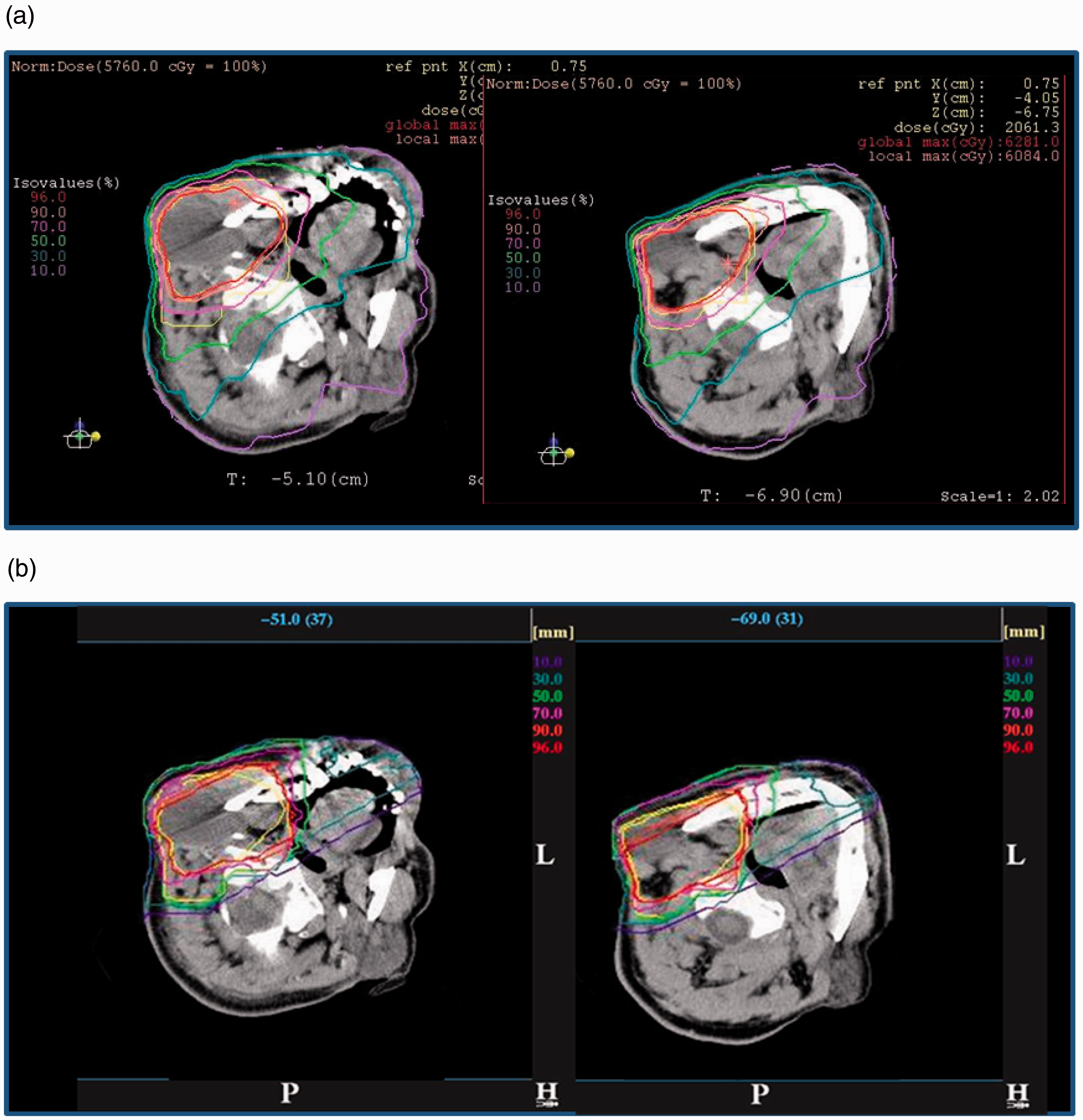
5.1.2. Out-of-field volume
Ion beam radiotherapy should emerge as a useful irradiation treatment technique, deliver high doses in a very limited and well-defined volume, while sparing most of the rest of the body. However, the type of beam delivery (i.e. broad or scanning beam) may influence the dose at a distance outside the target volume (Hall, 2006).
Which types of radiation influence the dose in the out-of-field volume?
The simulated partial contributions to the total absorbed dose in a Lucite phantom from protons, neutrons, and photons in proton radiotherapy for prostate cancer are shown by Clasie et al. (2010). There is a large proton contribution to the total dose at a distance less than 10 cm from the field edge, due to primary protons, regardless of the irradiation method. Also, protons scattered by the final collimator make a 10–15% contribution to the total dose at a distance greater than 15 cm from the field edge in a beam produced by the broad beam method. The photon dose contribution increases with distance from the field edge; for example, to 60% at 60 cm from the field edge by the scanning method. However, after considering their higher biological effectiveness, the largest fraction of the total equivalent dose is due to neutrons at a distance greater than 10 cm from the field edge. There are two components to the secondary neutrons produced in ion beam radiotherapy: (i) neutrons produced in the patient (internal neutrons); and (ii) neutrons produced in the beam line devices (external neutrons). Internal neutrons are an inevitable dose component with the use of both broad and scanning beam methods because they are produced by interactions of the charged particles that deliver the potentially curative dose to the target volume. External neutrons are produced in nuclear reactions with primary charged particles in beam line devices. The distribution of the proton and neutron flux for prostate treatment using double-scattering proton radiotherapy, obtained using Monte Carlo simulation, are shown in Fig. 5.2 (Fontenot et al., 2008). All beam line devices, which the primary charged particles inevitably enter, become a source of external neutrons. The dose contribution from neutrons, produced in each device, to the total dose to the patient depends on the location, the material of the device, the configuration, and the number of primary particles that enter the device. Such dependence is discussed in detail below. Several investigations, using Monte Carlo simulations, have been undertaken to evaluate the contribution of internal and external neutrons to the total dose for prostate and lung cancer treatments in proton radiotherapy using the broad beam method (Jiang et al., 2005; Fontenot et al., 2008; Zacharatou Jarlskog et al., 2008; Taddei et al., 2009). Internal neutrons were shown to contribute significantly to the dose near the target irradiation volume, while external neutrons became the main contributor to organ doses further away from that volume. Fontenot et al. (2008) calculated equivalent doses in each organ using Monte Carlo N-Particle eXtended (MCNPX) simulations (Pelowitz, 2008), assuming the beam characteristics of the passive scattering nozzle used at the M.D. Anderson Proton Therapy Center. For a simulated prostate treatment, external neutrons accounted for more than 98% of the neutron equivalent dose for organs, such as the oesophagus and thyroid, distant from the treatment volume. On the other hand, approximately 40% of the neutron equivalent dose was attributed to internal neutrons for organs near the treatment volume, such as the bladder, rectum, and gonads. The dose distribution from neutrons depends on the body size (Zacharatou Jarlskog et al., 2008; Athar and Paganetti, 2009). Yonai et al. (2009) calculated the proportional contribution of neutrons, produced in each beam line device, and a water phantom to the ambient dose equivalent on the treatment couch in carbon ion radiotherapy at the Heavy Ion Medical Accelerator in Chiba (HIMAC) using the PHITS code (Iwase et al., 2002; Niita et al., 2006). The main source was external neutrons (those produced in components other than water), which was the same as in proton radiotherapy. The contribution of internal neutrons to the total neutron ambient dose equivalent was only 10% at 25 cm from the beam axis. The contribution decreased with distance from the beam axis. These results clarified that neutron exposure in ion beam radiotherapy was lower with the scanning method than with the broad beam method. This is because the number of external neutrons produced was smaller for the scanning method compared with the broad beam method. In carbon ion radiotherapy, the fragmented charged particles produced by the incident carbon beam are also a contributor to the dose at a position close to the irradiation volume. Their characteristics are discussed in Section 3. In the current TPS, dose in the fragment tail region is considered. On the other hand, the lateral distribution of the lighter fragmented particles, such as protons, is not simulated accurately because of the higher scattering power, including a lateral ‘kick’ at the point of production of fragments (Kanai et al., 2004; Matsufuji et al., 2005; Kusano et al., 2007). Although the dose is considerably lower than that from the primary particles, it is necessary to include laterally distributed fragmented charged particles for dose assessment in the out-of-field volume in carbon ion radiotherapy. Distributions of the proton (top) and neutron (bottom) flux for a prostate treatment using double-scattering proton radiotherapy, obtained using Monte Carlo simulation. A proton pencil beam (A) enters through a vacuum window and traverses a profile monitor (B). The rotating range modulator wheel (C) and second scatterer (D) spread the beam longitudinally and laterally. Also modelled are the range shifter (E), main and subdose monitors (F), and the snout, which contains the patient-specific aperture (G) and range compensator (H). Units are particles per cm2 per incident proton. Reprinted from Fontenot et al. (2008).
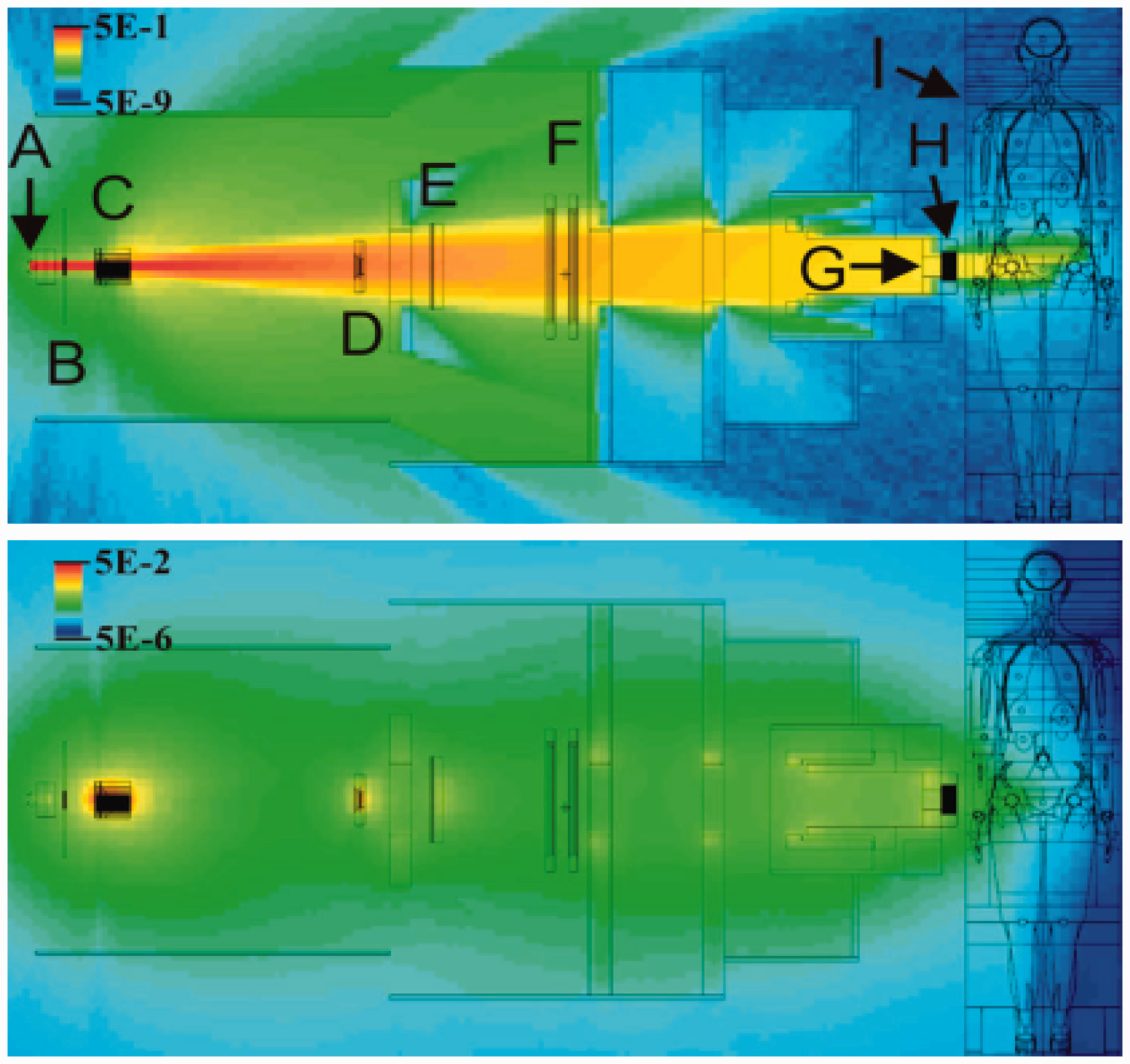
What influences the production of secondary neutrons?
Beam line devices The fluence, energy spectrum, and angular distribution of secondary neutrons from nuclear reactions with ion beams depend on the energy and the species of the incident particles and the target nuclei, as described in Section 3. In addition, the secondary neutrons are moderated or shielded by the beam line devices. Therefore, the neutron dose at the patient position depends on the material, the location, and the configuration (thickness and shape, etc.) of each beam line component and their relationship (i.e. the design of the beam delivery system). The neutrons produced in collimators are the predominant component of the external neutron dose in irradiation using the broad beam method. This is because the collimators are located close to the patient, and many primary particles stop at this location in the beam line (Brenner et al., 2009; Yonai et al., 2009; Hecksel et al., 2010). Installation of a pre-collimator has a considerable impact on reducing the secondary neutron dose (Zheng et al., 2007; Brenner et al., 2009; Yonai et al., 2009). The pre-collimator allows a flexible arrangement in the beam delivery system compared with the final collimator. This is because the pre-collimator has little effect on the treatment beam, such as the beam penumbra. If it is far from the patient and can be increased in thickness, the production of secondary neutrons can be moderated or shielded. Brenner et al. (2009) and Yonai et al. (2009) also showed that using collimators made of a material with a greater shielding effect, such as nickel, reduced the secondary neutron dose effectively. Other components that influence secondary neutron production are range-shifting and range-modulating devices. Using MCNPX simulations, Polf and Newhauser (2005) calculated the fraction of dose equivalent due to neutrons produced by a Lucite range modulation wheel (RMW), a final brass collimator, and a Lucite phantom 50 cm downstream from the isocentre, along the beam axis with increasing RMW step thicknesses (thicknesses of the Lucite slab assuming the RMW), assuming the characteristics of a beam line in the Harvard Cyclotron Laboratory. This study indicated that neutrons produced in range-shifting and range-modulating devices make a greater contribution to the dose to the patient when the range shifter is thicker and/or the SOBP width is larger. More consideration regarding the influence of these devices is needed in proton radiotherapy compared with carbon ion radiotherapy, because the beam delivery system in proton radiotherapy is shorter than that in carbon ion radiotherapy due to the higher scattering power. Shielding methods to reduce the neutron dose to patients have been proposed by Taddei et al. (2008) and Yonai et al. (2009). Beam parameters The influences of beam parameters have been investigated by several groups (Polf and Newhauser, 2005; Mesoloras et al., 2006; Zheng et al., 2007; Yonai et al., 2008; Zacharatou Jarlskog et al., 2008; Athar and Paganetti, 2009; Shin et al., 2009; Hecksel et al., 2010). The following parameters are considered to have the main effects on the neutron dose to patients in ion beam radiotherapy using the broad beam method.
Beam energy. The total number of neutrons definitely increases with increasing energy because their path becomes longer and therefore the likelihood for reactions increases. As a result, the neutron absorbed dose per therapeutic dose increases with the energy of the primary beam. SOBP width. As the modulator is thicker, the number of external neutrons increases because primary particles have more nuclear reactions and lose more energy in the range modulator. When the width of the SOBP is increased, more primary particles are needed to deliver a prescribed dose to a target volume. Thus, the total neutron dose from internal neutrons per target dose increases with SOBP width. Position of the snout or beam nozzle (distance between the final collimator and the treatment isocentre). The neutron dose decreases as the snout position is located further away from the patient because the neutron source is further away from the patient. Beam size (defined as the size of a laterally uniform field produced by the double-scattering or wobbler-scattering methods). The neutron dose component in the target dose increases as the beam size increases when the aperture size is fixed. This phenomenon is observed regardless of the technique used to make a laterally uniform field (i.e. the double-scattering or wobbler-scattering method). This is largely because more primary particles are needed to deliver a prescribed dose to a target volume when the beam size is larger. Aperture size (determined by aperture size of the collimators, and almost equivalent to the beam size irradiated to the patient when excluding beam divergence). The number of external neutrons decreases and the number of internal neutrons increases as the aperture size is increased when the beam size is fixed. This is because the number of primary particles entering the final collimator decreases, and the number of primary particles entering the patient increases. Consequently, the total neutron dose would change depending on the fraction of the contribution of internal and external neutron doses. The beam parameters are determined by treatment planning, and the snout position is determined geometrically. Usually, the snout is as close to the patient as possible to minimise the size of the penumbra. Therefore, using the broad beam method, the only way to reduce the external neutron dose is to minimise the beam size (and therefore maximise beam efficiency). Yonai et al. (2008) showed that this approach reduces the neutron dose effectively. However, in practice, it is laborious to minimise the field size for each patient, because it is necessary to manage a large number of sets of beam parameters and to install numerous scatterers when using a double-scattering method. A practical approach is required; for example, the use of several beam sizes such as small, medium, and large. The parameters in the scanning method that have the main effect on the neutron dose to patients are beam energy and the number of primary particles, because the number of external neutrons produced with the scanning method is much smaller compared with the broad beam method.
How much is the dose in the out-of-field volume?
Measurements and calculations of out-of-field doses for proton radiotherapy have been reported (Xu et al., 2008). The dose equivalent for neutrons, as a function of distance to the field edge for proton radiotherapy, is shown in Fig. 5.3. Three studies [Yan et al. (2002) (measurements with Bonner sphere), Polf and Newhauser (2005) (Monte Carlo simulation with MCNPX), and Zheng et al. (2007) (Monte Carlo simulation with MCNPX)] have assessed the in-air neutron dose equivalent for proton radiotherapy using the broad beam method. Schneider et al. (2002) measured the in-air neutron dose equivalent with a rem meter for a scanning proton radiotherapy beam, except for one measured point close to the field edge where the neutron dose equivalent was measured using CR-39 in a water phantom. The other three studies only investigated the in-phantom dose. Ambient neutron dose equivalents measured in air tend to show higher values compared with the neutron dose equivalent in a phantom, as shown in Fig. 5.4. However, in-air data are helpful to understand differences between different facilities and different irradiation techniques. Although there are differences in the beam parameters and the experimental and calculation geometry used to establish the results, it is confirmed that the neutron dose in ion beam radiotherapy with the scanning method is significantly less than that with the broad beam method because the number of external neutrons is small or insignificant. Yonai et al. (2008) measured the neutron ambient dose equivalent at the patient position in four proton radiotherapy facilities in Japan with approximately the same parameter settings of beam-shaping devices and exactly the same experimental setup in order to investigate the facility dependence of the neutron dose (Fig. 5.5). This study showed that the variation by facility dependence was within a factor of three, regardless of the method used to make the uniform irradiation field (i.e. double-scattering or wobbler-scattering methods). Facility dependence was derived for two components: differences in the beam line devices; and differences in the operational beam parameters used in routine treatment, especially the field size, as noted above. It was also found that the neutron dose in carbon ion radiotherapy is less than that in proton radiotherapy, when the beam parameters are the same, for the broad beam method. Gunzert-Marx et al. (2008) at GSI measured the energy spectra, angular distributions, and yields of secondary charged particles and fast neutrons produced by 200 MeV n−1 12C ions, stopping in water. The absorbed dose outside the treatment volume due to neutrons was estimated to be less than 1% of the treatment dose. The level of the neutron doses in proton radiotherapy is similar to that in carbon ion radiotherapy, although the neutron yield is much higher for carbon ions. This is explained by the fact that a much higher number of protons is needed to produce the same target volume dose compared with carbon ions. Organ-specific information on the absorbed dose and biological effectiveness in the patient is essential for assessing risks, because secondary neutrons are the main component of the out-of-field dose, and the undesired dose is not distributed uniformly in the human body. However, at present, there are only a few studies related to this issue in comparison with in-air dose assessment. Measurements were generally made using a microdosimetric technique to obtain the lineal energy distributions (Wroe et al., 2007, 2009; Yonai et al., 2010), which are related to biological effectiveness. Calculations were carried out using a computational anthropomorphic phantom and Monte Carlo codes such as Geant4 (Agostinelli et al., 2003), FLUKA (Fasso et al., 2005), MCNPX (Pelowitz, 2008), PHITS (Iwase et al., 2002; Niita et al., 2006), and SHIELD-HIT (Gudowska et al., 2004). Wroe et al. (2007, 2009) measured the dose-averaged quality factor (QD) and dose equivalent (H) in proton fields obtained using the broad beam method at the Loma Linda University Medical Center for various clinical treatments, using a silicon-on-insulator microdosimeter and either an anthropomorphic phantom or a block phantom made of Lucite or polystyrene. With the broad beam method, Yonai et al. (2010) measured QD and H in the proton field and in the carbon ion field at the National Cancer Center Hospital East. For this, a tissue-equivalent proportional counter and a water phantom were used. For the 235-MeV proton beam, the measured H per treatment absorbed dose and QD obtained by Wroe et al. (2007, 2009) and Yonai et al. (2010) are compared in Fig. 5.4. It should be noted that other types of radiation as well as neutrons contribute to these dose equivalents and quality factors. H is lower as the location moves further from the beam axis and on the upstream side of the phantom. H measured by Yonai et al. (2010) was two to three times higher than the results of Wroe et al. (2007, 2009). This should be attributed to facility dependence as discussed above. QD is higher at lower water-equivalent depth because the contribution of secondary neutrons produced in the beam line devices with a high quality factor is higher. As the position is closer to the field edge (within ∼20 cm from the field edge), QD is decreased by two, mainly due to the scattered incident protons. From these results, the following conclusions for a 235-MeV proton beam were drawn: QD is 2–5 at a position within ∼20 cm from the field edge; QD is 7–8 at a position close to the beam line devices; and QD is 5–6 at other positions. It is expected that these values depend slightly on beam energy, as shown below. Measured H, per treatment absorbed dose, and QD for the 400-MeV n−1 carbon ion beam at HIMAC are shown in Fig. 5.6 (Yonai et al., 2010). H is lower as the location moves further away from the beam axis and on the upstream side of the phantom. QD is lower as the location moves closer to the beam axis, but does not depend on off-axis distance. The fragmented charged particles, especially protons, that are generated in the patient strongly influence H and QD at locations close to the field edge. QD is 2–4 within ∼50 cm from the field edge, and QD is relatively constant between 4 and 5 at other locations. In both proton and carbon ion beams, H is higher and QD is constant or slightly lower as the incident beam energy is higher (Wroe et al., 2009; Yonai et al., 2010). Several studies have used computational anthropomorphic phantoms and Monte Carlo simulations to calculate organ doses for proton radiotherapy. Jiang et al. (2005) used the Geant4 code to simulate an adult male, VIP Man, using two proton radiotherapy treatment plans for lung and paranasal sinus cancers. To calculate equivalent dose to each organ, the absorbed dose in each voxel was accumulated, and the neutron fluencies and energies at the surface of each organ were stored to be used for calculating the average neutron radiation weighting factor based on Publication 60 (ICRP, 1991). Mesoloras et al. (2006) used a bubble detector and an anthropomorphic phantom to experimentally evaluate the neutron dose equivalent to a representative point for the fetus of a mother receiving proton radiotherapy using the broad beam method. Their results are included in Fig. 5.3. In practice, a bubble detector can only measure the absorbed dose, not the biologically effective dose. They used the average neutron quality factor derived by Jiang et al. (2005) based on Monte Carlo calculations. Zacharatou Jarlskog and Paganetti (2008) used the Geant4 code to assess and compare organ doses for paediatric and adult patients. It was shown that paediatric patients would receive higher organ equivalent doses than adults from neutrons generated in the treatment head, because younger patients have smaller body sizes. The equivalent doses for 15 organs, averaged over all fields, as a function of phantom age (i.e. patient’s age) are shown in Fig. 5.7. The doses vary more significantly with patient’s age for organs further away from the target volume. Monte Carlo simulations are a necessary tool to assess organ-specific doses and change in the dose with beam parameters. However, because experimental data are scarce, as noted above, experimental verification of Monte Carlo simulations is limited. Additional experimental data are required for accurate dose estimation. As the secondary neutron dose is facility dependent, it is desirable that each facility should measure the secondary neutron dose to the patient. For this purpose, measurement of the ambient dose equivalent with a rem meter is convenient; its values may indicate the maximal secondary dose in phantoms, as shown in Fig. 5.4. Careful consideration of dead time and signal pile-up in the measurement is required, especially for a pulsed beam. As the neutron dose depends on the beam parameters and measurement setup, standardisation of these measurements is needed. In addition, a critical level is needed for proton and carbon ion radiotherapy similar to dose reference levels for diagnostic procedures. Further discussions are needed to establish regulation and the critical level. Equivalent dose as a function of phantom age (i.e. patient’s age) averaged over all fields. (a) Lens of the eye (closed circles), thyroid (open squares), thymus (closed triangles), and lungs (open diamonds). (b) Oesophagus (closed circles), heart (open squares), liver (closed triangles), and stomach (open diamonds). (c) Spleen (closed circles), gall bladder (open squares), adrenals (closed triangles), and pancreas (open diamonds). (d) Kidneys (closed circles), small intestine (open squares), and bladder (closed triangles). Reprinted from Zacharatou Jarlskog and Paganetti (2008). Measured absorbed dose per treatment absorbed dose at the centre of the range-modulated region, D/Dt, dose equivalent per treatment absorbed dose at the centre of the range-modulated region, H/Dt, and dose-averaged quality factor, QD, for the 400-MeV n−1 carbon beam. (a) D/Dt and H/Dt on the line d = 20 cm. (b) QD on the line d = 20 cm. (c) D/Dt and H/Dt on the line x = 25 or 50 cm. (d) QD on the line x = 25 or 50 cm. Error bars represent the statistical error. Reprinted from Yonai et al. (2010). Measured ambient dose equivalent in proton and carbon radiotherapy using the broad beam method. The legend shows the beam species, energy, and facility. P, beam species of protons; C, beam species of carbon ions; number following ‘p’ or ‘C’ indicates beam energy in MeV n−1; PMRC, Proton Medical Research Center at Tsukuba University; NCCHE, National Cancer Center Hospital East; SCC, Shizuoka Cancer Center; HIBMC, Hyogo Ion Beam Medical Center; HIMAC, Heavy Ion Medical Accelerator in Chiba. Modified from Yonai et al. (2008). Comparison of measured H values per treatment absorbed dose at the centre of the range-modulated region, H/Dt, and QD by Wroe et al. (2007, 2009) and Yonai et al. (2010) for the 235-MeV proton beam. Here, the Q(y)-y relationship from ICRU Report 40 (ICRU, 1986) was used in both studies. WED, water-equivalent depth of the measured position. (a) Dose equivalent per treatment absorbed dose at the centre of the range-modulated region, H. Measured neutron ambient dose equivalents, H*(10)/Dt obtained with the rem meter WENDI-II are also shown (Yonai et al., 2008). (b) Dose-averaged quality factor, QD. The error bar represents the standard deviation. Neutron dose equivalent as a function of distance to the field edge reported by three different proton experiments (Yan et al., 2002; Wroe et al., 2007; Mesoloras et al., 2006) and two sets of Monte Carlo simulations using passive scattering techniques (Polf and Newhauser, 2005; Zheng et al., 2007). Monte Carlo simulations by Zacharatou Jarlskog et al. (2008) show neutron equivalent doses. Also included are data from proton beam scanning (Schneider et al., 2002). Due to the significant dependence of neutron doses on beam parameters in proton therapy, two curves are shown from each publication to represent the best- and worst-case scenarios. Reproduced from Xu et al. (2008).
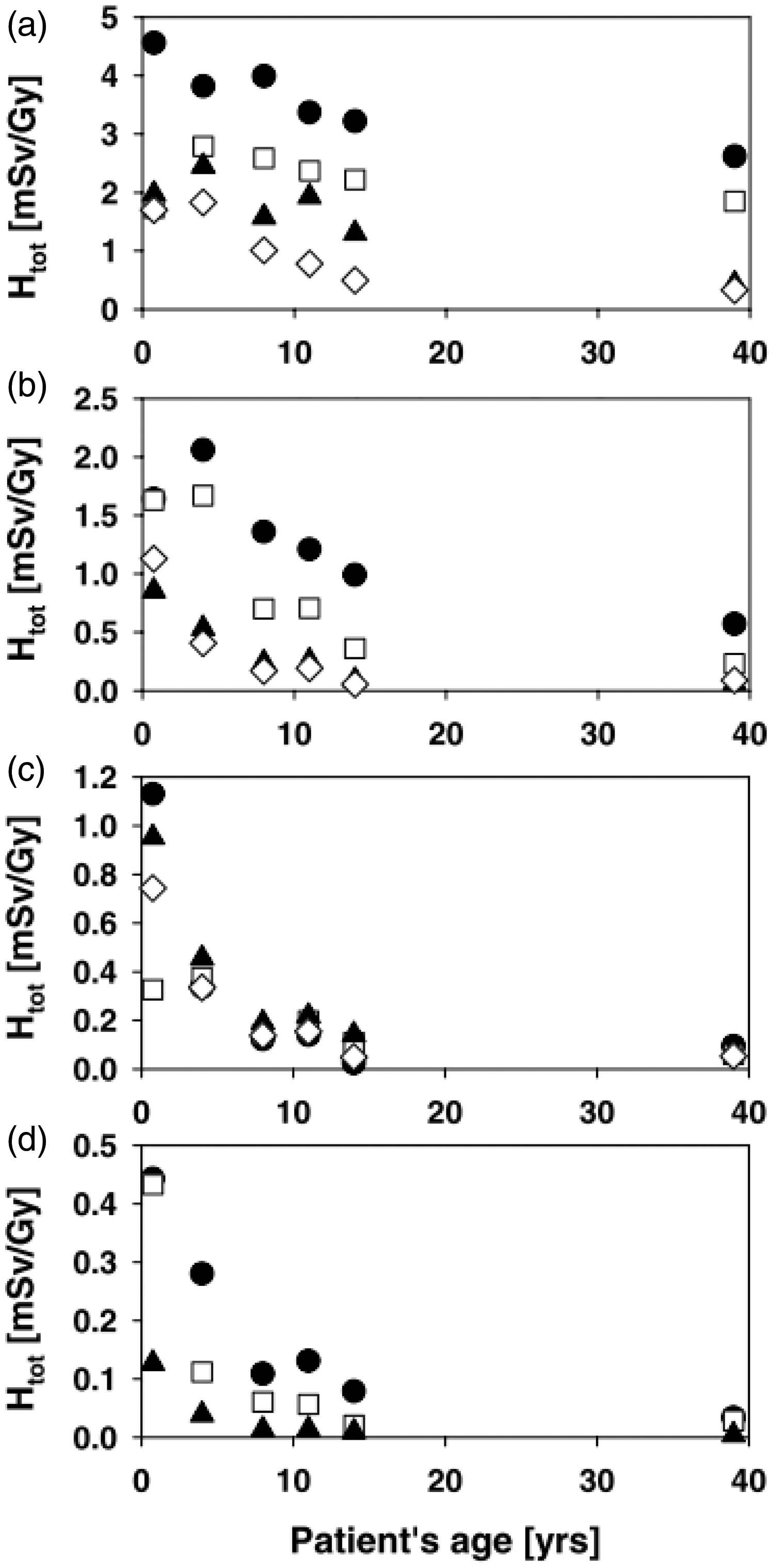
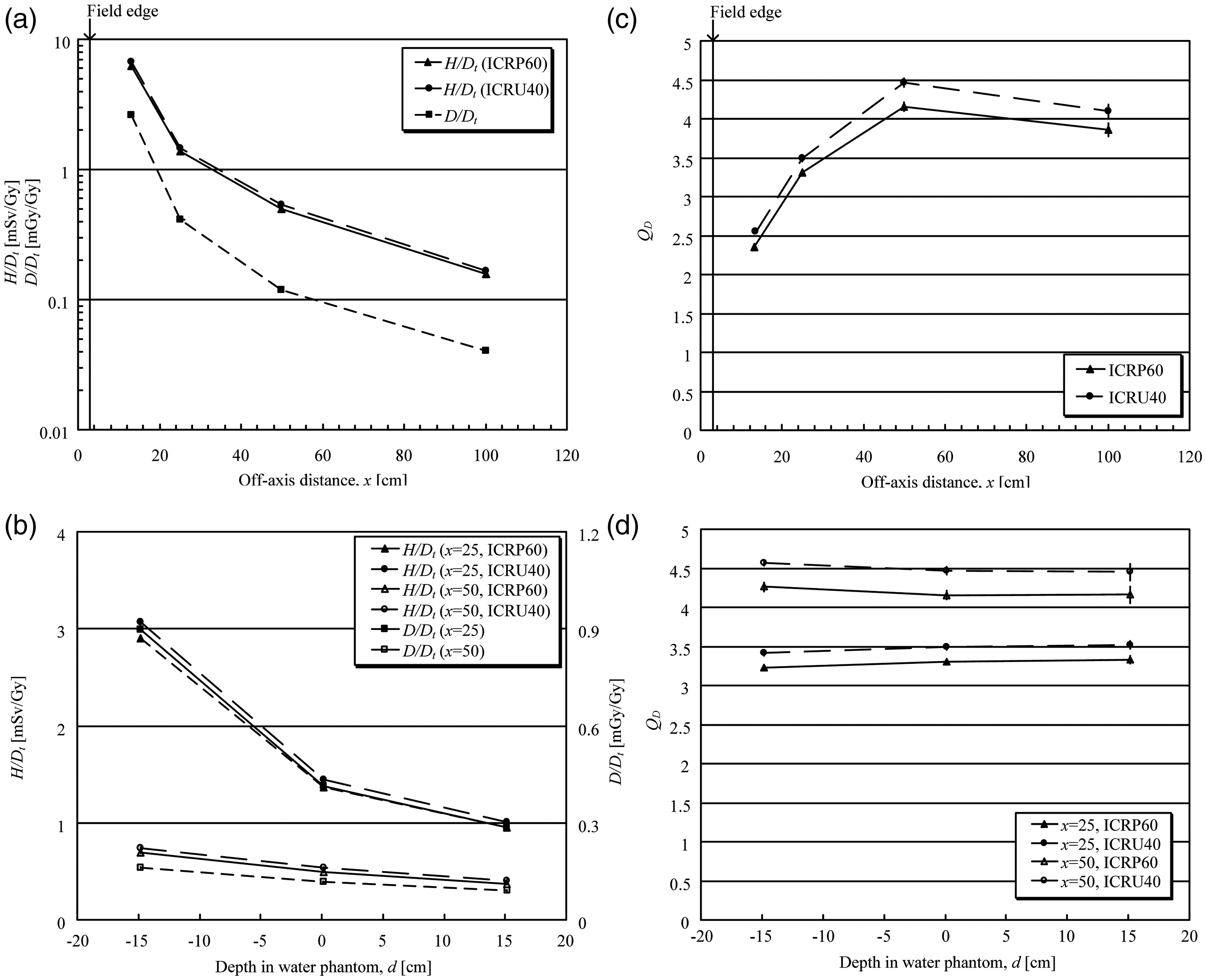
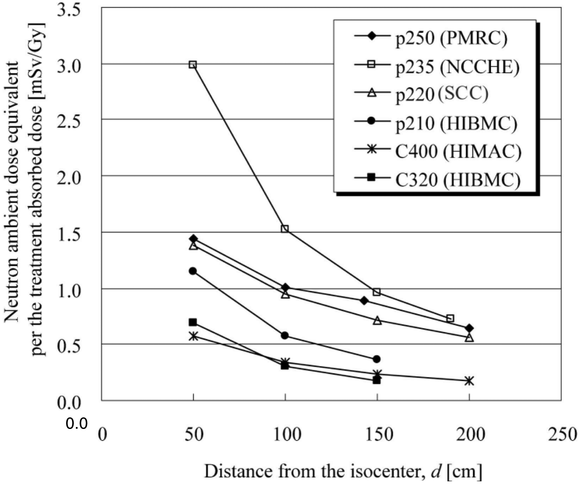
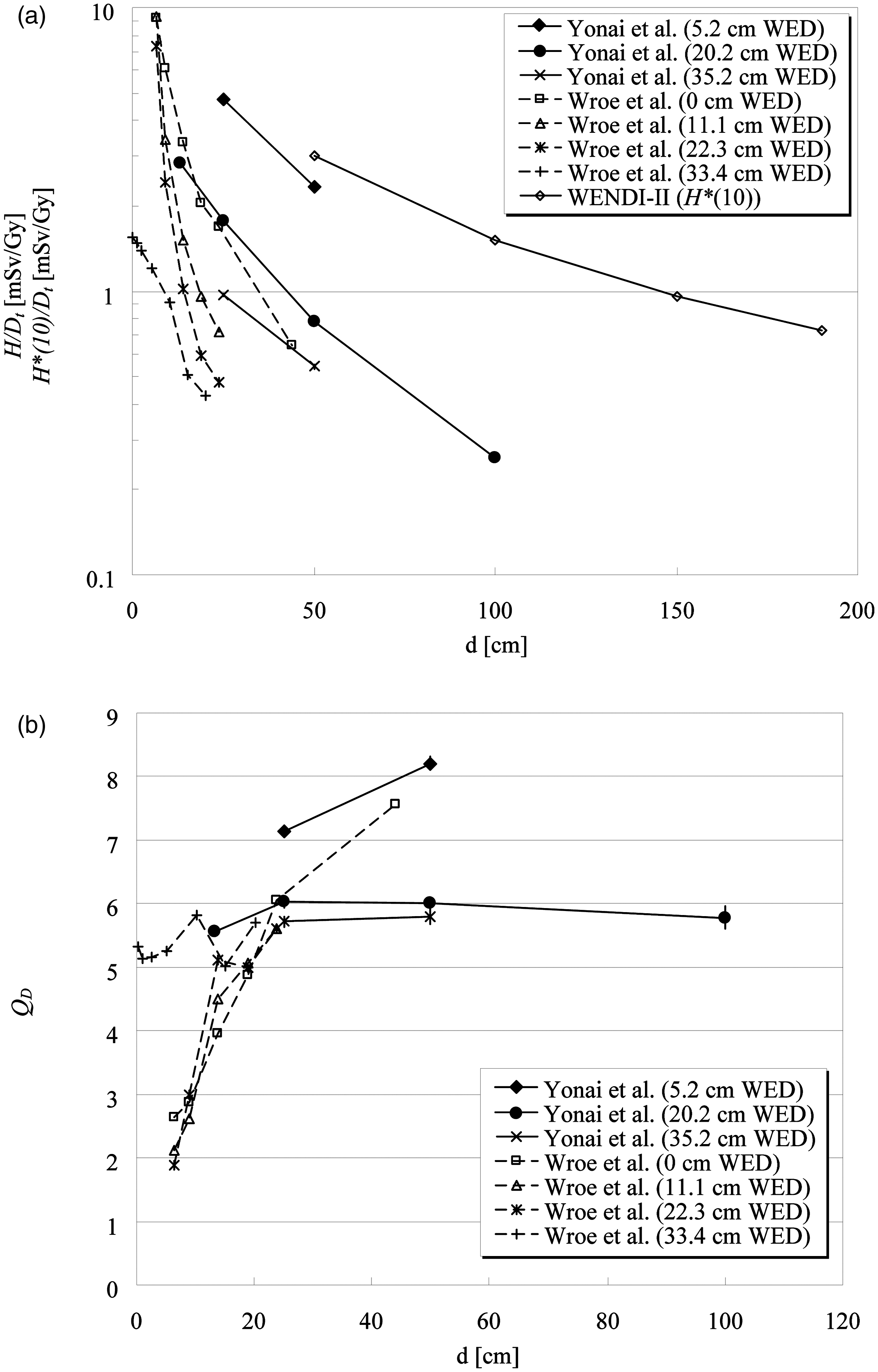
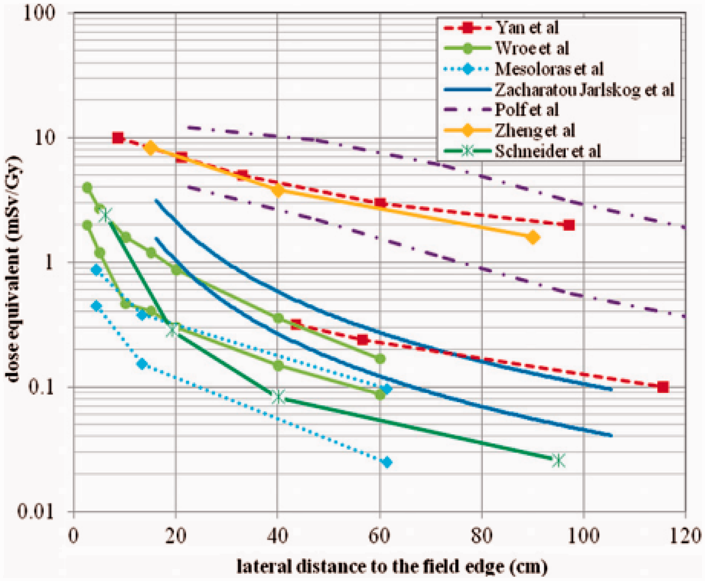
Is out-of-field dose in proton and carbon ion radiotherapy higher than that in external photon beam radiotherapy modalities?
Many studies have been performed to investigate out-of-field exposure of patients receiving external photon beam therapy [e.g. conventional radiotherapy, three-dimensional conformal radiotherapy (3D CRT), IMRT, tomotherapy, and stereotactic radiotherapy] compared with proton and carbon ion radiotherapy. Several review papers have also summarised the dosimetric data (Stovall et al., 1995; Palm and Johansson, 2007; Xu et al., 2008). When considering out-of-field exposure in external-beam photon therapy, the stray photons scattered by the collimator and patient, as well as leakage from the treatment unit heads, are more important than secondary neutrons at relatively low primary photon energies. Above 10 MeV, secondary neutrons produced in photonuclear reactions increase with increasing primary photon energy. Scattered photons dominate near the irradiation field, whereas leakage photons are more isotropic. The neutron dose contribution is relatively independent of distance from the field edge; however, it depends on depth and beam energy. Out-of-field doses in external photon beam radiotherapy also depend strongly on the treatment plan [e.g. field size and total monitor units (MU), accelerator type] due to collimator angle and design including shielding devices (Van der Giessen, 1996; Kry et al., 2005a). Recently, exposure during IMRT was investigated by many groups together with 3D CRT because IMRT and tomotherapy require more MUs to deliver the same prescribed dose to a tumour (Followill et al., 1997; d’Errico et al., 2001; Vanhavere et al., 2004; Howell et al., 2005, 2006; Kry et al., 2005a,b, 2007). Athar et al. (2010) compared proton and 6-MV IMRT treatments for a variety of treatment plans and patient age groups. They concluded that, in-field, there is a distinct advantage for proton beams due to the lower integral dose. Out-of-field but within 20 cm distance, there was an advantage for IMRT, while further away, the neutron equivalent dose from proton radiotherapy was clearly lower than the scattered photon dose in IMRT. Yonai et al. (2010) compared the out-of-field dose in proton and carbon ion radiotherapy using the broad beam method with that in IMRT as obtained by Kry et al. (2007). Assuming treatment doses of 66 Gy(RBE)
b
for a 400-MeV n−1 carbon ion beam and 74 Gy(RBE) for a 235-MeV proton beam, which are the typical conditions for treatment of prostate cancer, the total dose equivalents at 13 cm from the beam axis and 20 cm depth in a water phantom are up to 190 mSv for both beams. Also, the dose equivalent at 25 cm from the beam axis and 5 cm depth in a water phantom is 57 mSv for the carbon ion beam and 192 mSv for the proton beam when assuming two opposed beams. These values are comparable to or less than those of lung, oesophagus, and thyroid in 3D CRT and IMRT for prostate cancer.
5.1.3. Risk assessment of stochastic effects, especially second cancers
The expanding use of radiotherapy, coupled with improvement in long-term patient survival, means that constant vigilance is needed to monitor and evaluate the possible risks of second cancer after radiotherapy (NCRP, 2011). The risk of second cancer depends on the volume of the high-dose region in the irradiation field and the low-dose region outside the field. Proton and carbon ion radiotherapy achieves the best dose distribution for the target volume, as mentioned above, and obviously results in not only reducing side effects in OARs but also minimising the risk of second cancer within or near the irradiation field. The risk of second cancer in the low-dose region (i.e. whole-body exposure) remains a controversial issue. As shown in Section 5.1.2, this exposure is considerably lower than that close to the treatment target volume, but it may not be negligible for risk assessment, especially for younger patients. Fontenot et al. (2009) assessed the risk of second cancer from proton radiotherapy with the broad beam method and 6-MV IMRT, taking into account the contributions from primary and secondary radiations for prostate cancer. Doses from the primary and secondary radiations were determined from treatment planning and Monte Carlo simulation, respectively. The risk was estimated using risk models from the BEIR VII Report (2006). They concluded that proton radiotherapy can reduce the incidence of second cancer in patients with prostate cancer compared with IMRT, even if the dose from secondary neutrons is included. However, the primary beam is the dominant contributor to the risk of second cancer for both modalities, and the impact of the neutrons produced in proton radiotherapy is of secondary importance. Although different methods were used by Schneider et al. (2007) and Fontenot et al. (2009) to calculate the risk, the relative risk estimates for proton radiotherapy with the scanning method agree remarkably well. Newhauser et al. (2009) assessed the absolute lifetime risk of second cancer after receiving craniospinal proton radiotherapy using Monte Carlo simulations, and combined their work with the previous risk assessment for the primary beam by Miralbell et al. (2002). They showed that the risks of second cancer from IMRT and conventional photon treatments were seven and 12 times higher than the risk from proton treatment with the scanning method, respectively, and six and 11 times higher than the risk from the broad beam method, respectively. It was also noted that the risk of proton radiotherapy was dominated by primary proton radiation, not secondary neutrons, which is the same conclusion reached by Fontenot et al. (2009). These studies concluded that the undesired dose in the out-of-field volume is negligible for the risk of second cancer in proton radiotherapy. Zacharatou Jarlskog and Paganetti (2008) estimated the risk caused by neutrons outside the treatment volume and the dependence on the patient’s age based on the BEIR risk models. Their findings were as follows.
The main contributors (>80%) to neutron-induced risk were neutrons generated in the treatment head. A change in treatment target volume causes a variation of the risk by up to a factor of two. Young patients are subject to greater risks than adult patients because of the geometric differences and age dependence of the risk models. Although the organ-specific risks seem to be rather small, the total risk for all organs is not negligible. This is particularly true for very young patients. Athar and Paganetti (2009) used computational whole-body (gender-specific and age dependent) voxel phantoms. They analysed the risk of second cancer for various organs as a function of patient age and field size based on two risk models. For example, breasts, lungs, and rectum had the highest radiation-induced lifetime cancer incidence risks in an 8-year-old female patient treated with a spinal proton radiotherapy field. These were estimated to be 0.71%, 1.05% and 0.60%, respectively. Risks for male and female patients decrease as their age at treatment time increases. Schneider et al. (2008) also investigated the risks for an adult treated for prostate cancer and a 14-month-old child with a rhabdomyosarcoma of the prostate using the organ equivalent dose concept (Schneider et al., 2005). Proton radiotherapy with the broad beam method was added by assuming that the neutron dose was five-fold higher than the dose with the scanning method. They showed that the risk of second cancer in the adult after IMRT or passive proton radiotherapy is not increased by more than 15% compared with conventional radiotherapy. In the child, the risk remains practically constant or is even reduced for proton therapy. They also concluded that:
the cumulative risk in the child can be as much as 10–15 times higher than that in the adult; the ratio of the volume that receives dose lower than 2 Gy relative to the volume that receives dose more than 2 Gy varies between 10 and 20 in the adult and between 7 and 9 in the child, so the impact of scatter and leakage radiation is more pronounced in the child; and IMRT and proton radiotherapy (regardless of the irradiation method) will lower the risk in the child compared with 3D CRT. These results indicate that the reduction of undesired dose in the out-of-field volume through use of the scanning beam method or an additional shielding technique can lower the risk. Each facility should control (manage) the out-of-field dose and make an effort to reduce it. Unfortunately, no publications on risk assessment in carbon ion radiotherapy are available at present. However, undesired dose in normal tissue is at least comparable to that in proton radiotherapy, and consequently, the risk should be similar. Additional questions on higher RBE for the induction of cancers are still to be answered (ICRP, 2003b). Information and data are needed, particularly by treatment centres already using carbon ions in clinical practice. Also, epidemiological studies for the risk of second cancer are required for the treatment centres. The risk assessment includes large uncertainties of dose assessments. Additionally, there are uncertainties on biological effects, the dose–response relationship in the low-dose region, and effects of dose rate and fractionation, etc. as mentioned in Section 4. Monte Carlo simulations must be further verified experimentally; therefore, more experimental information is desired because the available literature is still limited compared with that on photon radiotherapy. In addition, it should be remembered that doses by primary and secondary radiations depend on treatment planning and facility. At present, it is difficult to draw a general conclusion concerning the risk of second cancer after ion beam radiotherapy. However, there is no evidence that the risk of second cancer is higher after ion beam radiotherapy compared with after external photon beam radiotherapy.
5.2. Medical exposure of patients from imaging procedures
Imaging procedures involved in ion beam radiotherapy include x-ray CT for treatment planning, radiographic and fluoroscopic procedures for treatment rehearsal and patient setup verification at the beginning of each dose fraction, and fluoroscopy and respiratory-correlated CT such as time-resolved CT (4DCT) for organ motion tracking during ion beam delivery. Although these imaging procedures provide significant information for ion beam radiotherapy, they also give additional radiation doses to the patient. There have been concerns about total imaging doses in recent years (Murphy et al., 2007). Doses delivered by each imaging procedure have been published widely through the literature. This section provides data to allow medical staff to estimate the total radiation doses
c
delivered to patients from imaging procedures during ion beam radiotherapy and during follow-up after treatment.
5.2.1. Review of dose delivered to patients from imaging procedures
Conventional CT
CT remains the primary method used for radiotherapy treatment planning, as well as being a type of diagnostic imaging. CT procedures deliver relatively high doses compared with other radiography techniques, and it is therefore important to recognise the dose from CT imaging. The principal dosimetric quantities used in CT are the CT dose index (CTDI) and dose length product (DLP). CTDI is defined as the integral along a line parallel to the axis of rotation of the dose profile for a single rotation, divided by the nominal x-ray beam width (ICRP, 2001). CTDI is assessed as the absorbed dose in air using a pencil ionisation chamber with an active length of 100 mm. Reference dosimetry for CT is based on such measurements made within a standard CT dosimetry phantom, which comprises homogeneous cylinders of polymethyl methacrylate with diameters of 16 cm (head) and 32 cm (body). Dose values in these phantoms are expressed as weighted CT dose index (CTDIw) of five reference points in the phantom. As nearly all scanners on the market today are multidetector CT systems with a spiral scan mode, the standard dose paramater today is CTDIw divided by the pitch, expressed as CTDIvol (mGy). DLP represents the overall energy delivered by a given scan protocol, and can be integrated over the scan length. Reference doses in CTDI and DLP from a number of studies are given in Publications 87 and 102 (ICRP, 2001, 2007a). Doses to patients are optimally characterised by absorbed doses to each tissue or organ (organ dose) of the body, although this approach is rather difficult for routine use. One common method for estimating organ doses is based on measurements using small dosimeters, such as thermoluminescence dosimeters (TLDs) and radiophotoluminescence glass dosimeters (RGDs), set in various organ positions within an anthropomorphic phantom representing the patient. Another method is dose calculation using conversion factors derived from Monte Carlo simulation of photon interactions within a computational anthropomorphic phantom. Examples of mean organ doses to adults based on measurements or calculations for various CT examinations, using single-slice CT (SSCT) and multislice CT (MSCT), are shown in Table 5.1 (Nishizawa et al., 1991, 2008a,b; Shrimpton et al., 1991; Fujii et al., 2007; Huang et al., 2009; Mori et al., 2009). Doses delivered to a patient in a given examination will be highly dependent on the characteristics of the CT scanner, the size of the patient, the anatomical region under investigation, and the technical factors used in each examination. Therefore, the doses will vary between institutions and even between different equipment and techniques within an institution. For children, organ doses in CT examinations have been evaluated using a paediatric physical or computational phantom. These dose data have been published in several reports (Zankl et al., 1995; Fujii et al., 2007; Lee et al., 2007; Nishizawa et al., 2008a,b). Zacharatou Jarlskog et al. (2008) reported on the out-of-field doses due to neutron radiation in proton radiotherapy, using the broad beam method, for brain lesions, and compared the doses with the radiation expected from a chest CT scan (Table 5.2). The equivalent doses for thyroid, lung, and stomach from proton radiotherapy are of the same order of magnitude as the doses from multiple CT scans. Fast dynamic CT (often referred to as 4DCT) allows a temporal sequence of 3D images during the breathing cycle. Prior to or during treatment, 4DCT is used to accurately determine the target volume of tumours by minimising image degradation caused by respiratory motion. One method for data acquisition is to perform a continuous helical scan and sort the sonogram data according to physiological signals or time stamps. Another method is to perform 4DCT in the cine mode, where the scanner operates without couch movement and acquires one respiration cycle of CT data at each cough position, before moving to the next position. Keall et al. (2004) have shown that air kerma, free in air, in thoracic 4DCT in continuous helical scan mode with a pitch factor of 0.125 will be in the range of 250–400 mGy. Mori et al. (2009) reported organ doses in 4DCT cine mode (Table 5.1). Mean organ doses in various computed tomography (CT) examinations. SSCT, single-slice CT; MSCT, multislice CT; 4DCT, time-resolved computed tomography. [1] Shrimpton et al. (1991). [2] Nishizawa et al. (1991). [3] Nishizawa et al. (2008b). [4] Nishizawa et al. (2008a). [5] Fujii et al. (2007). [6] Huang et al. (2009). [7] Mori et al. (2009). Equivalent doses for thyroid, lung, and stomach due to neutron radiation calculated in passive scattered proton radiotherapy considering a 70-Gy treatment for brain lesions. CT, computed tomography. The therapeutic dose was modified with a scaling factor of 1.5 to account for fractionation (BEIR-VII, 2006). The values are compared with radiation to be expected from a chest CT scan as a function of patient’s age (Lee et al., 2007). Modified from Zacharatou Jarlskog et al. (2008).
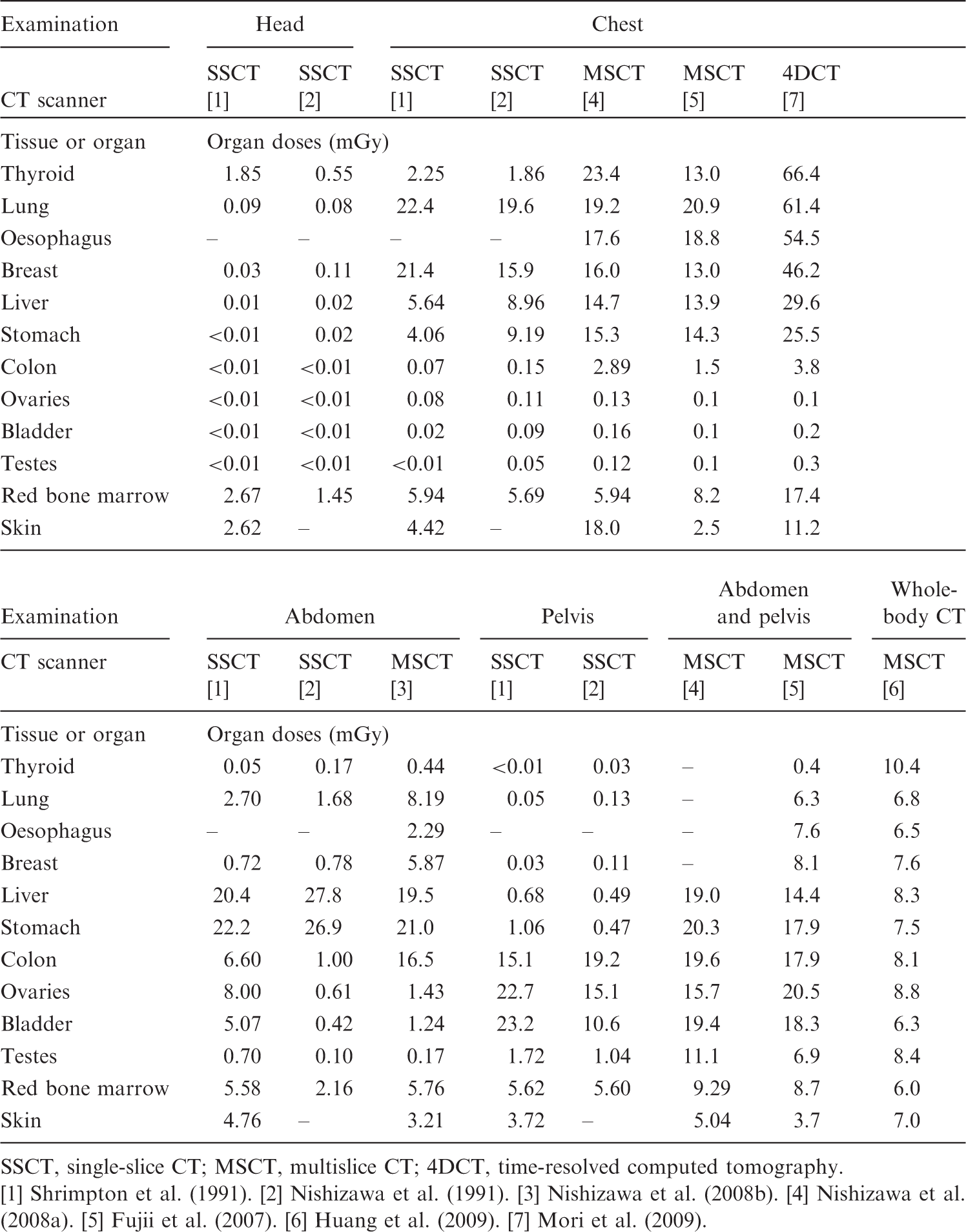
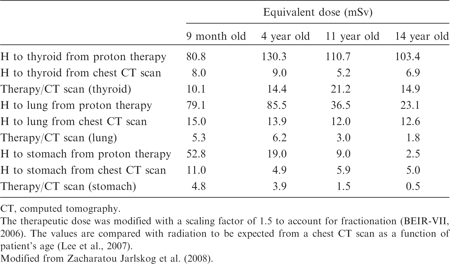
Radiography and fluoroscopy
Radiography is used for the treatment rehearsal and in the daily verification of patient setup at the start of every fraction. Fluoroscopy, with image intensifiers and flat panel detectors, is also used for the treatment rehearsal. These procedures mainly involve taking orthogonal radiographs from anterior–posterior and lateral viewpoints. The dosimetric quantities in radiography and fluoroscopy are expressed in terms of air kerma free in air, entrance surface dose (ESD), and dose–area product (DAP). ESD is defined as the absorbed dose to air at the centre of the beam, including backscattered radiation. DAP is defined as the absorbed dose to air averaged over the area of the x-ray beam in a direction perpendicular to the beam axis, multiplied by the area of the beam in the plane. Hart et al. (2007) reported reference doses in ESD and DAP for common radiographic and fluoroscopic x-ray imaging procedures. Jones and Wall (1985) reported the mean organ doses per unit ESD using Monte Carlo techniques for individual x-ray beam projections in various x-ray examinations. Organ doses in medical x-ray examinations can be estimated using a Monte Carlo programme (PCXMC) developed by STUK, the Radiation and Nuclear Safety Authority of Finland (Tapiovaara and Siiskonen, 2008). Organ doses will vary widely depending on the projection of the x-ray beam, x-ray equipment, and the physical factors used. Organ doses for a given type of examination have large variations, as much as two or three orders of magnitude, between institutions. Hart et al. (2007) reported that ESDs in a chest radiograph for children should be much smaller than those for adults as lower doses for children would be sufficient to produce a satisfactory image. Fluoroscopy commonly takes from 30 s to 1 min for a treatment simulation. Fluoroscopy is also required for respiratory motion management techniques including beam gating and dynamic tracking. Typical fluoroscopic units with an image intensifier will automatically adjust fluoroscopic technical parameters, such as the tube potential and tube current, to obtain acceptable images. Thus, the dose levels will vary widely between examinations because the automatic settings will differ from site to site and according to the patient’s weight. Murphy et al. (2007) reported that the typical ESD to a patient would be approximately 20 mGy min−1 for pre-treatment fluoroscopic procedures.
Cone beam CT
CBCT is used for treatment planning and verification of the target volume, although it is subject to cupping artefacts and inaccuracies in the Hounsfield number. There have been studies on dose levels from CBCT for different scan sites. Islam et al. (2006) reported doses evaluated using 30- and 16-cm-diameter cylindrical water phantoms. For a tube voltage of 120 kVp, 330 projections at 2 mAs per projection, and a source/detector distance of 154 cm, the typical doses to the phantom at the centre of and on the surface of the body phantom were 16 mGy and 23 mGy, respectively. For the head phantom, the centre and surface doses were 30 and 29 mGy, respectively. Some authors have reported organ doses evaluated with an adult anthropomorphic phantom (Endo et al., 1999; Kan et al., 2008: Sawyer et al., 2009). Typical technical parameters and organ doses in CBCT are summarised in Table 5.3. The organ doses in CBCT examinations can be two or three times higher than in x-ray CT. Thus, CBCT will deliver a substantial amount of dose to the critical organ near the target volume. Kan et al. (2008) indicated that there was no significant difference in the matching accuracy of planning between the use of standard and lower mode CBCT images, and hence it is possible to reduce the radiation doses using conventional x-ray CT alone. Mean organ doses in various cone beam computed tomography (CBCT) examinations.
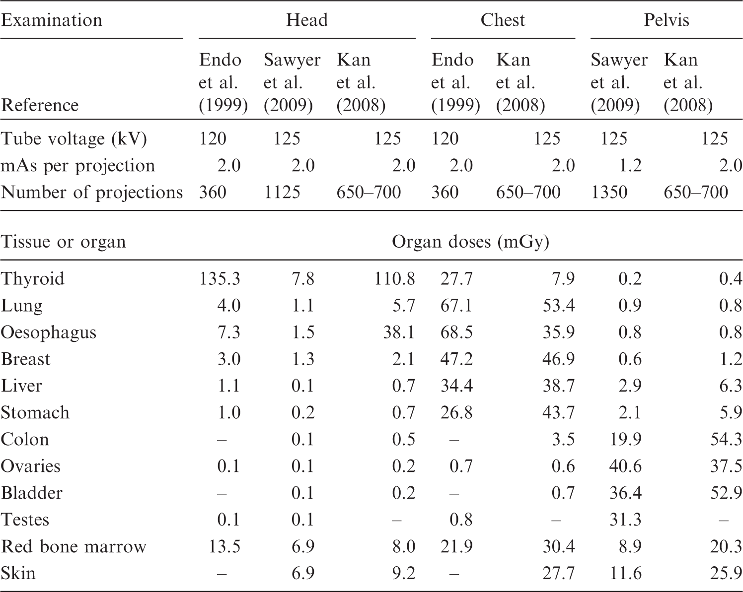
Nuclear medicine procedures
Nuclear medicine procedures, such as planar imaging using a γ camera, single photon emission CT, PET, and/or PET-CT, are performed as one type of diagnostic imaging method before ion beam radiotherapy and for follow-up after treatment. Internal dose estimations in the patients after nuclear medicine procedures are required for radiological protection, and one method for estimating organ dose for a reference patient from the administration of various radiopharmaceuticals is to use organ dose coefficients given in Publications 53, 80, and 106 (ICRP, 1987, 1998b, 2008). These dose coefficients are estimated based on biokinetic models and estimates of the biokinetic data for individual radiopharmaceuticals, and are given for adults and children of 1, 5, 10, and 15 years of age. The mean absorbed doses to tissues and organs are given as mGy per unit activity administered (MBq), and can be estimated by multiplying the dose coefficients for individual radiopharmaceuticals by the activity of the administered radiopharmaceuticals.
5.2.2. Total imaging doses for ion beam radiotherapy
This section describes the total imaging dose delivered to patients from various imaging procedures in ion beam radiotherapy. The following shows an example of the dose from each imaging procedure in carbon ion radiotherapy at HIMAC. For an adult patient with prostate cancer, the organ doses from imaging procedures required for carbon ion radiotherapy are considered as follows. Doses to the colon are important because of its high radiosensitivity. Typical imaging procedures and colon doses in each procedure involved in carbon ion radiotherapy for prostate cancer at HIMAC are summarised in Fig. 5.8. In Procedure 1 (diagnostic examination before treatment), when a patient undergoes a diagnostic pelvic CT scan, colon doses from Table 5.1 can be estimated to be approximately 15–20 mGy. In Procedure 2 (treatment planning), when the patient undergoes a single x-ray CT procedure, colon doses are approximately 15–20 mGy. In Procedure 3 (treatment rehearsal), the patient undergoes orthogonal x-ray radiographic procedures, and colon doses in an orthogonal radiograph were estimated using a Monte Carlo programme (PCXMC) to be approximately 0.4–0.5 mGy. When the patient undergoes radiographic procedures, the total colon doses can be estimated to be 3–4 mGy. In Procedure 4, the patient undergoes the radiographic procedures for the daily patient setup verification at the start of each fraction. Given 16 fractions per 4 weeks of treatment for prostate cancer and four orthogonal radiographs per fraction, colon doses in a total of 64 orthogonal radiographs can be estimated to be approximately 25–35 mGy. Finally, in Procedure 5 (follow-up after treatment), when the patient undergoes a diagnostic pelvic CT scan, the colon doses can be approximately 15–20 mGy. Thus, typical total colon doses delivered from various imaging procedures during and after ion beam radiotherapy would reach approximately 100 mGy. This value can vary proportionally to the treatment fractions and frequency of x-ray imaging adopted at an ion beam radiotherapy facility. An example of imaging procedures and colon doses in each procedure associated with carbon ion radiotherapy for prostate cancer at the Heavy Ion Medical Accelerator in Chiba. CT, computed tomography.
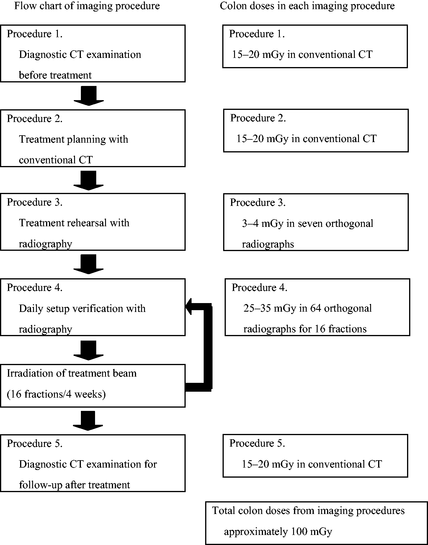
5.2.3. Exposure of comforters and carers
High-energy ion beams, such as protons or carbon ions, induce nuclear reactions in a patient’s body, resulting in the activation of nuclei. This requires the assessment of radiation exposures of people who stay close to the patient after ion beam radiotherapy, such as working staff, comforters, carers, and family members. Tsujii et al. (2009) reported the results of an irradiation experiment with ion beam therapy with soft tissue substitute materials. For evaluation of the exposure of the patient’s family members, the following scenario was assumed: the patient leaves the treatment room 2 min after the end of irradiation and a member of his/her family attends him/her for 2 h. The ion beam radiotherapy for a patient would be carried out for a maximum of 20–30 fractions of irradiation. In the case of carbon ion treatment of 30 fractions, the exposure of the family member was calculated to be 23.5 μGy for HIMAC and 20.8 μGy for HIBMC. The exposure was calculated to be approximately 130 μGy in the case of proton treatment of 30 fractions at HIBMC. The doses from activation in proton radiotherapy were higher than those for carbon ion radiotherapy, partly because proton radiotherapy requires the delivery of more particle fluence to the patient than carbon ion radiotherapy. Most radioactive nuclides produced by ion beam radiotherapy have very short physical half-lives. Even if the family member attends the patient for more than 2 h, the additional increase in exposure is negligible. Therefore, Tsujii et al. (2009) concluded that the exposure of a patient’s family member is substantially lower than 1 mSv year−1.
5.3. Occupational exposure
During ion beam radiotherapy, interactions occur with atomic nuclei in the air of the treatment room, the patient’s body, and beam line devices, and the beams activate the materials depending on the ion species, energy, and irradiation area. The sources for the occupational exposures of radiation workers in the facilities are not the therapeutic beams themselves, but the activated materials related to radiotherapy. The activity is highest just after irradiation of the patient, as the physical half-lives of the induced radioactivity are relatively short, and the radioactivity decreases steadily according to the half-lives of the radionuclides. In ion beam radiotherapy facilities, there are many medical radiation workers including physicians, radiological technologists,
d
medical physicists, nurses, and operators. According to their roles in radiotherapy, some of them will enter the treatment room for preparation tasks before irradiation, take the patient into the treatment room, set the patient position and irradiation equipment, and take the patient outside the room after irradiation. After irradiation, a patient compensator and a patient collimator are moved into the depository. In addition to the medical staff, personnel of the manufacturers and suppliers related to radiotherapy have the opportunity to be inside the facility for maintenance of the beam delivery system and equipment when radiotherapy is not being carried out, and would possibly be exposed to residual radionuclides. Occupational exposures of workers in radiotherapy facilities depend on the induced radioactivity levels in the beam delivery system and equipment, and the position of and time spent by the medical staff and maintenance personnel in the treatment room regarding their contact with, or distance from, the activated materials. The shielding abilities of the irradiation system and rooms are also important factors affecting radiological protection for the workers. Among medical radiation workers, radiological technologists receive the highest level of occupational exposures from the induced radioactivity because of their roles. Based on actual measurements and calculations of induced radioactivity in the specific radiotherapy, the doses to these medical workers can be estimated for assuring adequate radiological protection. In fact, many studies have reported dose estimations by both measurements and calculations in radiotherapy, and significant information has been acquired. For radiotherapy with linear accelerators, Almen et al. (1991) measured the absorbed doses to the trunk and hands of 24 radiological technologists working with accelerators for radiotherapy using TLDs, and estimated that the annual absorbed dose was 2 mGy, primarily caused by radiation penetrating the walls of the treatment room; induced activity in the accelerator contributed one-third to the dose. The absorbed dose to the trunk varied from 1.0 to 2.8 mGy, and the range for the hands was between 0.7 and 3.3 mGy year−1. Of the induced activities in metals in the accelerator, 28Al (physical half-life 2.3 min) and 62Cu (9.7 min) dominated immediately after treatment, and 187W (24 h) and 57Ni (36 h) dominated at a later stage. Fischer et al. (2008) reported comparisons of activation products and induced dose rates at the isocentre of four high-energy medical linear accelerators. They analysed the γ spectra and calculated dose rates. There were 21 radionuclides with physical half-lives between 2.3 min and 5.3 years. Among these induced radionuclides, 28Al, 62Cu, 56Mn, 64Cu, 187W, 57Ni, 196Au, 54Mn, 60Co, and 124Sb were considered to be important for calculating the induced dose rate at the isocentre. The estimated annual doses to radiological technologists were between 0.62 and 2.53 mSv year−1. Perin et al. (2003) derived a model to calculate induced dose rate around an 18 MV ELEKTA linear accelerator. The modelled induced dose rates agreed with measured dose. The maximum annual whole-body dose was estimated to be 2.5 mSv for 60,000 MU week−1. To investigate neutron shielding for a proton radiotherapy facility at the University of Pennsylvania, Avery et al. (2008) calculated the spectra of neutrons produced by 100-, 175-, and 250-MeV proton beams using the Geant4 Monte Carlo simulation code, and estimated dose equivalent rates at various points in the facility based on the calculated spectra data. The annual dose equivalents at various points around the shielding were between 0.02 and 1.19 mSv, and the results showed that the shielding would be adequate for both the public and radiation workers. Newhauser et al. (2005) developed a neutron radiation area monitoring system for proton radiotherapy facilities consisting of measurement equipment, a computer, and software. The system can record and display neutron dose equivalents. Exposures to the maintenance staff from residual radionuclides after synchrotron shutdown at the Loma Linda University Proton Treatment Facility were estimated based on dose measurement around the accelerator and review of the personnel dosimetry records by Moyers and Lesyna (2009). At 300 mm from the surface of the accelerator, all average exposure rates were below 1.7 × 10⁻² mSv h−1. The average annual dose equivalents for seven maintenance personnel bodies were 2.0 × 10⁻² to 2.1 × 10⁻¹ mSv in 2006. For carbon ion radiotherapy, Yashima et al. (2002, 2003, 2004a,b) performed experiments with 230 and 100 MeV n−1 argon, carbon, neon, helium, and phosphorus ions, and obtained radioactive spallation products in a thick copper target at the HIMAC facility (in practice, 400 MeV n−1 ions are also used for radiotherapy). They found agreement with other experimental data and the energy dependence of the reaction yields. They also calculated the spatial distribution of residual radioactivities in copper by the PHITS code, and found that the results calculated using PHITS were in good agreement with the measurements. As evidence to consider proper radiological protection in ion beam radiotherapy, Tsujii et al. (2009) collected information from representative worldwide facilities for ion beam radiotherapy concerning the practical radiological protection at each facility. These therapy facilities are controlled by the same government regulations as ordinary accelerator facilities. Activation levels of the beam line devices and patients were actually measured in two carbon ion radiotherapy facilities and four proton radiotherapy facilities in Japan that use the broad beam method. The practical maximum doses to radiological technologists were assessed based on the measurement data of induced radioactivity. The dose equivalents to the radiological technologist were estimated for the sequential process of detaching a patient immobilisation device, patient collimator, and patient compensator (putting it on a side table), and storing the patient collimator and the patient compensator (moving it to a depository), with the assumption that the radiological technologist repeats this sequence 20 times per day and 260 days per year, as seen in Table 5.4. Tsujii et al. (2009) estimated that, for example, annual effective doses of 290 MeV n−1 and 400 MeV n−1 carbon ion radiotherapy at HIMAC were 1.06 mSv and 0.67 mSv, respectively, and that the annual skin equivalent doses were 9.7 and 4.1 mSv, respectively, as seen in Table 5.5. At HIBMC, the annual effective dose for carbon ion radiotherapy was estimated to be 0.53 mSv and the annual skin equivalent dose was 5.4 mSv under the same conditions and assumptions as those at HIMAC. At three proton radiotherapy facilities, annual effective doses were estimated to be 2.3–5.5 mSv and annual skin equivalent doses were 31–73 mSv, as seen in Table 5.6. The activation doses for proton radiotherapy were higher than those for carbon ion radiotherapy because the fluences of protons to the patients were generally higher than those of carbon ions. Activation doses can be lower using the pencil beam scanning method than the broad beam method for both protons and carbon ions. Table 5.7 summarises estimated annual doses for medical workers. The Commission recommended the dose limits for occupational and public exposures in Publications 60 and 103 (ICRP, 1991, 2007b). For occupational exposures, the dose limit in 5 years is 100 mSv (mean dose 20 mSv year−1), and the maximum dose limit per year is 50 mSv. On the other hand, the dose limit for the public is 1 mSv year−1. By comparing estimated doses of radiological technologists mentioned above with these dose limits of occupational exposure, Tsujii et al. (2009) concluded that the current regulations for photon radiotherapy are also applicable to ion beam radiotherapy. The same radiological protection methods of general linear accelerator radiotherapy can be applied for the protection of occupational exposures based on the data. For occupational exposure in planned exposure situations, the Commission recommended an equivalent dose limit for the lens of the eye of 20 mSv year−1, averaged over defined periods of 5 years, with no single year exceeding 50 mSv (ICRP, 2012). In general, of all organs, the skin could receive the highest dose in x-ray examinations. In addition, the distance between the x-ray entrance surface of the patient and the lens of the eye of the practitioner could not be so close, and hence the dose to the lens would not exceed the new dose limit recommended by the Commission when ordinary radiological protection is performed for radiation workers. Activities, required times, and distances from the radiation source for a radiation technologist working in a carbon ion radiotherapy facility. MLC, multileaf collimator. Evaluation of effective dose uses the dose rate by γ rays, and evaluation of the equivalent dose to the skin uses the total dose rate by β and γ rays (Tsujii et al., 2009). A, detaching the patient fastening device; B, detaching the patient collimator (putting it on a side table); C, detaching the amends filter (putting it on a side table); D, storing the amends filter (moving it to a depository); E, storing the patient collimator (moving it to a depository). Due to the long distance, the dose contribution was ignored. Evaluation of effective dose and equivalent dose of skin for a radiation technologist working in a carbon ion radiotherapy facility (Tsujii et al., 2009). HIMAC, Heavy Ion Medical Accelerator in Chiba; HIBMC, Hyogo Ion Beam Medical Center. 290 MeV n−1 carbon ion irradiation of approximately 150-mm underwater range. 400 MeV n−1 carbon ion irradiation of approximately 250-mm underwater range. Evaluation of effective dose and equivalent dose of skin for a radiation technologist working in a proton ion radiotherapy facility (Tsujii et al., 2009). HIBMC, Hyogo Ion Beam Medical Center; PMRC, Proton Medical Research Center at Tsukuba University; SCC, Shizuoka Cancer Center. A, detaching the patient fastening device; B, detaching the patient collimator (putting it on a side table); C, detaching the amends filter (putting it on a side table); D, storing the amends filter (moving it to a depository); E, storing the patient collimator (moving it to a depository). Summary of estimated annual doses for medical workers (Tsujii et al., 2009).
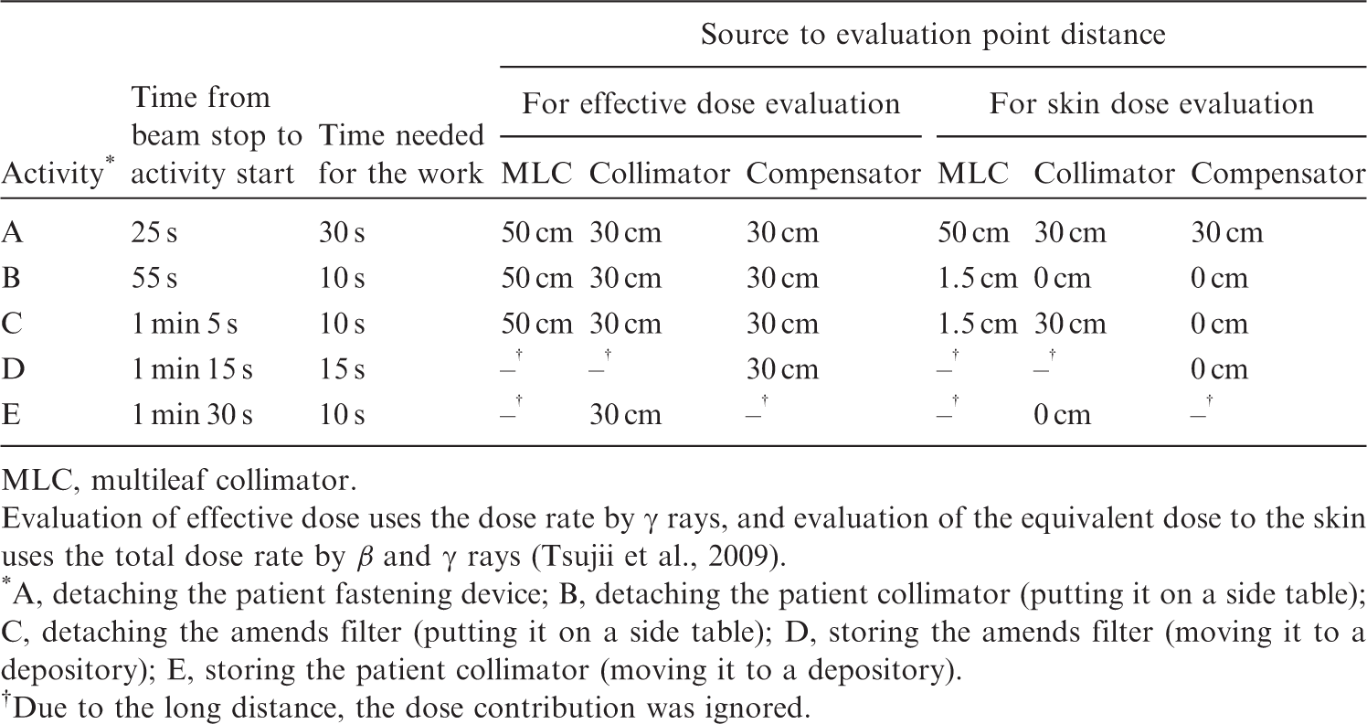
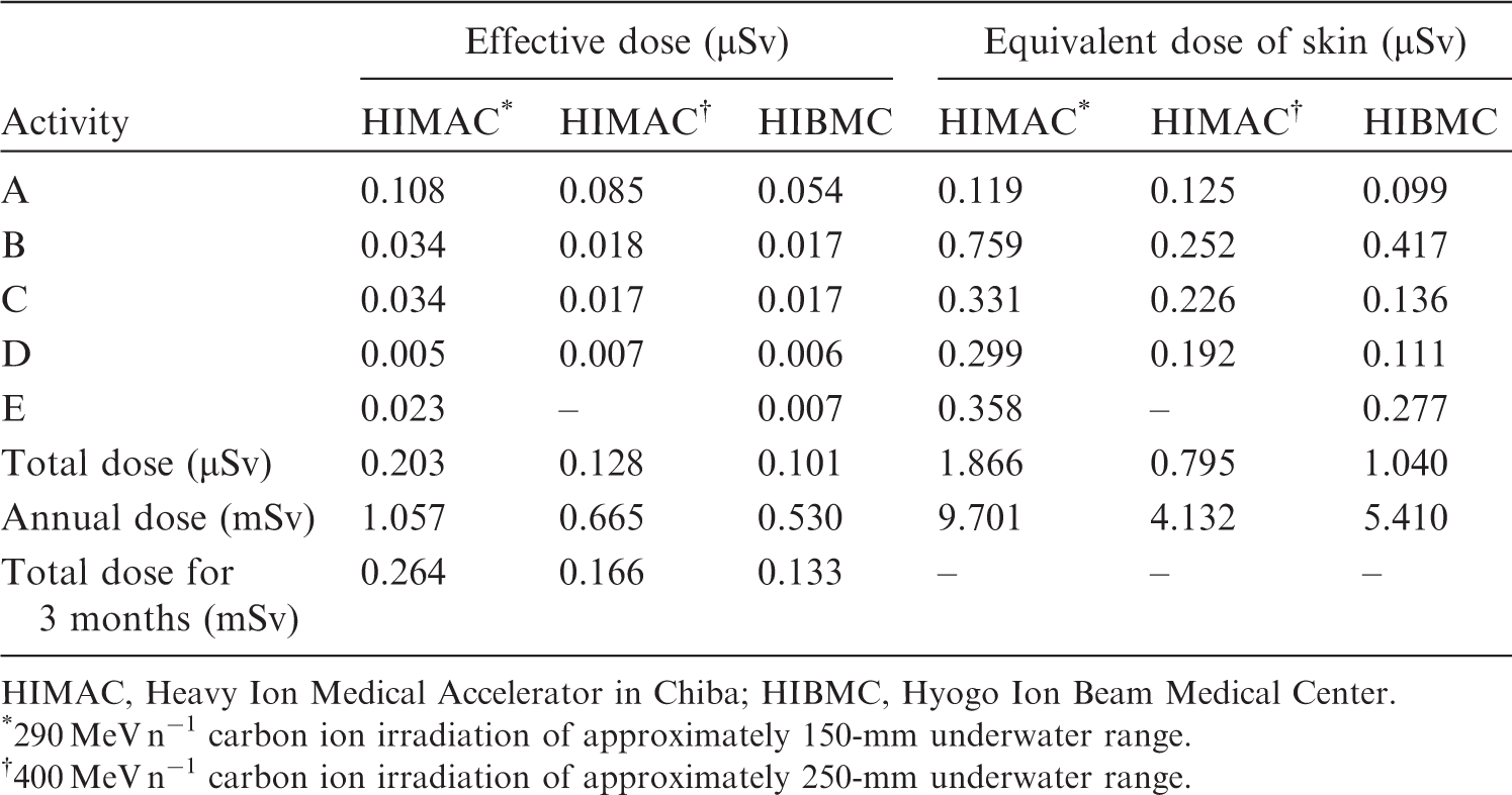
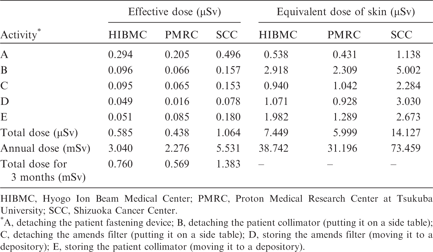
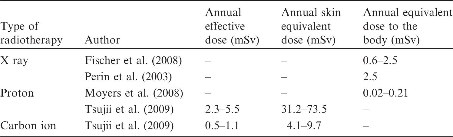
5.4. Public exposure
The sources of public exposures in radiotherapy are different from those of occupational exposures. The major radioactive sources are not the radioactivity produced in the therapy-related devices, but those in the patient. The public can be exposed by coming into contact with patients undergoing radiotherapy. The sources of exposure can also include radioactivity in the exhausted air and wastewater from treatment facilities to the environment. However, the activation levels of sources on public exposures are lower than on occupational exposures because of the physical half-lives of radioactivity and the type of exposure. Tsujii et al. (2009) calculated air activations by protons, fast neutrons, and thermal neutrons at the National Cancer Center Hospital East from consideration of the sources of occupational and public exposures, including effects on the environment, radioactive concentrations of treatment room air and exhaust from facilities, and wastewater. The levels of activation were lower than the Japanese regulatory levels which are based on ICRP recommendations. Transferred from the patient to wastewater through urine, concentration levels were estimated using Monte Carlo simulations, and the influence to the environment was found to be negligible. These data suggest that doses are significantly lower than the public dose limit because of limited contact with the induced radioactivity, and that methods of radiological protection from public exposures in photon radiotherapy facilities are adequate in ion beam radiotherapy facilities.
6. RADIATION SAFETY MANAGEMENT FOR ION BEAM RADIOTHERAPY FACILITIES
6.1. Radiation safety management for ion beam radiotherapy facilities
In countries where ion beam radiotherapy is already practised, a national regulatory framework is in place for radiation sources including medical linear accelerators, and radiation safety standards for experimental high-energy particle accelerator facilities are applied. At an international level, recommendations to national authorities on approaches for defining the scope of radiological protection control measures are given in Publication 104 (ICRP, 2007c). Requirements on national authorities and users of radiation sources are given in the International Safety Standards for Protection against Ionizing Radiation and for the Safety of Radiation Sources (IAEA, 1996). These safety standards include not only requirements for the optimisation of radiological protection, but also requirements for the prevention of accidental exposure in emergency situations, such as switch off, interlocks, and warning signals. Advice on how international safety requirements can be met in radiotherapy is given in IAEA (2006). Lessons from accidental exposures in radiotherapy are provided in Publications 86 and 112 (ICRP, 2000, 2009) and IAEA (2000). However, in addition to general issues for safety and security that need to be addressed, specific issues associated with high-energy ion beams, such as exposures due to activation of the irradiation equipment, should be addressed by the management of the facilities. This section provides advice on specific radiation safety management that is required to ensure optimisation in these facilities, and compliance with the dose limits for occupational and public exposures. Measures to prevent accidental exposure are given in Section 7.
6.2. Management of exposure due to activation of devices
Specific issues for relevant safety management in ion beam radiotherapy facilities are associated with exposures from activated equipment and patients that are directly irradiated by high-energy ion beams. The devices of concern are those directly exposed to the treatment beams, especially if they are placed near patients or handled manually by radiological technologists: these include patient immobilisation devices, collimators, patient compensators, ridge filters, range shifters, and dosimetric instruments. The levels of dose received from handling these devices are shown in Tables 5.6 and 5.7. These levels are well below the relevant dose limits.
6.3. Management of radioactivity due to activated nuclides
6.3.1. Air activity concentration in the treatment room
Occupational exposure from air activated during beam acceleration and transport should be evaluated. Activity concentration in air of a treatment room has been estimated (Tsujii et al., 2009). Radioactivity in air A1i (Bq) of a nuclide induced by ion beams can be calculated by the following equation:
Radionuclides that may be produced by air activation, and their attributes, are listed in Table 6.1 (Tsujii et al., 2009). In ion beam radiotherapy facilities, air activation by secondary neutrons should be considered as well as that by the main beam. Radioactivity in air A2i (Bq) of a nuclide induced by secondary fast neutrons can be calculated by the following equation:
Radioactivity in air A3i (Bq) of a nuclide i induced by secondary thermal neutrons can be calculated by the following equation:
Activity concentration of nuclide i in the air of the treatment room CR (Bq cm−3) averaged over time T (s) can be calculated by:
Nuclides which may be produced by air activation (Tsujii et al., 2009).
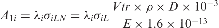
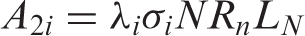
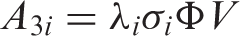
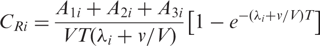
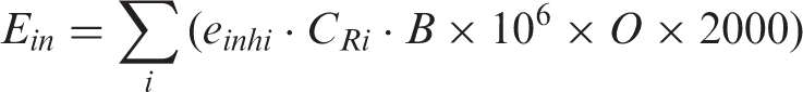
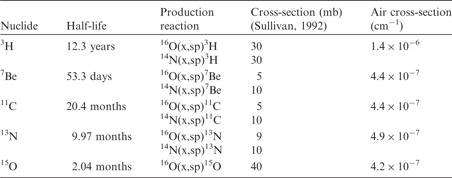
6.3.2. Discharge of air from the radiotherapy facilities
In addition to estimating the radioactivity concentration in air activated in the treatment room, shown in Section 6.3.1, the concentration of air discharge should also be estimated in the design stage of the facility to confirm compliance with the authorised discharge limit given by a regulatory body to evaluate dose to the public living in the surrounding area. The concentration should also be monitored by an appropriate measurement system in the operational stage when the radioactive concentration in air is estimated to be beyond the maximum concentration level given by the regulatory agency. Activity concentration of nuclide i in exhaust from a facility (Cx) averaged over time T(s) can be calculated by:
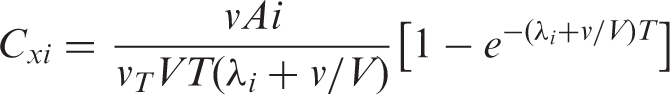
6.3.3. Management of solid waste
When devices, or component parts, that have been activated with a radiotherapy beam are replaced, consideration to avoid unnecessary exposure is required. If they are put into temporary storage, this storage may be in or out of a controlled area depending on the concentration of radioactivity. If a clearance system has been introduced or will be introduced, the activated materials should be treated as a candidate for clearance to re-use or recycle in the case that the activity concentration is lower than the clearance level criteria. The clearance level is established by national regulatory authorities by reference to levels proposed in the IAEA Safety Guide (IAEA, 2004).
6.3.4. Release of patients and management of their excreta
The time required for the release of a patient who has received ion beam radiotherapy, and the need to manage their excreta, should be considered in relation to the exposure of any member of the patient’s household. As shown in Section 5.2.3, the dose to the comforters and carers was found to be far below 1 mSv per episode, and no specific protection procedures are required (ICRP, 2007b).
6.4. Monitoring system for management of radiological protection
A monitoring system should be established in facilities to ensure radiological protection in public exposure, occupational exposure, and medical exposure of patients. The system should include supplying an appropriate monitoring device for the evaluation of these exposures, including both external and internal exposures. External dose of γ rays and neutrons should be monitored by area monitors or survey monitors. Activity concentrations of the nuclides can be monitored with appropriate gas monitor and dust monitor equipment in the treatment room. If the concentration is not monitored, it should be assessed by calculation.
6.5. Quality assurance in management of radiological protection of ion beam radiotherapy facilities
A quality assurance (QA) programme for management of radiological protection should be established. The programme should cover the following items: (i) maintenance of records of relevant procedures and results; (ii) measurements of the physical parameters of the irradiation instrument, the apparatus for shielding, and the devices for beam forming and measuring instruments; (iii) verification of the appropriate calibration and conditions of dosimetry and monitoring instruments; and (iv) continuous quality improvement.
7. PREVENTING ACCIDENTAL EXPOSURES OF PATIENTS FROM ION BEAM RADIOTHERAPY
New technologies in radiotherapy brought highly conformal dose distribution, such as dose escalation in the target volume without increasing the radiation dose to neighbouring healthy tissues. However, even subtle errors during the treatment process could easily have severe consequences. In order to avoid such accidental exposures, there is a need for prospective, structured, and systematic approaches to the identification of system weaknesses and the anticipation of failure modes (ICRP, 2009).
7.1. Accidental exposures to patients undergoing radiotherapy
Typical accidental exposures where the radiation administered is not given as intended can be classified as follows: a patient receives the treatment planned for a different patient; the patient is correct, but the wrong part of the body (e.g. wrong site or wrong side) is irradiated; the patient and the part of the body are correct, but an unplanned volume is irradiated; and the patient, site, and volume are correct, but the wrong dose is given. Disseminating the knowledge and lessons learned from accidental exposures is crucial in preventing re-occurrence. This is particularly important in radiotherapy; the only application of radiation in which very high radiation doses are deliberately given to patients to achieve cure or palliation of disease (ICRP, 2009). Ion beam radiotherapy can be categorised as external-beam radiotherapy. As shown in Section 2.2.4, the procedure consists of patient immobilisation, planning CT, treatment planning, patient positioning, and beam delivery in the same way as external-beam radiotherapy. Lessons from accidental exposures in conventional external-beam radiotherapy are applicable to prevent those from ion beam radiotherapy. Retrospective compilations of lessons learned from the review and analysis of accidental exposures in radiotherapy have been published (IAEA, 2000; ICRP, 2000, 2009; WHO, 2008). These are useful to check whether a given ion beam radiotherapy facility has sufficient provision in place to avoid accidental exposures similar to those reported. As an example, major accidental exposures caused by errors in the calibration and commissioning of radiotherapeutic equipment have led to putting preventive measures in place, such as an independent redundant determination of the absorbed dose to detect possible beam calibration errors.
The first two types of events may also happen in general medical practices other than radiotherapy, and should be discussed in terms of general patient safety. On the other hand, the latter two types of events can be attributed more specifically to radiotherapy, and this is described briefly in this section.
7.2. Potential accidental exposures in ion beam radiotherapy
As described in Chapter 2, one of the features of ion beam radiotherapy is dose localisation characterised by the Bragg peak, sharp distal falloff, and lateral penumbra. It enables one to focus dose distribution on the target volume (e.g. malignant tumour) adjacent to the OAR, where the dose should be as low as possible. There are potential advantages to patients from ion beam radiotherapy, but substantial concerns persist as uncertainties in beam parameters and target position are more critical in ion beam radiotherapy. The TPS customised to ion beam radiotherapy can design precise collimators and range compensators to spare OARs. The TPS also generates various beam parameters for an accelerator, and possibly large datasets for scanning magnets and fluence distribution in the case of scan irradiation. It should be noticed that these functions of the TPS are specific to ion beam radiotherapy and are not necessarily directly related to lessons in conventional external-beam radiotherapy. Thus, in addition to events that can occur in any radiotherapy practice, it is necessary to identify initiating events that are specific to the systems and procedures employed in ion beam radiotherapy facilities. As lessons from published events with these systems and procedures are not yet available, retrospective approaches are not sufficient in ion beam radiotherapy, and prospective approaches to identify potential risks should be considered carefully for a comprehensive QA programme. Cantone et al. (2013) recently reported an example of a prospective approach in proton radiotherapy. Table 7.1 shows an example of risk assessment specific to ion beam radiotherapy, with possible initiating events associated with each task of the radiotherapy process, together with the potential consequences of each initiating event and its preventive measures. A simplified example of safety assessment for ion beam radiotherapy. CT, computed tomography; WEL, water equivalent length; OAR, organ at risk; TPS, treatment planning system; SOBP, spread-out Bragg peak; MU, monitor unit. This list of events is not exhaustive, but is intended as a sample to show how the assessment can be performed. The listed events are specific to ion beam radiotherapy, and therefore, other events of general nature that are also applicable to photon or electron beam radiotherapy are not listed here.

7.3. Quality assurance programme and audit
A comprehensive QA programme can lead to the detection of systematic errors, and decrease the frequency and severity of random errors (ICRP, 2000). Although no comprehensive QA programme specific to ion beam radiotherapy has been published, some professional bodies prepared documents regarding QA for ion beam radiotherapy: a QA guideline (JSMP, 2005) is being updated, an international safety standard was developed (IEC, 2014), and ICRU prepared a code of practice for ion beam radiotherapy (ICRU, 2007). These are expected to be useful to establish a comprehensive QA programme at an ion beam radiotherapy facility. Independent external audits are a necessary part of a comprehensive QA programme in radiotherapy (IAEA, 2007). The ultimate purpose of a QA audit is to assess the current situation and to improve the quality of the radiotherapy process at the reviewed institution or programme. A comprehensive audit of a radiotherapy programme reviews and evaluates the quality of all the elements involved in radiation therapy, including staff, equipment and procedures, patient protection and safety, and overall performance of the radiotherapy facility, as well as its interaction with external service providers. Possible gaps in technology, human resources, and procedures will be identified so that the institutions affected will be able to document areas for improvement. Although such a comprehensive audit has not yet been established for ion beam radiotherapy, some audit activities are being undertaken. In the USA, any proton radiotherapy facility participating in a National Cancer Institute (NCI)-supported clinical trial is required to accept an on-site dosimetry audit coordinated by the Radiological Physics Center (RPC; amended to “Imaging and Radiation Oncology Core (IROC)” in 2014), based on the Guidelines for the Use of Proton Radiation Therapy in NCI-Sponsored Cooperative Group Clinical Trials (RPC, 2012; Moyers et al., 2014). In Japan, dosimetry intercomparisons were performed by the National Institute of Radiological Sciences (Fukumura et al., 1998, 2008), and a multi-institutional group discussed the guidelines of a comprehensive QA programme and performed dosimetry intercomparison for ion beam radiotherapy (Ozawa et al., 2013). All ion beam radiotherapy facilities are recommended to participate regularly in an external audit programme to verify the calibration of treatment units, ideally each year, but at least every 5 years. It has been reported that fewer and smaller discrepancies in beam calibration occur at facilities that have participated regularly in external audits compared with facilities that have not participated in such programmes (ICRP, 2000). As ion beam radiotherapy requires a large accelerator and more complex systems than conventional radiotherapy, time dedication, training, and competence of the staff need to be re-assessed. Once these issues have been addressed properly, a smooth, step-by-step, and safe transition over several years is necessary to maintain safety. It should be noted that failure to do so may not only be a waste of resources but may also increase the likelihood of accidental exposure of patients.
8. CONCLUSIONS AND RECOMMENDATIONS
Ion beams, such as protons or carbon ions, in radiotherapy provide excellent dose distribution to the targeted tumour tissue, primarily due to their finite range, allowing significant reduction of the undesired exposure of normal tissue outside the target tumour. The first step for ion beam radiotherapy, similar to any medical procedure, is justification. The proper selection of the patient should be based on knowledge of radiation oncology, the specific tumour to be treated, and available clinical results to provide optimal benefit to the patient. Careful treatment planning is required for optimisation to maximise the efficiency of treatment and to minimise the dose to normal tissue. This depends on the specific treatment method and the specific targeted tumour. Theoretically, in comparison with conventional radiotherapy, ion beam radiotherapy delivers radiation dose to the target volume in a more efficient manner, while reducing undesired exposure of normal tissue. Nonetheless, the treatment planning must be sufficiently precise to avoid damaging critical organs or tissues within or near the target volume. An ion beam delivery system consists of an accelerator, a high-energy beam transporter, and an irradiation system. When ion beams pass through or hit these beam line structures, secondary neutrons and photons can be produced, as well as particle fragments and photons from the activated materials. Doses in the out-of-field volumes arise from secondary neutrons and photons, particle fragments, and photons from activated materials. These doses should be considered from the standpoint of radiological protection. Imaging procedures are essential for delineation of the target tumour, appropriate treatment planning, and daily adjustment of the beam delivery to the target, similar to other modern radiotherapies that deliver additional small radiation doses to the patient. Appropriate management is required for the therapeutic equipment and the air in the treatment room. Management should always conform with regulatory requirements. The current regulations for occupational exposures in photon radiotherapy are also applicable to ion beam radiotherapy with protons or carbon ions. After ion beam radiotherapy, the patient is a radioactive source. However, radiation exposure of family members or the public is small, and no specific care is required. Ion beam radiotherapy requires a more complicated treatment system than conventional radiotherapy, and extensive training of staff and adequate QA programmes are recommended to avoid possible accidental exposure of patients. Incorporating lessons from past accidental exposures into training is crucial to prevent re-ocurrence. A number of generic lessons in photon radiotherapy may be applicable to ion beam radiotherapy. This retrospective approach should be complemented with prospective methods for identification of system weaknesses and their prevention.
Footnotes
ANNEX A. DOSIMETRY AND MODEL
b
Gy(RBE), RBE weighted absorbed dose (ICRU, 2007). GyE, which was used frequently in previous literature, is no longer recommended, and appropriate terminology is still under discussion (IAEA, 2008; Wambersie et al., 2011; Bentzen et al., 2012).
c
Quantities expressed as absorbed dose in air, such as entrance surface dose and dose area product, are commonly used in clinical practice. However, the quantity that is actually measured with current dosimetry equipment is air kerma. ICRU Report 74 (ICRU, 2005b) and IAEA code of practice (IAEA, 2007) recommend the use of the field-related quantities: incident air kerma (Ka,i), entrance surface air kerma (Ke), air kerma-area product (PKA), and computed tomography air kerma index (CK). Thus, the medical community should also be familiar with these quantities. Nevertheless, in this document, quantities expressed in dose to air are given as they appear in the literature.
d
In this section, the term ‘radiological technologist’ is used. However, ‘radiation therapist’ and ‘therapeutic radiographer’ have been used in the literature depending on the professional categorisation followed in a country.