
Abstract
As oil and gas exploration expands into ultra-deep wells and extreme temperature environments, the metal seal of the casing head suspension must maintain reliable sealing under ultrahigh pressures (UHPs) of 175 MPa coupled with extreme temperatures. To investigate the performance of metal seals in casing head hanger under extreme temperatures (−47 °C and 125 °C) and UHP (175 MPa), this study systematically conducted simulation analysis and experimental validation. The thermo-mechanical sequentially coupled simulation results indicate that during heating to 125 °C and cooling to −47 °C, the stress distribution and effective contact width of the sealing ring exhibit low sensitivity to temperature variations. Under high-temperature conditions, the variance of contact stress decreases by an average of 5.3%. Furthermore, the influence of the sealing ring's installation preload on metal seal performance under the combined effects of 175 MPa UHP and extreme temperatures was investigated. When the preload is below 2.45 mm, increasing the preload significantly enhances the effective contact width and improves the uniformity of contact stress distribution. This suggests that a preload close to 2.45 mm ensures sealing reliability and stability under UHP and extreme temperatures. Finally, a 175 MPa high/low-temperature sealing test was performed on an 8 1/8″ full-metal-seal mandrel-type casing hanger. Under 125 °C/175 MPa conditions, the pressure drop was 0.6 MPa after 15 min of pressure holding, while under −47 °C/175 MPa conditions, the pressure drop was 1.16 MPa, confirming the robust reliability of the metal seal. This study provides an important reference for the sealing structure design of ultra-deep and UHP wellhead equipment. Future research may further expand the temperature range and hold duration to more comprehensively evaluate long-term service reliability.
Keywords
Introduction
With the sustained growth in global demand for natural gas resources, the development of ultra-deep and ultrahigh pressure (UHP) gas reservoirs has become a critical focus in the oil and gas industry (Ailin et al., 2024; Zhang et al., 2026; Chen et al., 2025). Currently, the exploitation of deep, ultra-deep, and geothermal wells has pushed the internal fluid temperature of wellheads beyond 125 °C. Simultaneously, in high-latitude oilfields, deep-sea operations, and extreme winter conditions, the external ambient temperature of wellheads can drop below −47 °C. An even more pressing challenge is the rise in wellhead operating pressures to 175 MPa due to the development of deep and unconventional resources (Zhang et al., 2020). As the core pressure-bearing component of wellhead equipment, the casing head spool integrates three critical functions: supporting multiple casing strings, providing annular sealing between layers, and serving as the mounting base for blowout preventer stacks and Christmas trees. The metal-to-metal seal system, a key element of the wellhead barrier envelope, directly determines the reliability of the pressure integrity barrier. It acts as the last line of defense against high-pressure oil and gas leaks, ensuring well control safety (Xiaowen et al., 2016). However, under the combined effects of extreme temperatures and 175 MPa UHP, both primary and secondary well barrier systems face unprecedented integrity challenges.
Scholars from both domestic and international communities have conducted comprehensive multidimensional research on the performance of metal seals. In terms of pressure rating, Liu et al.(Liu et al., 2019) and Lian et al. (Zhanghua et al., 2019) validated the feasibility of metal sealing under 140 MPa conditions using response surface methodology and numerical simulation, respectively; SPE literature (Zhang et al., 2025) reported a maximum working pressure of 137.9 MPa for the TechnipFMC C22 series casing head. This study focuses on the UHP rating of 175 MPa, which represents one of the highest pressure levels in the current industry, with only a few domestic enterprises such as Bohai Equipment having achieved localization of products at this rating; in terms of temperature effects: Zhou et al. (Xianjun et al., 2018) found through compression–rebound tests that the performance of metal gaskets exhibits a weak correlation with temperature, but the test temperature range was 15–300 °C, not covering subzero conditions; Ning (Shuang, 2020) established a thermal–mechanical coupled simulation workflow for metal–rubber seals, but the focus was on the compression process of the seal component. This study simultaneously covers the extreme temperature range from −47 °C to 125 °C and systematically analyzes sealing performance under coupled UHP conditions. Systematic reports on such combined operating conditions remain scarce in the existing literature. In terms of research object: Recently, Wang et al. (Wang et al., 2025) conducted parameter optimization of four special-shaped metal sealing structures for 175 MPa hangers, focusing on structural form comparison; Wang Yimin et al. (Wang et al., 2023) designed a split-type sealing structure for offshore high-pressure casing heads. Furthermore, studies such as the water seal effect in water-driven gas reservoirs (Xingdong et al., 2020) and the stability of groundwater-sealed chambers (Zhang et al., 2020) have also examined sealing-related issues from various perspectives. This study focuses on the sealing behavior of a specific sealing structure under the multifactor coupling effects of preload, temperature, and pressure, with a research perspective that complements the aforementioned works.
While existing research has achieved significant progress in the field of metal seals, there remains a notable lack of systematic studies on the performance of casing head hanger metal seals under the combined extreme conditions of 175 MPa UHP and temperature variations from −47°C to 125°C. To address this research gap, this paper employs an integrated approach combining thermomechanical sequentially coupled numerical simulation with experimental validation to systematically investigate the influence mechanisms of high and low temperature environments on the sealing performance of 175 MPa casing head hanger. The study first establishes a nonlinear finite element model of the sealing contact interface that accounts for temperature effects, analyzing the stress distribution patterns and temperature sensitivity characteristics of the metal sealing ring during both heating and cooling processes. Subsequently, it examines how different installation preloads within the 2.0–2.6 mm range affect the contact stress distribution, effective sealing width, and contact stress variance under the combined action of 175 MPa UHP and extreme temperatures, thereby revealing the multifactor coupling mechanism involving preload, temperature and pressure. Finally, sealing performance tests are conducted on an 8 1/8″ full-metal mandrel-type casing hanger under three operational conditions (175 MPa at −47°C, 175 MPa at ambient temperature, and 175 MPa at 125°C) to validate the simulation results and evaluate the actual sealing reliability.
Metal seal structure and evaluation system
Casing head spool seal structure
The ultrahigh-pressure casing head hanger adopts an all-metal sealing structure (as shown in Figure 2-1). Its sealing principle involves the application of external mechanical force to drive the excitation cap downward. The axial feed of the excitation cap (preload amount) determines the degree of compression imposed on the seal ring, thereby applying a pretightening force to the metal seal assembly and inducing plastic deformation. During this process, the working surfaces of the metal seal component come into close contact with both the outer wall of the mandrel and the inner wall of the tubing head spool, forming a dual sealing interface. Reliable static sealing is achieved through the plastic flow of the metallic material under the action of the preload, effectively preventing the leakage of high-pressure liquid media.
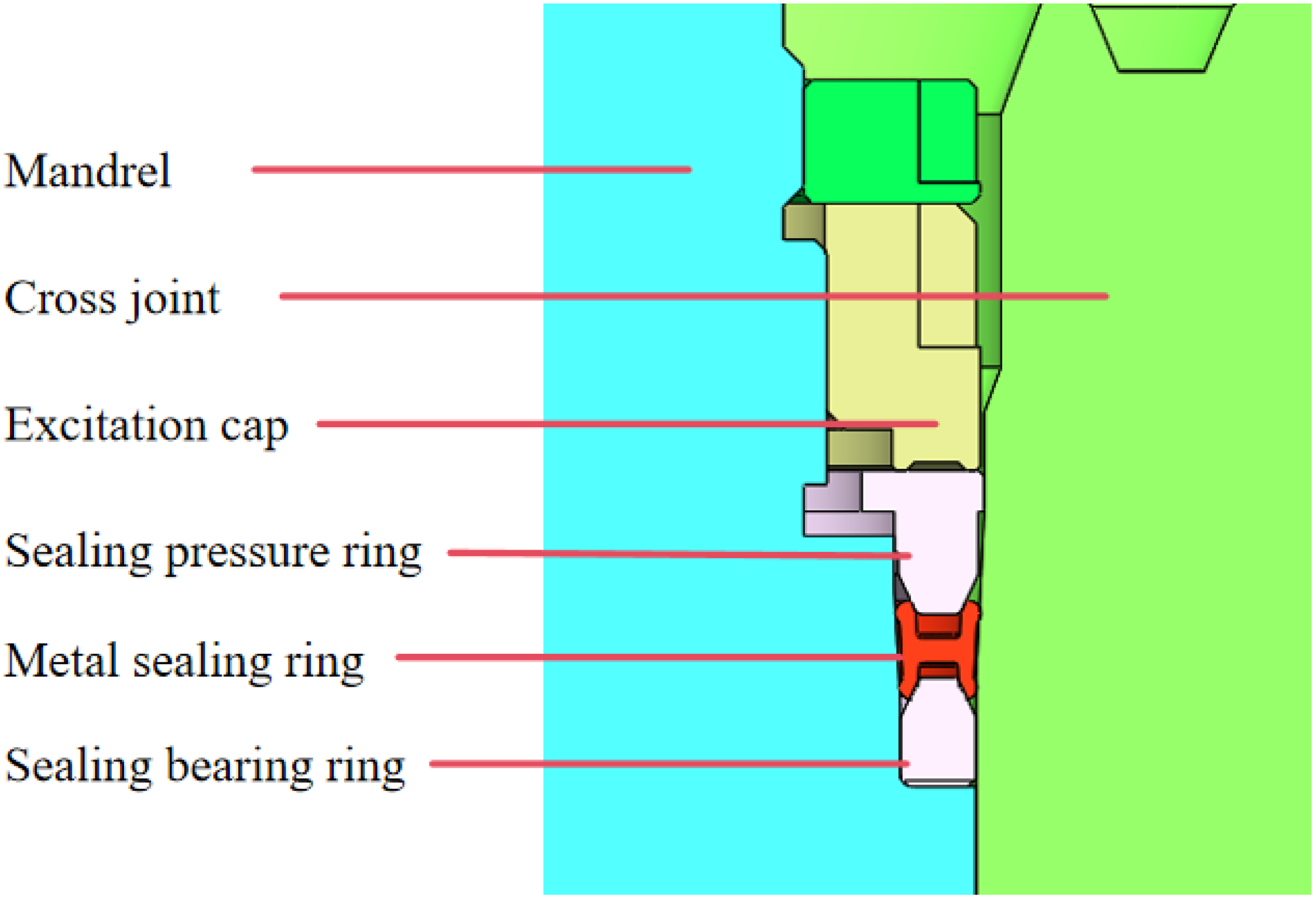
Sealing structure of casing hanger.
Sealing performance evaluation index
Sealing specific pressure requirements
According to the minimum sealing contact pressure selection criteria specified in UHP vessel design codes, the interfacial contact pressure must exceed the required sealing contact pressure, which is defined as 1.2–1.4 times the working pressure (Ji et al., 2024):

For 175 MPa operating conditions, the required sealing contact pressure is calculated to be 245 MPa.
Mises stress requirements
The Mises stress reveals stress concentration phenomena on sealing surfaces, where concentrated stress areas are more prone to crack initiation, potentially leading to seal failure and affecting equipment service life (Lihua and Yao, 2021). The sealing mechanism of metal seals requires sufficient plastic deformation at the sealing interface (Ding et al., 2024). To ensure reliable sealing performance, the maximum Mises stress in the sealing contact zone must satisfy the following conditions: (a) It must exceed 1.9 times the material's yield strength (the 316L stainless steel used for the seal ring has a yield strength of 218.11 MPa) (Zongliang, 2017; Yang and Wu, 2025; Li et al., 2024), to induce plastic flow of the metal and achieve intimate microsurface contact; (b) It must be strictly maintained below the ultimate tensile strength (502.7 MPa) to prevent material fracture failure (American Petroleum Institute, 2018): Effective contact width index

The contact width refers to the contact area formed between the sealing flange surface and the sealed component due to interference fit and friction during the compression process (Wei, 2020). The effective contact width refers to the width of the sealing surface where the contact stress reaches the required minimum contact stress. An insufficient contact width shortens the fluid permeation path, making it prone to creep and sealing failure. A larger effective contact width increases the resistance that fluid leakage needs to overcome, thereby improving sealing performance (Rao et al., 2024).
Contact uniformity index
The uneven distribution of contact pressure on sealing surfaces causes a sharp increase in plastic deformation, leading to differential deformation and flow across metal components. This results in reduced mechanical properties and compromises long-term stability. In this study, contact stress variance is adopted as the evaluation metric for contact uniformity (Yu, 2018). A smaller variance indicates better contact uniformity. By minimizing contact stress variance while maintaining sealing specific pressure, sealing reliability can be enhanced. The mathematical expression is:


Simulation analysis of temperature effects on seal performance
Considering the harsh field conditions in high-pressure operation zones, where wellhead temperatures experience extreme seasonal variations—with internal temperatures anticipated to fluctuate between 20°C and 125°C while external wall temperatures may range from −47°C to 100°C between summer and winter—this study focuses on evaluating the metal seal's ability to maintain stable sealing performance under such temperature extremes. Using a thermomechanical sequentially coupled approach, the research systematically examines how temperature variations during both heating to maximum (125°C) and cooling to minimum (−47°C) operational temperatures affect the sealing performance characteristics of the metal components.
Establishment of simulation model
The thermomechanical sequentially coupled method was employed for analysis. Sequential coupling refers to a computational approach where the results of the solid deformation field have minimal influence on the temperature field, while the temperature field calculations significantly affect the solid deformation field. The coupling process first performs a transient thermal analysis to calculate the temperature field distribution of the sealing system under extreme temperature conditions. Subsequently, the stabilized temperature field is mapped as predefined loads onto the structural model to solve for stress-contact behavior under combined thermal expansion and mechanical loading. The coupling process neglects convective heat transfer effects from fluids, considering only solid heat conduction and boundary heat exchange.
Simplified seal structure model and materials
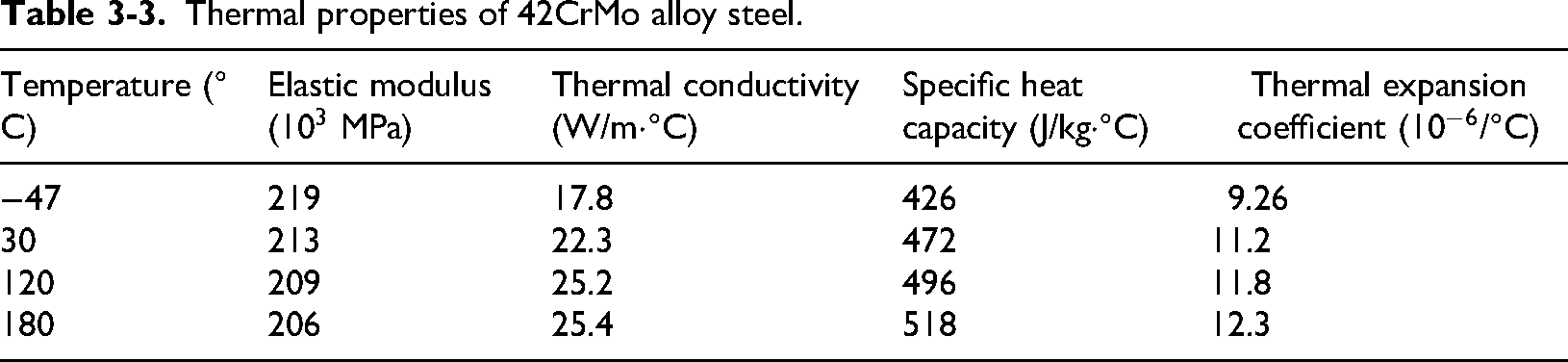
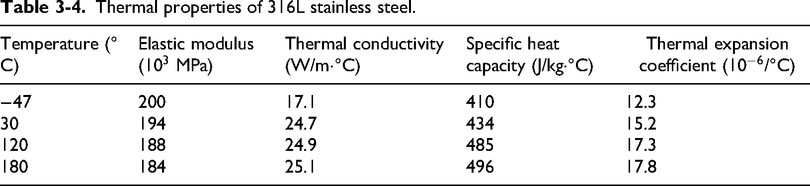
The casing head spool exhibits both geometric and load symmetry characteristics, with the sealing performance at this level being minimally affected by casing weight and spool axial loads, thus justifying the establishment of a two-dimensional axisymmetric simplified model of the sealing structure as illustrated in Figure 3-1, where the metal sealing ring is constructed from 316L stainless steel, the higher-hardness compression ring and base ring employ 42CrMo alloy steel, the hanger material consists of 718 alloy, and the spool utilizes 410 stainless steel, with detailed material parameters provided in Table 3-1, Table 3-2, Table 3-3, and Table 3-4.
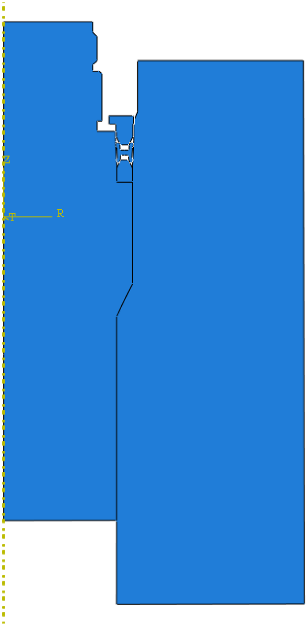
Simplified seal structure model.
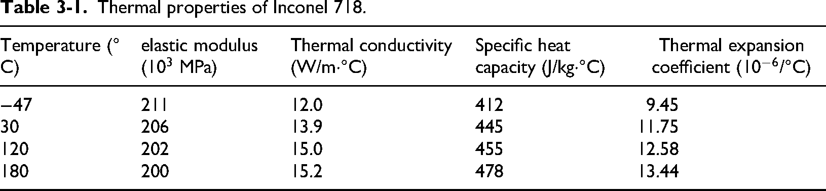
Thermal properties of Inconel 718.
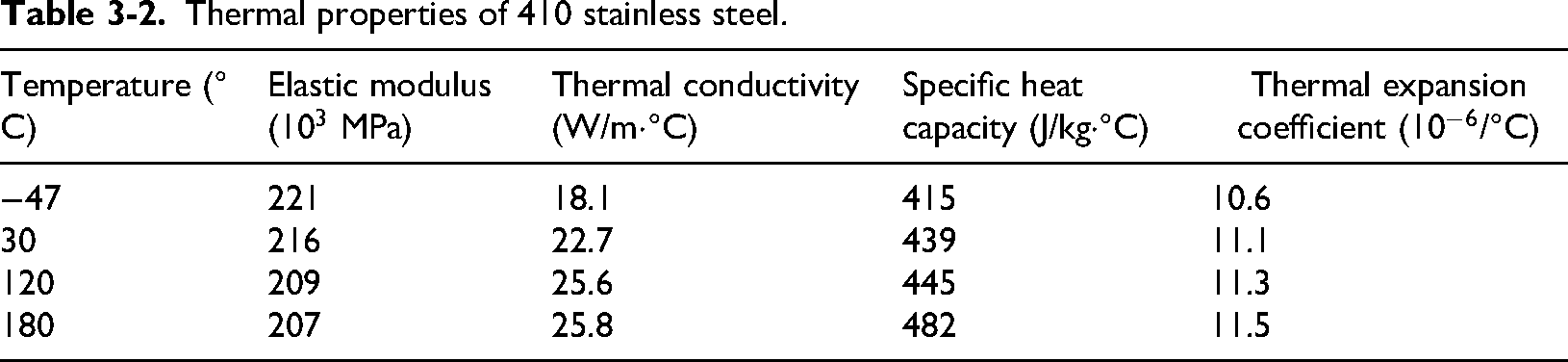
Thermal properties of 410 stainless steel.
Thermal properties of 42CrMo alloy steel.
Thermal properties of 316L stainless steel.
Boundary conditions
In terms of structural mechanics analysis, a static, general analysis step from the Abaqus/Standard solver was employed, as illustrated in Figure 3-2(a). The boundary conditions were set as follows: the left side represents the mandrel interior, while the right side corresponds to the outer wall surface of the spool structure, with corresponding temperature loads applied on both sides to simulate the heat conduction process under actual operating conditions. Regarding structural mechanical analysis, demonstrated in Figure 3-2(b), the boundary conditions were configured through three key steps: first, the integrated model components including the mandrel, spool, and compression ring were simplified as rigid bodies with fixed constraints applied at reference points to restrict overall displacement; second, the temperature field obtained from thermal analysis was mapped as predefined field loads onto the structural model; finally, to simulate the preload state of the sealing system, a downward axial enforced displacement load was applied at the compression ring position to generate appropriate compressive deformation in the sealing ring.
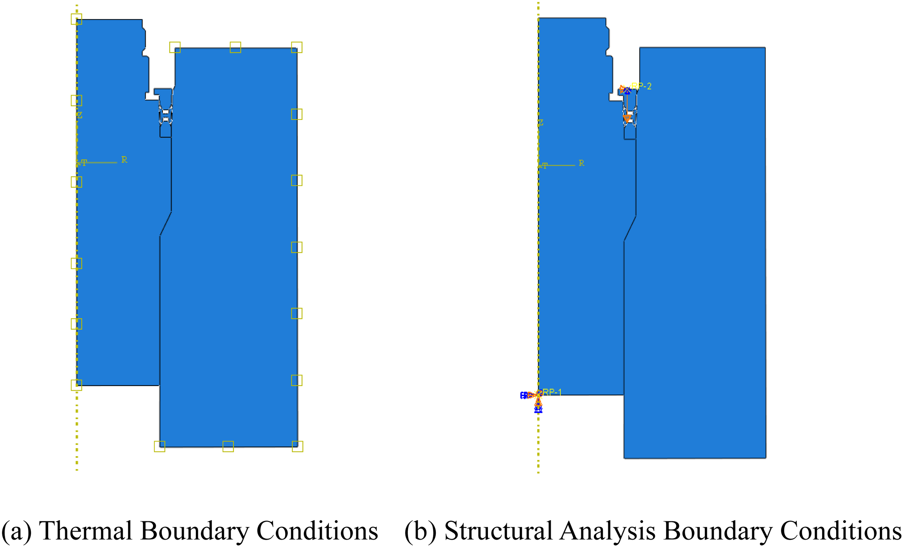
Configuration of boundary conditions. (a) Thermal boundary conditions. (b) Structural analysis boundary conditions.
Mesh independence verification
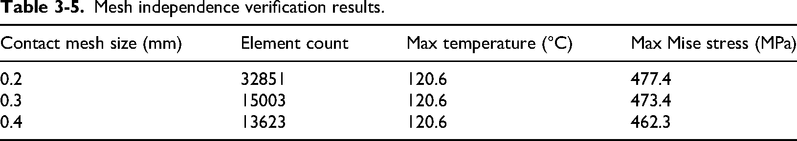
The meshing model is shown in Figure 3-3. A two-dimensional four-node bilinear reduced integration element (CAX4R) suitable for axisymmetric analysis was selected as the basic element type (Yang and Wu, 2025). Considering the steep stress gradients in the contact region of the seal ring, local mesh refinement was applied in this area to more accurately capture the stress and strain distribution on the contact surfaces. The maximum temperature and maximum Mises stress of the seal ring were used as criteria for assessing mesh independence. As presented in Table 3-5, under the three mesh sizes, the maximum temperature of the seal ring remains consistently at 120.6 °C, while the maximum Mises stresses are 477.4 MPa, 473.4 MPa, and 462.3 MPa, respectively. The relative deviation of the stress result between the 0.3 mm mesh and the finest 0.2 mm mesh is merely 0.84%, indicating that the 0.3 mm mesh has achieved a converged solution. Balancing computational accuracy and efficiency, the 0.3 mm mesh with a total of 15,003 elements was adopted for all subsequent analyses.
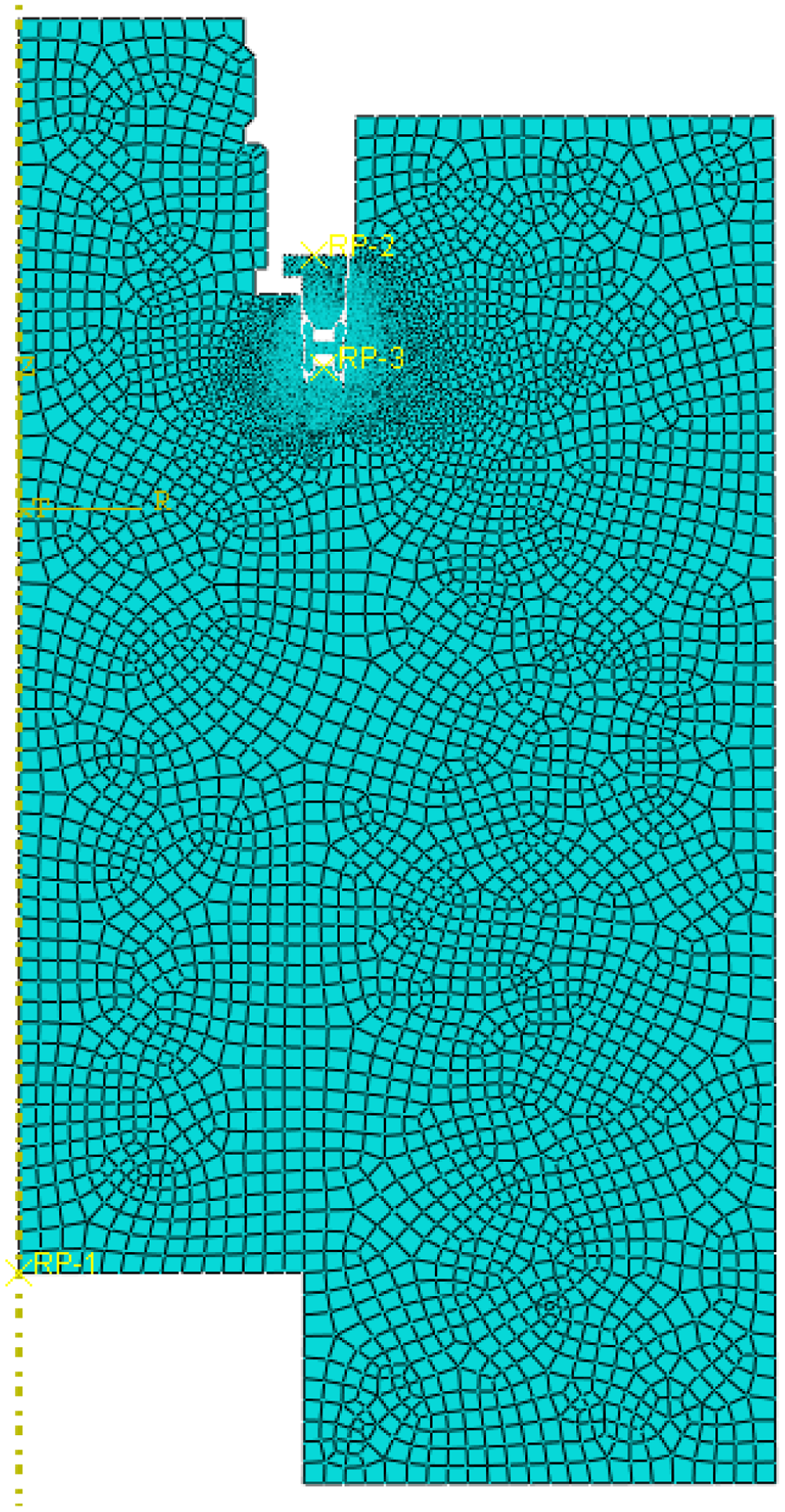
Grid division.
Mesh independence verification results.
Simulation experimental protocol.
Simulation experimental content
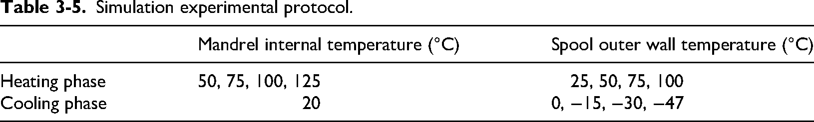
As detailed in Table 3-1, the experimental protocol comprised two thermal phases: During the heating phase, the mandrel internal temperature was progressively set to 50°C, 75°C, 100°C, and 125°C, while the corresponding spool outer wall temperatures were maintained at 25°C, 50°C, 75°C, and 100°C respectively, preserving a consistent 25°C thermal differential to simulate the temperature gradient evolution between mandrel and spool under high-temperature conditions, thereby analyzing the sealing structure's performance response to differential thermal expansion. In the cooling phase, the mandrel internal temperature was fixed at 20°C (minimum operating temperature) with the spool outer wall temperatures sequentially set to 0°C, −15°C, −30°C, and −47°C to simulate cold contraction effects under low-temperature conditions, enabling investigation of stress evolution and contact characteristics variation within the sealing structure during rapid temperature decline.
Influence of heating process on metal seal performance
As revealed in Figure 3-4, the temperature distribution of the metal sealing ring demonstrates distinct response characteristics to external thermal variations: when subjected to maximum external temperatures of 50°C, 75°C, and 100°C, the seal's bulk temperature stabilizes within 27–28°C, 52–53°C, and 77–78°C respectively, exhibiting a linear tracking relationship with external temperature rise; however, when the external temperature reaches 125°C, the seal undergoes an approximately 20°C step-change temperature jump, ultimately stabilizing at 120°C.
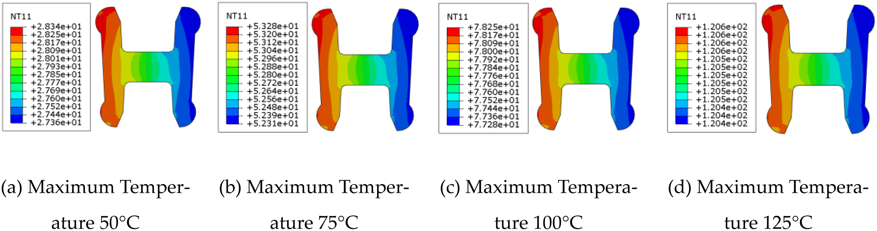
Temperature distribution of metal sealing ring. (a) Maximum temperature 50f . (b) Maximum temperature 75f . (c) Maximum temperature 100 r. (d) Maximum temperature 125 r.
The stress nephogram of the metal sealing ring under high-temperature conditions (Figure 3-5) reveals that the stress distribution pattern remains stable throughout the entire temperature rise process from 50°C to 125°C, with stress values showing a gradual increasing trend following temperature elevation. The maximum stress value merely increases marginally from 470.3 MPa to 473.4 MPa, representing a negligible growth of only 0.6%. This demonstrates that the stress distribution characteristics of the sealing ring exhibit minimal sensitivity to temperature variations within this high-temperature range.
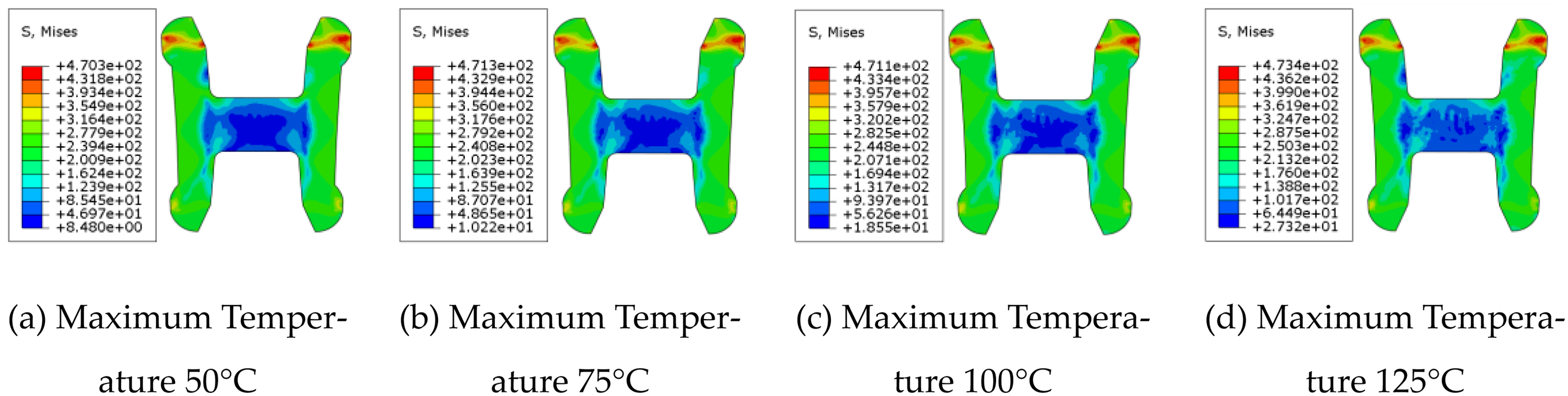
The stress nephogram of the metal sealing ring under high-temperature conditions. (a) Maximum temperature 50ur. (b) Maximum temperature 75ur. (c) Maximum temperature 100re. (d) Maximum temperature 125re.
Based on the contact path illustrated in Figure 3-6(a), the contact stress distribution along the sealing ring's interface was extracted. The simulation results indicate consistent contact stress distribution characteristics across all temperature stages, therefore only the representative distribution at the 25°C–50°C phase is presented in Figure 3-6(b). Analysis reveals that the contact stress on all four sealing surfaces exceeds the minimum required sealing specific pressure. The effective contact width is defined as the region where contact stress surpasses the required sealing specific pressure, with narrower curve profiles indicating reduced effective contact width on the corresponding sealing surfaces.
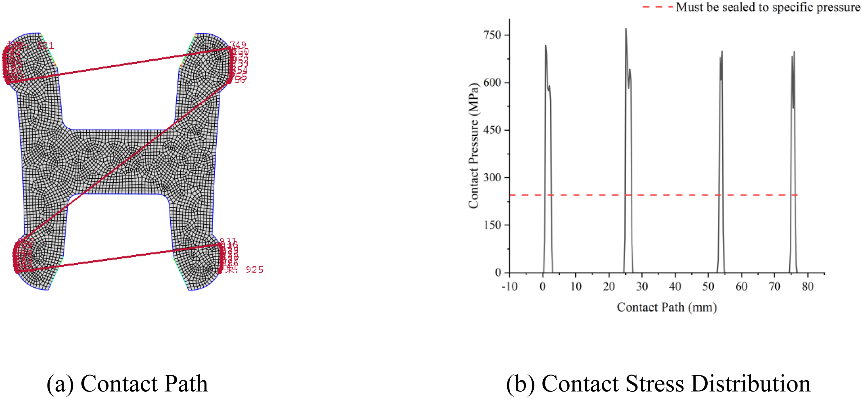
Contact stress distribution along the contact path. (a) Contact path. (b) Contact stress distribution.
Comparison of sealing performance during temperature rise to 125°C is shown in Figure 3-7. The results demonstrate that the effective contact width remains relatively constant throughout the temperature range, indicating minimal sensitivity of the seal's contact width to temperature variations. The contact stress variance exhibits fluctuating behavior, with the average variance at peak temperatures (100°C and 125°C) decreasing by approximately 5.3% compared to that at lower temperatures (50°C and 75°C). This suggests a more uniform distribution of contact stress under elevated temperature conditions.
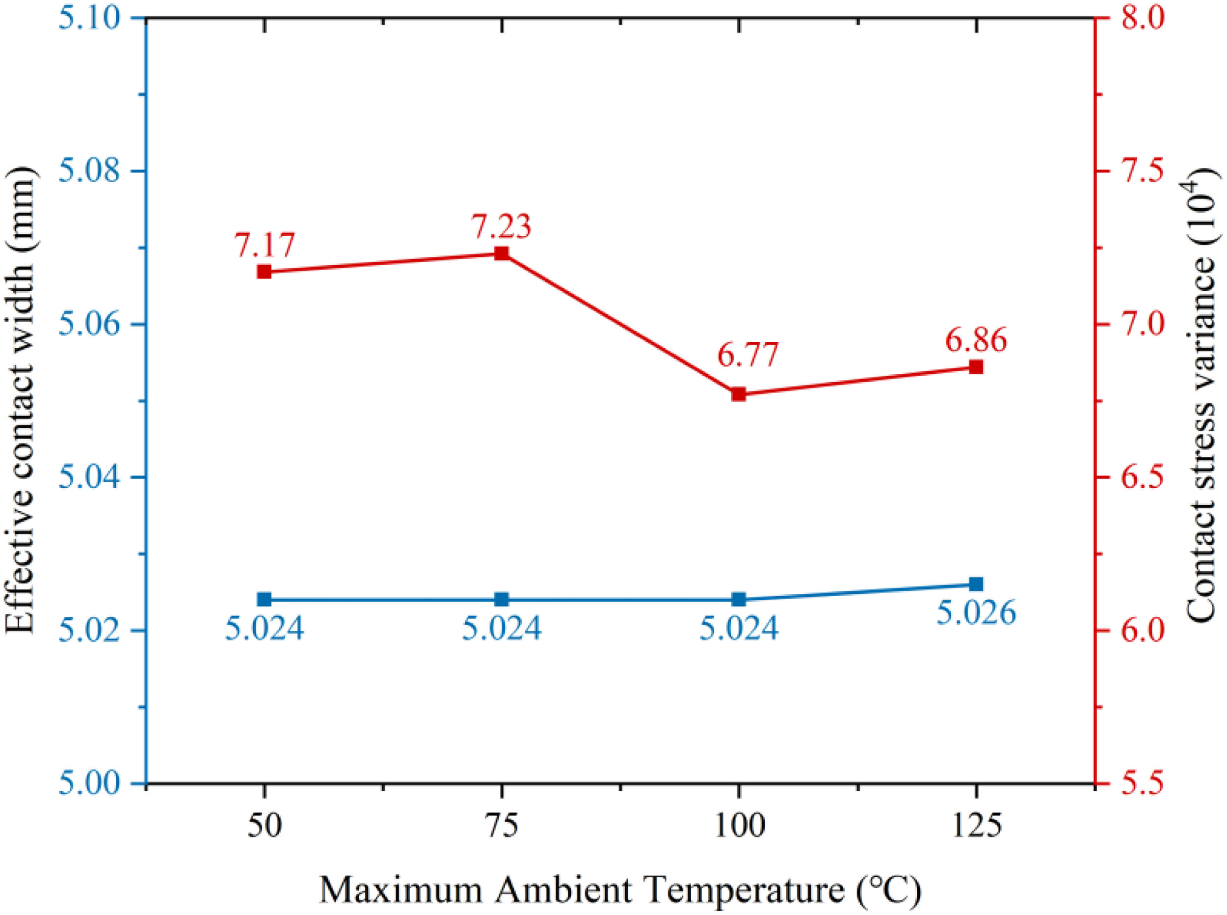
Comparison of effective contact width and contact stress variance of the sealing ring during heating.
Based on the aforementioned analysis, when the temperature increases from 50°C to 125°C, the stress distribution and effective contact width of the metal sealing ring exhibit low sensitivity to temperature variations. However, under elevated temperature conditions, the contact stress variance decreases, resulting in a more uniform distribution of contact stress.
Impact of cooling process on metal seal performance
As depicted in Figure 3-8, the steady-state temperature distribution of the metal sealing ring under varying environmental conditions reveals a consistent thermal response pattern: when the ambient temperature reaches a minimum of 0°C, the bulk temperature of the seal stabilizes within 1–3°C; as the environment cools to −15°C, the temperature is maintained between −10°C and −12°C; with further reduction to −30°C, the temperature remains confined to the −22°C to −25°C range; and under extreme cryogenic conditions of −47°C, the seal's temperature ultimately stabilizes within the −36°C to −40°C interval.
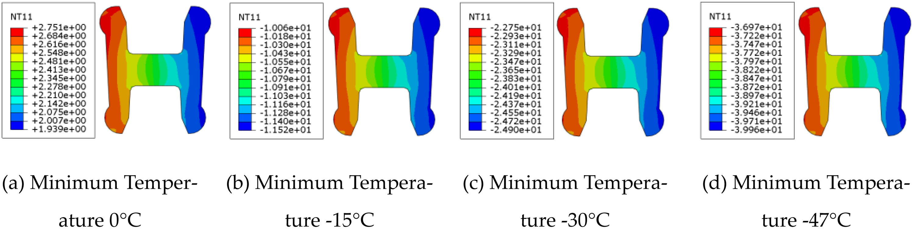
Temperature distribution of metal sealing ring. (a) Minimum temperature 0oC. (b) Minimum temperature −15°C. (c) Minimum temperature −30°C. (d) Minimum temperature −47°C.
Analysis of the stress nephogram (Figure 3-9) of the metal sealing ring under low-temperature conditions reveals that the morphology of the stress distribution remains unchanged and stable as the temperature decreases progressively from 0°C to −47°C. Concurrently, the stress values exhibit a gradual decreasing trend corresponding to the temperature reduction, with the maximum stress value slightly declining from 470.2 MPa to 468 MPa. This indicates that the stress distribution characteristics of the sealing ring are minimally influenced by temperature variations within this cryogenic range.
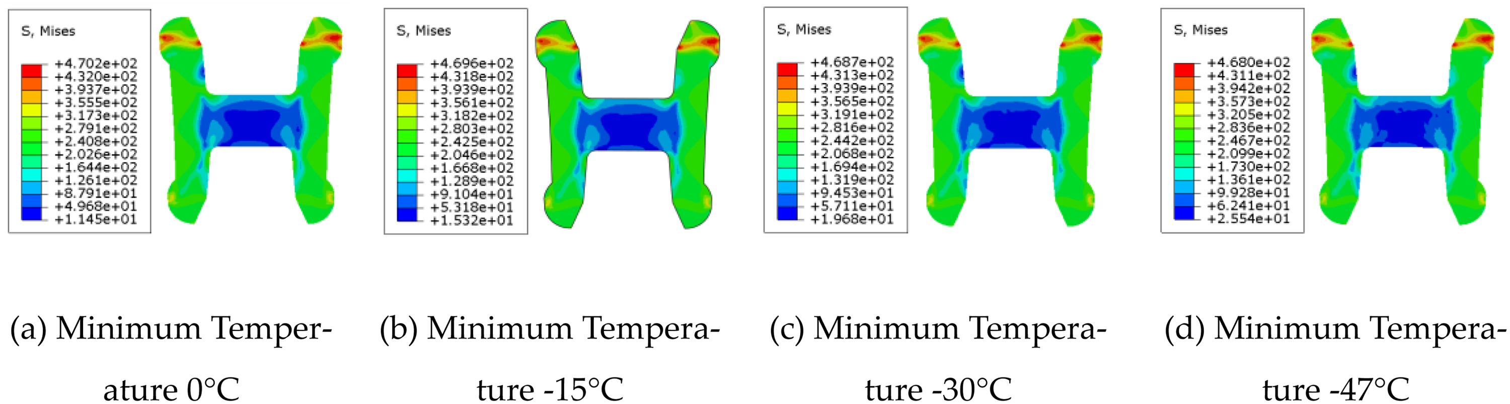
The stress nephogram of the metal sealing ring under low-temperature conditions. (a) Minimum temperature 0ep. (b) Minimum temperature −15°C. (c) Minimum temperature −30°C. (d) Minimum temperature −47°C.
Following the methodology outlined in the previous section, the contact stress along the sealing ring's contact path and the effective contact width were extracted, with the results presented in Figure 3-10. Within the ambient temperature range of 0°C to −47°C, both the effective contact width and the contact stress variance of the metal sealing ring demonstrate excellent stability. Temperature variations exhibit minimal influence on these two key sealing performance indicators, indicating that the sealing ring maintains stable and reliable sealing performance throughout this cryogenic range while effectively preserving the integrity of the sealing contact interface.
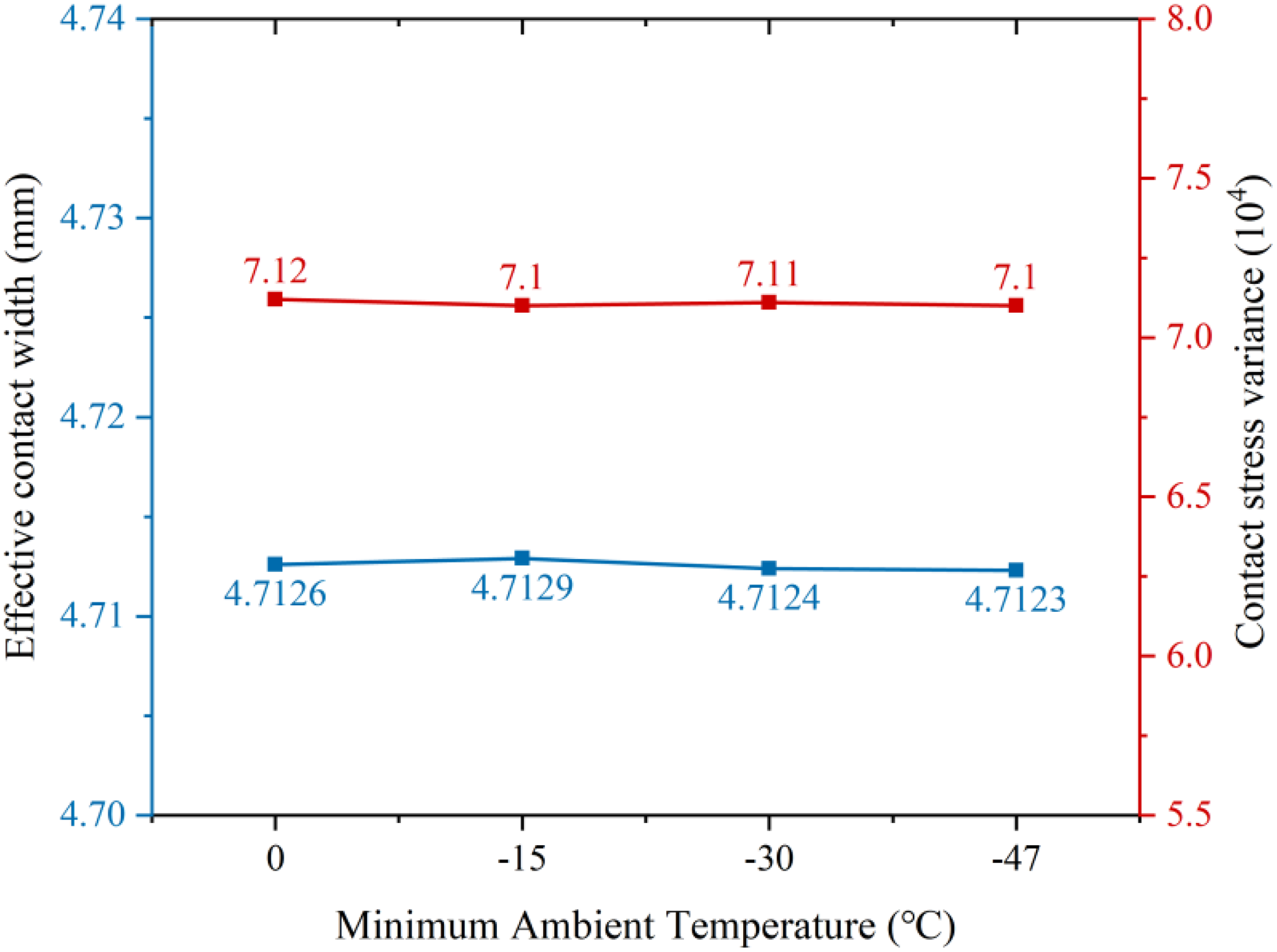
Comparison of effective contact width and contact stress variance of the sealing ring during cooling.
Based on the aforementioned analysis, as the temperature decreases from 0°C to −47°C, the stress distribution, effective contact width, and contact uniformity of the metal sealing ring all exhibit low sensitivity to temperature variations. This characteristic ensures stable sealing performance within this cryogenic temperature range, enabling the sealing ring to effectively maintain its sealing contact integrity.
Numerical analysis of sealing performance under 175 MPa thermomechanical coupling conditions
In practical engineering applications, casing head hangers are invariably subjected to the combined effects of UHP (175 MPa) and extreme temperatures. This section focuses on investigating the influence of different installation preload magnitudes on sealing ring performance under such extreme temperature and UHP conditions, aiming to evaluate the sealing reliability in complex operational environments. Parametric analysis has been widely adopted in offshore oil and gas equipment research to investigate the effects of key design variables on structural mechanical responses (Tang et al., 2024; Liu, 2020).
Simulation protocol and boundary condition configuration
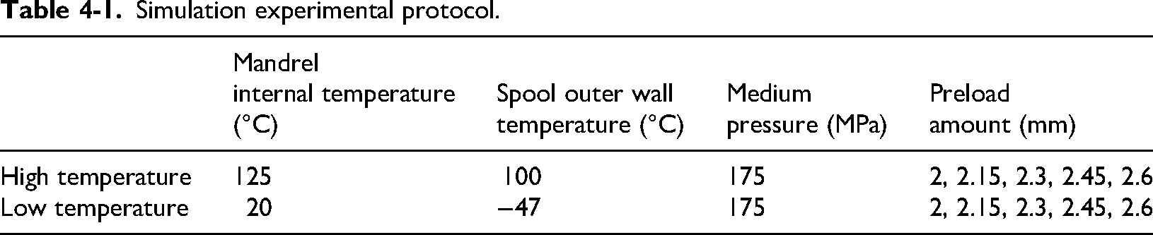
The specific operational parameters for the simulation experiments are detailed in Table 4-1. Under high-temperature conditions, the maximum internal temperature of the mandrel reaches 125°C, while the highest external wall temperature of the spool is 100°C. In low-temperature environments, the minimum internal temperature of the mandrel is maintained at 20°C, and the lowest external wall temperature of the spool drops to −47°C. Based on these two extreme temperature scenarios combined with the 175 MPa UHP condition, this study analyzes the variation patterns of sealing performance across a preload range of 2.0 to 2.6 mm.
Simulation experimental protocol.
Boundary condition setup is illustrated in Figure 4-1. The loads are applied in two analysis steps: (1) A vertically downward enforced displacement is applied to the compression ring, while the temperature field obtained from the thermal analysis is mapped onto the model as a predefined field load; (2) A medium pressure of 175 MPa is applied to the red region indicated in Figure 4-1.
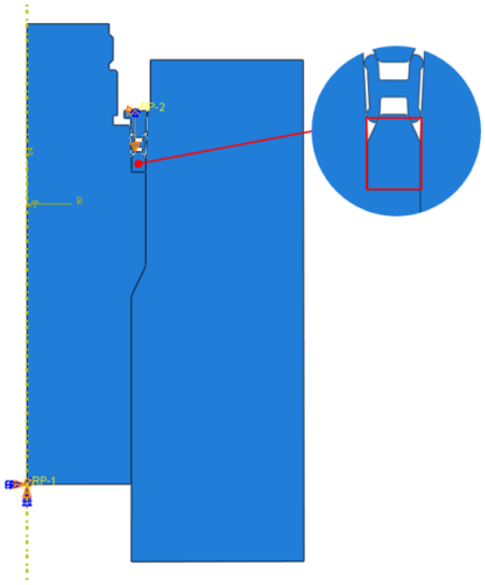
Configuration of boundary conditions.
Analysis of preload effects under high temperature and 175 MPa UHP conditions
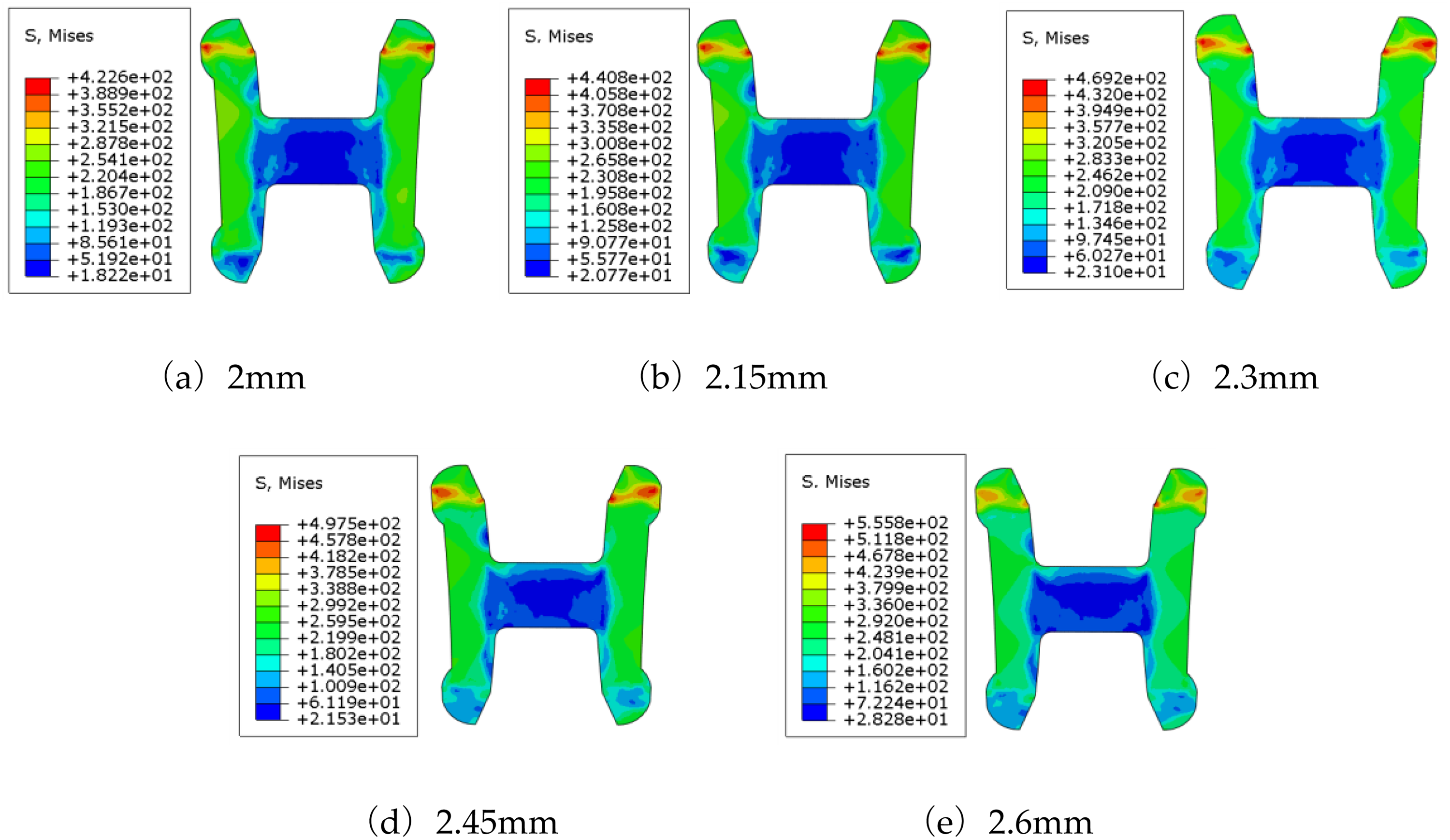
Figure 4-2 illustrates the stress distribution characteristics of the sealing ring under varying preload magnitudes in high-temperature environments. The analysis results indicate that stress concentration consistently occurs at the upper boss surface of the sealing ring across all preload conditions, extending from the contact surface to the inner corner, thereby constituting a critical failure-risk zone for the metal seal. As the preload increases, the stress concentration becomes more pronounced, accompanied by elevated stress values. When the preload reaches 2.6 mm, the maximum von Mises stress attains 561 MPa, exceeding the tensile strength limit of the sealing ring material. This leads to structural failure and complete loss of sealing functionality.

The effect of preloading conditions on the stress distribution of sealing rings under high-temperature and high-pressure conditions. (a) 2 mm, (b) 2.15 mm, (c) 2.3mm, (d) 2.45 mm, (e) 2.6 mm.
Figure 4-3 compares the maximum von Mises stress, effective contact width, and contact stress variance of the sealing ring under varying preload conditions in a coupled UHP and low-temperature environment. Analysis reveals that both the effective contact width and maximum von Mises stress exhibit a positive correlation with preload magnitude. When the preload increases to 2.6 mm, the effective contact width reaches 6.28 mm, representing a 17.4% improvement compared to the 2.45 mm preload condition; however, at this point, the maximum von Mises stress exceeds the material's tensile strength. In contrast, the contact stress variance decreases with increasing preload. A lower variance indicates more uniform distribution of contact stress between the sealing ring and the sealing wall surface, reflecting a more stable contact condition.
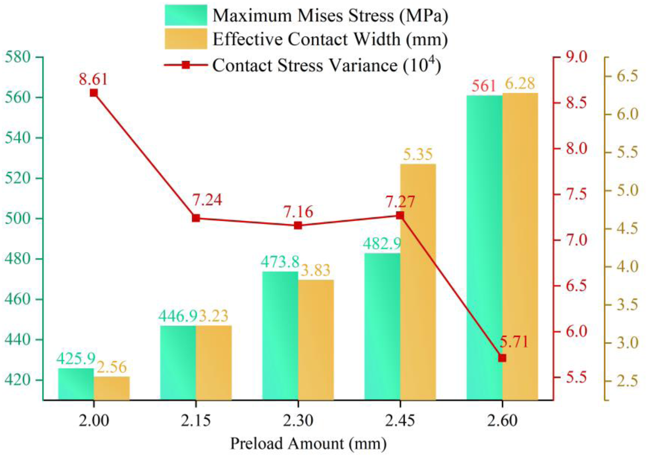
The influence pattern of different preloading conditions on sealing performance under high-temperature and high-pressure conditions.
Based on the comprehensive analysis, under the combined 175 MPa UHP and high-temperature conditions, increasing the preload significantly enhances the effective contact width, thereby amplifying the flow path resistance against fluid leakage and improving the overall sealing effectiveness. However, it is crucial to strictly control the stress imposed on the sealing ring to prevent it from exceeding the material's ultimate strength. Simultaneously, a higher preload contributes to reduced contact stress variance, promoting more uniform and stable contact conditions.
Analysis of preload effects under low temperature and 175 MPa UHP conditions
Figure 4-4 illustrates the stress distribution characteristics of the sealing ring under different preload conditions. The analysis results indicate that stress concentration consistently occurs at the upper boss surface of the sealing ring across all preload levels, extending from the contact surface to the inner corner and forming a critical risk zone for the metal seal. As the preload increases, the loading on the lower boss is significantly enhanced, resulting in a larger effective contact area with the mating surface. When the preload reaches 2.6 mm, the maximum von Mises stress attains 555.8 MPa, exceeding the tensile strength limit of the sealing ring material. At this point, the sealing ring undergoes structural failure and loses its sealing functionality.
The effect of preloading conditions on the stress distribution of sealing rings under low temperature and high pressure conditions. (a) 2 mm, (b) 2.15 mm, (c) 2.3 mm, (d) 2.45 mm, (e) 2.6 mm.
Figure 4-5 reveals the influence of preload magnitude on sealing ring performance under coupled UHP and low-temperature conditions: as the preload increases, both the maximum von Mises stress and the effective contact width significantly increase, while the contact stress variance decreases. This indicates that increasing the preload not only enhances the contact pressure but also expands the sealing contact area, resulting in a more uniform stress distribution and thereby improving sealing stability. However, when the preload reaches 2.6 mm, the maximum von Mises stress attains 555.8 MPa, exceeding the tensile strength limit of the sealing ring material. This preload magnitude is therefore unsuitable for practical installation conditions.

The influence patterns of different preloading conditions on sealing performance under low-temperature and high-pressure conditions.
Comparative analysis of metal seal performance under high/normal/low temperature environments
Using room temperature conditions as a baseline, this section comparatively analyzes the influence trends of both low-temperature and high-temperature extreme environments on sealing performance under 175 MPa UHP conditions, aiming to determine the optimal installation preload that ensures stable sealing effectiveness under both UHP and extreme temperatures.
As shown in Figure 4-6, comparative analysis of the maximum von Mises stress of the sealing ring under various preload levels reveals: the stress experienced by the sealing ring exhibits a positive correlation with preload magnitude, where greater preload results in higher stress; under identical preload conditions, temperature increase leads to a minor elevation in stress; to ensure sealing performance, the stress on the sealing ring must exceed 1.9 times the material yield strength (411 MPa) yet remain below the tensile strength across low-temperature, normal-temperature, and high-temperature environments. Consequently, the installation preload should not exceed 2.45 mm.
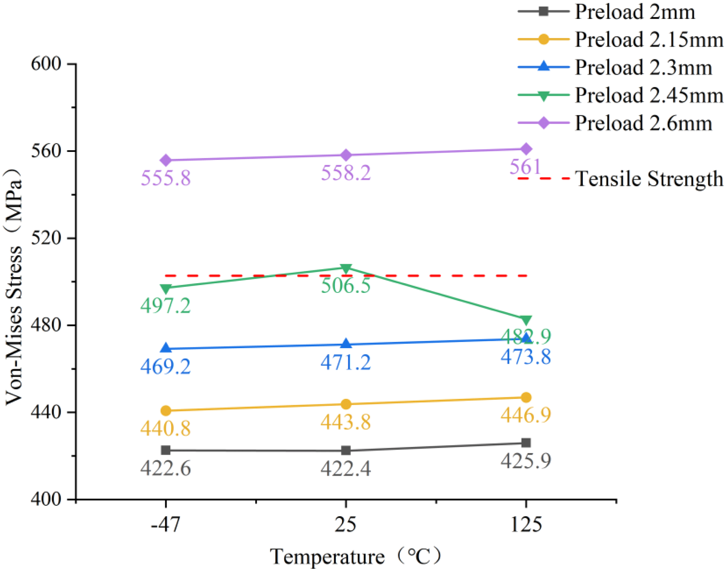
Comparative analysis of maximum von Mises stress.
Figure 4-7 presents a comparative analysis of the effective contact width under various preload conditions. The results demonstrate that when the preload increases from 2.3 mm to 2.45 mm, the effective contact width shows a remarkable 51% enhancement. Under preload conditions below 2.3 mm, the high-temperature environment promotes a slight increase in the effective contact width. However, when the preload exceeds 2.45 mm, the influence of temperature variations on the effective contact width becomes negligible.
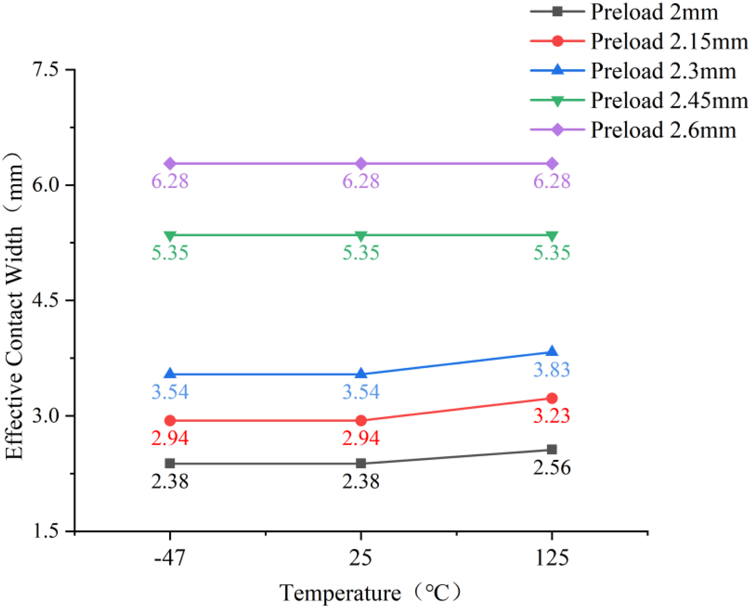
Comparative analysis of effective contact width.
Figure 4-8 presents a comparative analysis of the contact stress variance under various preload conditions. The results indicate that as the preload increases, the contact stress variance in the sealing ring's contact region gradually decreases, leading to a more uniform stress distribution and improved contact stability. When the preload exceeds 2 mm, the influence of temperature variations on the contact stress distribution diminishes significantly, with the amplitude of change in contact stress variance markedly reduced from low to high temperature conditions.
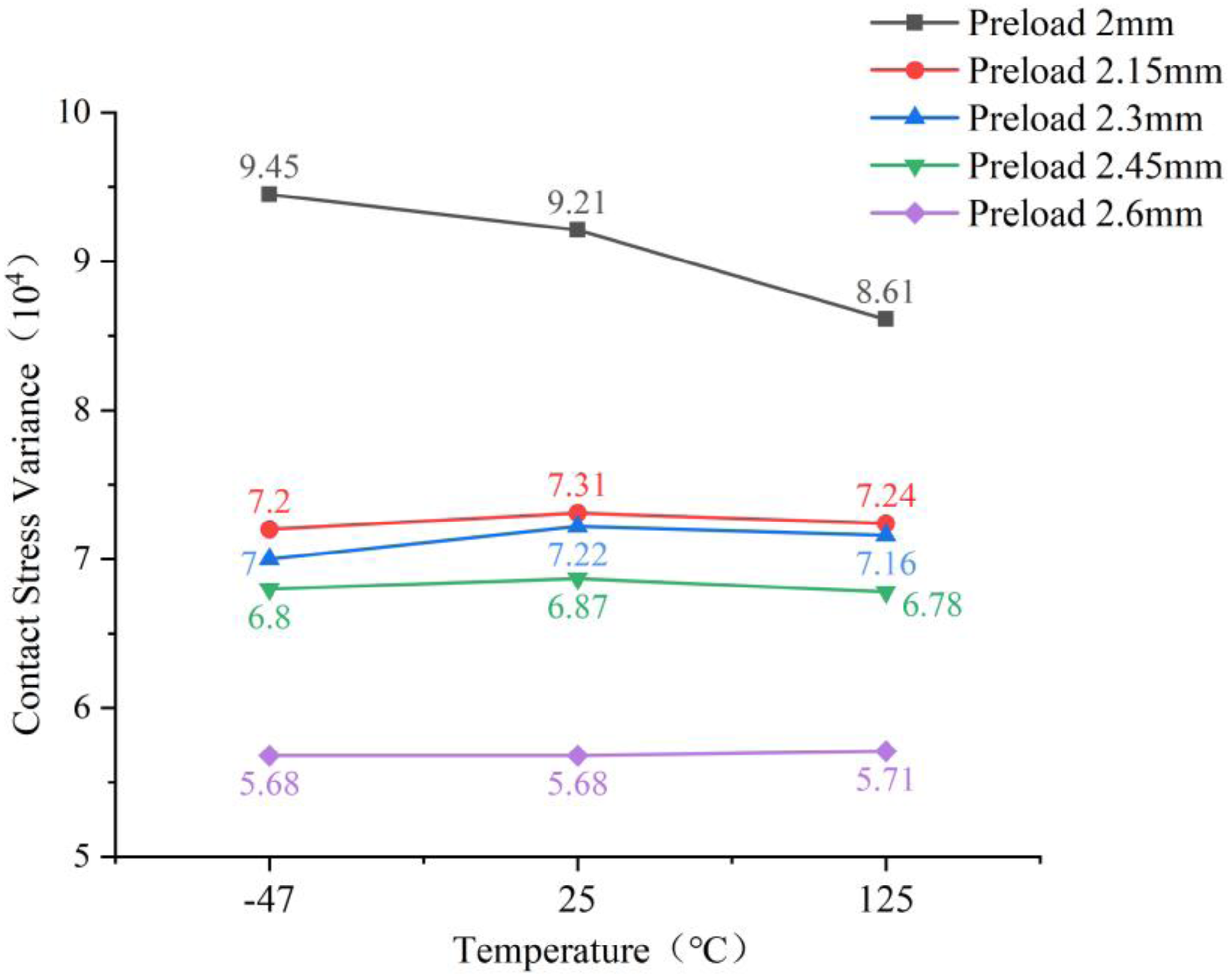
Comparative analysis of contact stress variance.
Comprehensive analysis of sealing performance under 175 MPa UHP conditions across both low and high temperature environments demonstrates that within the tested temperature range, the correlation between temperature and sealing performance is relatively weak. When the preload is controlled below 2.45 mm, increasing the preload results in a significant expansion of the effective contact width and improved uniformity of contact stress distribution. Therefore, selecting an installation preload close to 2.45 mm ensures both reliability and stability of the sealing system under UHP and extreme temperature conditions.
Experimental validation of metal seal reliability under coupled high/low temperature and 175 MPa UHP conditions
Experimental objectives
The experiment aims to validate the sealing reliability of casing head spool metal seals under the combined effects of high/low temperature and 175 MPa working pressure. The experimental data will provide critical verification for the sealing design of wellhead equipment in extreme environments such as ultra-deep wells and polar oil/gas fields.
Experimental methodology
This study employs a “temperature-pressure dual-factor coupled loading” method, conducting experimental validation on a self-developed 8 1/8″ full-metal mandrel-type casing hanger specimen. Temperature loads are applied via a temperature-controlled environmental chamber, while pressure loads are implemented using nitrogen medium injected through the pressure test inlet (Figure 5-1). The preload in the experiment was applied using a torque control method. A calibrated hydraulic torque wrench was employed to apply the specified torque to the lockdown screws of the casing head. The relationship between the applied torque and the resulting axial compression of the seal assembly was established through prior calibration tests conducted on a load frame. Based on the calibration curve, the torque value selected for this experiment corresponds to an equivalent preload compression of approximately 2.45 mm for the seal ring, which is consistent with the optimal preload value determined by the simulation analysis.
8 1/8″ full-metal sealing mandrel-type casing hanger. (a) Schematic diagram of experimental setup, (b) temperature-controlled environmental chamber.
Experimental temperature loading profiles. (a) Heating curve, (b) cooling curve.
The experiment comprises two representative operational conditions:
125°C High Temperature/175 MPa UHP Coupled Condition: The environmental chamber is heated to 125°C (temperature fluctuation ±1°C) at a controlled ramp rate using a PID temperature control system. After temperature stabilization, nitrogen medium is injected via a high-pressure pneumatic intensifier pump to reach 175 MPa (pressure fluctuation ±0.5 MPa) in graduated pressure increments. The system is maintained at pressure for 15 min while the pressure decay curve is recorded. −47°C Low Temperature/175 MPa UHP Coupled Condition: The environmental chamber is cooled to −47°C (temperature fluctuation ±1.5°C) using a liquid nitrogen refrigeration system. The same pressure loading procedure is applied to complete the 175 MPa pressure-holding test.
A pressure drop not exceeding 3.45 MPa during the stabilization period, in accordance with the provisions of API 6A standard, the leakage rate shall not exceed 1 × 10⁻⁴ Pa·m3/s. A sealing ring is deemed qualified if there is no detectable leakage (American Petroleum Institute, 2018).
Mathematical expression for leakage rate:
The volume of the sealing system was measured to be 3.92 × 10⁻⁵ m3.
Analysis of experimental results
As shown in Figure 5-3, the experimental results for the 125°C high temperature/175 MPa UHP coupled condition demonstrate stable temperature maintenance throughout the pressurization process, with a maximum temperature of 125.2°C. When the pressure reached 179.5 MPa, the pressure-holding phase was initiated. After 15 min, the pressure stabilized at 178.91 MPa, resulting in a pressure drop of 0.67 MPa, the leakage rate was 0.88 × 10⁻⁵ Pa·m3/s. No gas leakage was detected during the entire test procedure.
Experimental results of 125°C high temperature/175 MPa ultrahigh pressure coupling test.
As shown in Figure 5-4, the experimental results for the −47°C low temperature/175 MPa UHP coupled condition indicate stable temperature maintenance throughout the pressurization process, with a minimum temperature of −47.2°C. When the pressure reached 178.73 MPa, the pressure-holding phase was initiated. After 15 min, the pressure stabilized at 177.58 MPa, resulting in a pressure drop of 1.16 MPa, the leakage rate was 0.27 × 10⁻⁴ Pa·m3/s. No gas leakage was observed during the entire test.
Experimental results of −47°C low temperature/175 MPa ultrahigh pressure coupling test.
Figure 5-5 presents a comprehensive liquid penetrant inspection conducted on the sealing assembly after testing. The inspection procedure included solvent cleaning pretreatment, penetrant application, a 30-min developer dwelling time, and 20× magnification observation under 365 nm ultraviolet light. The results revealed no surface defects such as cracks or porosity in all inspected components (including the metal sealing ring, compression ring, and pressure-bearing ring). Specifically, the working surface of the metal sealing ring maintained excellent material continuity. Combined with the pressure test results, the metal seal of the casing head spool fully satisfies the sealing requirements under the coupled conditions of extreme temperatures and 175 MPa UHP.

Liquid penetrant inspection.
Conclusion
A sequentially coupled thermomechanical numerical simulation was conducted to analyze the stress distribution evolution and temperature sensitivity characteristics of the metal seal ring during both heating and cooling processes. The results indicate that the stress distribution and effective contact width of the seal ring exhibit low sensitivity to temperature variations. This insensitivity can be attributed to the fact that the primary deformation of the seal ring is plasticity-dominated from the initial mechanical preload stage, whereas the subsequent thermal strains are predominantly elastic and relatively small in magnitude, thereby exerting limited influence on the established contact state. Under elevated temperature conditions, the contact stress variance decreases by an average of 5.3%, indicating a more uniform contact stress distribution. This improvement results from thermal expansion partially relieving localized contact stress peaks across the sealing interface. The influence of different installation preloads within the range of 2.0–2.6 mm on the contact stress distribution, effective sealing width, and contact stress variance was analyzed under the combined effects of 175 MPa UHP and extreme temperatures. The results indicate that within the tested temperature range, the correlation between temperature and sealing performance is relatively weak. When the preload is controlled below 2.45 mm, increasing the preload significantly enhances the effective contact width and improves the uniformity of contact stress distribution. Therefore, selecting an installation preload close to 2.45 mm ensures both reliability and stability of the sealing system under UHP and extreme temperature conditions. Experimental validation on an 8 1/8″ all-metal sealing mandrel-type casing hanger demonstrated that under 15-min pressure hold tests, the system pressure drops were 0.67 MPa and 1.16 MPa for the 125 °C/175 MPa and −47 °C/175 MPa conditions, respectively. Combined with liquid penetrant inspection results, these tests confirm the short-term sealing reliability of the casing head hanger metal seal structure under the specific extreme conditions examined. The following limitations of this study should be acknowledged. The simulation model adopts a two-dimensional axisymmetric simplification, which does not account for three-dimensional effects such as manufacturing tolerances and nonuniform preloading. The material model employs constant room-temperature strength parameters and does not incorporate the variation of yield strength and tensile strength at elevated and cryogenic temperatures. The experimental validation was conducted at only two temperature extremes (−47 °C and 125 °C) with a 15-min hold duration. Future research may establish a three-dimensional full-scale model, incorporate temperature-dependent material parameters, and expand the experimental condition matrix to more comprehensively evaluate the long-term service reliability of the seal structure.
Footnotes
Funding
The authors disclosed receipt of the following financial support for the research, authorship, and/or publication of this article: This work was supported by the China National Petroleum Corporation Major Science and Technology Project, (grant number No. 2025ZG15).
Declaration of conflicting interests
The authors declared no potential conflicts of interest with respect to the research, authorship and/or publication of this article.
Data availability statement
All data generated or analyzed during this study are included in this published article.