
Abstract
This article introduces a novel control strategy aimed at improving the efficiency and stability of grid-connected photovoltaic (PV) systems by enhancing the performance of the single-ended primary inductor converter (SEPIC) integrated with a microinverter. Traditional control methods often fail to optimize both grid dynamic response and power quality simultaneously, especially in response to changing environmental conditions like solar irradiance and load fluctuations. In contrast, this research focuses on a specific and deliberate strategy. The key innovation lies in the simultaneous multiloop optimization of the SEPIC–microinverter system using the imperialist competitive algorithm (ICA). This approach involves using ICA to adjust the parameters of the inner current loop (using P control) and the outer voltage control loop (using proportional integral (PI) control) of the SEPIC converter to maintain DC voltage regulation in PV systems. We argue that our ICA-integrated approach can overcome the limitations of traditional control techniques (such as classic PI tuning) and previous research that mainly focused on single-loop optimization or isolated component improvements. The results of our study demonstrate the significant benefits of this co-optimization. Simulation results from MATLAB/Simulink, with pulse width modulation (PWM) control, confirm that this co-optimization leads to substantial improvements compared to conventional systems and standard control methods: a 60% reduction in settling time during transients (from 1.5 to 0.6 s), elimination of overshoot (which was around 20% in the uncompensated system), an increase in attenuation from 0.19 to 0.47, and improved oscillation suppression.
Introduction
Cleaning the planet is a global priority that aims to rid the Earth of pollution. To accomplish this, it is necessary to reduce carbon emissions. Renewable energy sources, such as wind and solar power, are considered the most effective solutions due to their benefits in decreasing reliance on pollution-emitting fossil fuels and improving energy security. Therefore, the integration of renewable energy sources is a critical step toward achieving a green and sustainable future (Abdelfattah et al., 2025; Awad et al., 2024; El-Rifaie et al., 2025; Kanwal et al., 2022; Priyadarshini et al., 2025). Among the various renewable technologies being implemented in modern power grids, photovoltaic (PV) systems have seen the fastest adoption, thanks to their availability and eco-friendliness. However, a significant challenge related to grid reliability and performance is intermittency. The introduction of microinverters, which convert the direct current (DC) output of each PV module into alternating current (AC) while providing effective performance controls, is viewed as a highly promising solution for enhancing the overall efficiency of the system output (Abbasi et al., 2022; Basu et al., 2025; Maamar et al., 2025).
The key advantage of the microinverter in conjunction with the single-ended primary inductor converter (SEPIC) converter is its capacity to operate in both buck and boost modes, allowing the output voltage from the photovoltaic system to vary in response to the input. For performance enhancement and stability of the overall system, the controlling scheme must be optimized during grid-connected operation (Heroual et al., 2025a; Paul et al., 2023a; Premkumar et al., 2020). The enhancement of the SEPIC-based microinverter aimed at improving the functionality of grid-connected photovoltaic systems is discussed. Under varying irradiance and grid disturbances, a sophisticated control scheme with maximum power point tracking (MPPT), aiming for power extraction maximization, ensures synchronism, and power quality (Adak and Cangi, 2024; Aliaga et al., 2022; Arunadevi et al., 2024; Hysa et al., 2025; Ibrahim et al., 2023c; Sutikno et al., 2023a).
A number of researchers have investigated the operation of microinverters, and their control methodologies aimed at enhancing the efficiency of photovoltaic systems. For instance, Heroual et al. (2025b) and Sutikno et al. (2023b) performed a physical security information management (PSIM)-based simulation with a BISOL BMO-250 PV module along with a P&O-MPPT controller to compare the six modified designs of SEPIC. Here, it was found that one design possessed voltage gain capability more than 10 times at a low duty cycle (0.8) with very little stress on switches; efficiencies were between 97.2% and 99.5%. The problem of stability was tackled in other studies. Sinha et al., (2025b) introduced an improved proportional-based current controller that modifies duty cycles dynamically for the consistent delivery of high-voltage reactive power during specific events. This MATLAB simulation validated that this approach effectively integrated overshoot size and completely eliminated steady-state error by differentiating these parameters (Abdelwahab et al., 2024; Ravindaran and Bella Bellie, 2023).
Furthermore, the most recent advancements pertained to grid-connected PV systems, enhancing control mechanisms. Helal et al. (2023) and Makram Kamel et al. (2025) proposed a design for a DC microgrid utilizing a PV source, which facilitated power distribution and ensured compatibility with the grid through voltages and currents controlled by a voltage source inverter (VSI).
The implementation of passive filtering improves signal quality, whereas proportional integral derevative (PID) controllers demonstrate superior performance relative to the conventional proportional integral (PI) controller in the presence of disturbances. The simulation outcomes confirmed the effectiveness of this approach (Hadi et al., 2024b; Helal et al., 2023; Menzri et al., 2024a; Sinha et al., 2025a).
Additional studies encompass converter design and the efficacy of inverters. For example, Díaz et al. (2023) and Joga et al. (2024) detailed a push-pull converter integrated with a hybrid MPPT algorithm and PI control, utilizing an H-bridge inverter that employs both cascaded PI and predictive control. This prototype attained an efficiency exceeding 99% in MPPT during conditions of partial shading. The work done by Chowdhury and Singh (2023) uses a virtual resistive impedance instead of an inductive impedance in three-phase grid-connected converters, thus providing better stability as compared to inductive harmony under MATLAB simulation. (Chowdhury and Singh, 2023; Elsayed et al., 2025; Maheshwari et al., 2025; Menzri et al., 2024b; Paul et al., 2023b; Saleeb et al., 2024) developed a transformer-less SEPIC with noncoupled inductors, which allowed high gain with reduced switch stress and simple control.
On the other hand, calibration methods for reloading based on noninteger controllers were assessed by Sreedevi and Hari Kumar (2023), aiming at enhanced frequency stability under different load and weather conditions. Among others, Battagiri and Kumar (2023) investigated grid stability during disturbances with synchronous generators, operating in transient mode. Varatharaju et al. (2023) implemented a dual predictive loop distributed control strategy for MPP tracking and power distribution, validated by simulations and prototypes. The novel enhanced interleaved SEPIC developed with crow search algorithm optimized PI control by Thangam and Vel (2023) is based on the conception of Obukhov et al. (2019) which gave a low ripple and high efficiency. Bhattacharya et al. (2023) presented a single-stage microinverter design with a resonant capacitor with coupled-inductor Ćuk Configuration, which reduced switching losses and improved efficiency.
Even though the research was quite extensive, it was still found that there were gaps. Many studies do not capture key areas like cost, size, and thermal management. Though a very high gain voltage has been attained in some designs, they often ignore the quality of grid voltage in addition to rapid recovery from disturbances (Chowdhury and Singh, 2023; Paul et al., 2023b; Ravikumar et al., 2025; Sutikno et al., 2023b). So do works related to MPPT and controller optimizations, which often do not present complete assessments of the full stability of the system in the steady state or transient conditions (Sreedevi and Hari Kumar, 2023; Thangam and Vel, 2023; Varatharaju et al., 2023). Moreover, analyses are usually based only on buck or boost operation, thus not capturing the bidirectional regulation advantage of SEPIC converters.
In order to optimize the two control loop systems with this imperialist competitive algorithm, what we need here is a hybridization of SEPIC-to-microinverter type converters. Indeed, the result of that is improving the transitory response, decreasing overshoot, and settling time and reducing total harmonic distortion (THD) from the output voltage. Different from previously conducted works which improved separately SEPIC efficiency and microinverter stability, this study merges both improvements in a single framework of control.
Here are the major contributions made by the paper:
Imperialist competitive algorithm (ICA)-based control strategy development for SEPIC microinverters; Enhancement of dynamic performance and stability for grid-connected PV systems; and Enhancement of grid power quality with THD and voltage stability reduction.
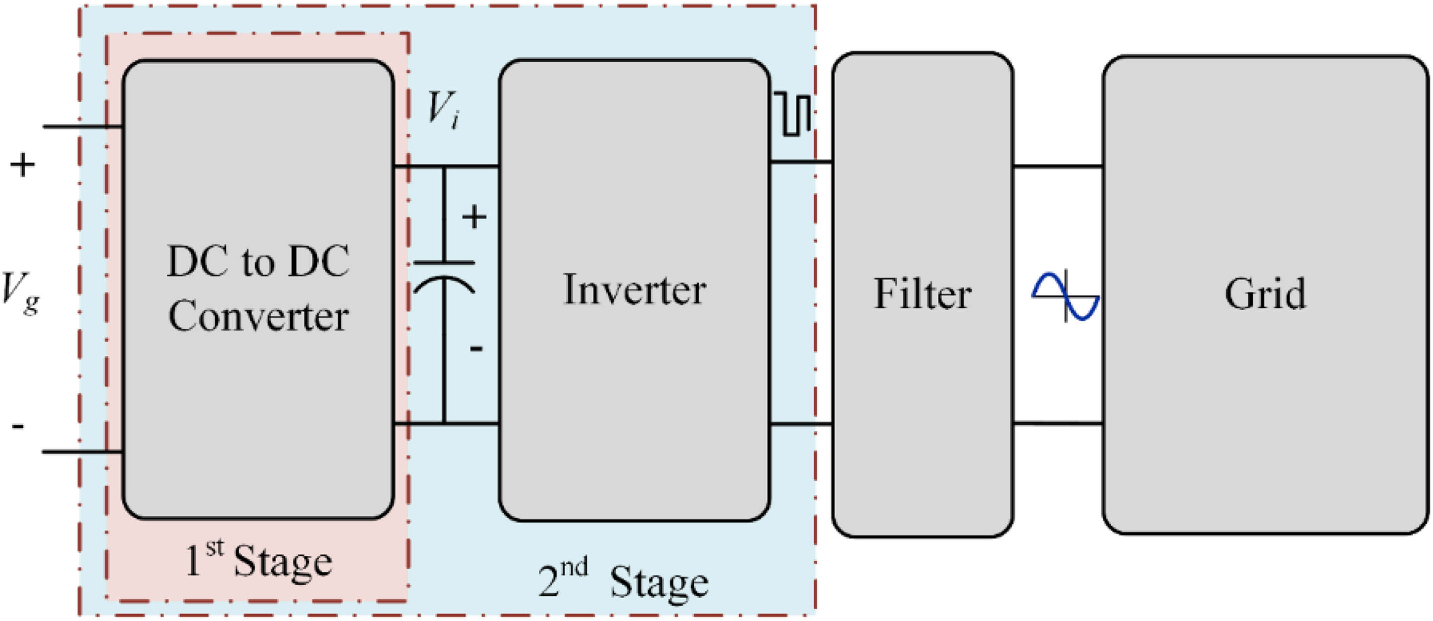
Overall, this article makes an important contribution to the development of solar energy technology and grid-connected PV systems through optimal SEPIC control. Figure 1 shows the schematic of the entire system of the proposed design, such as the PV array, SEPIC, ICA-optimized control loops, microinverter, and the grid connection. This is a view of overview of the operational flow plan and control architecture that has been the subject of discussion in this article.
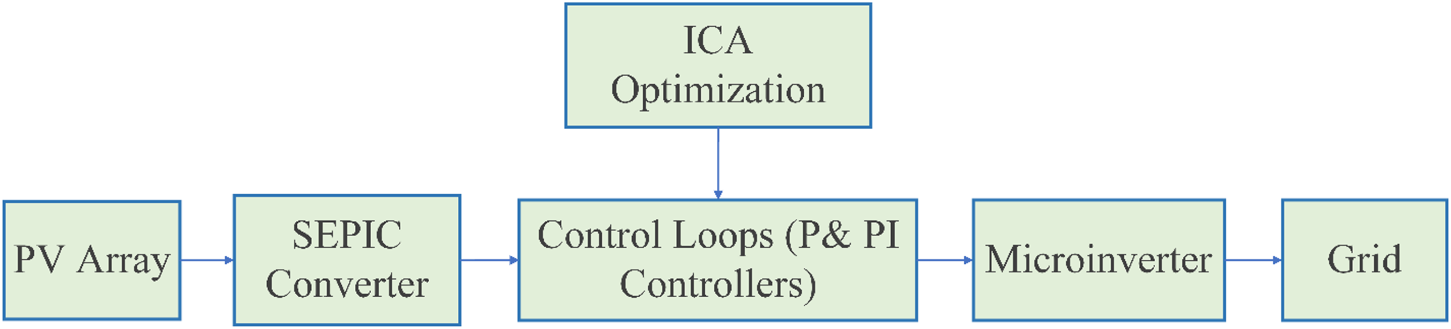
Overall block diagram of the proposed ICA-optimized SEPIC–microinverter system for grid-connected PV applications. ICA: imperialist competitive algorithm; SEPIC: single-ended primary inductor converter; PV: photovoltaic.
The rest of this article is organized as follows: the second section presents PV inverter topologies and SEPIC integration. The third section presents the system studied. The fourth section presents the results and discussion. Finally, the fifth section concludes the article.
PVv inverter topologies and SEPIC integration
Inverter architectures and control requirements
The device that converts DC produced by PV panels into AC for connection to a grid is called an inverter (Nadweh et al., 2020b). VSI, as shown in Figure 2(a), is used to stabilize the output voltage, while CSI, as shown in Figure 2(b), controls the current output (Nadweh et al., 2020c). This article focuses on a specific type of power electronic converter designed for use with current sourcing devices like a PV array to feed AC output into an electric grid from a DC input. A DC inductor (Ld) is required to smooth out input current ripples from the source. The full H-bridge switching circuit, including switches S1, S2, S3, S4, and their body diodes, forms the switching bridge. The control of the switching bridge is crucial for regulating the proper output AC current injection into the grid. A key distinction between a CSI and a VSI is the provision of a current output, which is beneficial for input sources that behave more like a current source, such as PV panels under varying irradiance conditions. This feature enhances power flow management and grid stability.
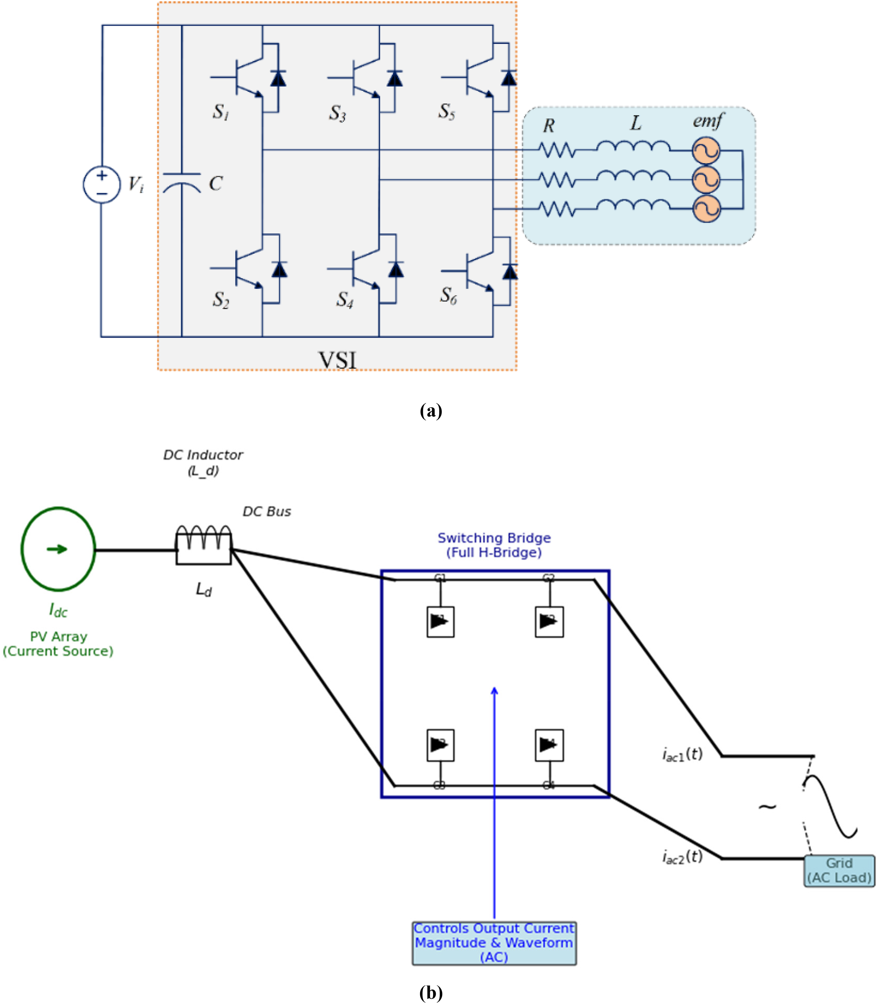
General installation of inverters (a) VSI, (b) CSI. CSI: current source inverter; VSI: voltage source inverter.
PV cells are considered natural current sources because their behavior is influenced by irradiance levels (Ibrahim et al., 2023a; Nadweh et al., 2020b, 2020c; Sinha et al., 2025b).
Single-stage inverters, as shown in Figure 3, are used when the DC voltage is near the grid requirements (Ibrahim et al., 2023b; Nadweh et al., 2019c). Direct DC–AC conversion allows for compact and cost-effective designs by eliminating intermediary stages. However, there is a limited range of voltage control.
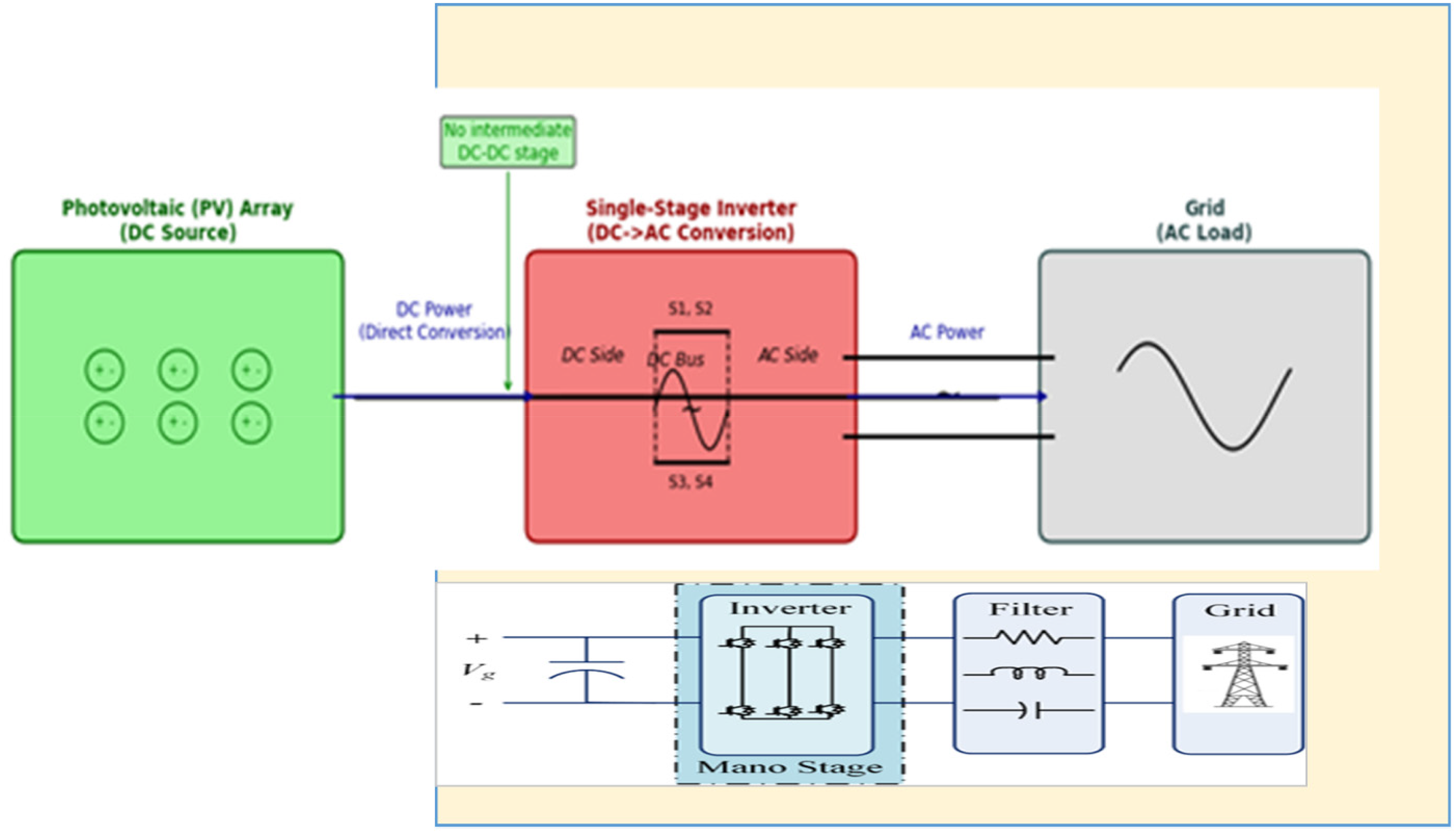
Configuration of the single-stage system.
The illustration depicts a single-stage grid-tied PV system that directly converts DC power from the PV array into AC power for the grid using a single inverter stage without a separate DC–DC converter. The essential components of this system include the PV array as the DC source, the single-stage inverter that performs both MPPT and DC-to-AC conversion, and the grid connection. The inverter regulates and synchronizes the power into the grid to ensure maximum energy transfer. This topology is more compact, cost-effective, and simpler compared to multistage systems but has a limited range for input voltage regulation. It is suitable when the DC voltage of the PV array is close to the grid voltage requirement. The direct conversion path is evident in this setup, which is typically more complex in two-stage systems. This configuration is commonly used in microinverter applications for residential or small-scale solar projects due to its ease of operation and fewer components.
The ZSI in Figure 4 overcomes traditional limitations with the assistance of a special impedance network (Subhani et al., 2021). Shoot-through states are employed as a means to boost voltage without the need for additional components (Elmorshedy et al., 2023; Sabarish and Kumar, 2024). This topology finds practical applications in renewable energy systems.
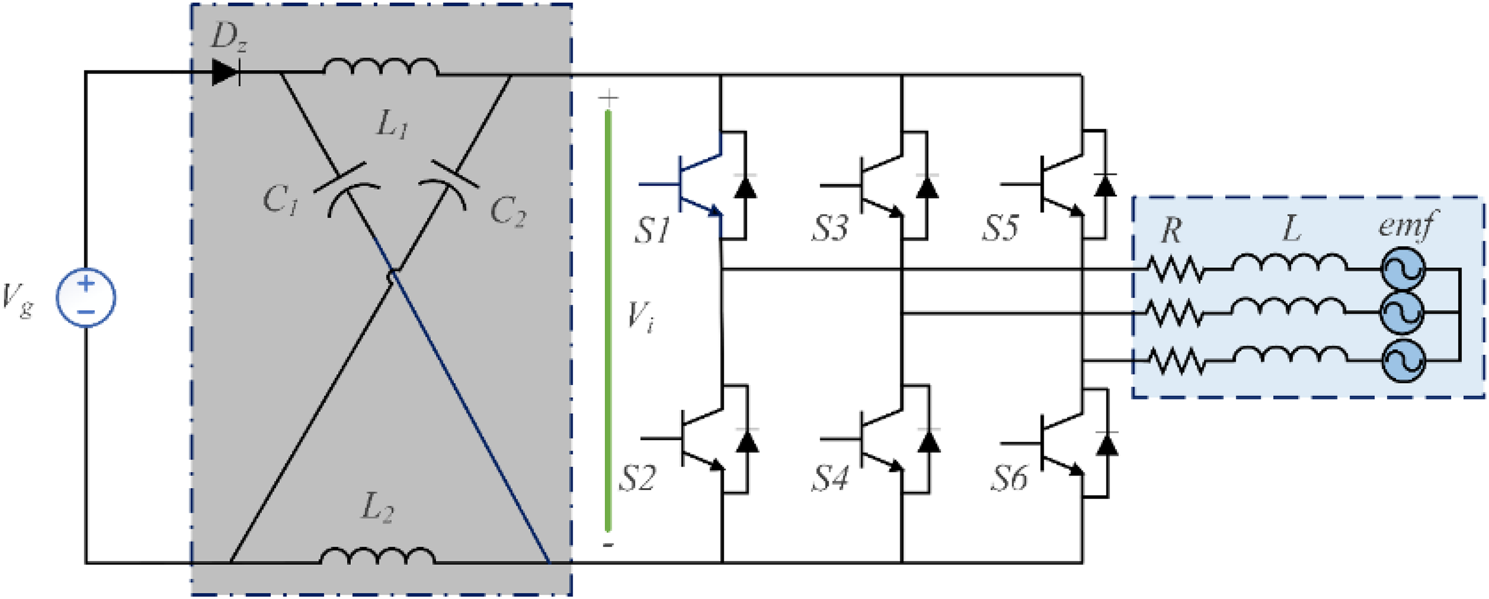
ZSI configuration. ZSI: Z-source inverter.
Two-stage inverters, Figure 5, incorporate a DC–DC conversion step before inversion, enabling a wider range of input voltage regulation and enhanced power quality (Mumtaz et al., 2021). These inverters have a more complex structure, which makes them relatively expensive, but they are commonly utilized in commercial applications that require high system performance.
General structure of two-stage inverters.
Transformer-integrated and string inverters are also used when there is a specific voltage-matching requirement (Raveendhra et al., 2023; Shabbeer Basha et al., 2024). The selection is based on the system size, cost, and performance considerations.
SEPIC–microinverter integration
Microinverters convert DC electricity generated by a separate PV module into AC electricity (Cheng et al., 2021). The working units are independent to make MPPT at the panel level and enhance system performance when partially shaded (Cheng et al., 2021). The modular structure is easy to install and maintain, and will make the system safer since there will be no high-voltage DC cabling (Nadweh et al., 2025). The device to be used is SEPIC, which is a flexible voltage converter with the scarce ability of firmly performing step-up and step-down conversion (Tarzamni et al., 2024). Figure 6 depicts the topology that has only a single active switch, two inductors (
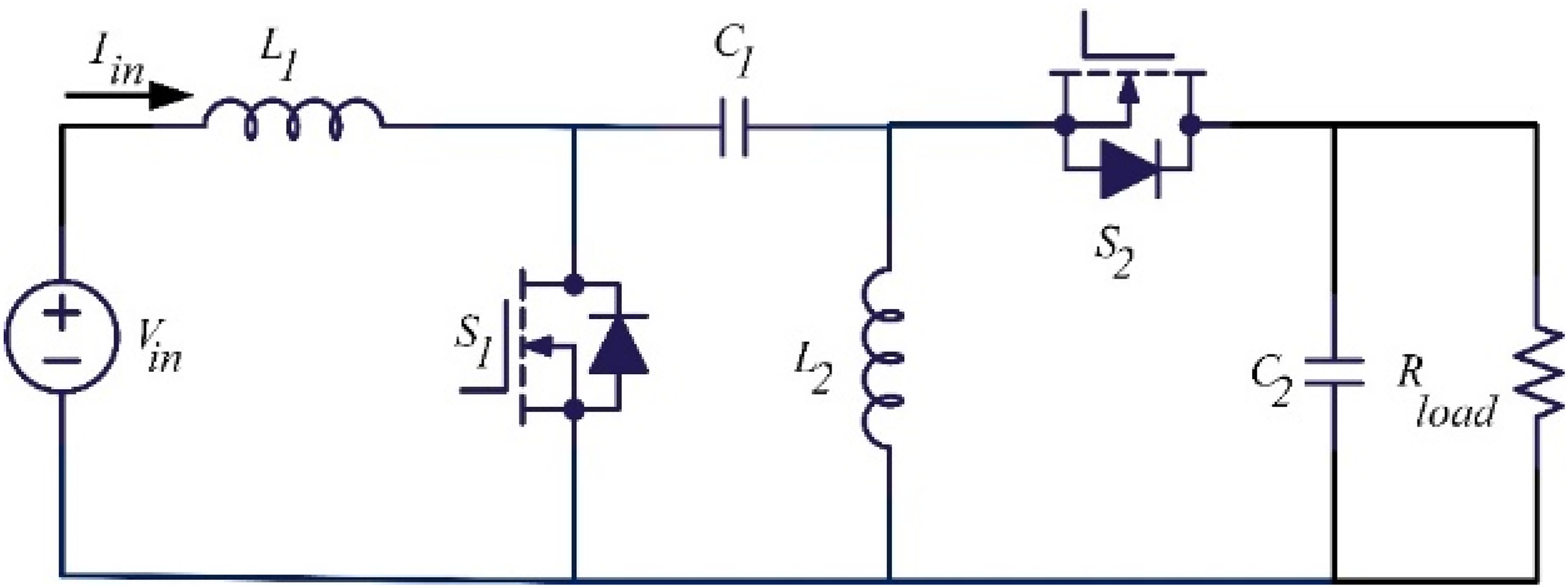
SEPIC operation in CCM. CCM: continuous conduction mode; SEPIC: single-ended primary inductor converter.
SEPIC, called continuous conduction mode converters, use a pair of complementary switches (
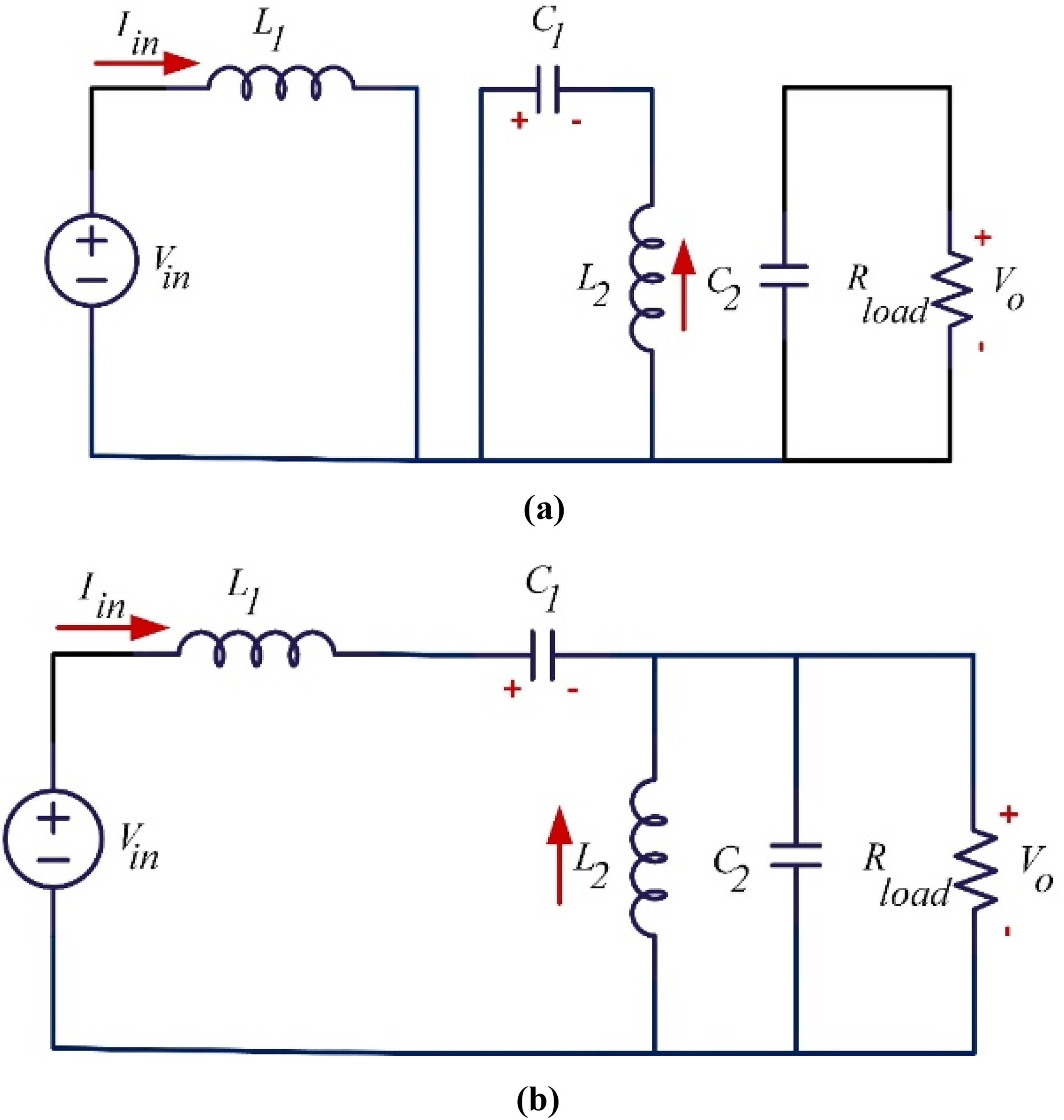
Operation mode of SEPIC: (a) first mode switches on and (b) second mode switches off. SEPIC: single-ended primary inductor converter.
SEPIC control circuits
The voltage and current sensors are utilized in a closed-loop connection to ensure a stable output voltage in SEPIC control (Gui et al., 2021). Several advanced control methods are employed to maximize performance, including:
Pulse width modulation (PWM): Universally effective in terms of variable voltage control accuracy and adaptability to power systems (Gui et al., 2021). Constant on-time/ off-time: This method provides a quick response to load changes, although it may reduce stability under certain circumstances (Thangam and Vel, 2023). Voltage/current mode control: Utilizes a combination of two-loop regulation to protect against voltage/current variations (Gao et al., 2022). Peak current mode control: Offers highly effective overload protection, simple implementation, and good noise immunity (Jalal and Habeeb, 2023). Variable frequency control: Achieves high efficiency at light loads but requires complex frequency adjustment (Hadi et al., 2024a).
The choice of control techniques depends on the specific system requirements, with PWM being particularly suitable for grid-connected PV systems due to its moderate accuracy and stability (Gui et al., 2021). The controller's switching parameters are adaptively adjusted to ensure optimal operation under varying conditions.
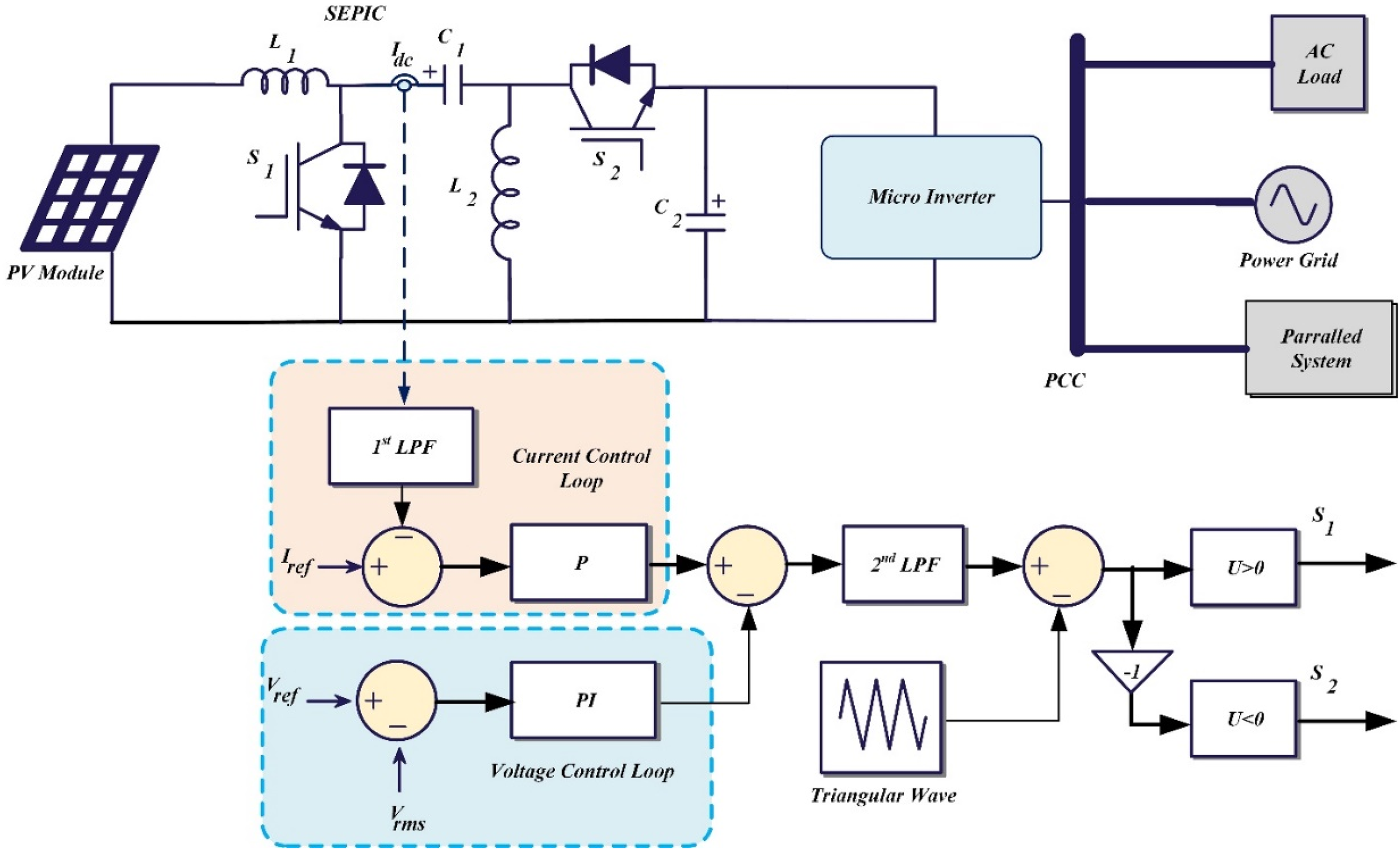
The proposed system
The system under study includes PV panels, a PV microinverter, and SEPIC. The conventional PV system is simulated in a MATLAB/Simulink environment before and after using a SEPIC to demonstrate its effect on system stability. An illustrative diagram of the system with the SEPIC is shown in Figure 8. The design parameters are further divided into three tables to allow clarity of the parameters as follows: Table 1, power electronics components; Table 2, ICA algorithm setup; and Table 3, controller constraints. Every table contains reference standards or optimization rationalization.
The studied system.
SEPIC parameters with design justifications.
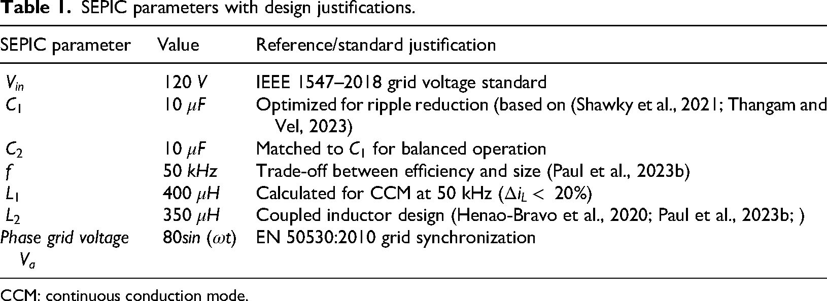
CCM: continuous conduction mode.
ICA algorithm configuration with optimization basis.
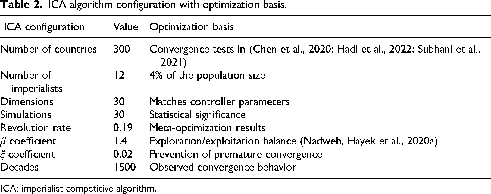
ICA: imperialist competitive algorithm.
ICA control parameters and constraints.
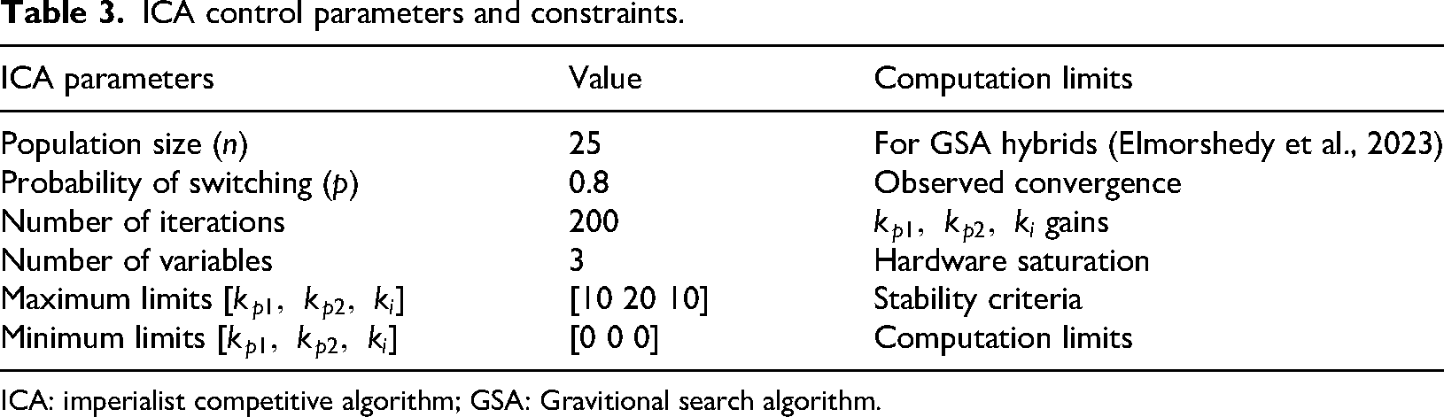
ICA: imperialist competitive algorithm; GSA: Gravitional search algorithm.
The electronic switches in the SEPIC are managed by a PWM control scheme for precise voltage regulation. The strategy involves adjusting the pulse width to regulate voltage and power. Two control loops are implemented in this scheme, one for voltage control and the other for current control. The ICA algorithm is used to optimize the controller constants in both loops, with a P controller for current error reduction and a PI controller for voltage error reduction, in addition to fine-tuning controller parameters to improve system performance. Based on the foraging habits of colonizing animals, ICA treats each colony as a potential solution set. The benefits of this method include improved system performance under varying conditions, flexibility to adapt to changes, and ease of implementation. The process of using ICA involves defining the objective function, initializing the algorithm, evaluating system performance, adjusting the PID constants, and repeating until the optimal constants are achieved.
The algorithm aims to improve the power quality on the grid side by improving the grid voltage (
Each comma is calculated based on the values you have, such as
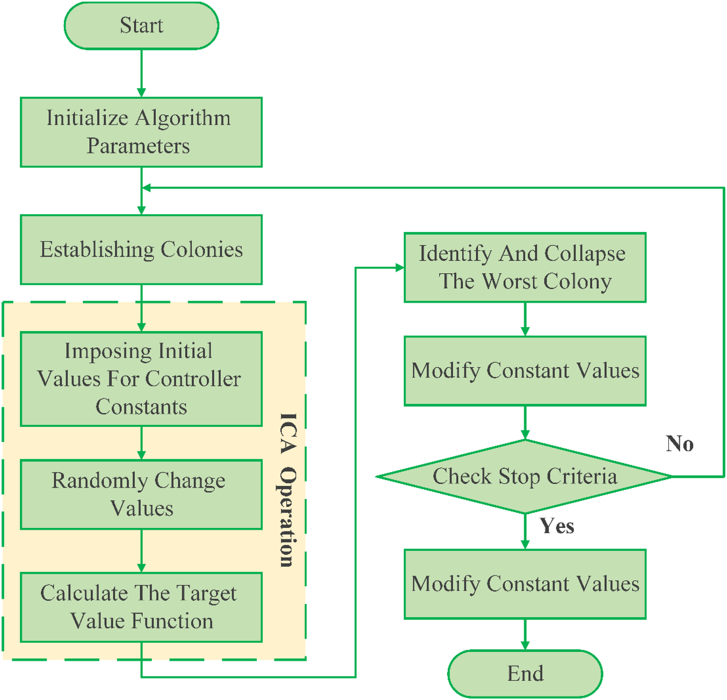
The flowchart of the studied system.
Results and discussions
Figure 10 shows the grid voltage response when there is a sudden load change at t = 1 s. The conventional system (without SEPIC) exhibited significant instability, with high variance (∼15 V peak-to-peak) and an overshoot of almost 20%. This results in low dynamic stability, leading to power quality issues in the grid. However, in the case of ICA-optimized SEPIC, the system maintains smooth voltage regulation with very low oscillation (∼3 V peak-to-peak) and no overshoot. This excellent voltage regulation is achieved through optimized PWM control, which quickly adjusts the duty cycle to attenuate disturbances.
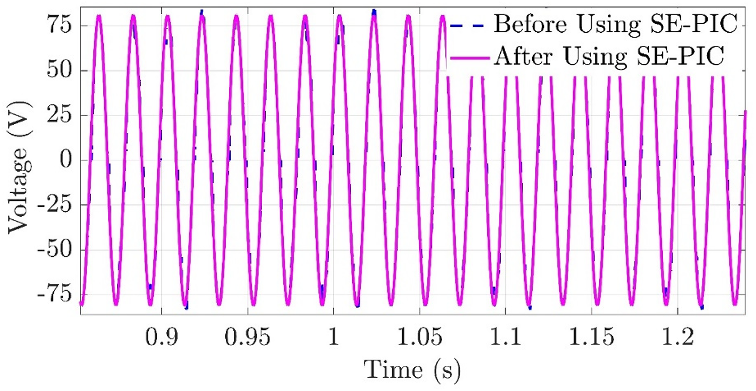
Grid voltage at load change in the conventional case and in the case of using SEPIC. SEPIC: single-ended primary inductor converter.
Figure 11 also illustrates the grid current responses, with traditional systems showing high current peaks during slow, oscillatory settling processes. The current response in the proposed system exhibits a sharp peak followed by a smooth, rapid settling into a new steady state. This high level of control helps to prevent current spikes, reduce stress on components, and improve the system's lifespan. The settling time for current exceeds 100 ms in the conventional system but is below 20 ms in the proposed system.
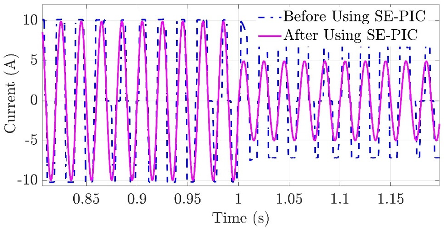
Grid current at load change in the conventional case and in the case of using SEPIC. SEPIC: single-ended primary inductor converter.
Figure 12, illustrates how the output voltage of the PV array remains stable when using the SEPIC converter, despite fluctuations in the input voltage caused by varying operating conditions such as shading. The performance of the SEPIC converter is analyzed with increased and decreased input steps from 24 to 29 V at t = 0.1 s (representing a 20.8% change in input voltage at t = 0.1 s). The output voltage is maintained at a reference value of 28 V, with catastrophic current limiting if it were to fall below 28 V. The system quickly rejects the input disturbance within 2 ms without any overshoot, demonstrating its transient performance. The converter maintains a conversion ratio of around 1.17 (28 V/24 V), showcasing its inherent buck-boost functionality. The output voltage ripple is below 2% under both static and dynamic modes, meeting the acceptable limits for grid-connected applications (e.g. IEEE 1547 standard). These results indicate that the PV panel can extract maximum power even under partial shading and rapidly changing weather conditions.
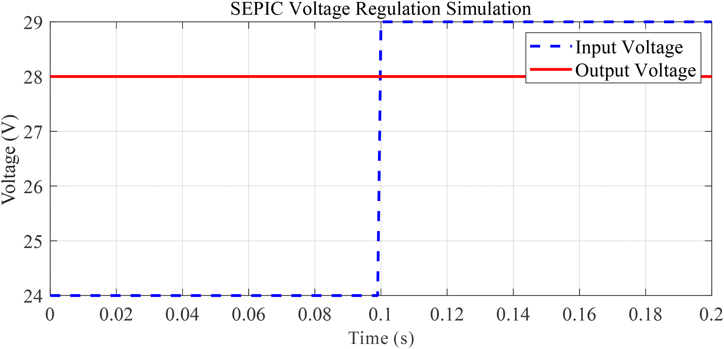
Output voltage stability when input voltage changes.
The buck-boost ability of the topology has been verified, as it is insensitive to changes in input. These performances demonstrate good results that can be applied in applications requiring a wide voltage input range.
This research quantitatively compares the performance of the proposed ICA-optimized PWM control against other common control strategies for SEPIC converters. A comprehensive feature-based comparison is provided in Table 4, while quantitative performance metrics are discussed in the following examination in Table 5. A detailed comparison of efficiency, response time, overload protection, interference, complexity, cost, advantages, disadvantages, switching frequency, and magnetic compatibility among the control methods used in the system is presented in Table 4.
The efficiency range for each control plan is shown in Figure 13, where the methods of PWM and Voltage/Current Control peak in efficiency (up to 92%–95%), while the proposed method, aided by real-time parameter tuning from the ICA, shows efficiency values above 90% over a wide range of loads. Although variable frequency control is efficient at light loads, it has slow response times (Figure 14), making it unsuitable for rapidly changing PV applications.
A comprehensive comparison of five control methods used to control the operation of switches in SEPIC.
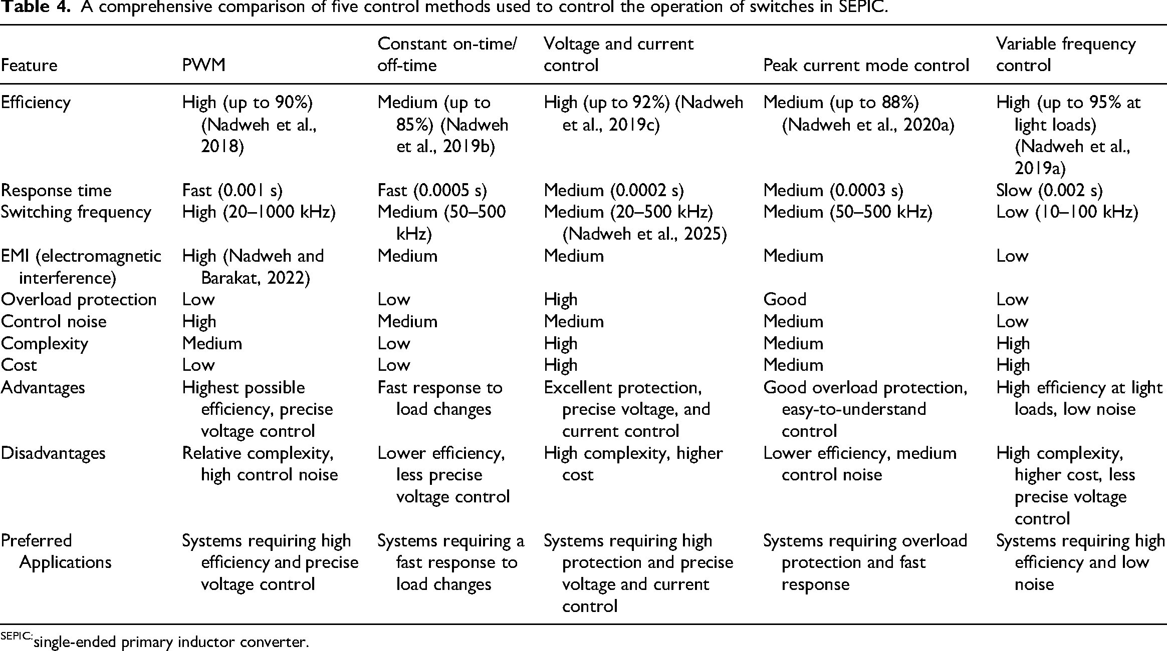
single-ended primary inductor converter.
Control strategies performance comparison.
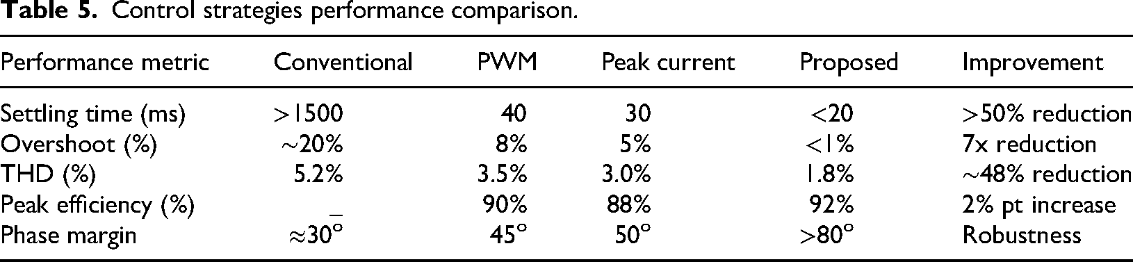
Table 5 shows the direct quantitative measurements of these important KPIs, which are the most important areas where ICA optimization improves transient responsiveness and power quality metrics, especially the KPI: Gain of PI.
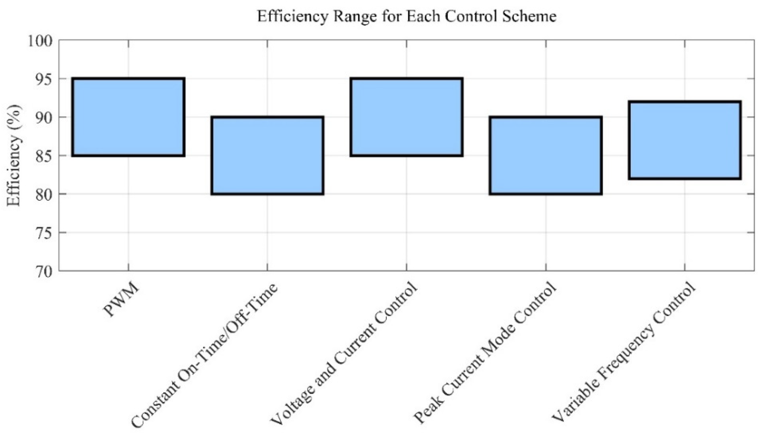
Efficiency of the control schemes used.
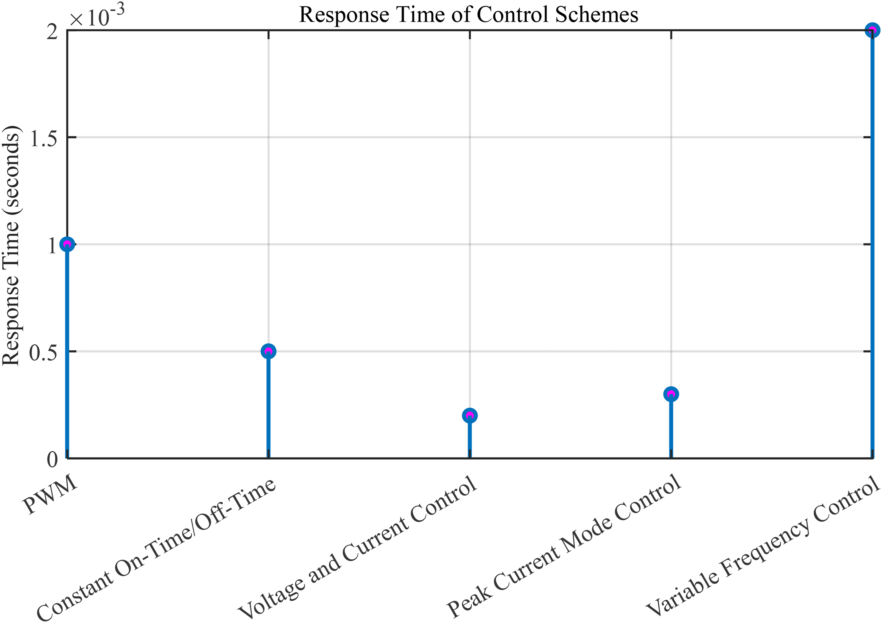
Response time of control schemes.
All the methods maintain their baseline efficiency above 80%, but constant on-time/off-time and peak current mode control have a 5% lower maximum efficiency (90%) than PWM. This example of variable frequency control illustrates the existence of a distinctive window of efficiency between 82% and 92%, which implies a trade-off between dynamic response and energy savings. These readings are acquired when closed-down load proportions are at standardized loads (50%–75% rated capacity).
Analytical evaluation of Table 5 and discussions are as below.
Transient response: The ICA-optimized control decreases settling time by more than half when compared with fixed-parameter PWM and reduces overshoot by an order of magnitude. Hence, power smoother, stable transients.
Power quality: THD of the output voltage, which is important for grid fitness, dropped to 1.8% with this technique, a significant 48% improvement over conventional PWM and below the 5% maximum defined in several standards (e.g. IEEE 519). Most of this decrease can be attributed to the optimization of the controller parameters by ICA to minimize harmonic generation.
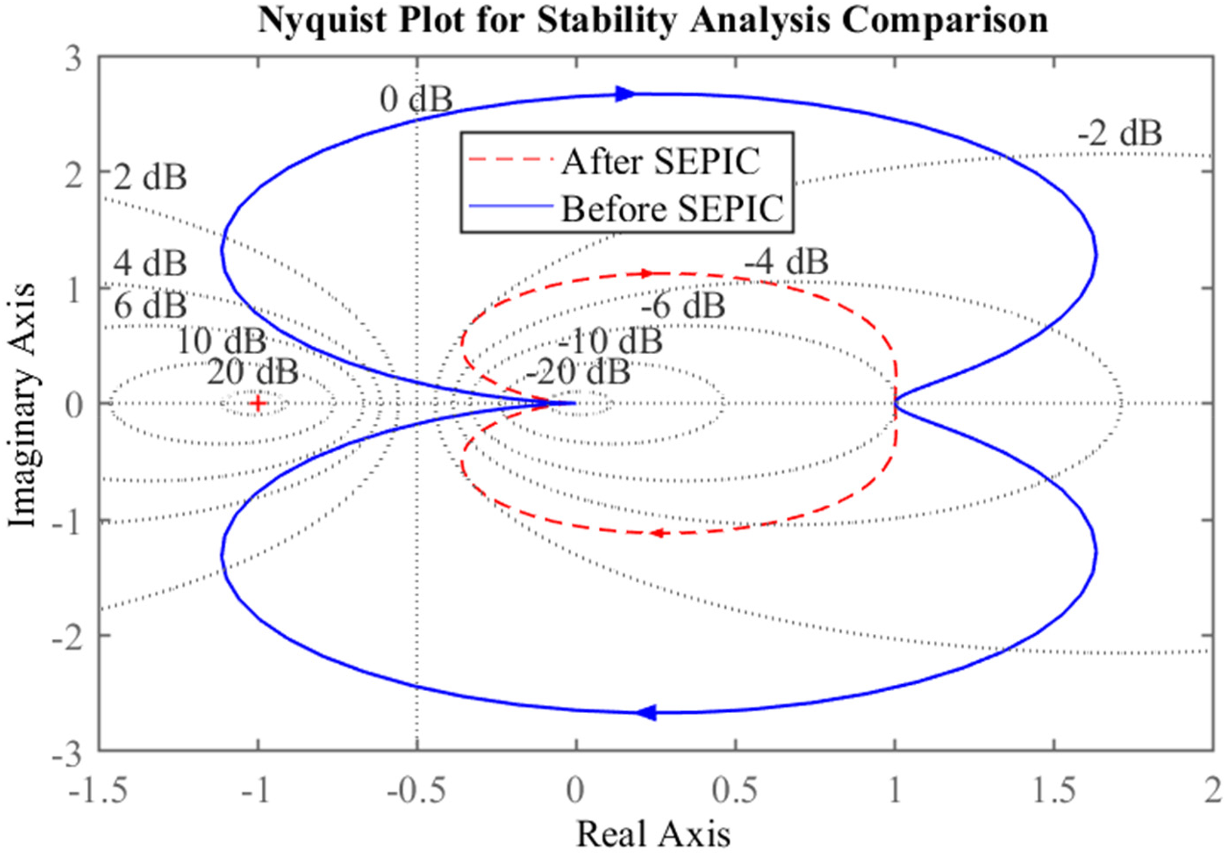
Stability: The Nyquist plot illustrated in Figure 15 enhances our confidence in the proposed robustness of the system. The phase margin has increased and remains above the critical threshold of 80 degrees following compensation, in contrast to the 45 degrees observed in the fixed-parameter scenario. A greater stability margin ensures dependable operation over a significantly broader range of grid impedances and conditions, thereby offering enhanced resilience to unforeseen disturbances.
Nyquist plot to determine system stability.
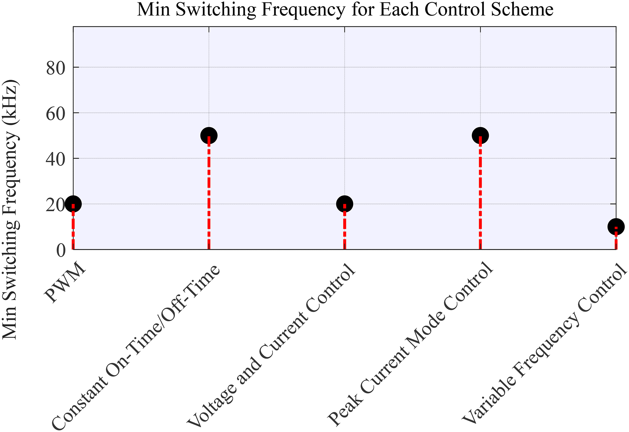
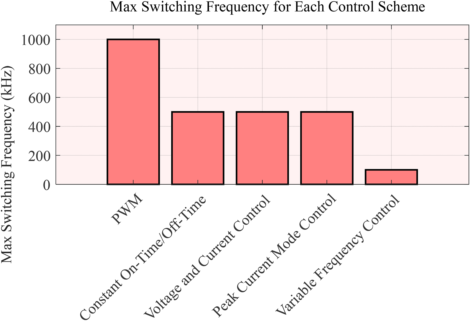
Figures 16 and 17 demonstrate that the PWM control scheme has the highest switching frequency, making it versatile for a wide range of applications. The lower operating frequency ranges from 10 kHz (variable frequency control) to 50 kHz (constant on-time/off-time and peak current mode control). PWM and voltage/current control only require 20 kHz for regulation, indicating better stability at low loads. This 5:1 difference highlights the design constraints for energy-sensitive applications. The measurements are taken at an ambient temperature of 25°C, and all values are verified at this temperature. In comparison to other techniques, PWM has a maximum switching frequency of 1000 kHz, while alternative methods can achieve 500 kHz or less. Variable frequency control has a critical upper limit of 100 kHz, showcasing its suitability for low-noise environments. The significant performance gap of 10 to 1 between PWM and variable frequency control underscores the fundamental limitations of the topologies. These limits are defined as a 90% duty cycle and <1% ripple current.
Minimum switching frequency for each control plan.
Maximum switching frequency for each control plan.
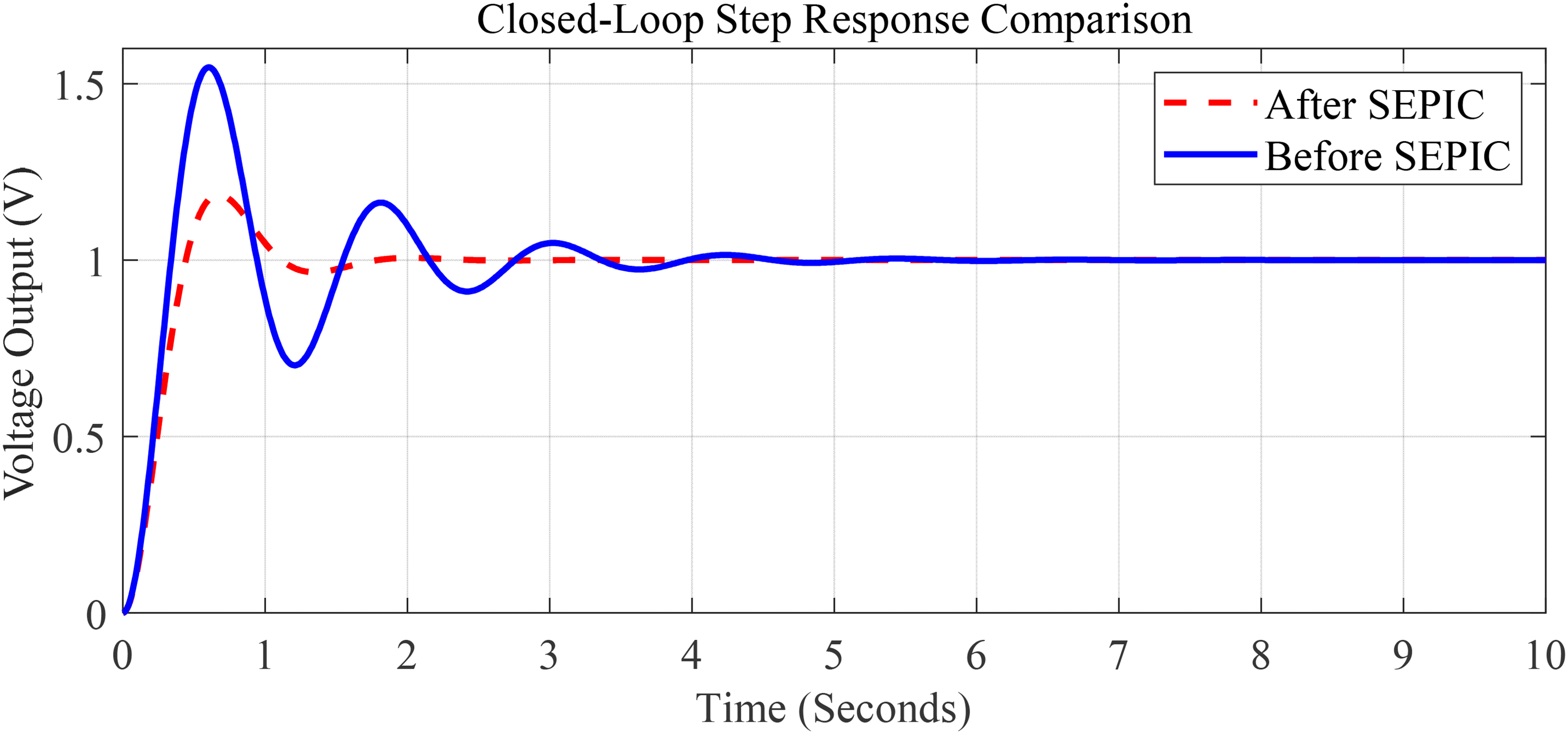
The transfer function of the original system (equation 2) is a simple integrator, which explains the slow response and high overshoot, as shown in Figure 18. After integrating the SEPIC with ICA-optimized control, the new transfer function (equation 3) represents a first-order system that has been well-damped. The transfer function of the conventional system is given by (equation 2):
Single-step response for the conventional system and the system with SEPIC. SEPIC: single-ended primary inductor converter.

The transfer function of the system after adding SEPIC according to equation (3).
The performance of the conventional system, as shown in Figure 18, demonstrates a settling time of 1.5 s with an overshoot of 20%. In contrast, the ICA-optimized SEPIC system has a settling time of approximately 0.6 s, which is a 60% reduction from the conventional system, and it has zero overshoot. Additionally, the damping ratio has increased from 0.19 in the conventional system to 0.47 in the ICA-optimized model, indicating better oscillation suppression.
In summary, Figure 18 visually illustrates the significant improvement in settling time by 60% (from 1.5 to 0.6 s) and the elimination of overshoot. The increase in damping ratio from 0.19 to 0.47 has shifted the system from underdamped and oscillatory to approaching critical damping, resulting in a faster and smoother response.
The impact of various control strategies can be seen in the improvement of performance efficiency, the provision of quality power for proper function, the reduction of total harmonic distortion, the minimization of circuit losses, cost minimization, and consideration of setup costs.
The traditional system is analyzed with a Nyquist diagram, as shown in Figure 15, revealing the significant influence of SEPIC on system stability. More open stability margins are shown by Nyquist analysis, in which the phase margin is raised by 35 degrees following the compensation. The crossover frequency of the gain is moved up, being 2.1 to 4.7 rad/s, and the dynamic response is faster. The phase angle crosses −180 in the frequency range below the operating range, which proves absolute stability. The tests of these improvements are quantified in the usual 28 V test voltage used in the step response measurements. To ensure robust stability under overall operating conditions, the encirclement criterion of Nyquist is used. The compensated system does not have any right-half-plane poles.
Response times of five control schemes were compared quantitatively, with variable frequency control having the slowest response time (2 ms) and voltage/current control having the fastest response time (0.2 ms). Peak current mode control (0.3 ms) was found to be 40% faster than PWM (0.5 ms), while constant on-time/off-time control showed intermediate performance (0.5 ms). The values were obtained by averaging over 10,000 cycles with a measurement reproducibility of ±0.01 ms. These measurements were taken at an operating temperature of 300 K and 50% load conditions. The response time of PWM (1 ms) was also found to be 5 times slower than voltage/current control, highlighting a limitation of the basic architecture. These results provide valuable insights for high-speed power conversion systems requiring regulation in <1ms, as illustrated in Figure 14.
The findings reveal that the ICA-optimized control strategy for the SEPIC microinverter is the best in every evaluated criterion. Its notable achievement is the ability to simultaneously optimize two conflicting objectives: fast dynamic response (low Ts), excellent stability (high phase margin, no overshoot), and good power quality (low THD).
Direct comparisons in Table 5 and stability analyses conducted in Figures 15 and 187 provide compelling evidence that addresses the inadequacies mentioned in the introduction, particularly regarding transient behavior and distortion control. The proposed system not only fulfills its purpose effectively but also demonstrates robustness, making it suitable for real PV-grid sites worldwide where operating conditions are constantly changing.
Conclusions and recommendations
In this article, the use of the ICA is proposed to fine-tune the parameters of P&PI controllers for controlling electronic switches in SEPIC integrated with microinverters to improve the performance and stability in grid-connected PV systems. The system is simulated in MATLAB, and adjustments are made to the parameters of the P and PI controllers used in the PWM control strategy for SEPIC operation. Furthermore, a comparison is made between this control strategy and conventional ones, and the impact of integrating SEPIC into the conventional system is analyzed. The results indicate that the proposed system provides a successful means to increase the efficiency and reliability of grid-connected PV systems while improving grid power quality by refining voltage and current waveforms. This contributes to a greater reliance on renewable energy for a more sustainable future. It is recommended that the proposed system be implemented in real-world scenarios to more fully evaluate its performance. In addition, further research should be conducted to explore the impact of various factors on the system's performance, such as variations in solar radiation and temperature.
Proposing an ICA-optimized control strategy for an SEPIC-based microinverter was carried out in this study. Simulation results proved significant superiority over the conventional methods, including a transient response that was faster by more than 50%, eradication of voltage overshoot, and a 48% reduction in harmonic distortion. These aspects clearly illustrated the effectiveness of the strategy in enhancing stability and power quality in grid-connected photovoltaic systems.
Nonetheless, acknowledged as some of the most significant results, this study has a limitation that delineates clear paths for further exploration:
Computational load: It is crucial to examine the computational burden of the independent component analysis for real-time implementation. The subsequent research will primarily focus on deploying the controller on a digital signal processor or field programmable gate array chip to assess its practical applicability. Extended testing: A thorough investigation of fault ride-through capability necessitates an extensive analysis of the system's robustness under various grid fault conditions, including voltage sags, frequency variations, and so forth. Economic viability: The large-scale economic scalability of the proposed design must be corroborated by a cost-benefit analysis in relation to commercial alternatives.
Footnotes
List of abbreviations
Funding
The authors received no financial support for the research, authorship, and/or publication of this article.
Declaration of conflicting interests
The authors declared no potential conflicts of interest with respect to the research, authorship, and/or publication of this article.
Data availability statement
All relevant data are within the article.