
Abstract
In this paper, a hybrid, comprising of solar-PV and wind energy sources, grid-connected system with nine-switch converter (NSC) instead of a back-to-back (BtB) converter (comprising 12 switches) is proposed and a control scheme is also proposed for NSC. NSC is the potential substitute for the current BtB converter, which uses 12 switches. The NSC uses nine switches, that is, three less active switches than BtB converter therefore the system efficiency is increased by lowering component costs, counts of components, and switching losses. Vector control concept is considered to design the proposed control scheme for NSC to provide both supply power generation to the utility grid at unity power factor and variable speed constant frequency operation under fluctuating wind velocity and solar irradiance. In addition, 120° discontinuous modulation concept is integrated with the control scheme of NSC for reducing the switching losses of the system. Moreover, maximum power point trackers are used for capturing maximum power from wind and solar-PV, and blade pitch angle algorithm is also considered to restrict the generation from wind to its rated power level while speed is more than its rated level. The proposed system along with its control scheme is implemented in OPAL-RT lab to investigate its performance thoroughly under real-life scenarios (i) constant solar irradiance and variable wind velocity and (ii) variable solar irradiance and wind velocity. Results show the effectiveness of the proposed scheme on the system and it has been observed that the proposed scheme provides good dynamic responses in terms of less oscillation during transient, almost negligible (i.e. 0.0001 approx.) steady-state error etc. to the variation of input sources.
Keywords
Introduction
Renewable energy sources (RES) have plenty of advantages over conventional sources (Abdolrasol et al., 2021; Barik et al., 2021; Chauhan et al., 2021) and due to these reasons, RESs have been attaining substantial attention in the power sector for the last two decades. But, RESs-based systems have some noticeable issues like exceptionally change in the output characteristics of RESs since such types of sources mainly depend on the conditions of climate (Basu et al., 2022; Hussain et al., 2020; Ulutas et al., 2020). Power electronics converters play a key role in association with maximum power point tracking (MPPT) algorithms to extract the maximum energy safely from RESs (Aboudrar et al., 2019; Datta et al., 2019a). Such types of resource-based systems are (i) islanding and (ii) grid-connected (Sharma et al., 2019; Zeng et al., 2020). Later one is a reliable mode of the system since continuous power can be delivered by it even if there is any shortage of power due to climate change. Hybrid stand-alone systems have gained increased attention for the area where main grid is not available and far away from main urban area. Many wind-solar-based grid-connected and wind-solar-battery-based stand-alone system are reported in the literature by many authors (Al-Quraan and Al-Qaisi, 2021; Anusuya et al., 2023). However, there are many issues and challenges in both grid-connected and stand-alone-based hybrid systems that need to be addressed. A hybrid strategy was proposed for 15-level inverter-based grid-integrated solar PV system (Anusuya et al., 2023) to maximize energy conversion and fulfill the load demand. But, in this paper only solar-PV unit was considered and control scheme for proposed multilevel (15-level) inverter is complex. In Yavuzdeger and Ekinci (2023), solar panels mounted hybrid rotating energy system was proposed and manufactured using 3D-print technology to enhance the accuracy of output power estimation of the RES. But, MPPT converter topologies were not reported and also only solar-PV system was considered in this study. A permanent magnet synchronous generator (PMSG)-based wind turbine (WT) is commonly used in RESs-based hybrid systems since it has some important merits over other WT generators (Karimi-Davijani, 2012).
A solar-PV and battery-based DC microgrid was proposed in Yadav and Singh (2024) with dual series virtual impedance based fuzzy controller to enhance the stability of the system. But inverter topology was not considered and wind source is also not considered. A hybrid isolated system (comprising solar-PV, battery, and fuel cell) was implemented to study the performance of the system but wind energy was not considered in this study and results were also not validated. A system was implemented only by using wind, that is, other renewable sources were not incorporated into the behavior of the system (Datta et al., 2019b; Datta et al., 2020; Datta et al., 2022b). An innovative method for progressive alpha modelling with four parameters was proposed to improve the power system reliability with the insertion of WT (Akhtar et al., 2022) but only wind was considered in this study. Owing to good performance and having independent control capability, vector control (VC) techniques were used mostly in electric drive systems to attain variable speed constant frequency (VSCF) operation (Datta et al., 2019b; Datta et al., 2022b). Magnetic flux and voltage-oriented VC techniques were reported in Akhtar et al. (2022) and used in WT systems. In Aboudrar et al. (2019), the solar-wind hybrid system, grid-connected, was reported to study its performance at below rated and rated wind speed. But, to restrict power generation to its rated value when the velocity of wind is more than rated, no technique was reported in Aboudrar et al. (2019). A standalone hybrid solar-PV-wind micro-grid system was reported in Al-Quraan and Al-Qaisi (2021), but 12-switch-based inverter was used and also pitch control concept was not incorporated to restrict power generation within the rated power limit. In Hamid et al. (2022), a grid-connected hybrid system, comprising the solar-PV unit and wind unit with back-to-back (BtB) converter, was only implemented in MATLAB and the responses were studied at varying wind velocities and the blade angle algorithm was also incorporated. In Antalem and Bhattacharya (2022), multiple RESs grid-interactive decentralized control of hybrid DC/AC microgrid was considered to supply efficient power to the grid by regulating power flow among all units. But, the current in transient period is very high just after clearance of the fault. In Datta et al. (2022a) and Chankaya et al. (2021) a hybrid isolated system (comprising solar-PV, battery, and fuel cell) was implemented to study the performance of the system, but wind energy was not considered in this study and results were also not validated. In Kumar et al. (2019b) and Sumathi and Umasankar (2023), a hybrid isolated system (comprising solar-PV, battery, wind and fuel cell) was implemented to study the performance of the system, but control schemes are missing. In Harisha and Jayasankar (2023), only load frequency control was studied in this power system with integration of wind farm.
Nowadays, a reduction in the number of active power switches and their complemented driver circuitries are also of attention for reducing the overall costs and switching losses of the hybrid system. Some researchers have shown extreme attention in nine-switch converter (NSC) as a substitute for the BtB voltage source converter (VSC) as the number of switches, as well as the associated gating drivers, heat-sinks, protection circuits, and snubbers are reduced from 12 to 9. It has revealed good performance in the decoupling control of two 3-phase AC loads (Gulbudak et al., 2021; Kominami and Fujimoto 2007a; Liu et al., 2012; Liu et al., 2013b; Oka and Matsuse, 2007) and has been utilized as a power quality improvement device, named unified power quality conditioner (Liu et al., 2009), electrical machines (Kominami and Fujimoto, 2007a), hybrid electric vehicles (Dehghan et al., 2010), wind power systems (Wen et al., 2016), uninterruptible power supplies (UPS) (Kominami and Fujimoto, 2007b), hybrid distributed generation systems (Liu et al., 2013a), and photovoltaic systems (Loh et al., 2013; Soe et al., 2011).
The NSC has the benefit of reduced switch count compared to the BtB VSCs. In Lei et al. (2012) and Liu et al. (2007), it has been experimentally confirmed that NSC can supply power to two independent AC loads and works well at different frequencies (DF) as well as at common frequency (CF), thereby reducing the cost for manufacturing, component count, losses due to switching and improve system efficiency. Various modulation schemes have been reported (Gao et al., 2010; Lei et al., 2012; Ojo, 2004) for the operation of NSC in both CF and DF modes. The benefit of NSC lies in its auto-complementary tuning of the parallel and series converters under normal and sag circumstances. Under the normal operating condition, the parallel converter modulates to provide its maximum output whereas the series converter provides almost zero output. The value of the common DC capacitor of NSC is only 8% higher than that of the BtB converter and experimental results show that a load is very immune to 20% balance voltage sag (Hava et al., 1998). As far as the WT system is concerned, the application of NSC can also be used to enhance low voltage ride-through capability (Datta et al., 2022b). In Datta et al. (2022b) and Liu et al. (2020), NSC is used in a grid-connected doubly fed induction generator-based WT system to attain VSCF operation and experimental results are not reported in Datta et al. (2022b). A literature survey indicates that no application of NSC has been made to date in RESs-based hybrid systems.
In Singh et al. (2014), a real-time digital simulator, OPAL-RT lab, is used to implement the system for validating system responses. RT-lab completely incorporated with MATLAB/Simulink, offers bendable and accessible responses for the implemented systems. In Das et al. (2021) and Kumar et al. (2019a), a transfer functions-based micro-grid system is implemented in the OPAL-RT platform for validating the system responses. However, the RT simulation of a hybrid system (comprising a generator, static components, control scheme, etc.) using OPAL-RT is very limited; hence requiring investigation for achieving experimental validation.
From the above-mentioned survey, it has been noticed that many issues are still there in hybrid system, comprising of solar-PV and wind, grid-connected system like missing of co-ordinate control scheme, and current in transient period is very high. The number of active power electronics switches are more in existing solar-PV and wind based hybrid grid-connected system and hence, the overall costs and switching losses of the hybrid system is higher. In order to overcome these drawbacks, NSC-based grid-connected hybrid system is proposed in this paper and the main contributions in this paper are as follows:
RERs (solar-PV and wind)-based grid-connected hybrid system with NSC at DF level has been proposed to reduce the number of switching devices, switching losses, and cost of the system. A new control scheme is proposed for NSC to obtain VSCF operation at varying wind speeds. MPPT and pitch angle algorithms are additionally integrated to limit and capture power generation accordingly. An appropriate discontinuous modulation technique, that is, 120° modulation technique has been incorporated in the control scheme of NSC for reducing system switching losses by reducing commutation counts. It is implemented in the OPAL-RT digital lab platform to verify the performance of the proposed system under real-life scenarios (i) constant solar irradiance and variable wind velocity and (ii) variable solar irradiance and wind velocity.
Based on the objectives mentioned above, this paper has been prepared as given below: first, the detail of the hybrid system is illustrated; secondly, the detail of the proposed control scheme is presented; thirdly, the system responses and analysis of the results are investigated under various conditions; finally, the conclusion is drawn.
Description of the hybrid system
The NSC-based hybrid system is shown in Figure 1 and the system consists of solar-PV, unidirectional DC/DC converter, WT with PMSG, and NSC. NSC has two sets of independent 3-phase input/output systems as shown in Figure 1; one set is connected to the stator of PMSG to deal with power (active and reactive) flow, generator rotor speed, etc. at variable wind speed and the second set is joined to the grid via interfacing inductors to realize the flow of power between grid and PMSG at unity power factor (UPF) by incorporating VC techniques.
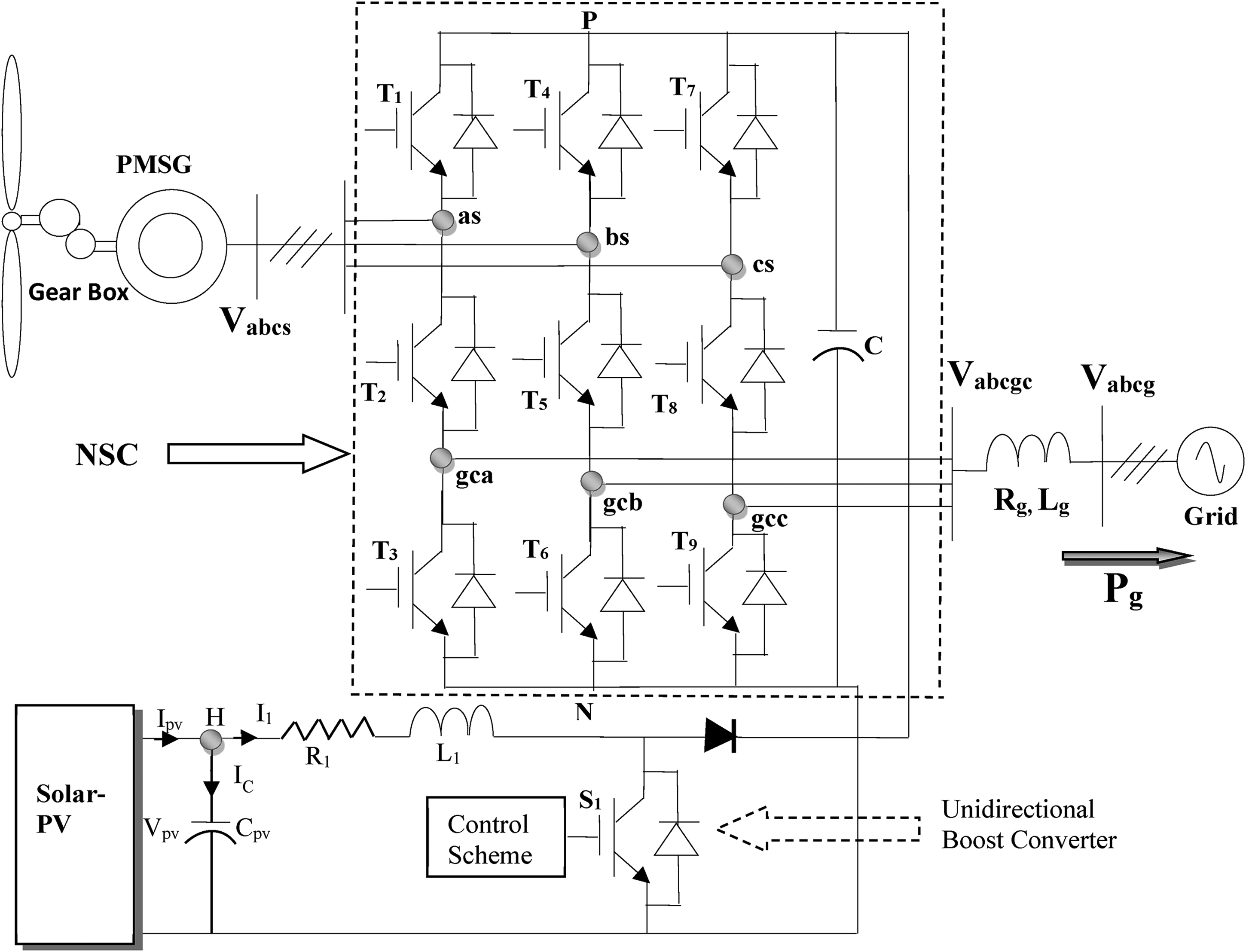
NSC-based grid-connected hybrid (solar and wind) system.
Wind turbine unit
A wind energy system is intended to have a turbine connected to a PMSG whose output is connected to a power electronic converter for achieving the VSCF operation under variable wind velocity. Mechanical power (PT) acquired from the turbine of wind at a particular wind velocity (Vω) can be assessed by using equation (1) (Datta et al., 2019a):

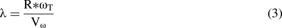
The coefficient of power and ratio of the tip speed can be calculated using equations (2) and (3) respectively (Datta et al., 2019a).

The PMSG voltage equations, in the reference frame of synchronously rotating, are provided as follows (Datta et al., 2019a):


Electrical torque can be written as


Solar energy system
The solar energy system includes a PV array in which output is connected to a unidirectional boost DC-DC converter (illustrated in Figure 1), to increase the magnitude of the input voltage by adjusting the power output of PV. Equations (11) and (12) are obtained by applying KCL and KVL at node “H” as shown in Figure 1. Figure 2 shows the control scheme of solar-PV unit. Solar irradiance input is led through MPPT (MPPT method is explained in Datta et al. (2020) and Datta et al. (2022a) briefly) to compute the output PV reference voltage (Vpv*) and current (Ipv*) corresponding to its maximum power. The difference between the reference and actual voltage output of solar-PV is further processed using a voltage PI controller for obtaining a current reference (IC*) which is flowing through the capacitor (Cpv). Equation (11) is used to compute current I1* where Ic* is subtracted from Ipv*. Current error computes from reference and actual currents (I1* and I1) and then process through the current PI controller to generate regulated voltage. Duty ratio is obtained using DC-link voltage (Vdc) and regulated voltage and thereafter trigger signal is obtained using pulse generator for controlling unidirectional boost converter (Datta et al., 2020), as shown in Figure 2, of solar PV unit.


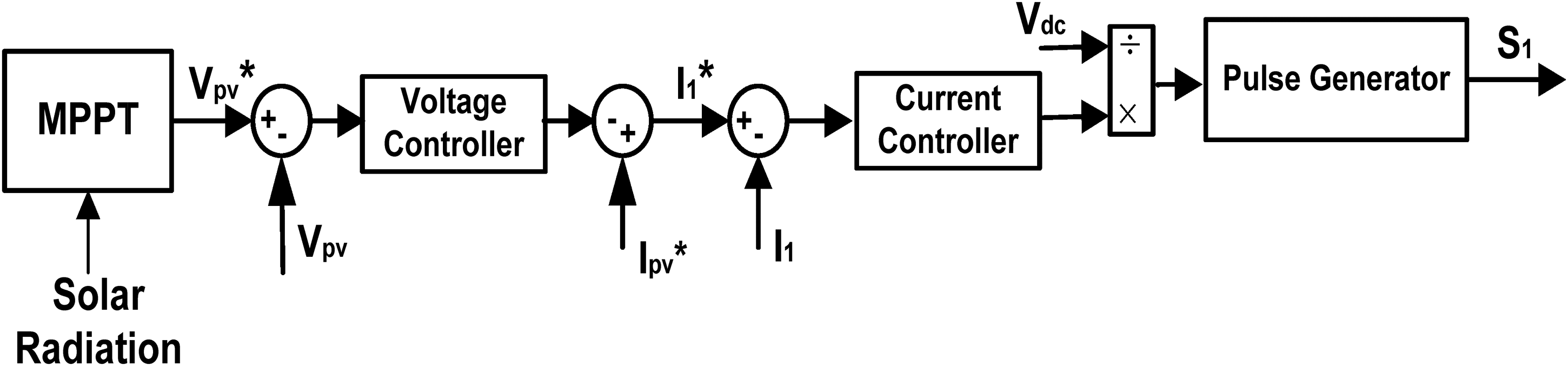
Control strategy for boost converter of the solar-PV unit.
Nine switch converter
Figure 1 illustrates the NSC which is associated with three IGBT switches in each leg, assigning a total of nine switches for all 3-phases. For each leg, the middle switch is common to both rectifier and inverter operations. Comparing the BtB, 12-switch converter and conventional matrix converter, the arrangement lowers the switch count by 33% and 50% respectively (Liu et al., 2013b). The upper and lower terminals per phase of NSC can connect to upper DC rail-P (Vdc) and lower DC rail-N (0 V). The limitation of the NSC is that the connection of the upper terminal to N and the lower terminal to P is not possible because such an arrangement would create a short circuit in the DC-link capacitor. This drawback can be solved by the introduction of two separate modulating reference signals (upper and lower) in each leg of the phase so the upper terminal reference is always higher than the reference of lower terminal (Liu et al., 2013b).
The triggering signals for lower and upper switches of NSC are obtained by considering the triangular carrier signal with their respective modulating reference signals. For the middle switches, the triggering signal is produced through logical X-OR gate signals of upper and lower switches of NSC. The NSC may be conducted either in CF mode or in DF mode. The CF model applies to the converters where the output frequencies are the same as that of the utility supply. And also the frequency remains constant even though converter output voltages are variable. When the magnitude and frequency of the converter output voltages are adjustable then DF mode is suitable. The required pulse signal to operate NSC can be achieved by considering the following conditions:
T1= ON, when the upper reference signal is higher than the triangular carrier signal, else OFF.
T3= ON, when the lower reference signal is lesser than the triangular carrier signal else OFF.

NSC modulation method
For NSC, the control of output voltage is realized through three switches present in each leg (Liu et al., 2013b). The middle switch in each individual leg is shared by both the rectifier and the inverter and a switching state for 12-switch BtB converter is also not present in NSC. This indicates that at any point in time the converter leg voltage VgcaN is always lower than leg voltage VasN. This is the main drawback in designing the switching scheme of NSC. Therefore, it is not possible to achieve the optimal waveform. With the advance in technology, modern power conversion methods have reduced harmonic or spectral distortions (Datta et al., 2022b). The main aim of modulation of NSC should be the minimization of switching losses rather than spectral gain. To consider instant modulation option would be classical discontinuous techniques, like the 60° and 30°discontinuous modulation (DM) techniques as reported in Lei et al. (2012). These discontinuous (60° and 30°) schemes are unsuitable for NSC (Ojo, 2004) since output terminals both upper and lower DC-rail clamping per set are required. And also sometimes creates a signal of the upper reference to drop below the signal of the lower reference. NSC accepts only upper dc-rail clamping for its upper terminal phases and lower dc-rail clamping for its lower terminal phases, which can be accomplished by a 120° DM scheme. The CF and DF modes of 120° DM schemes are briefly provided in Lei et al. (2012) and Liu et al. (2007). The research work on this paper is based on DF mode, so this mode is briefly explained in the subsequent section.
Different frequency mode
To operate in DF mode the set of two terminals of NSC should be connected to loads or sources. Sometimes NSC conducts at DF with variable wind speed in which the frequency of machine side converter (MSC) and grid side converter (GSC) are different. To initiate this mode, the two sets of modulating references listed in equations (14) and (15) are used, but with their angular frequencies set to ωs ≠ ωg (ωs = stator angular frequency and ωg = grid angular frequency).

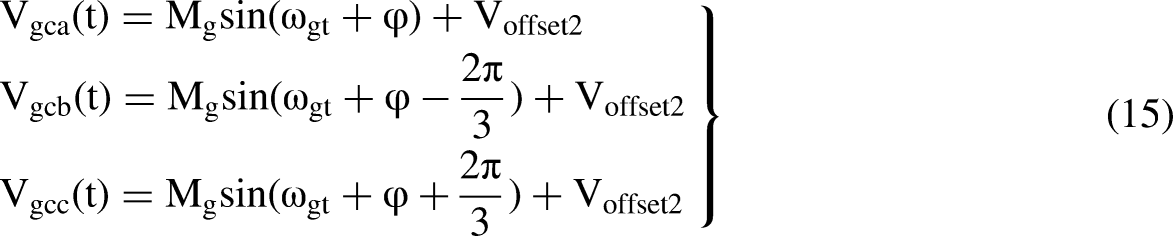
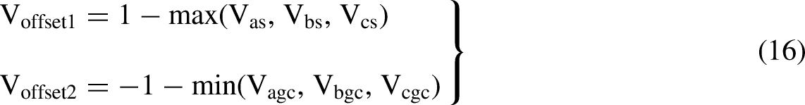
To demonstrate DM in DF mode, acquired through the application of equations offset given in equation (16). Therefore, the addition of reference is still smaller than or equal to 1.15 and it is verified through Simulink response shown in Figure 3.
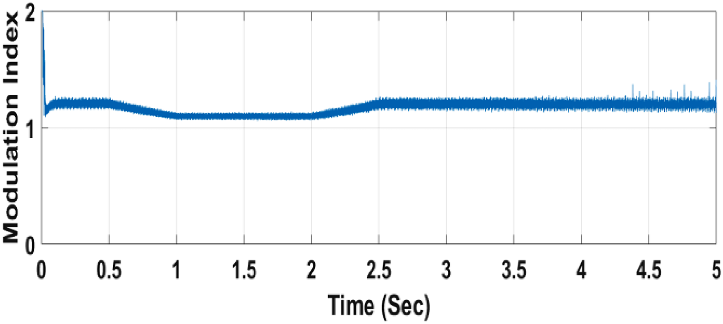
Modulation index of NSC.
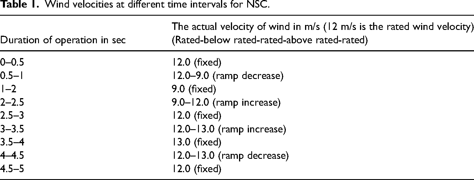
Figure 4 shows the modulation voltage reference signals for the lower and upper switches of NSC. It is noticed that these two modulation voltage reference signals do not overlap with each other; the reference signals for upper switches are always above that of lower switches. Figure 3 shows the modulation index of the NSC, in DF mode, corresponding to the wind speed shown in Table 1. It can be seen that it is less than 1 or 1.15 which is actually similar to theoretical value mentioned in Lei et al. (2012).
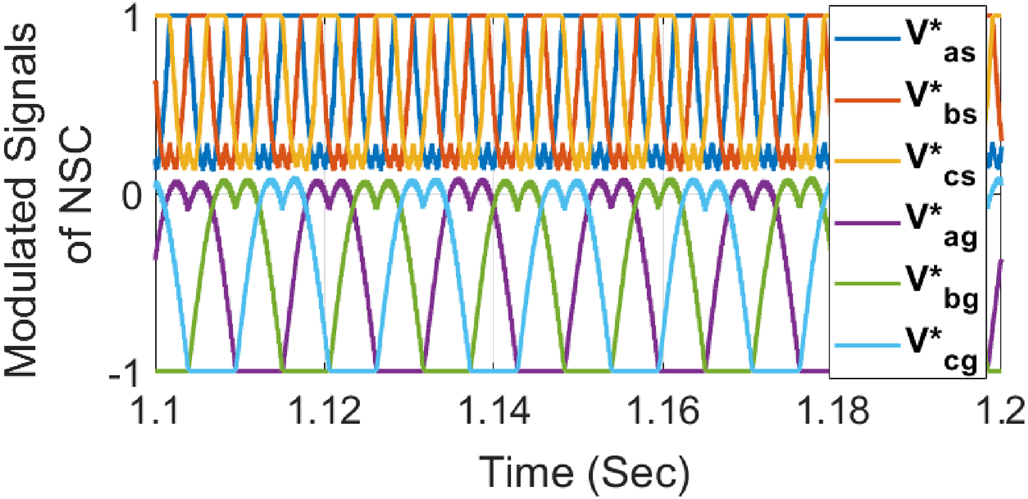
Modulated signals of NSC (Vabcs* & Vabcgc*).
Wind velocities at different time intervals for NSC.
VC scheme of NSC
The NSC can be controlled in two parts: (1) GSC control and (2) MSC control. Figure 5 illustrates the considered control technique to control the NSC-based solar-PV and wind hybrid grid-connected system. The proposed scheme includes both the GSC and MSC operations conducted by a single NSC. Similar to the majority of reduced component converter topologies, there is switching state restriction for NSC (Datta et al., 2022b). The NSC output terminals of the identical phase can link to either + Vdc [for a-phase: T1 & T2-ON & T3-OFF] or 0 V [for a-phase: T1-OFF and T2 & T3-ON], or its upper terminal output to + Vdc and lower terminal output to 0 V [for a-phase: T1 & T3-ON and T2-OFF]. The arrangement of the upper terminal output joined to 0 V and lower terminal output to + Vdc is not permissible [for a-phase: T1& T3-ON and T2-ON] since this creates short-circuit in the common DC-link. To overcome this restriction two modulating references of identical phases must share the space of modulation without crossing each other (Liu et al., 2013b). This can be realized by assigning the upper terminal reference over that of the lower terminal by inserting offsets equally to the references. The tuning of the signal of modulating reference of NSC for 120°-discontinuous modulation is given in detail (Gao et al., 2010; Soe et al., 2011). The regulated reference modulating signals for NSC (upper and lower switches) are given below,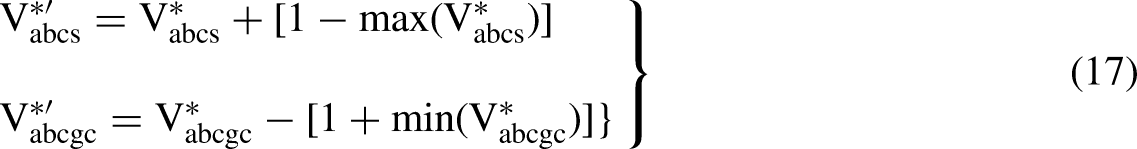
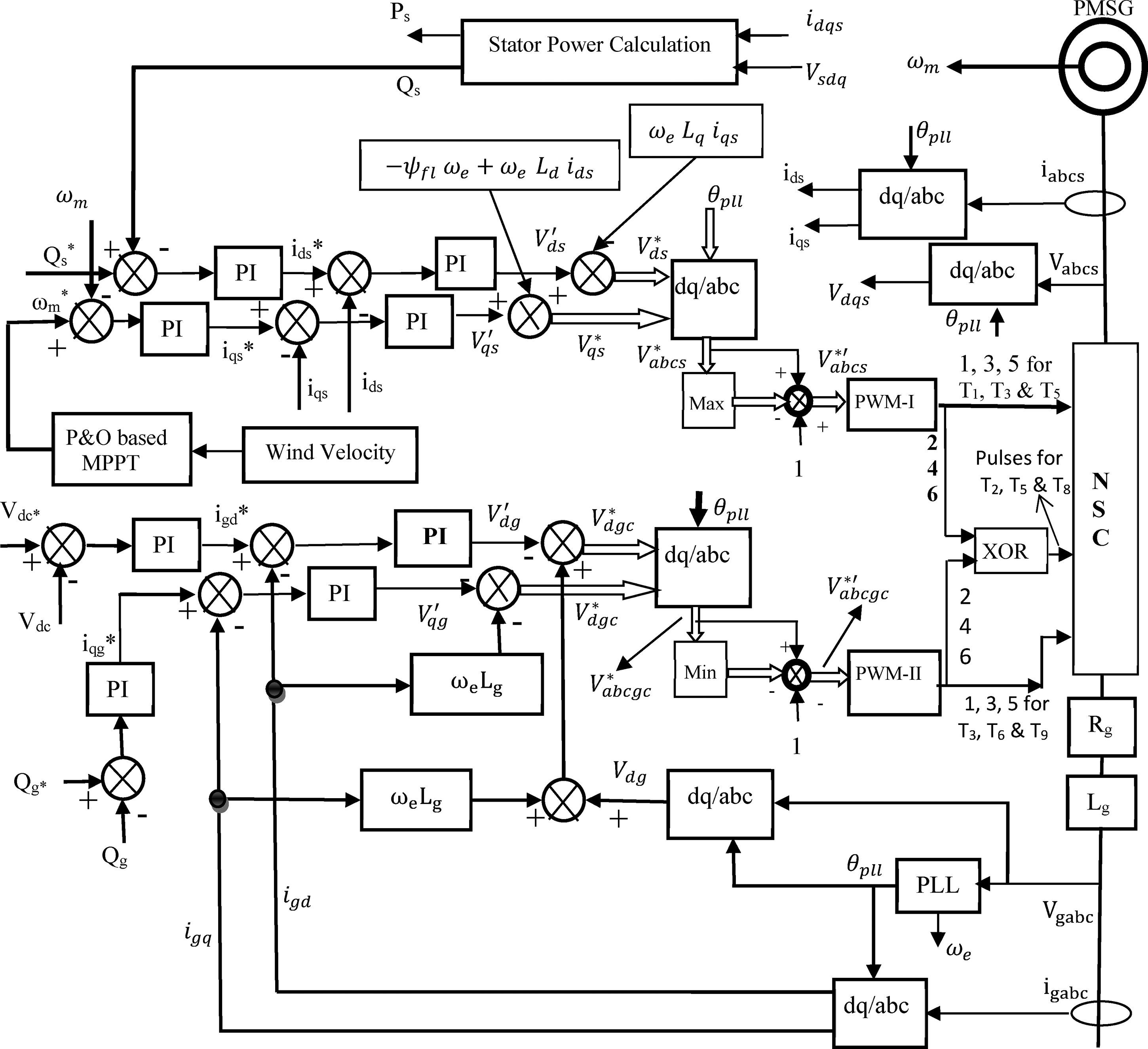
Control scheme for NSC.
To control NSC and realized independent operation of (a) real power exchange between common DC-link capacitor and grid (applying a current of d-axis, for keeping constant DC-link Vdc voltage) and (b) reactive power between grid-side converter and grid (employing current of q-axis). The real power and voltage of DC-link are proportional to idg and are regulated by controlling Vdgc*. Q-axis grid current (iqg) is proportional to imaginary (reactive) power and therefore, it can be regulated by controlling Vqgc*.
In a normal operation, a DC-link voltage controller is utilized to generate the reference-axis current, idg*. And q-axis reference grid current iqg* is considered zero in order to work the system at unity displacement factor. The mathematical model of oriented VC of grid voltage technique is described briefly (Lei et al., 2012). The V*abcs reference voltage is generated by utilizing stator voltage oriented VC method to regulate the current of the stator in its reference value.
In this section, the VC technique based on speed sensor and stator voltage orientation is applied in dq-axis (synchronously rotating) frame of reference. In order to regulate the active power flow between the PMSG (grid and stator) and the grid through NSC in order to follow the MPP of the WT, the d-axis that aligns with the stator-flux vector's magnitude is considered and the stator active and reactive powers are expressed in equations (18) and (19). The mathematical model of the stator voltage-or VC technique is provided in the literature (Datta et al., 2022b; Hava et al., 1998). To control the stator reactive power, current regulated VSC PWM is utilized along with stator current d-axis. Additionally, the stator active power is controlled by using the q-axis stator current.

The modified modulating reference signal (
OPAL-RT digital simulator
The RT-LAB consists of the multiple subsystems used in a complex model to operate at the same period. In order to constitute a distributable and variable parallel real-time simulation system, all these sub-systems are further distributed to multiple CPU nodes. Figure 6 depicts the OPAL-RT laboratory setup, which consists of host system and target simulator. The target simulator furnished with a programmable FPGA. Figure 7 depicts the RT-LAB simulation flowchart of a real-time simulation system. The real-time simulation (Das et al., 2021, Singh et al., 2014) consists of three subsystems: slave subsystem (SS), slave master (SM) subsystem, and slave console (SC) subsystem. There are several slave subsystems inside the model and each SS subsystem contains the computational elements for distributed computation across multiple nodes whereas there is only one master subsystem and it contains computational elements of the model. The SC contains simulink blocks related to acquiring and viewing data. For computing, SM and SS are utilized, and SC is for a graphical user interface. The SM subsystem is also capable of determining in real time and synchronizes the network. The SC subsystem also performs real-time monitoring and communication of key parameter data. It interfaces in real-time with the researcher's PC. These subsystems can run in parallel on multicore or processors without interfering with the primary system's dynamics. To coordinate different system components, the MATLAB simulink model must be provided from the top of RT-LAB under SC and SM (Kumar et al., 2019a). The proposed system shown in Figure 1 with its control schemes is implemented in OPAL-RT laboratory digital simulator, as shown in Figure 8, to verify the responses at practical level. From Figure 8, it has been observed that only one SS and one SM blocks are there, but many computation elements are there inside both the subsystems for implementing the proposed system successfully. In Figure 8, there is a SC subsystem block used for data acquisition and viewing the waveforms of the different signals of the proposed system.
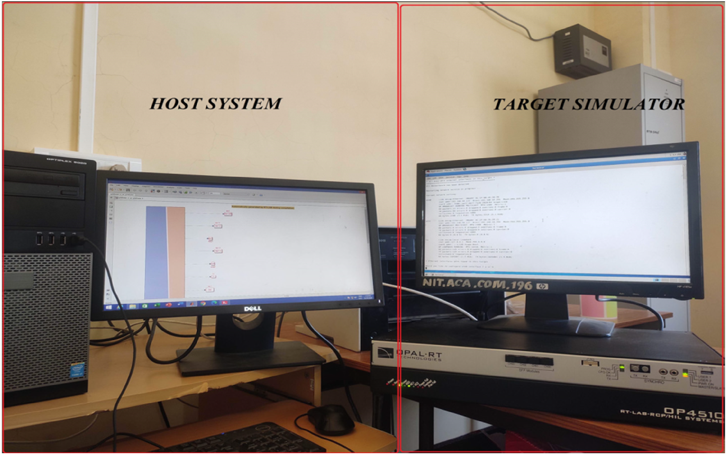
Setup for real-time digital simulation.
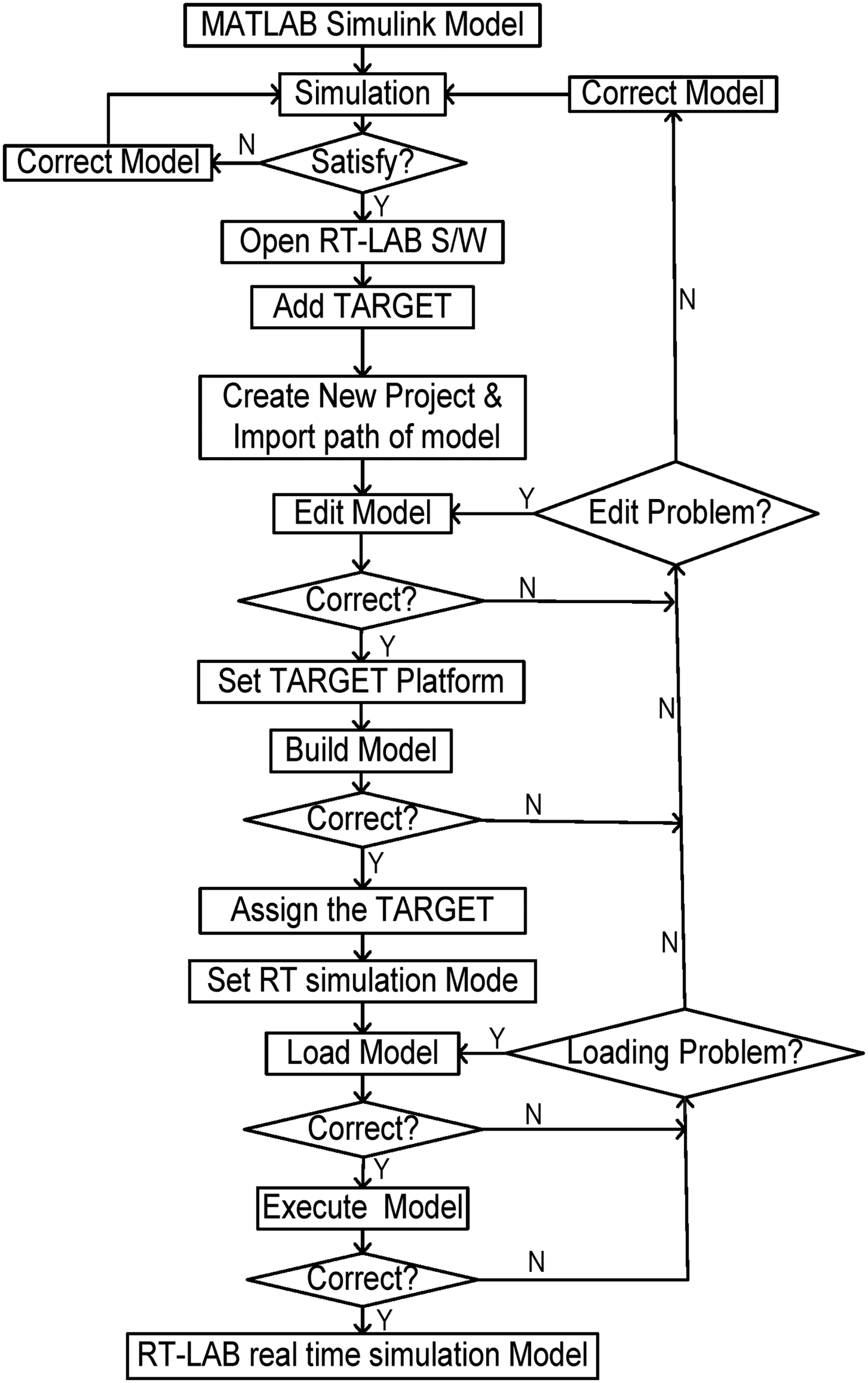
Flowchart for simulation in RT-Lab.
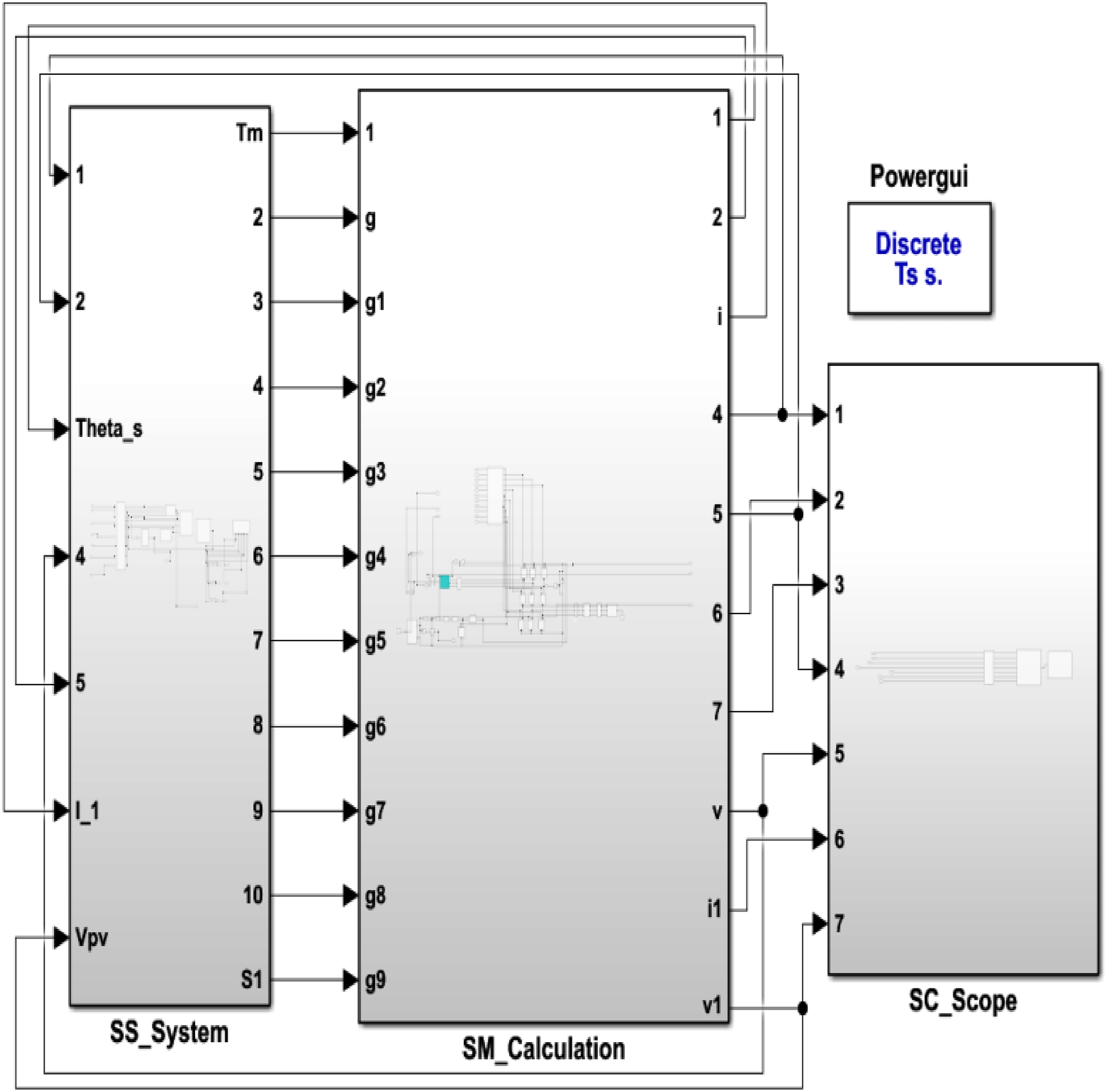
Simulink model implemented by OPAL-RT Lab.
Simulation results and discussions
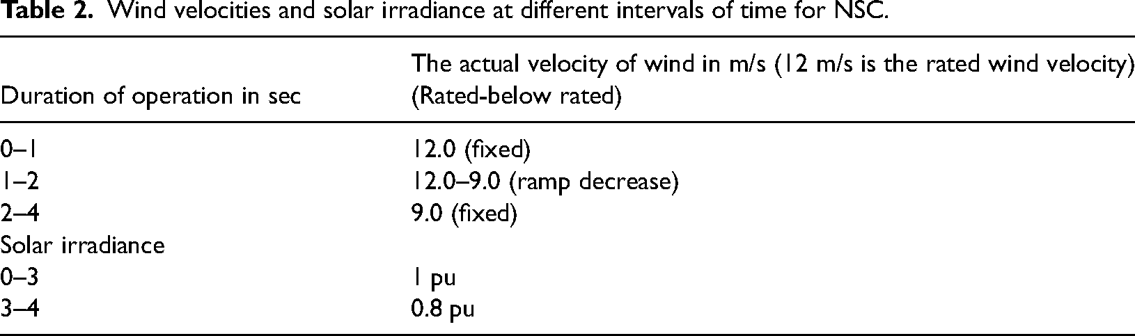
An attempt has been made first time, in this paper, to implement an SWH-based grid-connected system with NSC in OPAL-RT digital simulator to investigate its performance under different scenarios. In this paper, simulation results are obtained using the proposed control scheme for NSC at two sets of conditions: (i) variation [rated-below rated-rated-above rated-rated] in velocity of wind and constant of solar irradiance (1 pu) as stated in Table 1 and (ii) variation [rated-below rated] wind velocity and irradiance of solar [rated-below], as stated in Table 2. Results for case-I and case-2 are presented in detail in the below sub-sections.
Wind velocities and solar irradiance at different intervals of time for NSC.
Dynamic responses of the system at varying wind velocity (rated, below-rated, rated, above-rated, and rated) and constant solar irradiance
In this sub-section, variable wind velocity and constant solar irradiation (rated) are considered, as indicated in Table 1, to study the system behaviors, that is, both steady-state and transient responses and all these responses are obtained from OPAL-RT laboratory as shown in Figures 9 to 12.
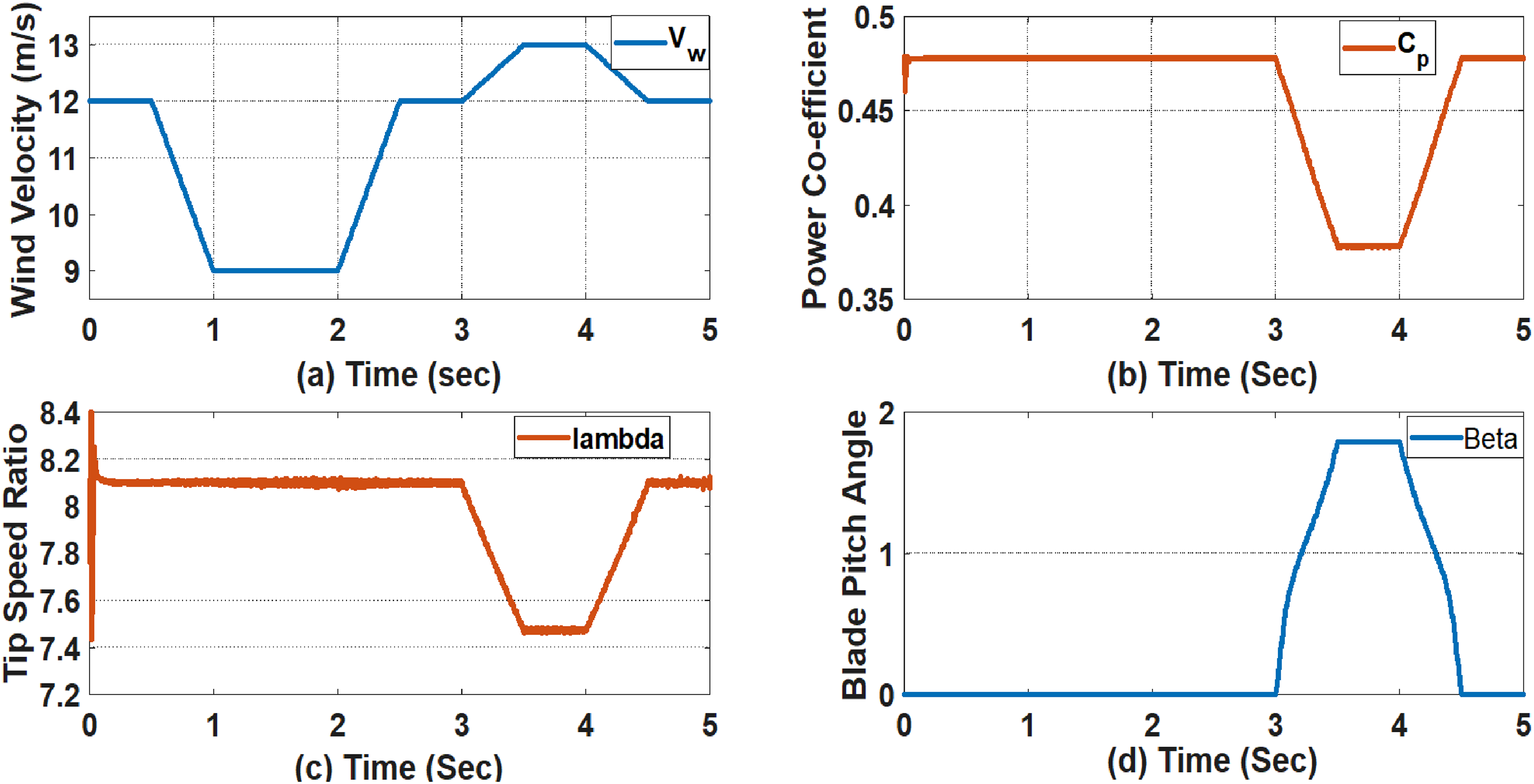
Dynamic results at varying wind velocity and constant solar irradiance: (a) wind velocity (Vw) in m/s, (b) coefficient of wind power (Cp), (c) tip speed ratio (λ), (d) blade pitch angle (β) in degree.
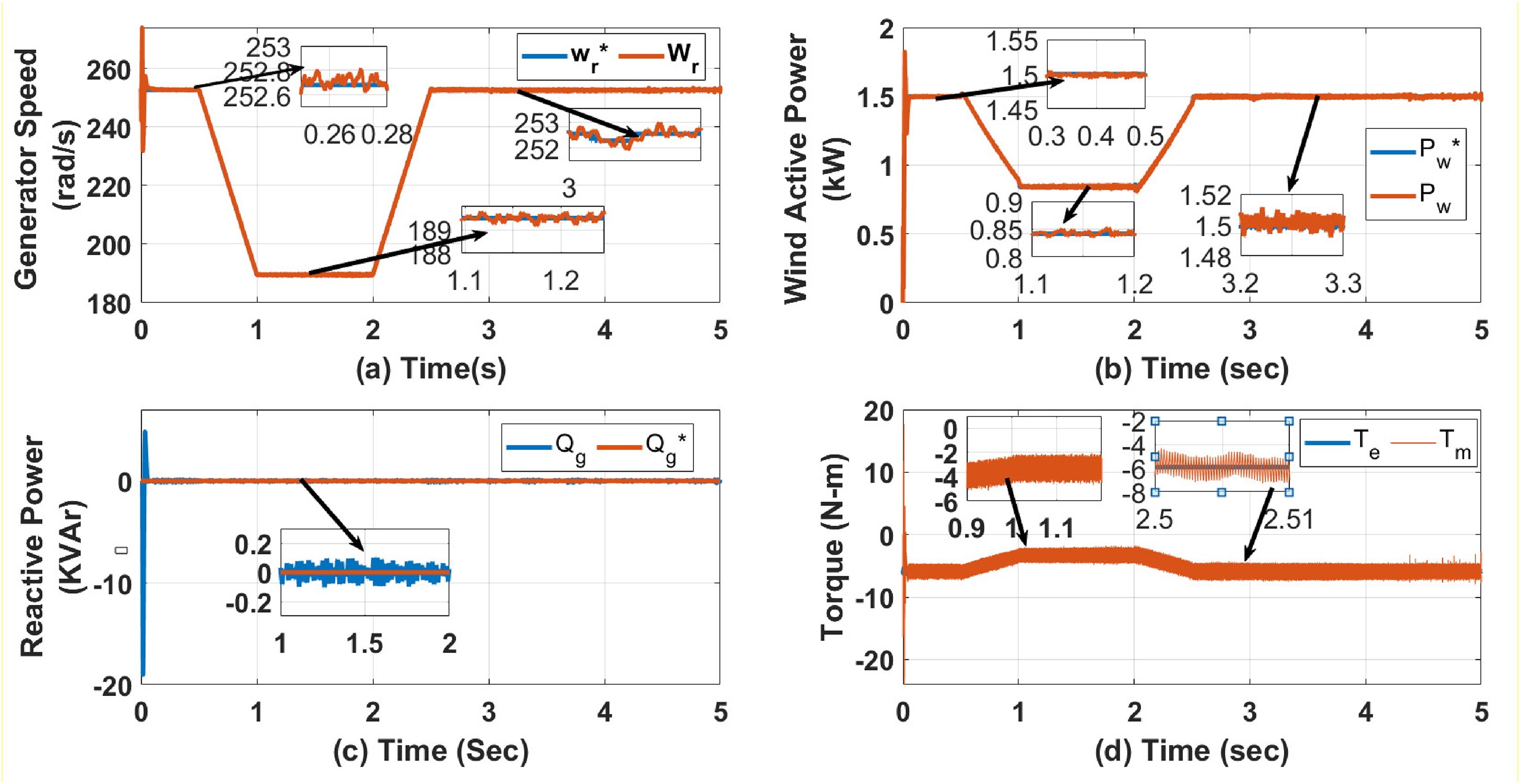
Dynamic results at varying wind velocity and constant solar irradiance: (a) generator rotor speed (Wr) in rad/s, (b) active power of the wind (Pw) in kW, (c) reactive power (Qg) in KVAr, (d) mechanical & electromagnetic torques (Tm and Te) in N-m.
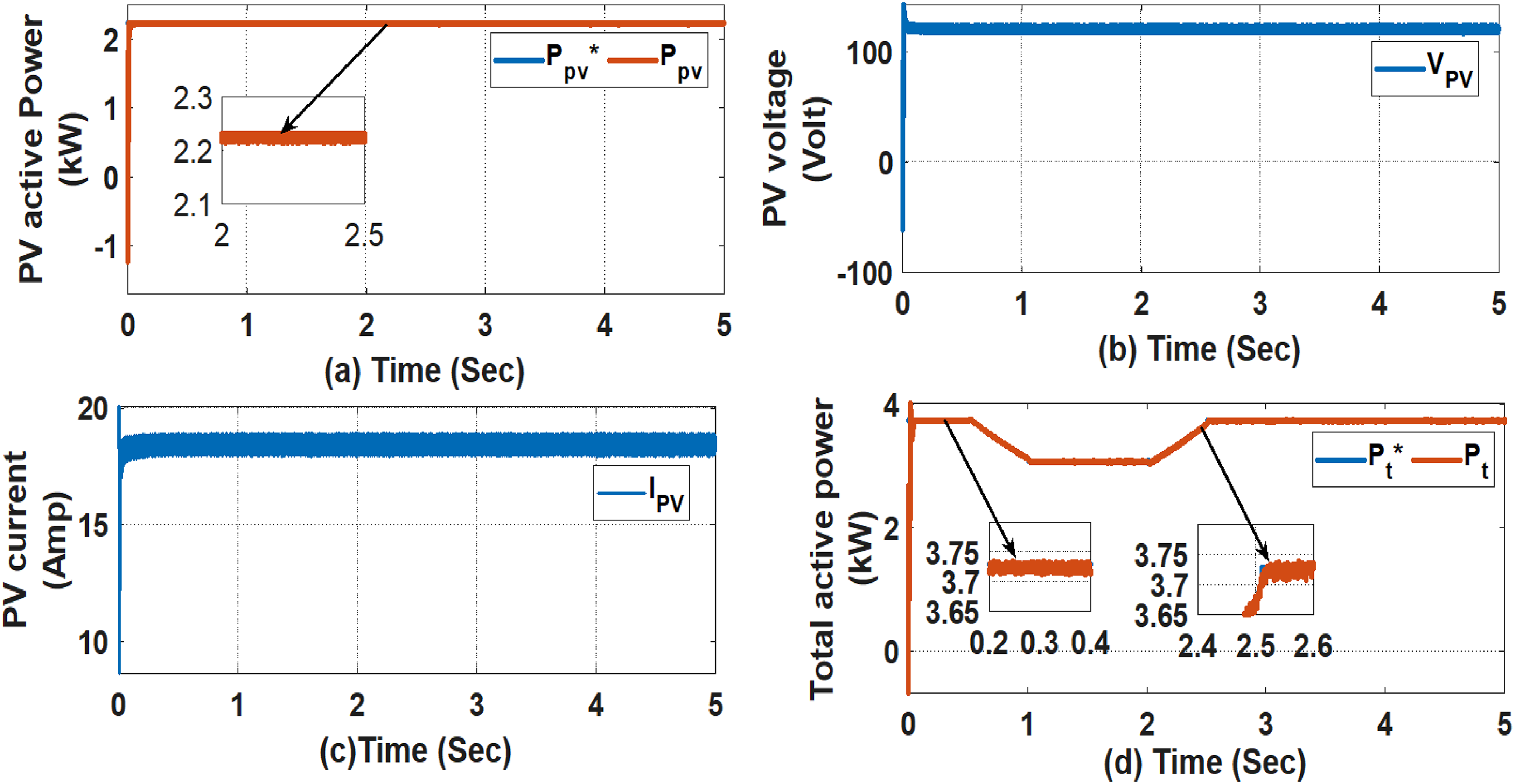
Dynamic results at varying wind velocity and constant solar irradiance: (a) PV active power (Ppv) in kW, (b) PV voltage (Vpv) in volt, (c) PV current (Ipv), and (d) total (Grid) active power (Pt) in kW.
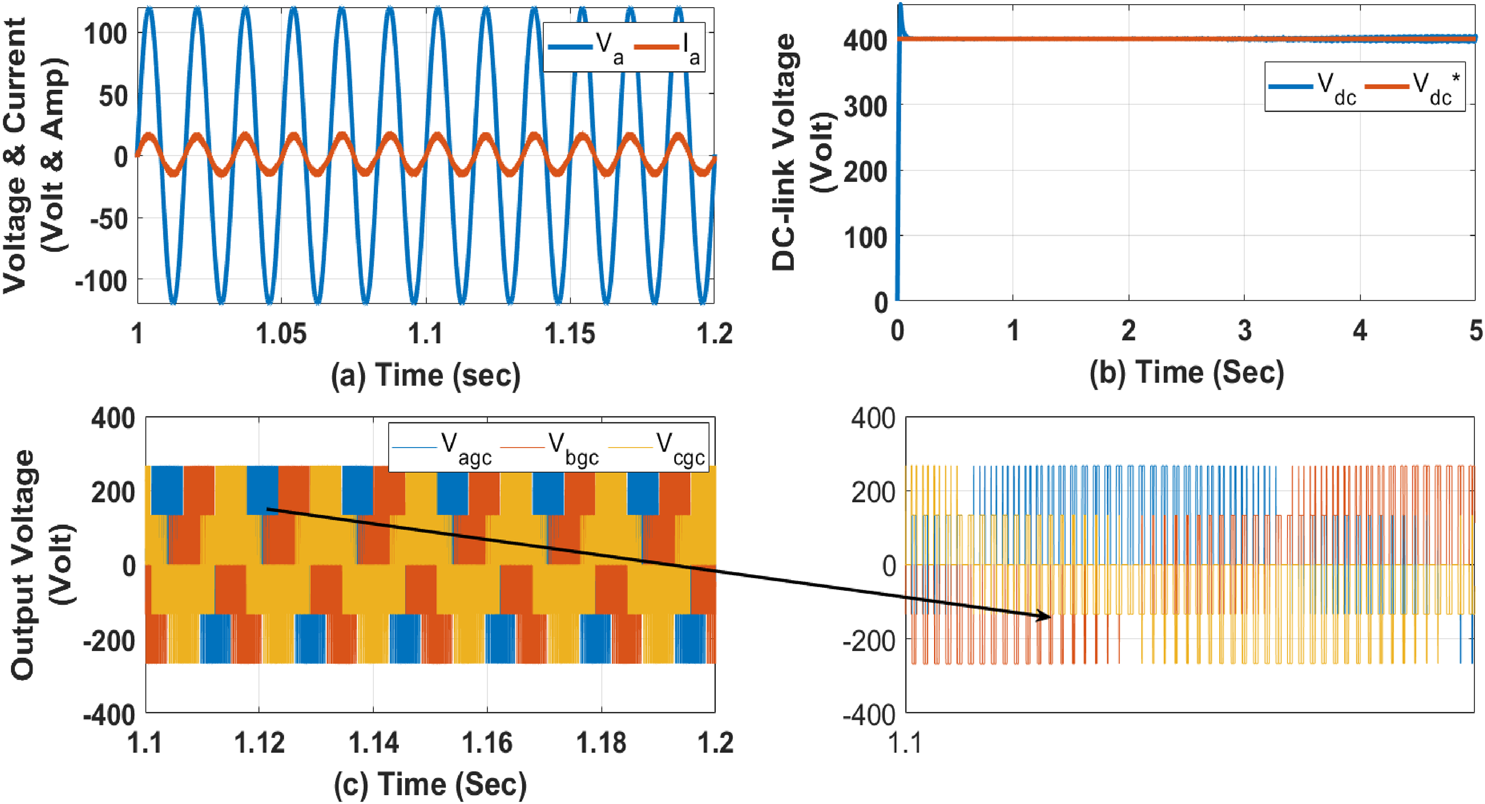
Dynamic results at varying wind velocity and constant solar irradiance: (a) phase-a voltage and current (Va & Ia) in volt and amp, (b) DC-link voltage (Vdc) in volt and (c) o/p voltage of lower terminals of NSC (Vabcgc).
At Vw = 13 m/s, the pitch angle, β increases from 0 value to 1.7° (approx.), Cp drops from 0.48 to 0.38 (approx.) and λ decreases from 8.1 to 7.46 (approx.) as shown in Figure 9. From Figure 10, it is pointed out that the generator's rotor speed, active power, and reactive power are also maintained to their rated and expected values. The active power, voltage, and current from the solar-PV unit are shown in Figure 11(a) to (c) respectively. Rated power 2.3 kW is generated from solar-PV as rated solar irradiance is considered in this sub-section. It has also been observed from Figure 12(b) that the DC-link voltage across the capacitor is remained fixed and tracks its reference value irrespective of the variation in speed from wind. Figure 12(a) shows that the system operates at UPF by managing the flow of reactive power to zero from one end to another end (shown in Figure 10(c)) and hence, total generated active power from solar the and wind is delivered from the source end to grid end as illustrated in Figure 11(d).
Dynamic responses of the system at varying wind velocity and solar irradiance
In this sub-section, simulation results that are obtained at the variable velocity of wind and variable irradiance of solar, as stated in Table 2, have been presented. To study the system behaviors, that is, both steady-state and transient responses, all these responses are obtained from OPAL-RT laboratory as shown in Figures 13 to 15. The steady-state and transient performances of the hybrid system are investigated.
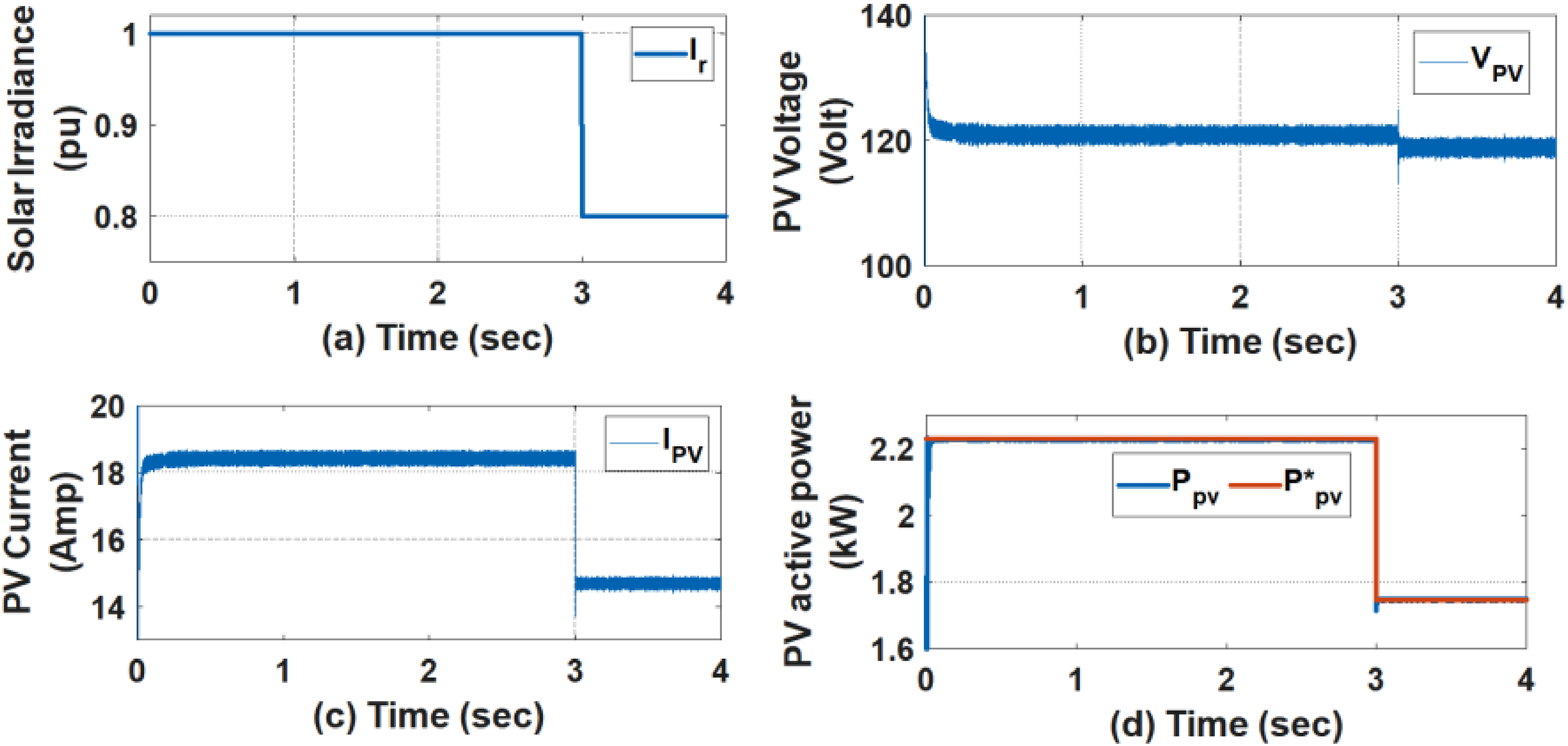
Dynamic results at varying wind velocity and solar irradiance: (a) solar irradiance (Ir) in pu, (b) PV voltage (Vpv) in volt, (c) PV current (Ipv) in amp, and (d) Active power of solar (Ppv) in kW.
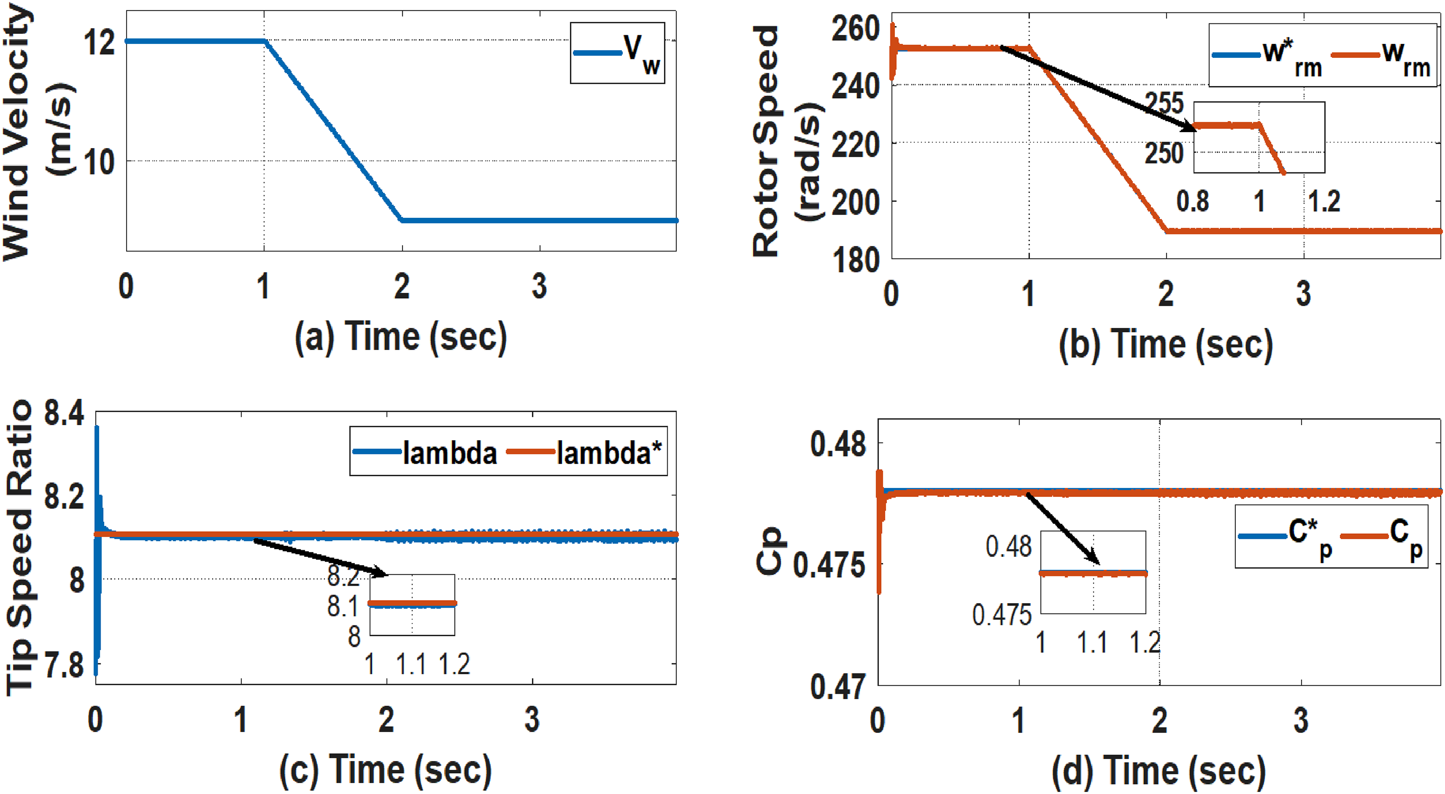
Dynamic results at varying wind velocity and solar irradiation: (a) wind velocity (Vw) in m/s, (b) rotor speed of the PMSG (Wr) in rad/s, (c) tip speed ratio (λ), and (d) power coefficient (Cp).
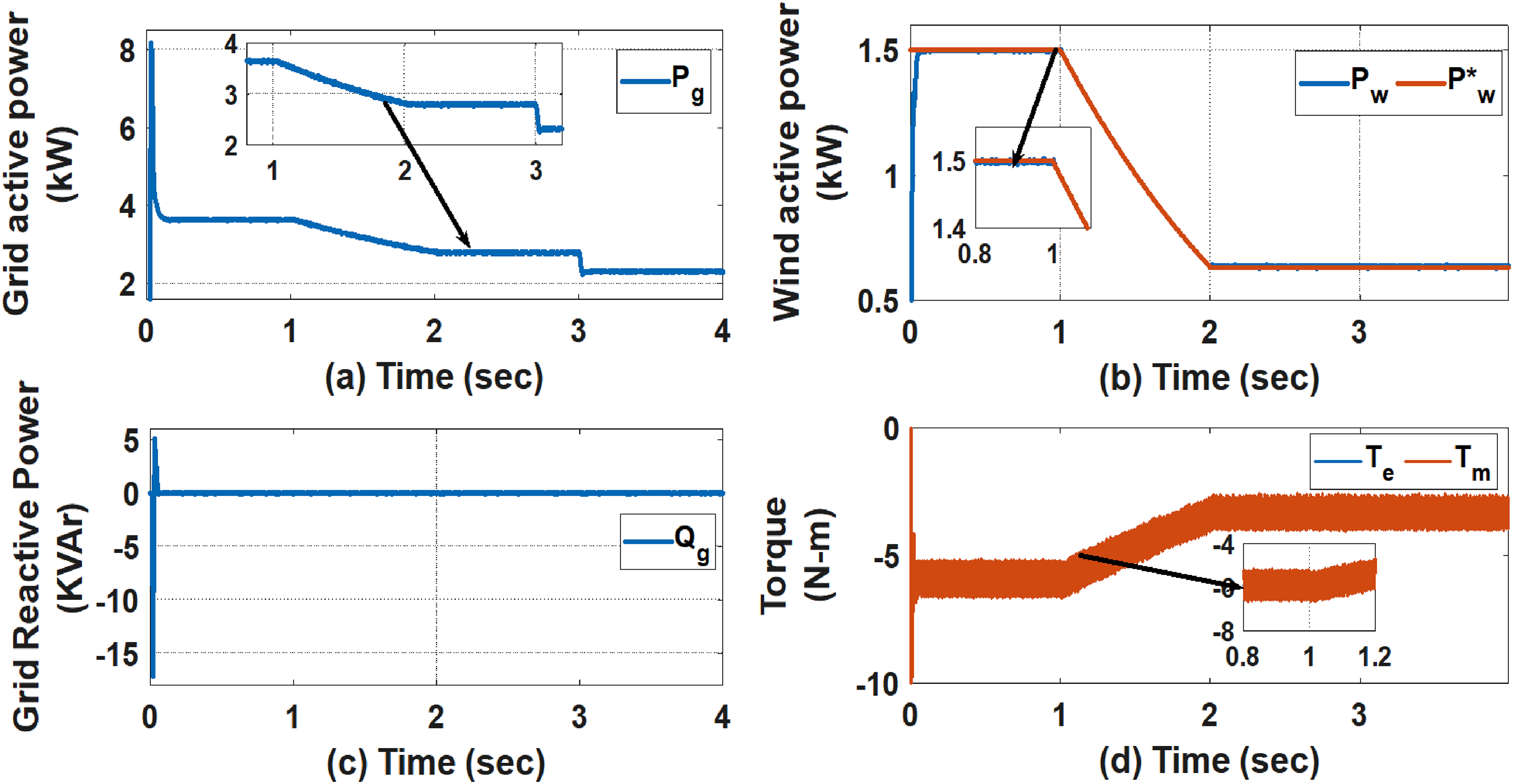
Dynamic results at varying wind velocity and solar irradiance: (a) total (Grid) active power (Pg) in kW, (b) active power of the wind (Pw) in kW, (c) grid reactive power (Qg) in KVAr, and (d) mechanical and electric torques (Tm & Te) in N-m.
It has been observed from the responses, shown in Figures 13 to 15, that all the responses of the study system have accurately tracked their corresponding reference values at a steady state under the effect of the proposed control scheme at varying wind speed and solar irradiance.
Conclusion
In this study, a hybrid grid-connected system, consisting of PMSG-based WT, solar-PV, boost converter and NSC, is proposed for reducing cost of components, component count, and switching losses, and hence, increases system efficiency. A new control scheme based on VC concept is proposed for regulating NSC for achieving VSCF operation at UPF under varying sources. Also, 120° discontinuous modulating technique is integrated with the control scheme of NSC for reducing switching losses. A P & O algorithm-based MPPT control scheme is considered for unidirectional boost converter of the solar-PV unit to regulate it and also to capture maximum power from solar-PV. P & O algorithm-based MPPT and blade angle algorithm are incorporated in the proposed control scheme of NSC to capture maximum power from wind and also to confine power generation of wind to its rated value respectively.
The proposed system is implemented in an OPAL-RT laboratory to investigate its dynamic performances under various real-life scenarios; like (i) variation in the velocity of wind (rated- below rated-above rated-rated) and constant solar irradiance, and (ii) variable wind velocity and solar irradiance. All-time-domain responses of the proposed hybrid system are obtained using OPAL-RT digital simulator with MATLAB/Simulink software and all responses are studied thoroughly. The time responses show that the proposed control scheme is adequately skillful to regulate the system and make it enable to track the MPP of varying solar irradiance and wind velocity by maintaining zero reactive power exchange, that is, operated at UPF. Additionally, the blade pitch-angle control algorithm under consideration is also very effective at controlling the suggested system and achieving the maximum active power at its rated power level at a variable that is higher than the wind's rated velocity. It is also noticed from the results that the effectiveness of the proposed new control scheme on the hybrid study system and it provides good dynamic responses in terms of very less oscillations during transient, almost negligible (i.e. 0.0001 approx.) steady-state error etc. under variation of input sources.
Footnotes
Author contributions
All authors contributed equally to this work.
Declaration of conflicting interests
The authors declared no potential conflicts of interest with respect to the research, authorship, and/or publication of this article.
Funding
The authors received no financial support for the research, authorship, and/or publication of this article.