
Abstract
This article investigates the fragmentation of rock during the indentation process with a conical pick. The study explores the impact of indentation dip angle, indentation spacing, and confining pressure on rock fragmentation through simulation using the discrete element method. Rock models of coal and red sandstone are created and calibrated for the simulation. The findings indicate that the indentation force increases exponentially with the increase of indentation dip angle for both coal and red sandstone. The specific energy increases first and then decreases with the increase of indentation dip angle. The maximum specific energy is found in the condition of indentation dip angle of 25° for red sandstone, while it is 20° for coal. The indentation force increases logarithmically with the increase of indentation spacing tending to be an unrelieved indentation condition. The optimal indentation spacing with the lowest specific energy is determined to be 50 mm for breaking coal and 34 mm for breaking red sandstone. Additionally, the indentation force increases exponentially for coal while it increases linearly for red sandstone with the increase of the confining pressure. For both coal and red sandstone, specific energy increases with the increase of the confining pressure.
Introduction
According to the World Coal Association, coal plays a major role in delivering power across the globe. It is still the world's largest source of electricity and will still contribute 22% in 2040. This figure is even higher in emerging markets, that is, coal will fuel 39% of electricity in South East Asia in 2040. At present, mechanical rock breaking is still the main method of coal mining. Compared with blasting and other methods, mechanical rock breaking has the advantages of being continuous, efficient, and relatively safe. Therefore, many kinds of mining and excavation equipment such as shearer, road-header, and planer are widely used in mining and underground space excavation projects. The common point of the above mining equipment is that they all have a cutting head equipped with cutting picks, such as the spiral drum of the shearer. Firstly, the picks wedge into the rock first and then cut the rock with the rotation of the cutting head. Consequently, the indentation process of picking is the foundation stage for rock cutting. According to the field and literature research, it is found that there are still many problems in applying mining equipment based on cutting picks, such as low efficiency of hard rock cutting, high energy consumption, heavy dust, low lump coal rate, and so on. Furthermore, the increase in mining depth will increase the strength of coal and rock, the reduction of the adaptability and efficiency of mining equipment, the increase cutting pick consumption. Therefore, the rock-breaking mechanism has been an important research topic for a long time.
In the past few decades, much work has been done on rock-cutting mechanisms, and many theoretical models of rock-cutting have been proposed (Evans, 1984; Goktan et al., 2005; Li et al., 2018). However, the study of the rock indentation mechanism is still an important task of rock fragmentation which has not been solved yet. The theoretical research on the process of rock indentation (such as the mechanical analysis of force, deformation, fracture, and crushing of rock during the indentation process) has not been mature enough at present. Tranter (1948) obtained the theoretical solution of stress distribution in a semi-infinite wedge under plane loading conditions through Merlin transformation. Sneddon (1948) obtained the calculation method of stress distribution in elastic material during a rigid cone wedging into the surface of the semi-infinite elastic media. Hill et al. (1947) and Outmans (1960) proposed a failure mechanism when the pick wedges into plastic materials, but it is also not applicable to brittle materials such as rock. Cheatham (1958) proposed a theoretical indentation force model based on the assumption that rock is an isotropic rigid and plastic material. However, rock cracks in the brittle mode under most conditions, and plastic flow only occurs under the condition of high confining pressure. Karal et al. (1964) analyzed the stress distribution near the pick tip when wedging into elastic media. Paul et al. (1965) established a theoretical model to explain the process of pick wedging into brittle materials. Pariseau et al. (1967) obtained the relationship between indentation load and indentation depth by analyzing the rock indentation process with a wedge pick. Subsequently, Benjumea et al. (1969) improved the model to apply it to the analysis of the indentation process of anisotropic materials. Miller (1971) studied the indentation process with picks by theory and indentation tests. They found that the envelope of the peak forces with conical picks was nonlinear while it was linear for wedge picks. Then, they proposed the theoretical model of the indentation force under confining pressure by using the approximate plane strain method. Dutta (1972) found that during the indentation process, it was not the pick tip but a dense nucleus to crack rock. Meanwhile, the friction between the dense nucleus and the rock had a great influence on the indentation force. Khalaf et al. (1980) found that the energy consumed was positively correlated with the rock powder particle size of the dense nucleus during rock indentation. Sanio (1985) thought that the stress in the dense nucleus beneath the pick tip was approximately a state of hydrostatic pressure. The author proposed that the macro cracks generated and propagated from the boundary of the dense nucleus radially to the interior of the rock. The generation and propagation of cracks were determined by the initial defects of the rock. Damjanac et al. (1995) established a numerical model of rock indentation with wedge pick based on the assumption that coal and rock are elastoplastic materials. They studied the initial stage of the indentation process by simulation and found that the rock cracking process was influenced by the wedge angle of the pick, strength, and elastic modulus of the rock. Chiaia (2001) studied the fracture mechanism of brittle material by an indenter based on the dense nucleus theory. Chen and Labuz (2006), Chen et al. (2009) studied the formation and propagation of cracks in the process of rock indentation by acoustic emission technology. They thought that the length of macro cracks was affected by the grain size of the coal, and the wedge angle had less effect on the direction of macro crack propagation. Mo et al. (2012) conducted the simulation of rock indentation with a disc cutter, and concluded that the cracks were generated and propagated in tensile failure mode. Shang et al. (2012) studied the free-surface-assisted rock fragmentation with a tunnel boring machine (TBM) cutter using the peridynamics method. However, the mechanism of fragmentation during the rock indentation process is still not deeply understood, especially in the conditions of heterogeneous rock and complex geological environments. Jiang et al. (2020) studied the rock indentation process assisted by a high-pressure water jet using the coupled smoothed particle hydrodynamics/finite element method (SPH/FEM) and found that the high-pressure water jet can decrease the impact force effectively. Wang et al. (2021) found the uniaxial confining stress is more significant than the brittleness of rock for influencing the rock cuttability based on rock indentation tests. Xue et al. (2021) studied the rock fragmentation process with a TBM cutter using the discrete element method (DEM) considering different joint parameters (e.g. joint inclination, orientation, and spacing). Dai et al. (2021) studied the influence of back rake angle and mechanical properties of rocks on the failure characteristic of rock indentation with polycrystalline diamond compact (PDC) cutters. Yang et al. (2023) investigated the estimation of rock mechanical properties by indentation tests with a conical pick. They found that there are linear relationships between the uniaxial compression strength (UCS), E, Brazilian tensile strength (BTS), and indentation indices (i.e. energy per unit, indentation modulus of the first peak) with high determination coefficients. Wang et al. (2023a) investigated the key factors (i.e. impact velocity and rock strength) of rock breaking by indentation experiments based on a percussive penetration experimental system. Wang et al. (2023b) studied the free face-assisted rock breaking mechanism with TBM cutters based on the frequency domain electromagnetic (FDEM) method first and found that a spacing of 75 mm and a height of 125 mm can bring the largest fragment area and the highest rock breaking efficiency.
The current study aims to investigate the impact of indentation parameters and confining pressure on rock fragmentation during indentation using simulation with the DEM. Initially, models for rock indentation are constructed to account for indentation dip angle, indentation spacing, and confining pressure. Subsequently, the effect of indentation parameters and confining pressure on the indentation process is analyzed, focusing on the rock cracking process, forces, and efficiency.
Discrete element model of rock indentation
Calibration of micro parameters
The DEM particle flow code (PFC) software is used for numerical simulation. The calibration of micro parameters of rock samples should be conducted first. As there is no certain relationship between micro parameters and macro properties of the DEM model, the calibration of micro parameters is a process of trial and error. In this article, the parallel bond contact model (PBCM) is used in building rock models. The uniaxial compression test and Brazilian tensile test are conducted to calibrate the micro parameters according to Li (2020). Figure 1 shows the rock models for the uniaxial compression test and Brazilian tensile test.
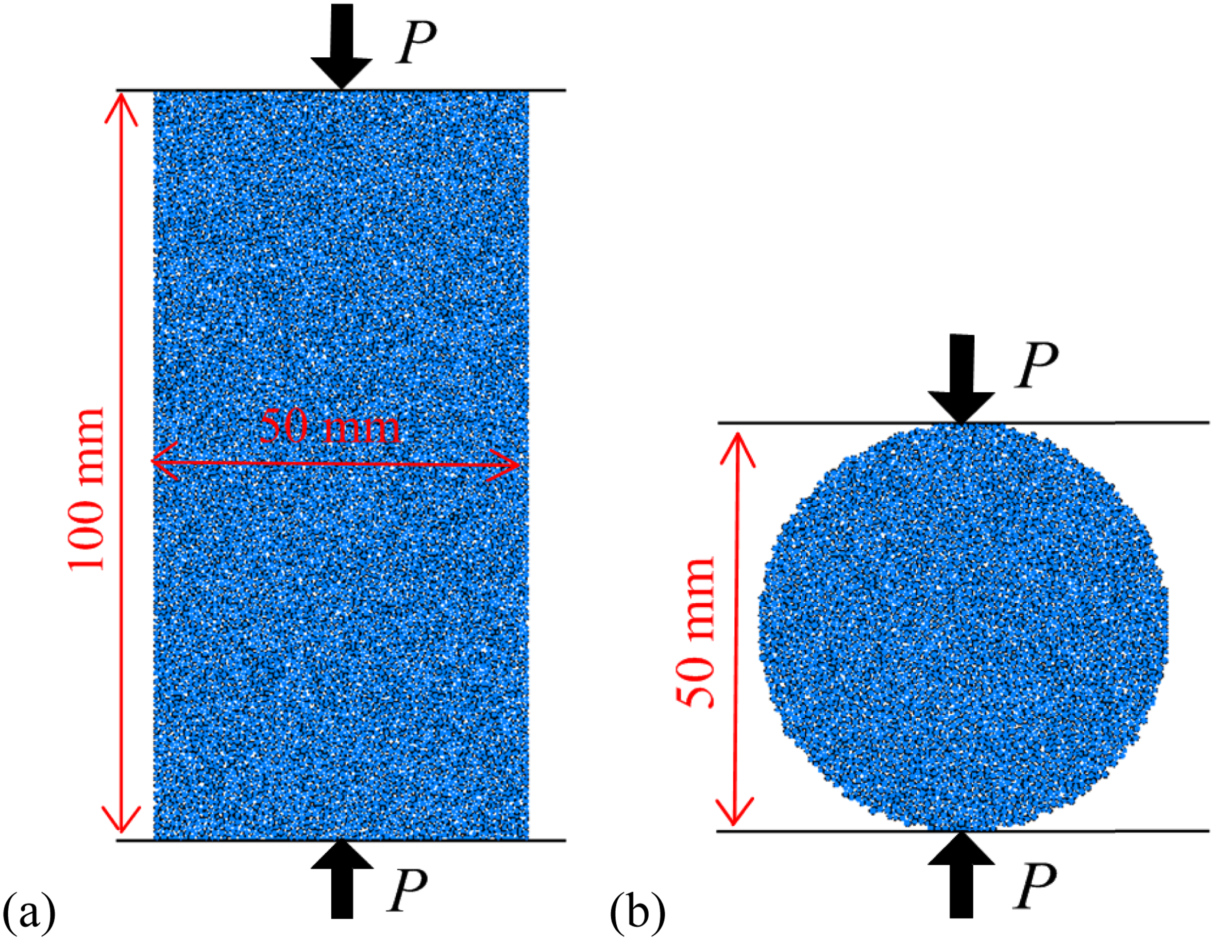
Rock models for (a) uniaxial compression test and (b) Brazilian tensile test.
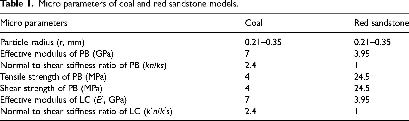
To investigate the rock fracture mechanism during indentation, two different rock samples, that is, coal and red sandstone, are used in the numerical simulation. The micro parameters of coal and red sandstone models are calibrated and listed in Table 1. Accordingly, the macro properties of rock samples, like UCS, BTS, Young's modulus (E), and Poisson's ratio (μ), obtained by experiment and simulation are summarized in Table 2. The BTSs of coal and red sandstone models are larger than those obtained by experiments. The insufficient restriction of the PBCM on the relative rotation between particles results in the ratio of UCS to BTS being smaller than that of real rock samples which is the inherent defect of PBCM (Cho et al., 2007). Figures 2 and 3 show the crack distribution of coal and red sandstone that failed in the uniaxial compression test and Brazilian tensile test. In comparison, the main crack of red sandstone throughout the sample by primarily brittle failure, while cracks propagate with tiny chips in the tests of coal. The calibrated rock models perform well in simulating the cracking process of rocks. Consequently, it's reasonable to use the calibrated rock models to investigate the rock fracture mechanism during indentation.
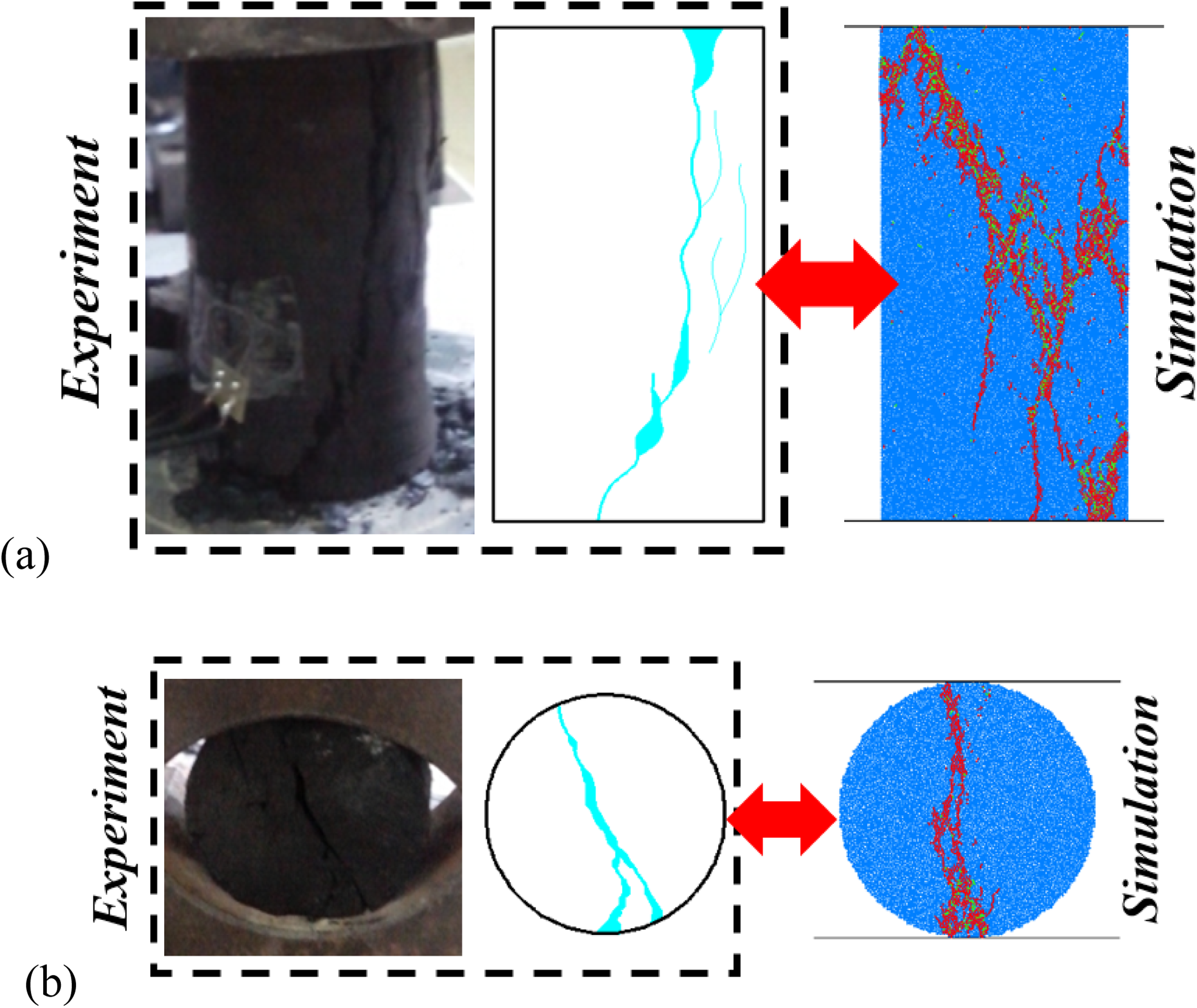
Failure diagram of coal in experiments and simulations: (a) uniaxial compression test and (b) Brazilian tensile test.
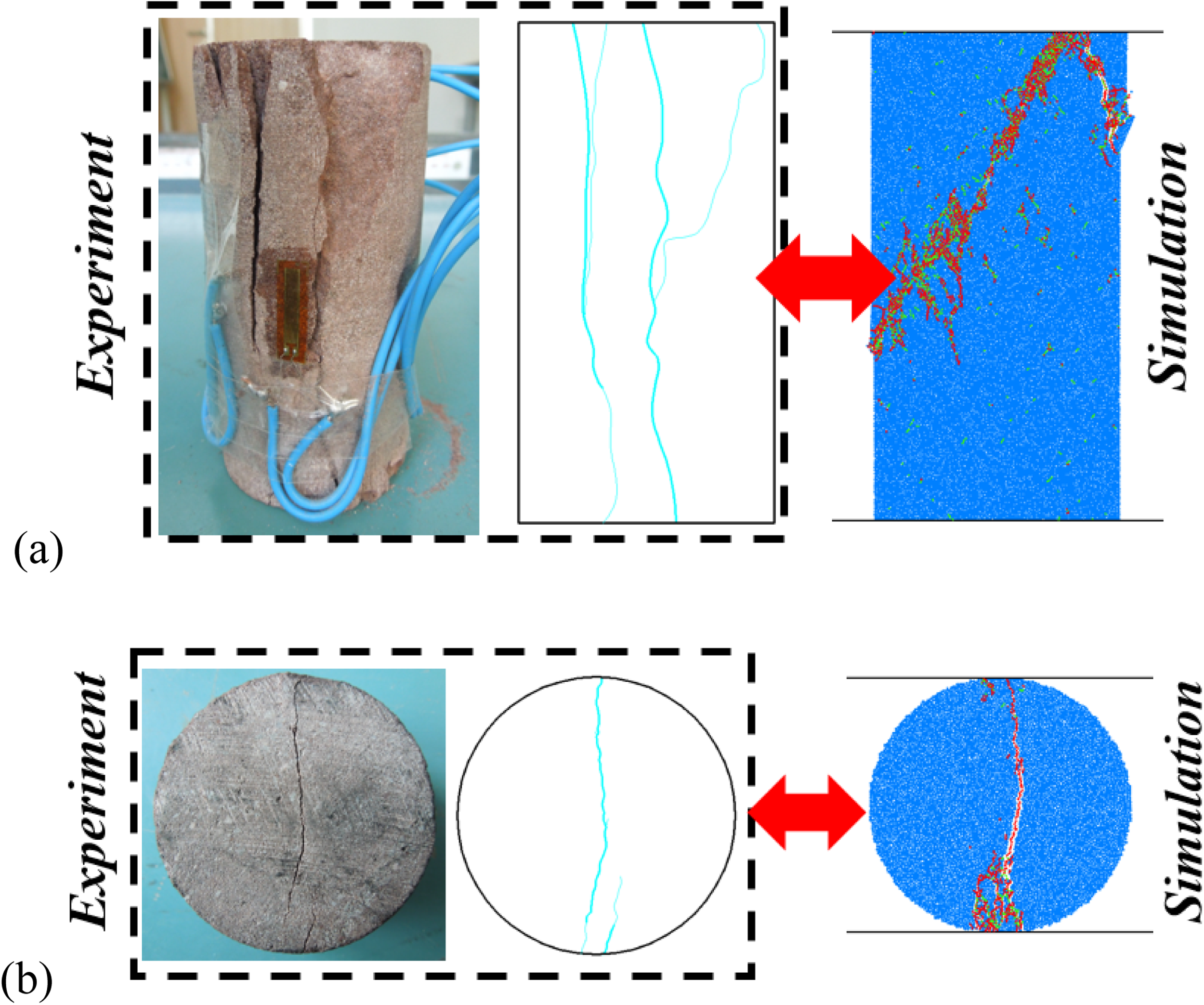
Failure diagram of red sandstone in experiments and simulations: (a) uniaxial compression test and (b) Brazilian tensile test.
Micro parameters of coal and red sandstone models.
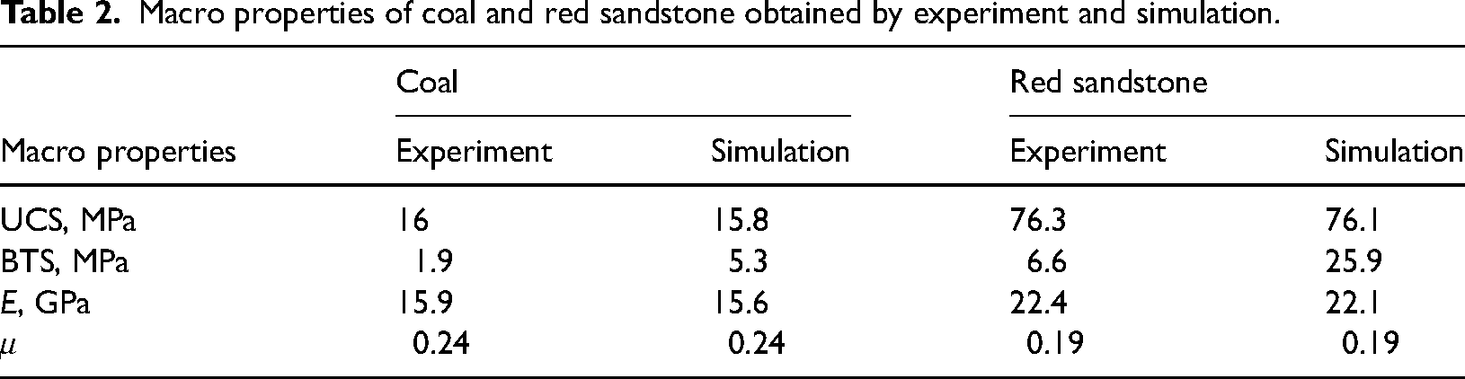
Macro properties of coal and red sandstone obtained by experiment and simulation.
Establishment of rock indentation model
Based on the calibrated rock models, the rock indentation models are built as Figure 4 to investigate the effect of indentation dip angle, indentation spacing, and confining pressure. The indentation dip angle is the angle between the pick axis and the indentation direction. It equals the skew angle of the pick mounted on the shearer drum. The indentation spacing is the distance between adjacent picks, which has an important effect on chip formation and cutting efficiency. In the indentation model, the confining pressure is applied by a servo algorithm controlling the speed of side walls (Li et al., 2017). The variables used in the numerical simulations are listed in Table 3. The indentation depth is 5 mm.
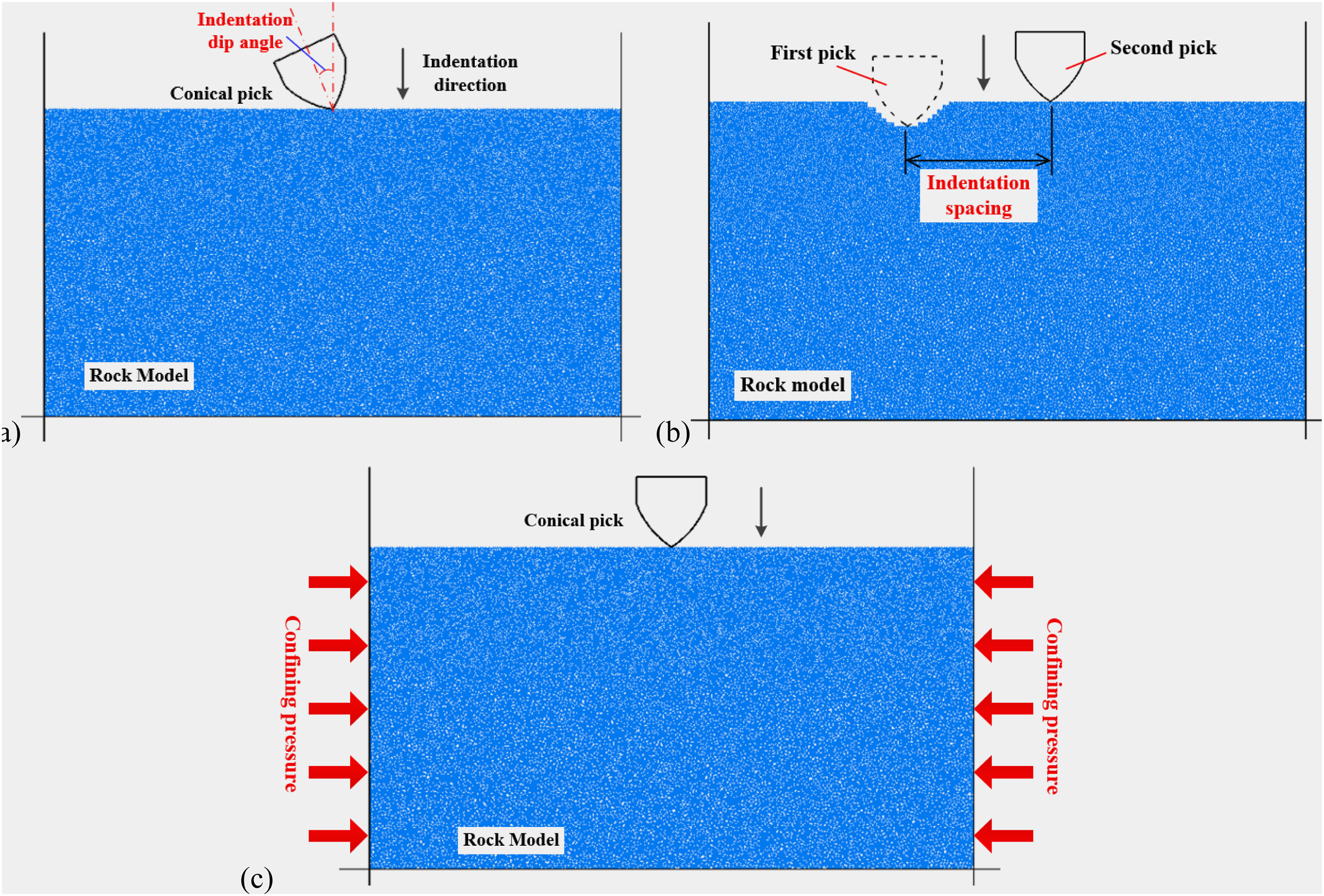
Rock indentation models: (a) indentation dip angle, (b) indentation spacing, and (c) confining pressure.
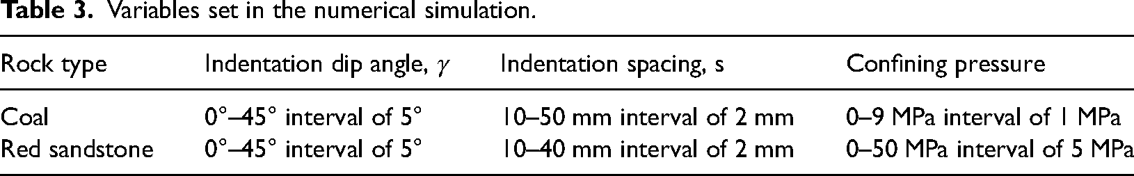
Variables set in the numerical simulation.
The dimensions of the rock model are 150 × 80 mm containing about 28,575 particles. The radius of these particles ranges from 0.21 to 0.35 mm. The conical pick is simplified as the alloy head and imported into PFC as rigid elements (i.e. wall). The tip angle of the alloy head is 76° with a diameter of 25 mm. The time step is about 1.5 × 10⁻⁸ s/step auto-calculated based on the number of particles and the hardware of the computer. To reduce the simulation time, the indentation speed is set as 1 m/s. The displacement of the pick is about 1.5 × 10⁻⁵ mm in one calculated step which is much less than the radius of the smallest particle of 0.21 mm. It ensures the simulation is stable and valid. The indentation force and lateral force acting on the pick and the information of micro fractures are recorded during simulation.
Validation of the rock indentation model
To validate the rock indentation model, the indentation tests with different cutting thicknesses are conducted using a compression testing machine shown in Figure 5. According to the rock failure diagrams with different cutting thicknesses shown in Figure 6, the cracks propagate to the free surface as a “V” shape with a dense nucleus beneath the pick tip. And triangular pyramid-shaped chips are formed. The indentation forces increase linearly to the peak and rapidly reduce to the residual shown in Figure 7.
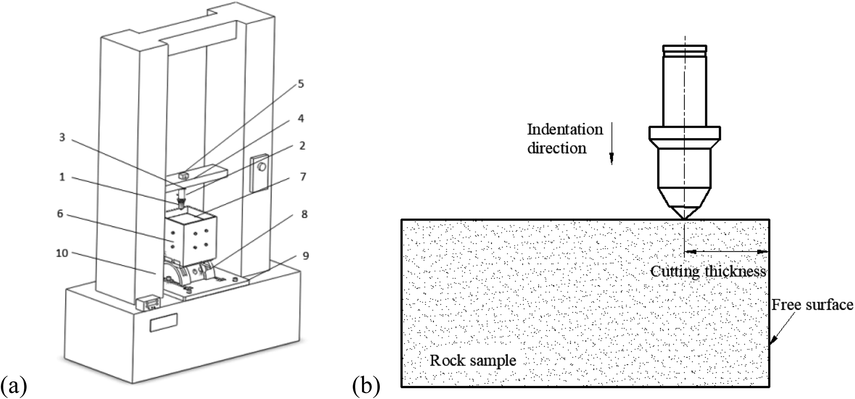
Rock indentation test: (a) compression testing machine and (b) rock indentation test diagram.
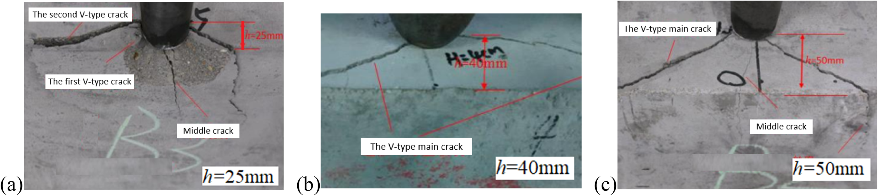
Rock failure diagrams with different cutting thicknesses in indentation tests: (a) 25 mm, (b) 40 mm, and (c) 50mm.
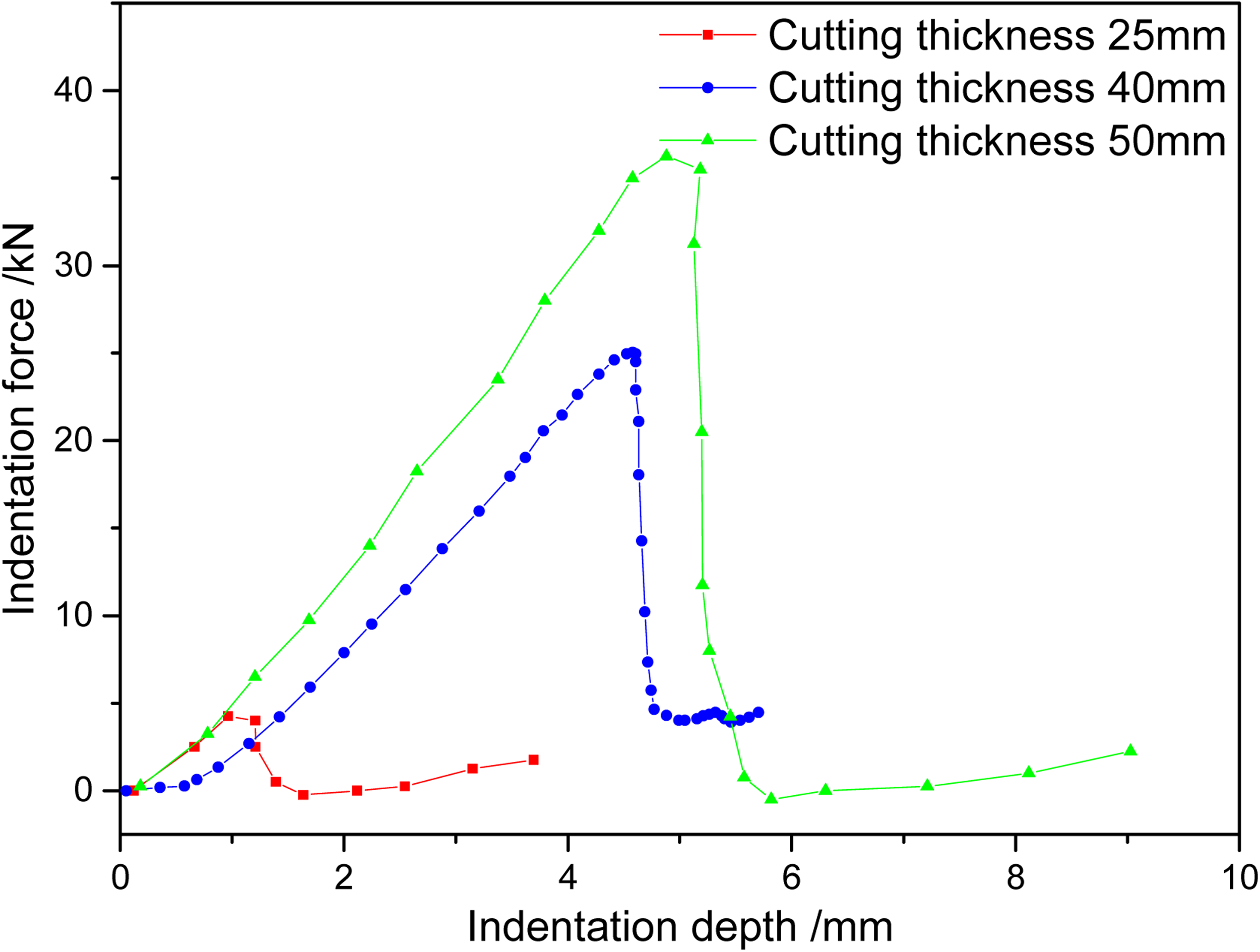
The curves of indentation force with different cutting thickness in indentation tests.
According to the indentation tests, the indentation simulation with different cutting thicknesses was conducted. The rock failure diagrams are shown in Figure 8. It shows that a crush zone is formed beneath the pick tip similar to the dense nucleus in the experiment. The macroscopic cracks are formed from the crushing zone and propagate to the free surface. And triangular chips are formed. The curves of the indentation force obtained by the simulation are shown in Figure 9. The indentation force increases continuously to the peak and then decreases rapidly during the simulation process, and the fluctuation trend is in good agreement with the indentation tests. As the fine defects in the actual rock sample are not considered in the rock model built by DEM, the peak indentation force obtained by simulation is larger than that obtained by experiments shown in Figure 10. However, there is a linear relationship with a correlation coefficient of R2 = 0.9964 between the peak indentation forces obtained by the simulation and experiments. Consequently, it is reasonable to use this rock model to study the regularity of indentation parameters on rock indentation-breaking characteristics.
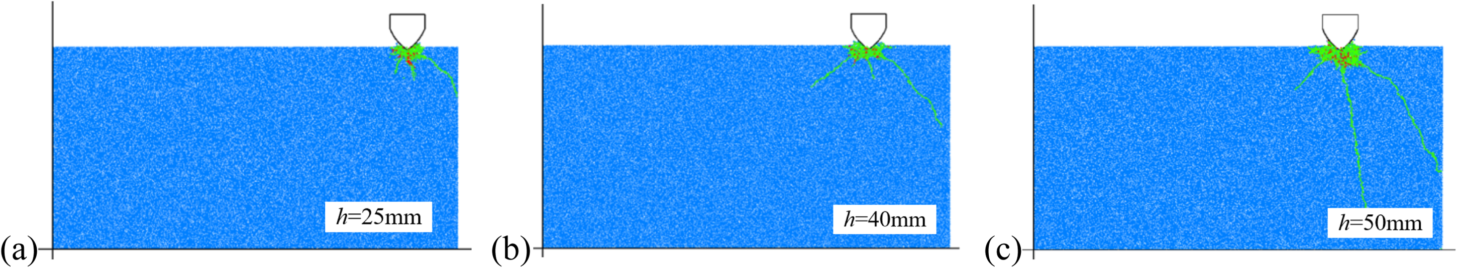
Rock failure diagrams with different cutting thicknesses in simulation: (a) 25 mm, (b) 40 mm, (c) 50 mm.
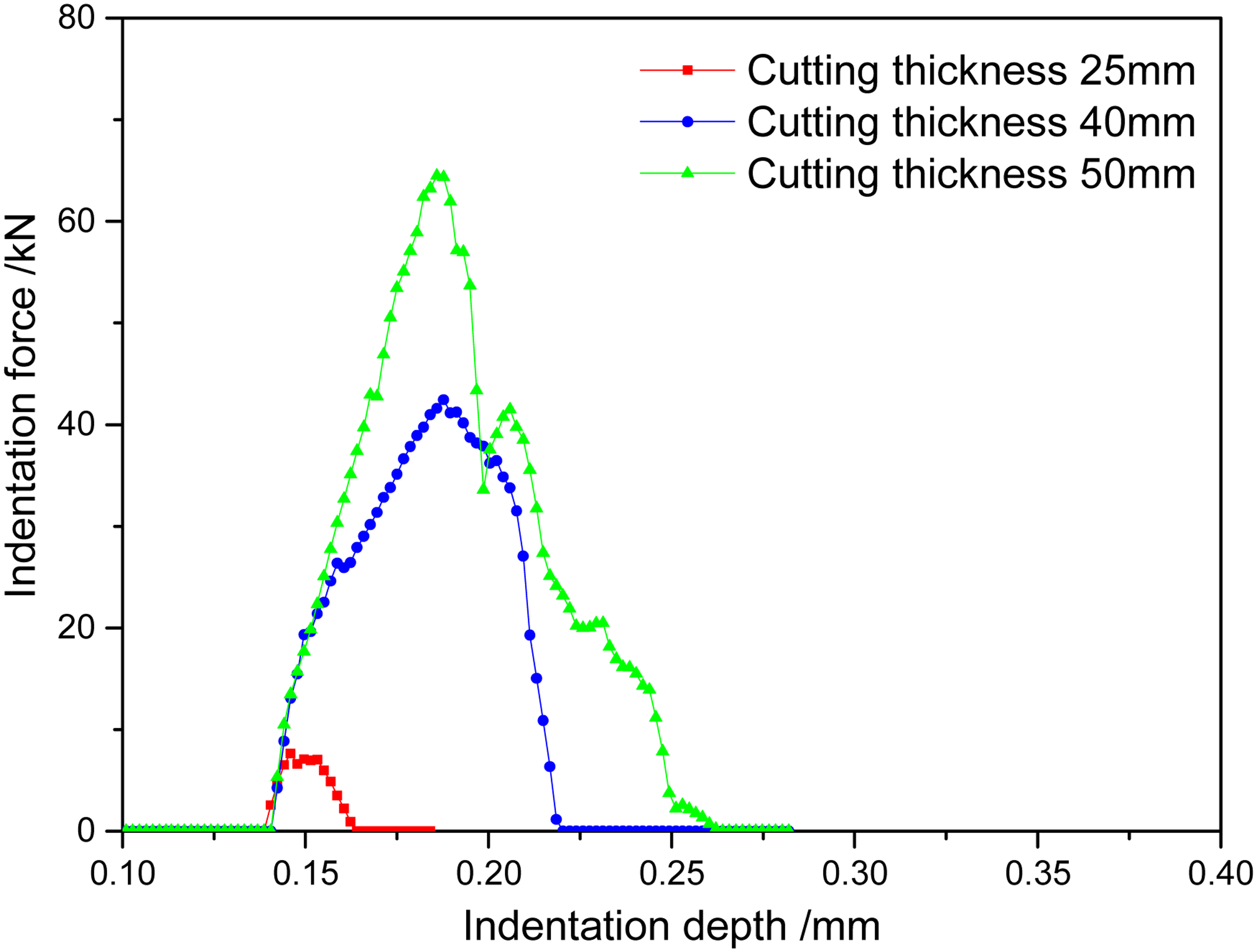
The curves of indentation force with different cutting thicknesses in the simulation.
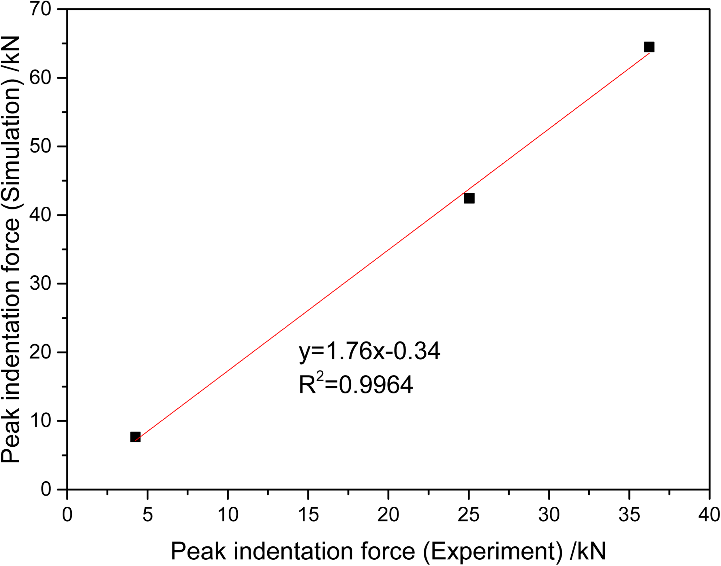
The relationship between peak indentation forces obtained by simulation and experiment.
Result and discussion
Effect of indentation dip angle
Effect of indentation dip angle on rock cracking process
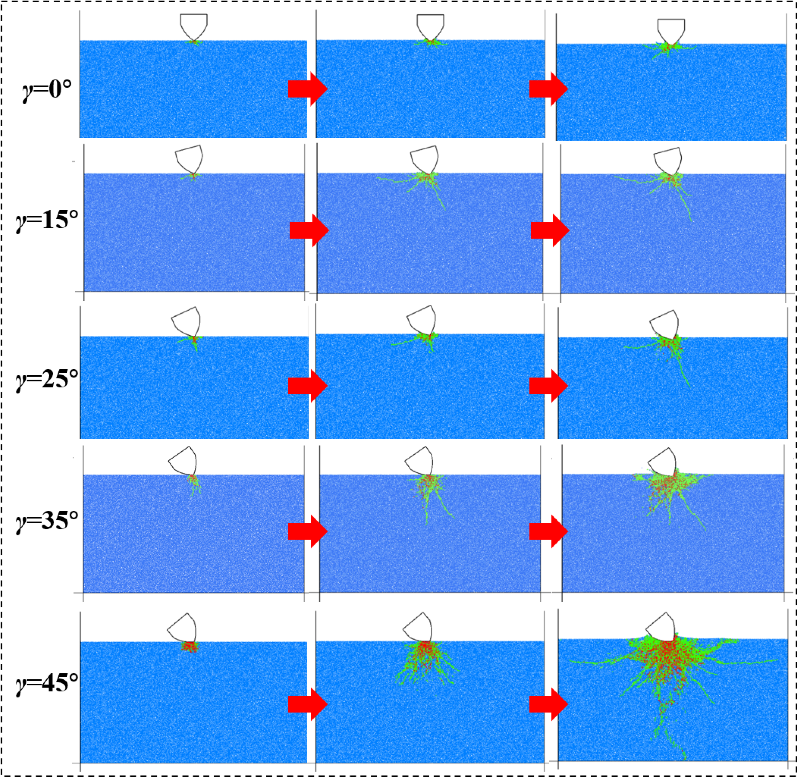
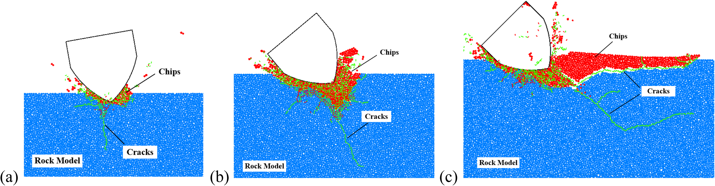
The cracking process of coal with different indentation dip angles is shown in Figure 11. The green lines in these figures are micro tensile fractures, while the red lines are micro shear fractures. When the indentation dip angle is 0°, the stress concentration region is formed firstly beneath the pick tip. With the expansion of the stress concentration region, the initial cracks composed of micro tensile fractures propagate perpendicular to the surface of the pick tip. And then, the macro cracks propagate horizontally toward the free surface, and tiny chips are formed. When the indentation dip angle is 25°, the two main macro cracks are formed, that is, along the axis of the pick and perpendicular to the left side of the pick. The macro crack perpendicular to the pick surface propagates horizontally tending to form large chips. The crack along the axis of the pick propagates towards the interior of the rock, and it's difficult to form rock chips. When the indentation dip angle is 45°, only one side of the pick contacts with the rock, and the stress acts on the rock like a plane stress. With the pick indentation, a large crush zone is formed beneath the pick tip composed of micro shear fractures and propagates downwards.
Crack process of coal with different indentation dip angles.
Figures 11 and 12 show the crack diagrams of coal and red sandstone, respectively, with different indentation dip angles ranging from 0° to 45°. It shows that with the increase of indentation dip angle and constant indentation depth, the area of the crush zone increases for both coal and red sandstone. However, the indentation dip angle has a more significant effect on the crack process of coal. The fracture process of coal and red sandstone is similar when the indentation dip angle is smaller than 35°. Firstly, a small crush zone is formed under the pick tip with some macro cracks. There is one main crack that propagates towards the inside of the rock along the axis of the pick. However, when the indentation dip angle is larger than 35°, the crush zone beneath the pick tip is larger, especially for coal. For breaking coal, the debris is compressed downward resulting in the propagation of macro cracks around the crush zone. However, more macro cracks are initiated and propagate along the axis of pick for red sandstone. As the half-cone angle of the pick of U84-25 is 38°, the pick surface is approximately parallel to the rock. The one side of the pick compresses into the rock rather than the pick tip resulting in the reduction of stress concentration. Hence, the coal with low brittleness is fractured in primarily plastic mode with a large crush zone, while the red sandstone is fractured in primarily brittle mode with more macro cracks and large chips.
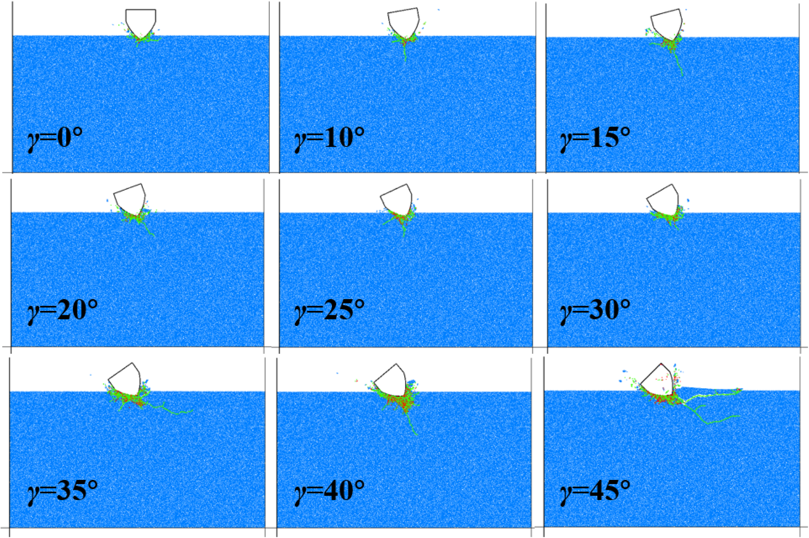
Crack diagrams of red sandstone with different indentation dip angles.
Besides, the number and type of micro fractures are recorded during indentation. Figure 13 shows the relationship between fracture number and indentation dip angle for coal and red sandstone. When crushing coal (Figure 13(a)), with the increase of indentation dip angle, the number of fractures increases exponentially mainly composed of tensile fractures. When the indentation dip angle is larger than 35°, the proportion of shear fractures increases as a larger crush zone is formed. When crushing red sandstone (Figure 13(b)), with the increase of indentation dip angle, the number of fractures increases and tends to be stable. According to the crack diagrams of red sandstone, the size of the crush zone remains constant when the indentation dip angle is larger than 35°, and the rock failed in brittle mode with propagation of tensile fractures. Hence, the number of fractures tends to be stable with the increase of indentation dip angle.
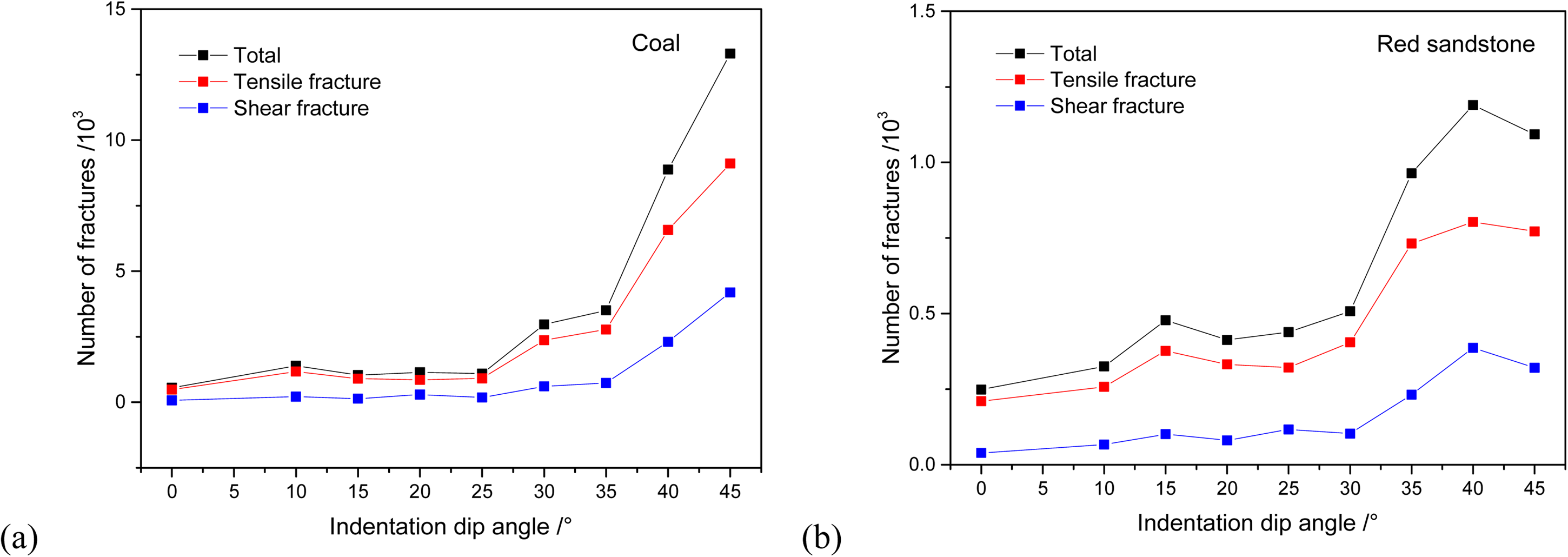
The relationships between fracture number with indentation dip angles: (a) coal and (b) red sandstone.
By comparing the fracture mode and fracture distribution of coal and red sandstone, it can be found that the influence of indentation dip angle on the fracture mechanism of the two rocks is quite different. In the indentation process of coal, due to the low brittleness of coal, a large crushing zone is generated at the pick tip. The particles in the crushing zone will be further squeezed by the pick tip resulting in the formation of macro cracks. As for red sandstone with higher brittleness, only a small crushing zone is formed, which is not enough to reduce the stress concentration acting on the rock beneath the pick tip. Macro cracks are formed along the axis of the pick, and the total number of fractures is far less than that of the coal fracture process.
Effect of indentation dip angle on indentation forces
To analyze the influence of the indentation dip angle on the forces acting on the pick, the mean indentation force and lateral force (Figure 14) are calculated. Figures 15 and 16 show the relationships between mean forces and indentation dip angles in crushing coal and red sandstone, respectively. It can be seen that the average lateral force of the pick increases with the increase of indentation dip angle. The reason is that only one side of the pick tip contacts with the rock in the condition of indentation dip angle not equaling zero. However, when the indentation dip angle is large enough, one side of the pick tip tends to be horizontal resulting in the lateral force tends to be stable. This phenomenon is more significant for red sandstone. Besides, the mean indentation force increases exponentially with the increase of indentation dip angle for both coal and red sandstone due to the expansion of the contact area between the pick tip and rock.
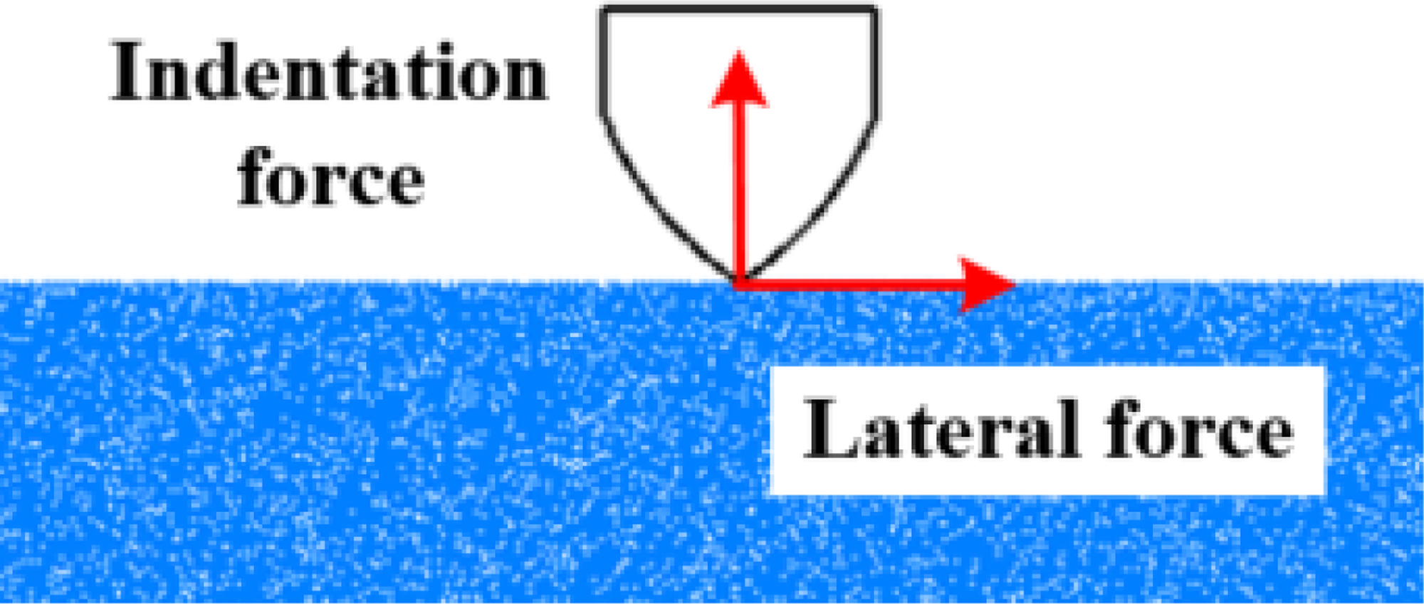
Diagram of intrusive forces in the indentation process.
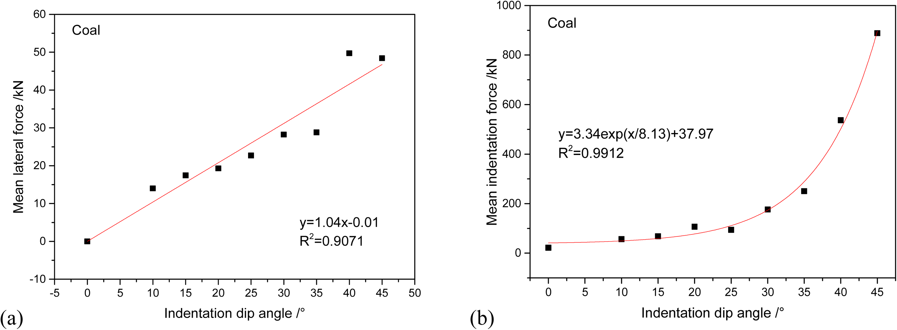
Relationships between mean forces and indentation dip angle during breaking coal.
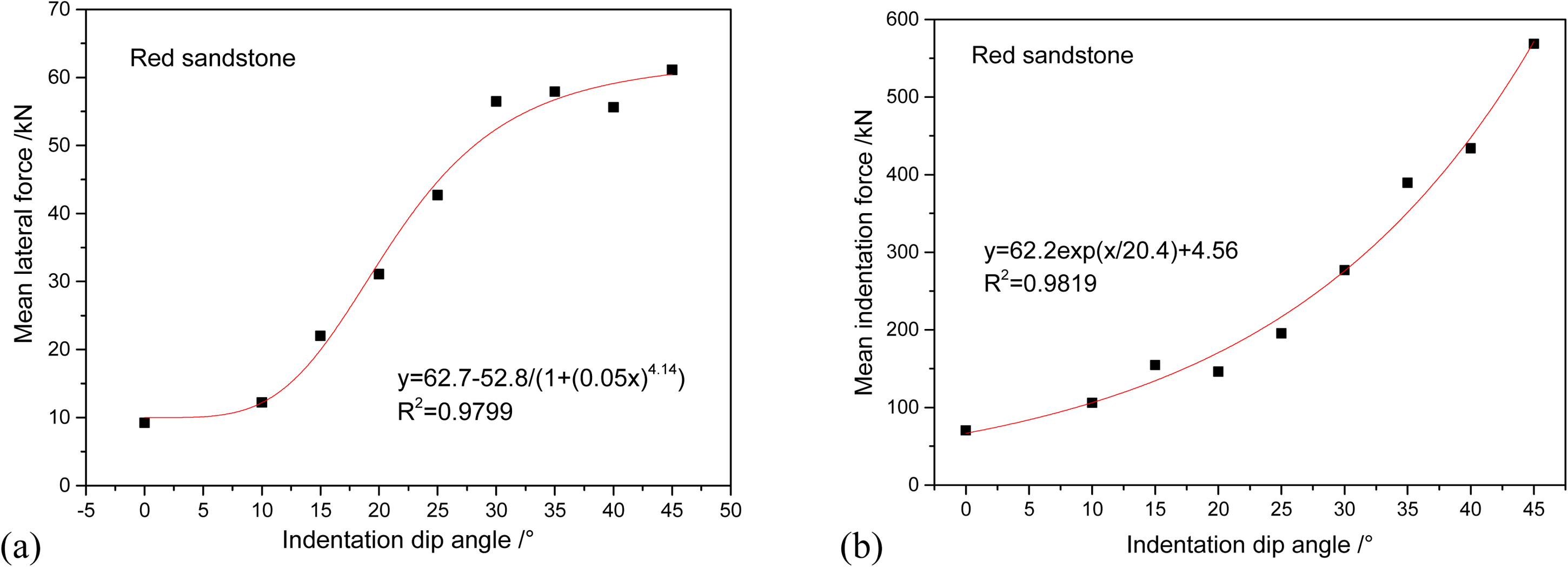
Relationships between mean forces and indentation dip angle during breaking red sandstone.
Effect of indentation dip angle on indentation efficiency
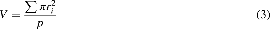
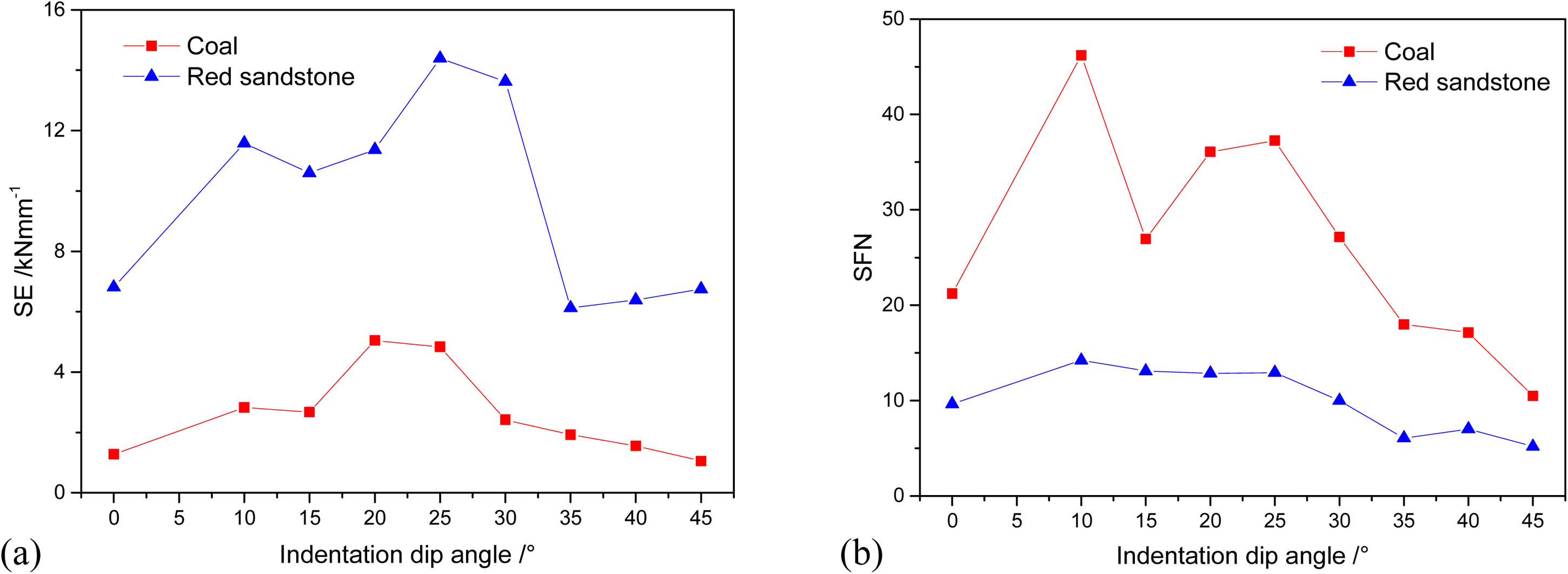
Specific energy (SE) and specific fracture number (SFN) are used to evaluate the indentation performance in different conditions. SE means the energy consumed to crack the unit volume of rock calculated as equation (1). SFN denotes the number of fractures created during cracking the unit volume of rock calculated as equation (2). To calculate SE and SFN, the identification of rock chips in PFC2D based on the displacement of particles is conducted shown in Figure 17 to calculate the chip volume.

Results of chip identification.
Figure 18 shows the relationships between indentation dip angle and SE, SFN. As can be seen in these figures, SE and SFN increase firstly and then decrease for both coal and red sandstone with the increase of indentation dip angle. Firstly, with the increase of indentation dip angle, the crush zone beneath the pick tip expands with the formation of tiny chips, and more energy is consumed in the form of surface energy. When the indentation dip angle is large enough, more macro cracks and large chips are formed resulting in the decrease of SE and SFN.
Relationships between SE, SFN, and indentation dip angle.
Effect of indentation spacing
Effect of indentation spacing on rock cracking process
For investigating the effect of indentation spacing on the rock crack process, two picks are used to impress the rock successively in the simulation. Figure 19 shows the crack diagrams of coal with different indentation spacing. The yellow segments are micro fractures formed by the first pick, and the green segments are micro fractures formed by the second pick. With a constant indentation depth of 3 mm, a large crushing zone is formed by the first pick with some macro cracks. When the indentation spacing is small (s < 16 mm), the indentation process of the second pick is affected by the existing crushing zone, and a large crushing zone is formed beneath the pick tip. However, the macroscopic crack mainly expanded along the existing crack, and no new macro crack was formed. With the increase of indentation spacing (s < 28 mm), the crushing zone of the second pick tends to separate from the existing crushing zone. The macro cracks contacting the two crushing zones are formed, and the rock ridge between the two picks is broken to form large chips. However, the macro cracks are still mainly propagated along the existing cracks. When the indentation spacing is larger (s > 28 mm), the crushing zones of the two picks are separated and connected by new macro cracks. The existing crushing zone has little effect on the indentation process of the second pick. When the indentation spacing is 50 mm, only one macro crack connects the two crushing zones to break the rock ridge between the two picks. Consequently, the indentation spacing of 50 mm is optimal for coal indentation without rock ridges.
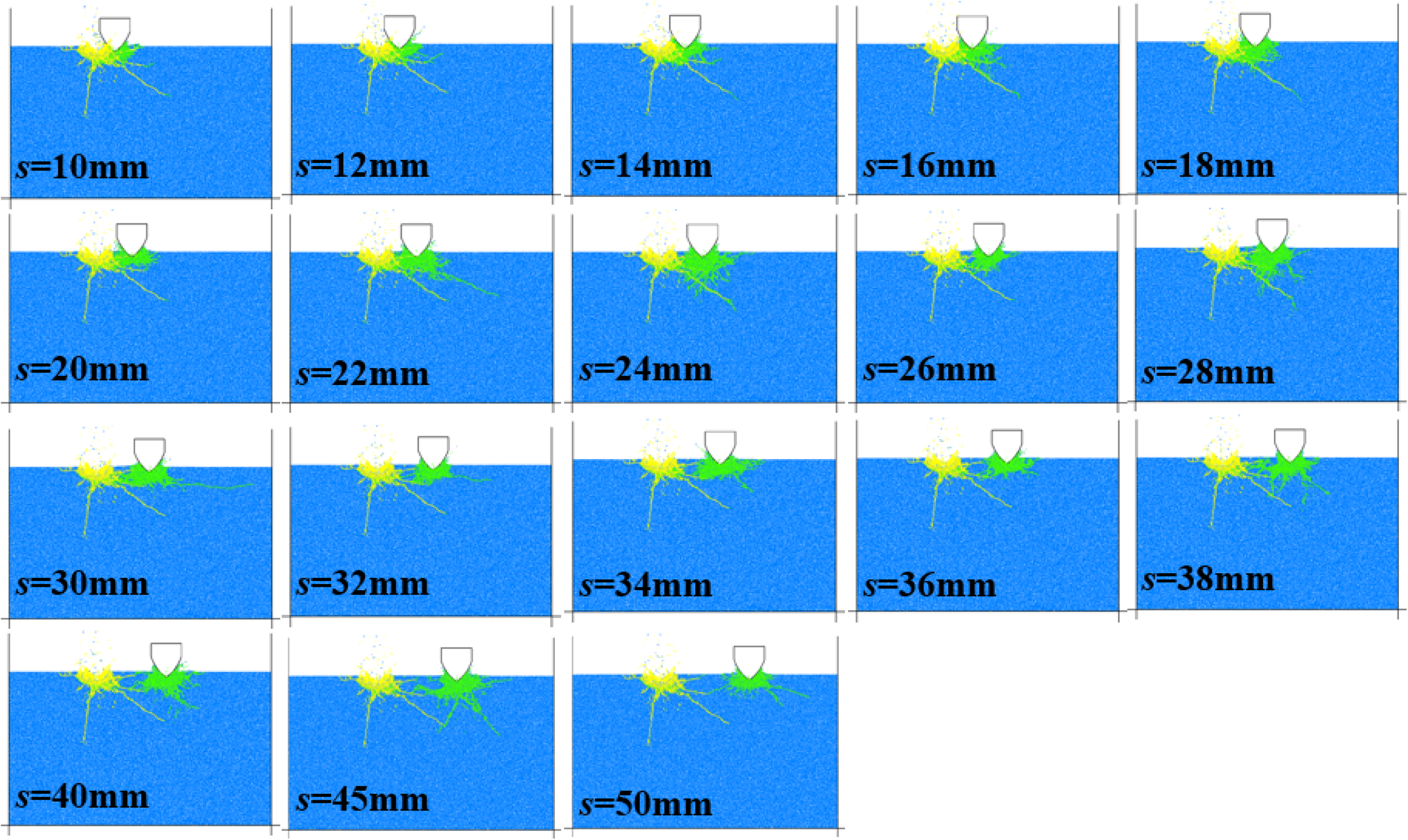
Crack diagrams of coal with different indentation spacing.
As the red sandstone is more brittle, the crushing zone is smaller than that of coal as shown in Figure 20. When the indentation spacing is small (s < 16 mm), the crushing zone of the second pick overlaps with the existing crushing zone, and the macro cracks mainly propagate downward along the existing cracks. With the increase of indentation spacing (s < 40 mm), the crushing zone of the second pick tends to separate from the existing crushing zone. The crushing zones are connected by macro cracks, and the rock ridge between picks is broken to form large chips. When the indentation spacing is larger than 40 mm, the existing crushing zone does not affect the indentation process of the second pick. Therefore, the indentation spacing of 34 mm is optimal for red sandstone indentation with only one macro crack connecting the two crushing zones to break the rock ridge.
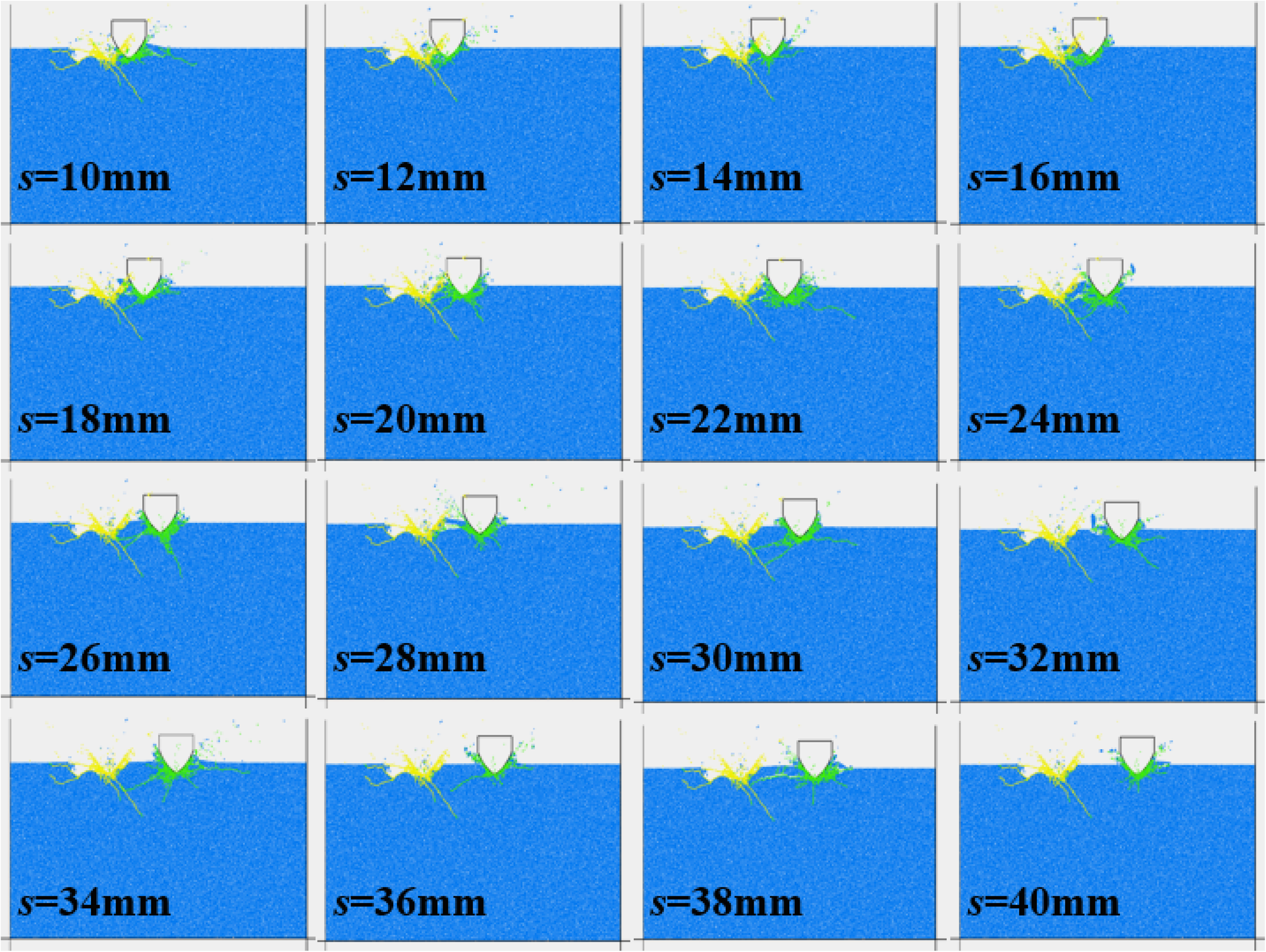
Partial crack diagrams of red sandstone with different indentation spacing.
Besides, in the aspect of the number of micro fractures shown in Figure 21, the relationships between micro fractures and indentation spacing are similar for coal and red sandstone. With the increase of indentation spacing, the number of micro fractures increases firstly and then tends to be stable approximate to the condition of single pick indentation. It's because the existing crushing zone has less effect on the crushing zone of the second pick, and the total crushing zone gets smaller with the increase of indentation spacing. However, the micro fractures formed during coal indentation are more than that of red sandstone with different indentation spacing.
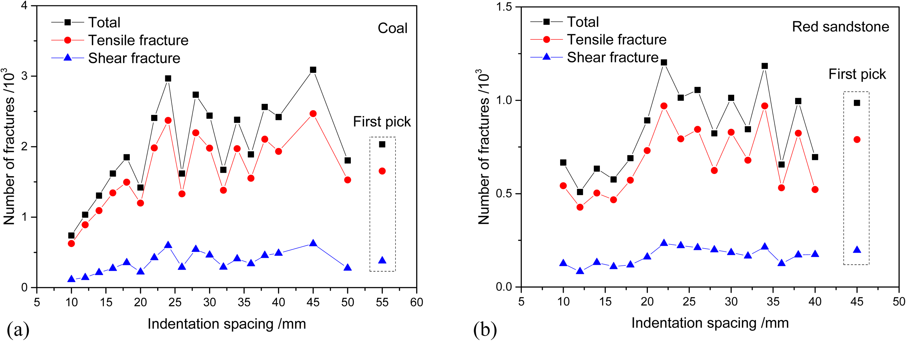
Relationships between micro fractures and indentation spacing of coal and red sandstone.
Effect of indentation spacing on indentation forces
According to Figures 22 and 23, the relationships between the indentation forces of the second pick and indentation spacing are similar for coal and red sandstone. The mean lateral force decreases with the increase of indentation spacing exponentially. With the increase of indentation spacing, the effect of the existing crushing zone has less effect on the indentation process of the second pick resulting in the decrease of lateral force. When the indentation spacing is larger than 30 mm for coal, the lateral force decreases slightly and tends to equal the value of the first pick, while the transition point for red sandstone is about 20 mm. This is because the crushing zone is larger for ductile rock (coal) resulting in the transition point of indentation spacing getting larger. Besides, the mean indentation force increases exponentially with the increase of indentation spacing and tends to be the value of the first pick. The transition point of indentation force for coal is ∼ 20 mm, while the value is about 30 mm for red sandstone.
Relationships between mean forces and indentation spacing during breaking coal.
Relationships between mean forces and indentation spacing during breaking red sandstone.
Effect of indentation spacing on indentation efficiency
In the aspect of indentation efficiency, SE and SFN are calculated shown in Figure 24. It shows that SE and SFN decrease with the increase of indentation spacing firstly, and then tends to be stable for both coal and red sandstone. According to Figures 19 and 20, with the increase of indentation spacing, the crushing zones formed by the two picks are separated, and larger chips are formed resulting in the decrease of SE and SFN. When the indentation spacing is large enough, the effect of the existing crushing zone on chip formation disappears resulting in the increase of SE and SFN for red sandstone with indentation spacing larger than 34 mm. Consequently, the indentation spacing of 50 mm and 34 mm are the optimized spacing for coal and red sandstone, respectively, as SE and SFN are minimal under these conditions. The result is consistent with the analysis of the rock-cracking process above.
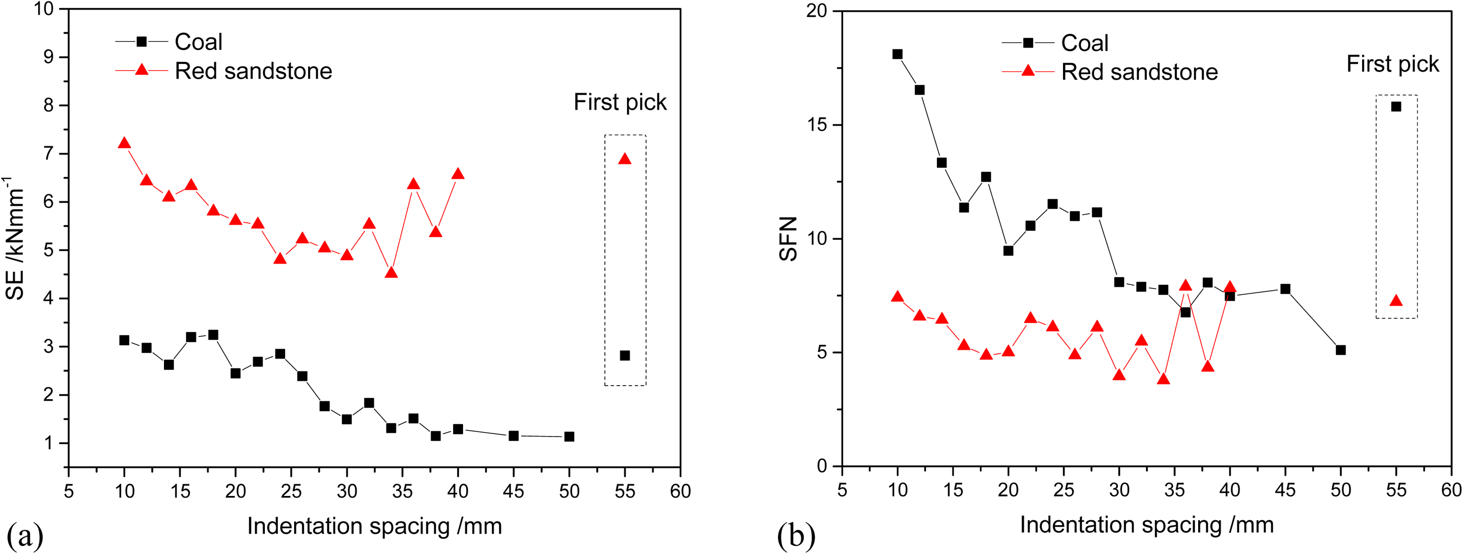
Relationships between SE, SFN, and indentation spacing.
Effect of confining pressure
The preparation of the rock indentation model is shown in Figure 25. Firstly, the biaxial confining pressures are loaded on the rock model by controlling the surrounding walls with a servo algorithm (Figure 25(a)). Then, the upward wall is deleted to provide a free surface for indentation. Meanwhile, the lateral confining pressure remains consistent (Figure 25(b)). Figure 25(c) shows the curves of confining pressures recorded during rock model preparation and rock indentation with a confining pressure of 20 MPa. It is separated into three stages, that is, the loading stage, the stabilization stage, and the indentation stage. In the loading stage, the confining pressure increases stepwise with the surrounding walls moving toward the rock. In the stabilization stage, the vertical confining pressure is unloaded with the deletion of the upper wall resulting in the decrease of lateral confining pressure. Then, the lateral confining pressure is stabilized to the target confining pressure again by the servo algorithm. Meanwhile, the lateral confining pressure remains consistent during rock indentation. Consequently, it is reasonable to investigate the influence of confining pressure on the rock indentation process using this model.
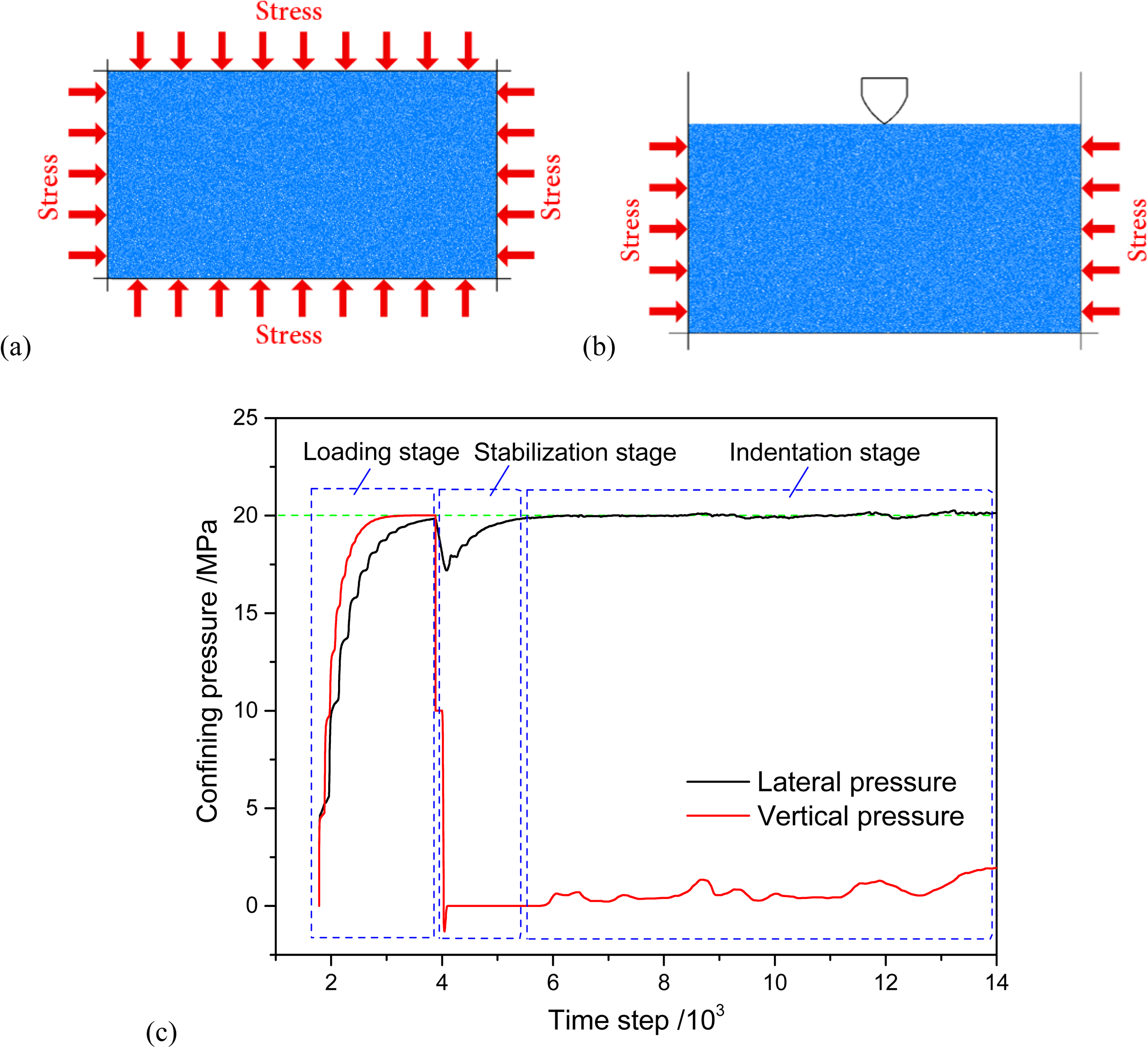
Rock model for indentation under confining pressure: (a) loading confining pressure, (b) rock indentation model, and (c) curves of confining pressures during rock model preparation and rock indentation.
Effect of confining pressure on rock cracking process
Figure 26 shows the crack diagrams of coal under different confining pressures. In the condition of 0 MPa, the crushing zone is formed beneath the pick tip, and macro cracks are generated and propagate vertically. When the confining pressure is low (P ≤ 3 MPa), crushing zones are formed beneath the pick tip. But few macro cracks are generated and propagate horizontally. With the increase of confining pressure (3 MPa < P ≤ 7 MPa), the crushing zones decrease, and no macro cracks are generated. When the confining pressure is higher than 8 MPa (the half of UCS of coal), the rock model is crushed integrally due to the indentation process and confining pressure. For red sandstone, confining pressure has a similar influence on the rock-breaking process shown in Figure 27. When the confining pressure is higher than 25 MPa, only a small crushing zone is formed beneath the pick tip, and the vertical and horizontal macro cracks are limited. When the confining pressure is higher than 40 MPa (about the half of UCS of red sandstone), the rock model is crushed to failure due to the indentation process and confining pressure. Consequently, confining pressure has a similar influence on rock failure for ductile or brittle rocks. Confining pressure can strengthen the rock by increasing the horizontal internal stress which results in the limitation of the generation of macro cracks, especially vertical cracks. And it's harder to form large chips without macro crack propagation. Besides, when the confining pressure exceeds the half of UCS of rocks, the rock block will fail integrally due to the stress disturbance during the indentation process and confining pressure. This phenomenon is of great significance for artificially induced rock crushing using confining pressure to improve the efficiency of hard rock mining.
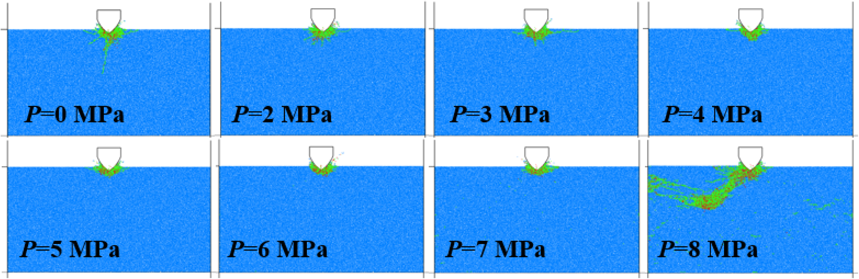
Crack diagrams of coal under different confining pressures.
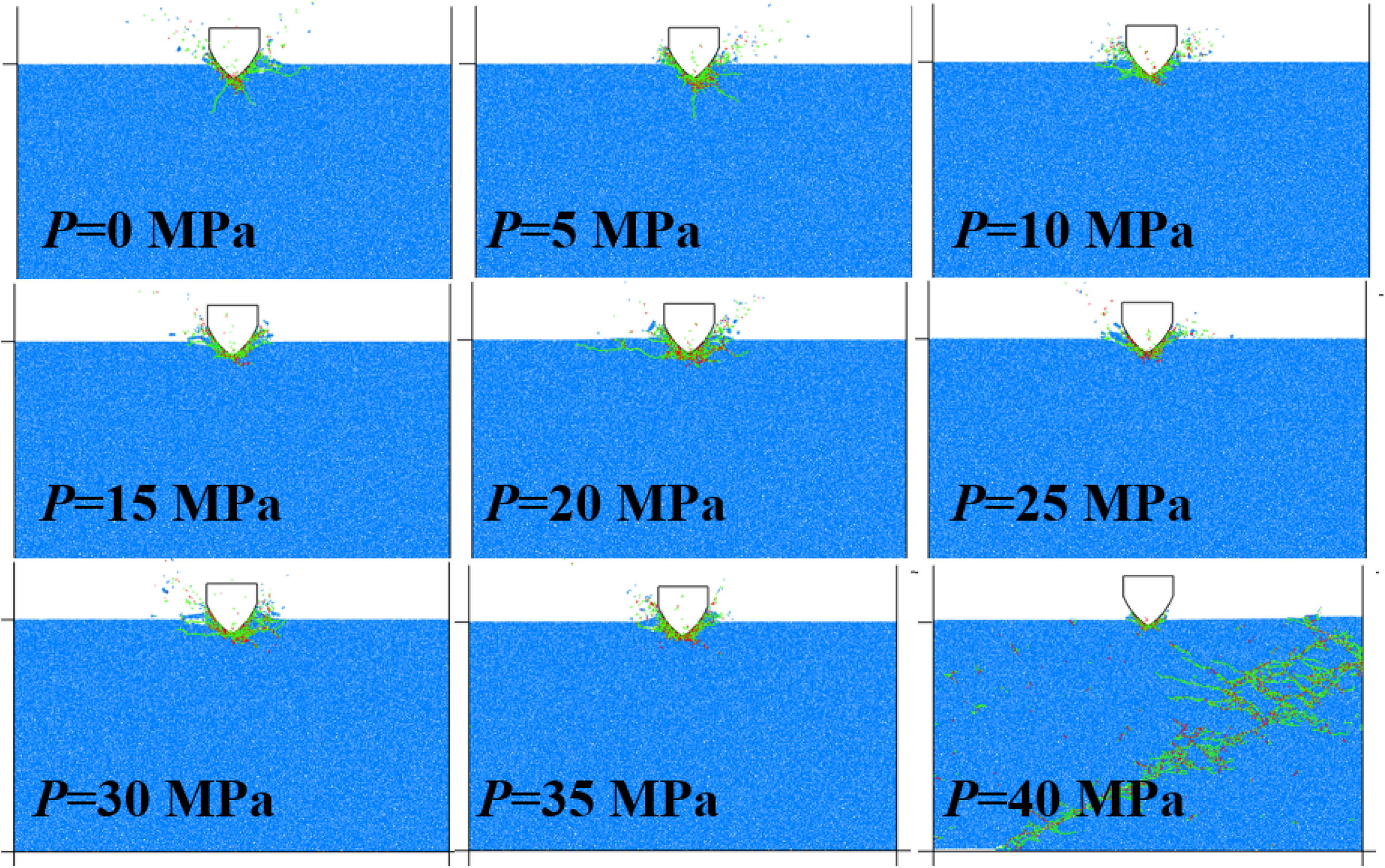
Crack diagrams of red sandstone with different confining pressures.
Besides, the influence of confining pressure on the number of micro fractures during the indentation process is shown in Figure 28. For coal, the number of micro fractures decreases with the increase of confining pressure due to the reduction of crushing zones, and the limitation of generation and propagation of macro cracks. For red sandstone, confining pressure has less effect on the number of micro fractures as the crushing zone of brittle rocks is smaller, and micro fractures mainly distribute in the crushing zone.
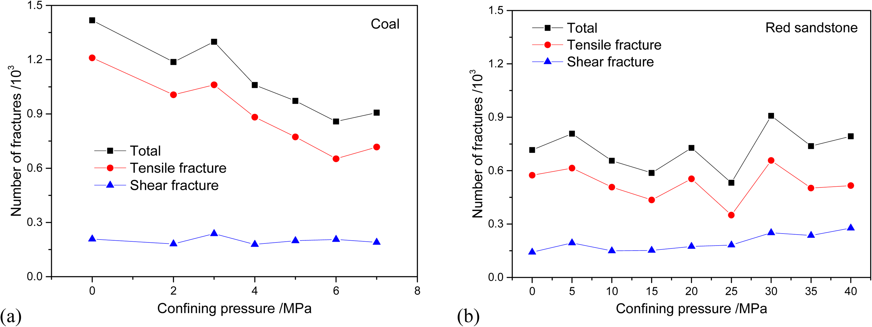
Relationships between micro fractures and confining pressure: (a) coal and (b) red sandstone.
Effect of confining pressure on indentation forces
Figures 29 and 30 show the relationships between confining pressure and indentation forces of coal and red sandstone. For coal, the mean lateral force decreases and tends to be 0 with the increase of confining pressure (Figure 29(a)). The reason is that a semicircular crushing zone is formed in the condition of high confining pressure resulting in the forces acting on both sides of the pick tip being uniform. However, for red sandstone, confining pressure has less effect on the lateral force due to the crushing zone being small and asymmetric (Figure 30(a)). The indentation force during breaking coal decreases firstly and then increases rapidly with the increase of confining pressure (Figure 29(b)), while it increases linearly during breaking red sandstone (Figure 30(b)). When the confining pressure is low, the confining pressure weakens the strength of coal approaching the free surface. The indentation force is reduced under the coupling effect of indentation and confining pressure. When the confining pressure is high, the coal is compressed to be denser which resulting in the increase of indentation force. However, as the strength and brittleness of the red sandstone are much higher than coal, the confining pressure does not weaken the red sandstone, but strengthen it, which resulting in the linear increase of indentation force.
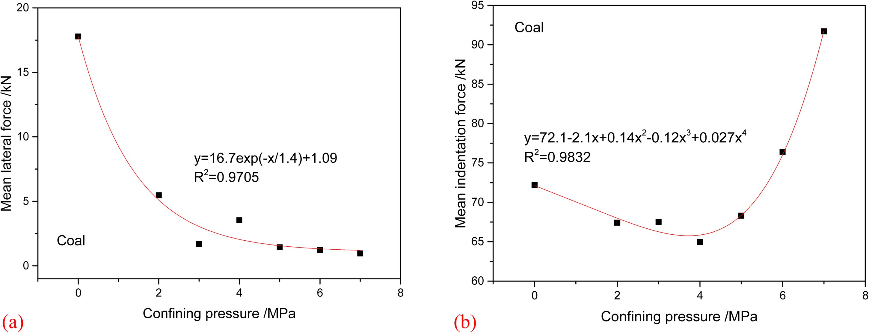
Relationships between mean forces and confining pressure during breaking coal.
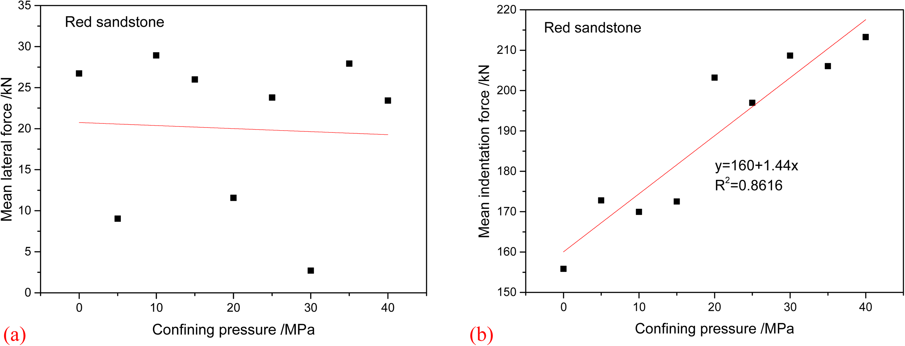
Relationships between mean forces and confining pressure during breaking red sandstone.
Effect of confining pressure on indentation efficiency
SE and SFN under different confining pressures are calculated shown as in Figure 31. With the increase of confining pressure, SE increases slowly (Figure 31(a)) due to the increase of indentation force and reduction of large chips for both coal and red sandstone. Besides, SE for breaking red sandstone is higher than that for breaking coal as the strength of red sandstone is higher. Moreover, with the increase of confining pressure, SFN is higher and increases to be stable for coal (Figure 31(b)) while confining pressure has less effect on SFN for breaking red sandstone. Consequently, the confining pressure will reduce the cutting efficiency and particle size during rock cracking.
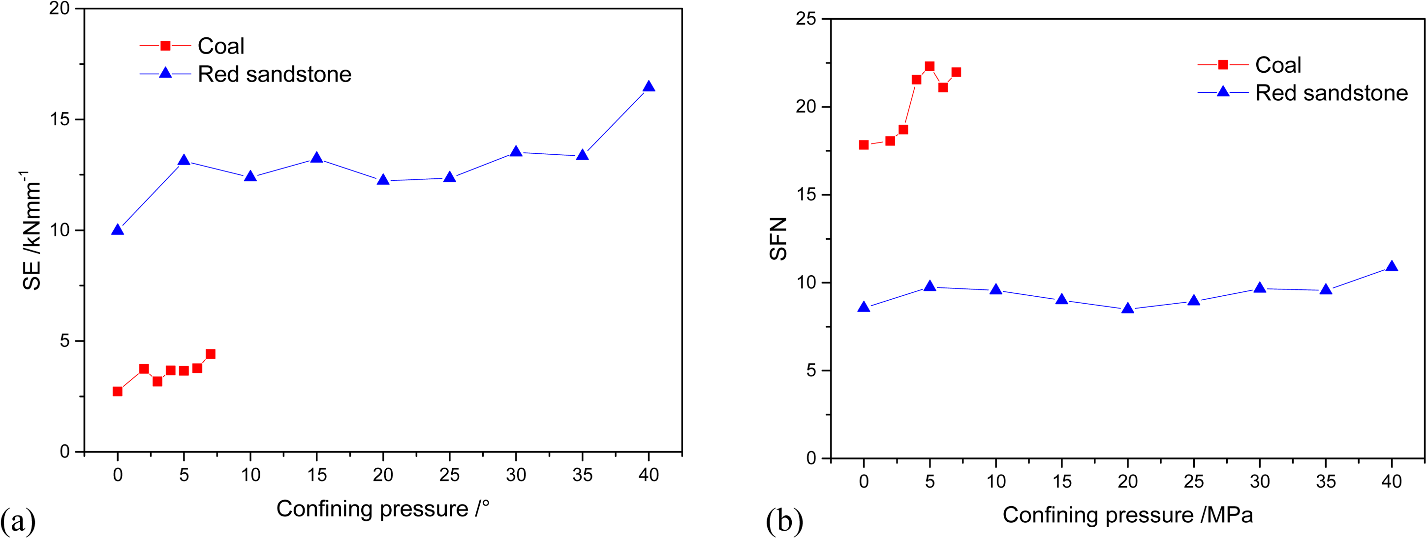
Relationships between SE, SFN, and confining pressure.
Conclusion
In this article, the simulation of rock indentation is conducted by the discrete element method to study the influence of indentation dip angle, indentation spacing, and confining pressure on the rock cracking process. The results and conclusions are obtained as follows:
The crushing zone expands with the increase of the indentation dip angle of the pick due to the increase of contact surface between the pick and rock. The macro cracks mainly propagate along the axis of the pick. The coal with low brittleness is cracked in primarily plastic mode with a large crushing zone, while the red sandstone is cracked in primarily brittle mode with more macro cracks and large chips. In terms of indentation loads, both the mean lateral force and mean indentation force of the pick increase with the increase of indentation dip angle. With the increase of indentation spacing, the influence of the existing crushing zone on the indentation process of the second pick reduces. In addition, the mean indentation force increases, and the mean lateral force decreases with the increase of indentation spacing. Besides, the indentation spacing of 50 mm and 34 mm are the optimized spacing for coal and red sandstone with the lowest specific energy, respectively. Confining pressure has a similar influence on rock failure for ductile or brittle rocks. The confining pressure can strengthen the rock by increasing the horizontal internal stress which results in the limitation of the generation of macro cracks, especially vertical cracks. When confining pressure exceeds the half of UCS of rocks, the rock block will fail integrally due to the stress disturbance during the indentation process and confining pressure. Besides, with the increase of confining pressure, the mean lateral force decreases while the mean indentation force and specific energy increase.
Footnotes
Acknowledgements
This research was supported by the National Natural Science Foundation of China (51874279) and the talent introduction project of Nanjing Vocational University of Industry Technology (YK21-01-04).
Declaration of conflicting interests
The author(s) declared no potential conflicts of interest with respect to the research, authorship, and/or publication of this article.
Funding
The author(s) disclosed receipt of the following financial support for the research, authorship, and/or publication of this article: This work was supported by the talent introduction project of the Nanjing Vocational University of Industry Technology, National Natural Science Foundation of China (grant numbers YK21-01-04 and 51874279).