
Abstract
Energy auditing is crucial for both emerging and developed nations, focusing on aspects such as energy efficiency, quality and intensity. This becomes especially significant in the industrial sector, where major operating costs involve materials, machinery, personnel and energy. A key objective is identifying energy consumption in the Continuous Miner Machine, boasting a 1050 KW connected load, to explore opportunities for energy savings and improved quality. The execution of an energy audit promises increased efficiency, enhanced power quality, reduced costs and prevention of energy wastage. This research study has meticulously examined the electrical equipment supplying power to Continuous Miner Machines, proposing modifications to boost production through energy-efficient methods. Comprehensive assessments of primary substations, including Incomers, Transformers, Feeders, etc., involve tests for voltage, current, power factor, harmonics and AC waveform. Thermal imaging is employed to analyze the operational temperature of the electrical equipment. The graphical representations of test outcomes have highlighted a significant recommendation: installing an Automatic Power Factor Controller on the inductive load side of transformers could lead to a notable 3.85% reduction in energy costs.
Introduction
Energy availability is essential to all economies. Energy is becoming increasingly crucial for people, businesses and entire countries as industrialize, expand and depend on more complex infrastructure and technology systems. Enhancing energy efficiency at business, regional, national and international levels becoming increasingly popular on a global scale. It is seen to address worries about energy security and the environmental effect of energy consumption. ‘Improvements in final consumption efficiency offer the greatest opportunity to solve energy security, pricing and environmental issues’, says the G8 Clean Energy and Development Report. Energy efficiency is widely recognized as a lucrative business model that can provide multiple non-energy benefits without the need for subsidies. These benefits include increased productivity, increased employment, reduced fuel shortages and improved public health. These benefits were recently recognized because of a landmark International Energy Agency study. (Fawkes et al., 2016) The need for auditing and transitioning energy consumption is crucial because it has the potential to reduce dependence on fossil fuels, thereby lessening the negative environmental effects associated with these pollutants (Kreith and Goswami, 2007; Mahdi, 2018).
As industry consumes the most energy, improving energy efficiency in industry is key to reducing carbon emissions (Thollander and Palm, 2012). Coal India is the world's largest coal producer. Coal was mined by both open pit and underground mining. Most of the coal consumed in India is used to generate electricity in thermal power plants. Energy cost reductions are achieved using energy-efficient technologies, energy carrier conversion, demand response and more energy-efficient operation. An energy audit is a valuable tool in removing barriers to energy efficiency. Additionally, a properly structured initial energy audit is the first critical step in establishing a successful internal energy management program in your industry (Rosenqvist et al., 2012).
This research aims to enhance our understanding of electrical equipment performance in heavy mines machinery through a unique application of energy audit tools. Unlike existing studies that focus on energy efficiency in various domains, this research sheds light on the overlooked dynamics of mines machinery and its electrical components. Using innovative methods such as Harmonics and Thermal imaging, the study delves into nuanced analyses of energy wastage, aiming to provide specific recommendations for improvement. By filling these unexplored gaps, the research aspires to be a catalyst for transformative enhancements in the energy efficiency of heavy subterranean machinery, contributing to a more sustainable and productive future for the mining industry.
Coal is produced in the Khairaha Underground mines using Board and Pillar mining methods (Siddiqui et al., 2022a). Coal mining operations use continuous miner to remove coal reserves from underground coal seams. The miner consists of a rotating steel drum fitted with tungsten carbide picks that scrape coal from seams (Bogunovic et al., 2009; Mendis and Perera, 2006; Siddiqui et al., 2022b). The continuous miner should also have a roof and bolter attached. However, these elements should not prevent construction personnel from placing support pattern rows. Continuous miner systems enhance the speed of coal mining operations while reducing the need for extensive blasting. Moreover, these machines enable meeting the growing demand for underground coal production, as illustrated in Figure 1.
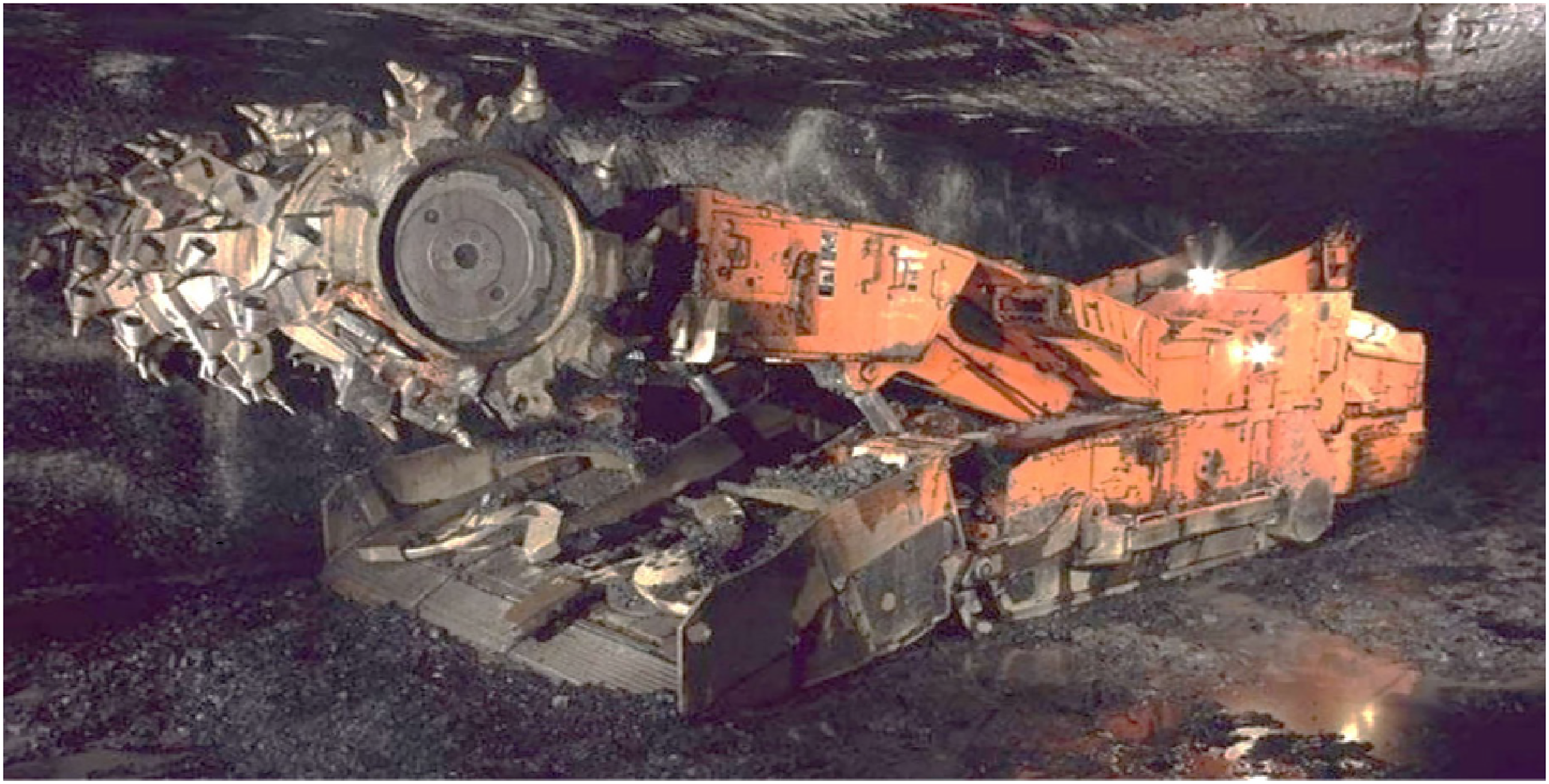
Continuous miner machine at underground.
Cut coal transported by battery-driven Shuttle Car up to the in-pit crusher, roof support is done by Twin Bolter, and coal from the in-pit coal crusher is brought to the surface bunkers by belt conveyors. There are other machines rather than coal production, such as LHD, Pumps, Main Mechanical Ventilators and haulages, for allied mining processes (Siddiqui et al., 2022b). All these machines are powered by electricity. Electricity consumption is critical for the functioning of these machines, which use a significant portion of overall expenses.
A large electrical substation, 33KV/3.3KV, has been installed at the surface to handle all the mine's loads. In this article, a complete investigation of the substation's apparatuses was undertaken, and improvement strategies to increase production through energy-efficient techniques were proposed. A year's worth of detailed data, including output, was collected from April 2021 to March 2022. The electricity bill for the same period was gathered, as well as unit consumptions, contact demand, billing demand, power factor, power factor rebate or surcharge, time of day (TOD) surcharge, rebate and load factor, particular energy usage and so on.
The transformers’ performance was evaluated. Its power quality and load factor profile were examined, and graphs were generated. Based on real data obtained with a Portable Power Analyzer, voltage and current, power and power factor, voltage and current harmonics and AC waveform profiles have been shown. The working efficiency of the transformers was compared to their maximum efficiency. The harmonics analysis was conducted, and the resulting graph illustrates harmonic distortion in both power and distribution transformers. The graph compares the actual harmonic distortion (I-THD) during operation with the acceptable limits. Additionally, it displays harmonics profiles and sinusoidal waveforms, utilizing real data collected by the Portable Power Analyzer shown in Figure 2.
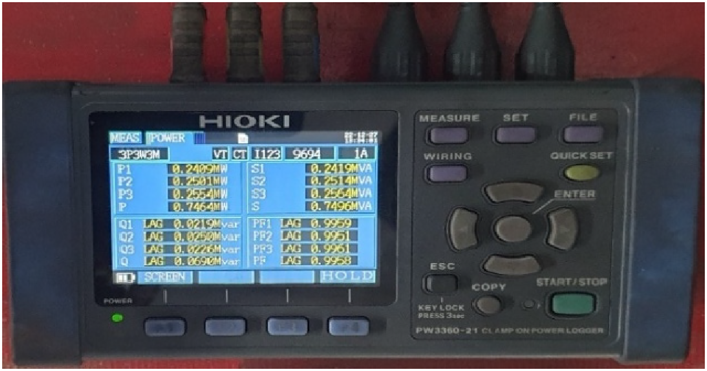
Portable power quality analyser.
Thermal Imaging Camera, as shown in Figure 3, utilized to take thermal photos of the transformers and their associated circuits. The analysis of these images focused on identifying any thermal distortion in the devices.
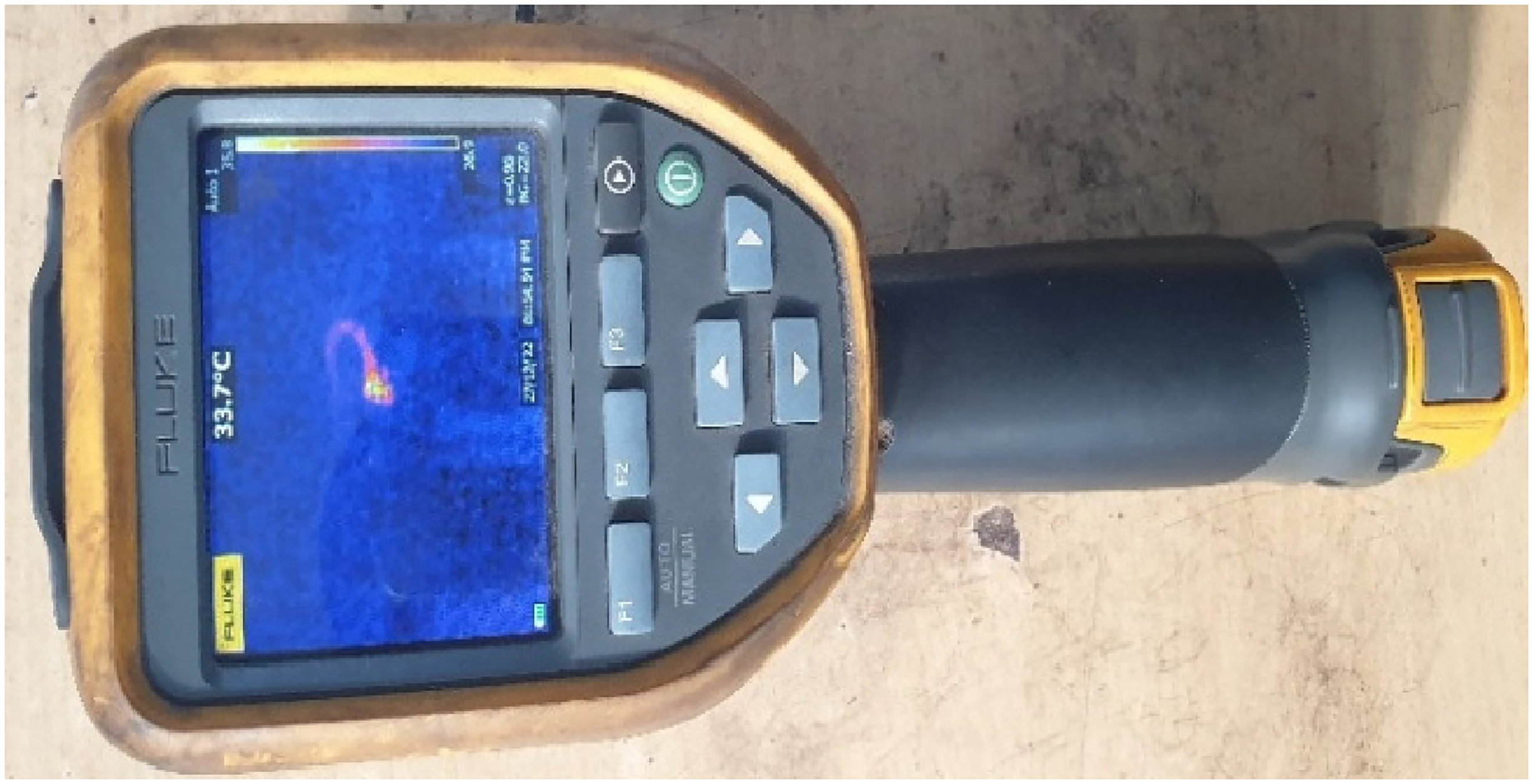
Thermal imaging camera.
Literature review
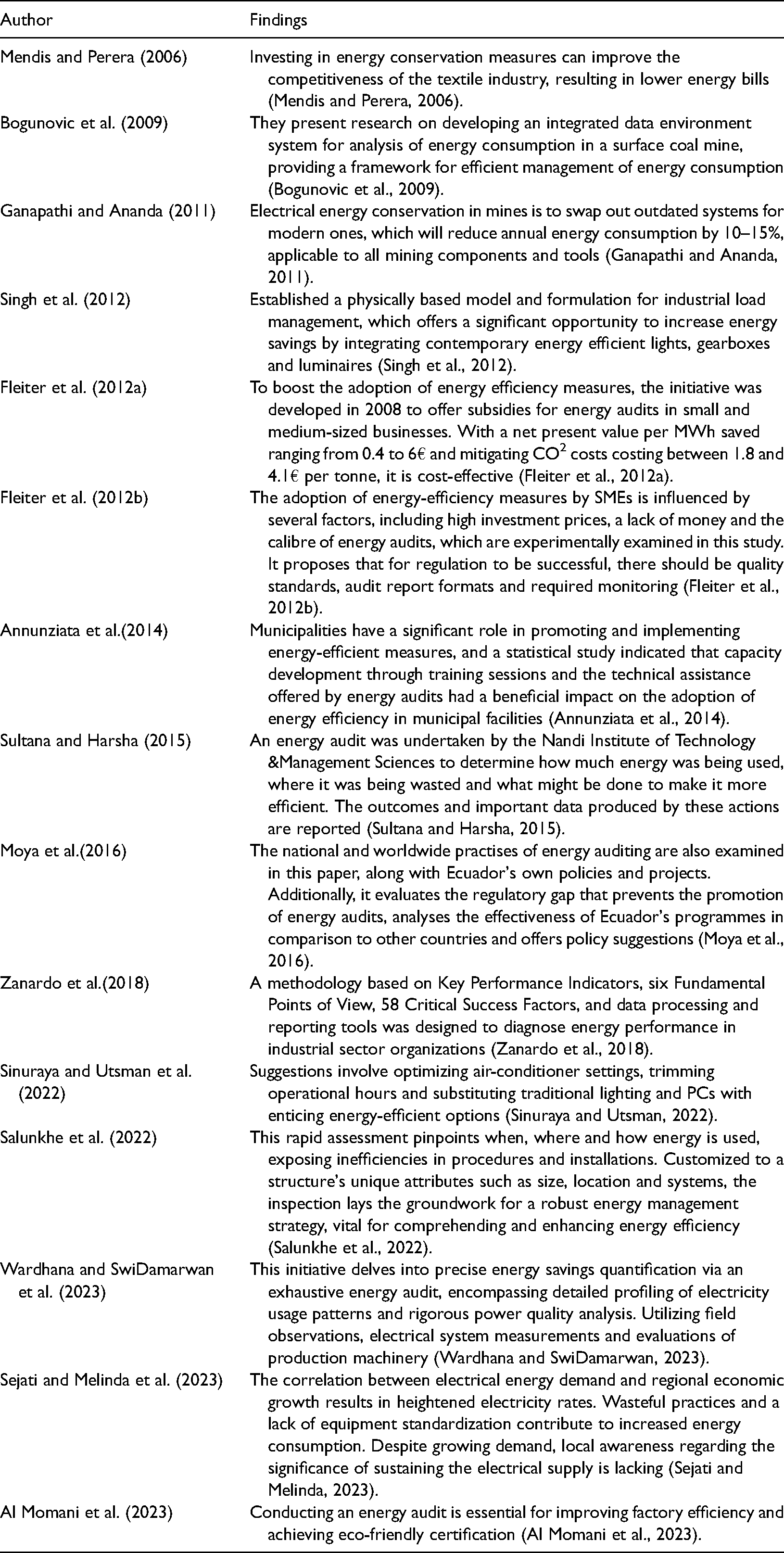
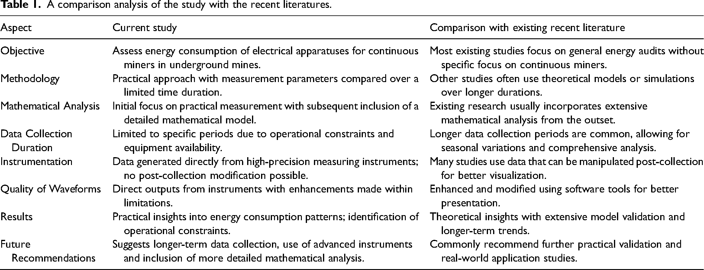
A detailed comparison of the referenced literature with the present study is thoroughly discussed in Table 1.
A comparison analysis of the study with the recent literatures.
Methodology
The energy audit study employed a specific methodology, which was systematically implemented in several steps, visually presented in Figures 4–6.
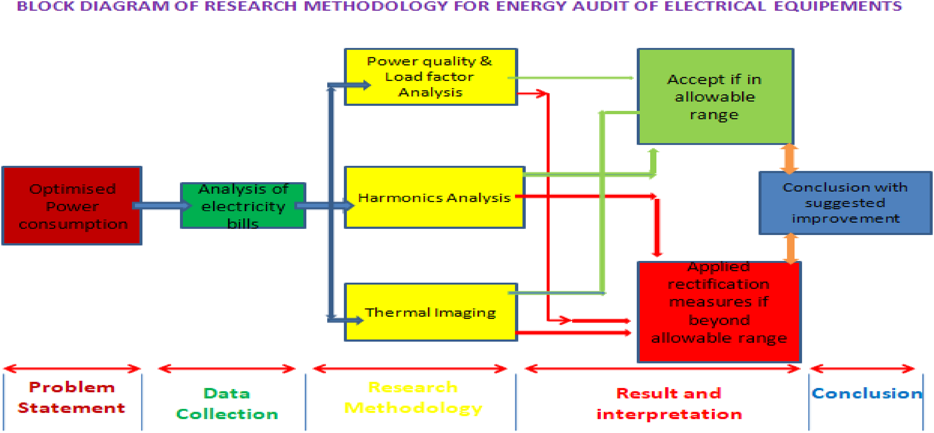
Research methodology block diagram.
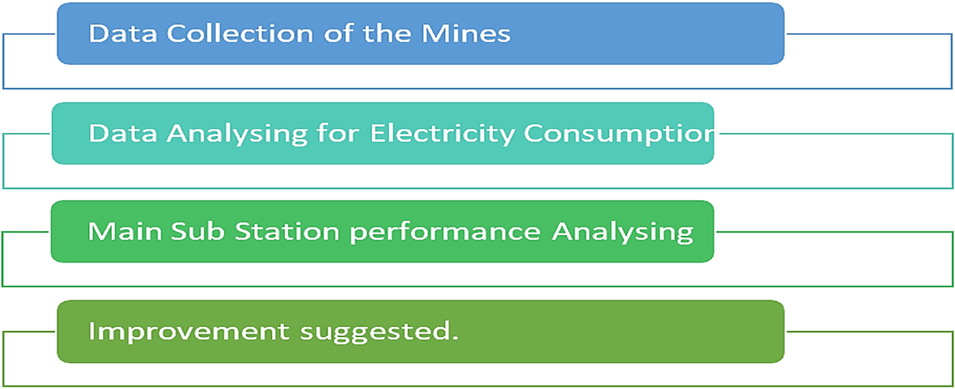
Methodology adopted during energy audit of the mines.
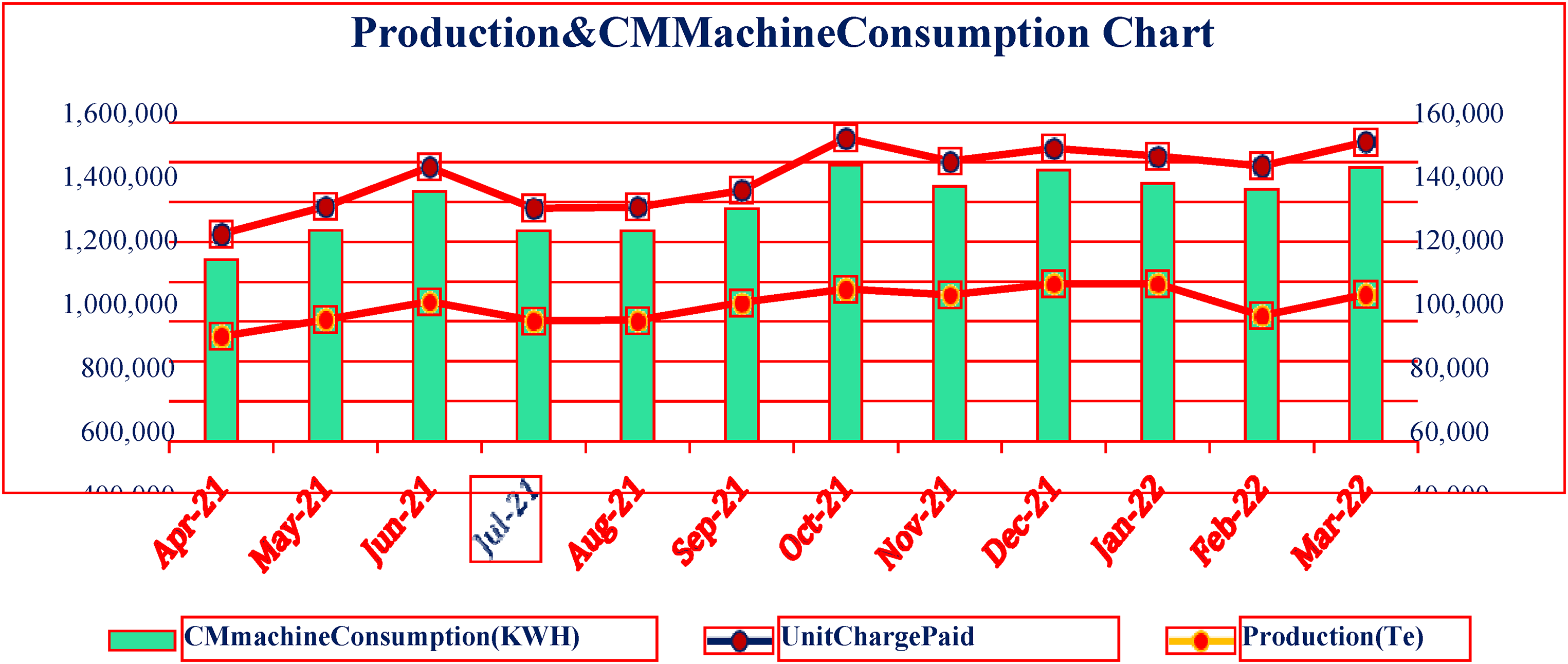
Graph of month wise production.
Data collection
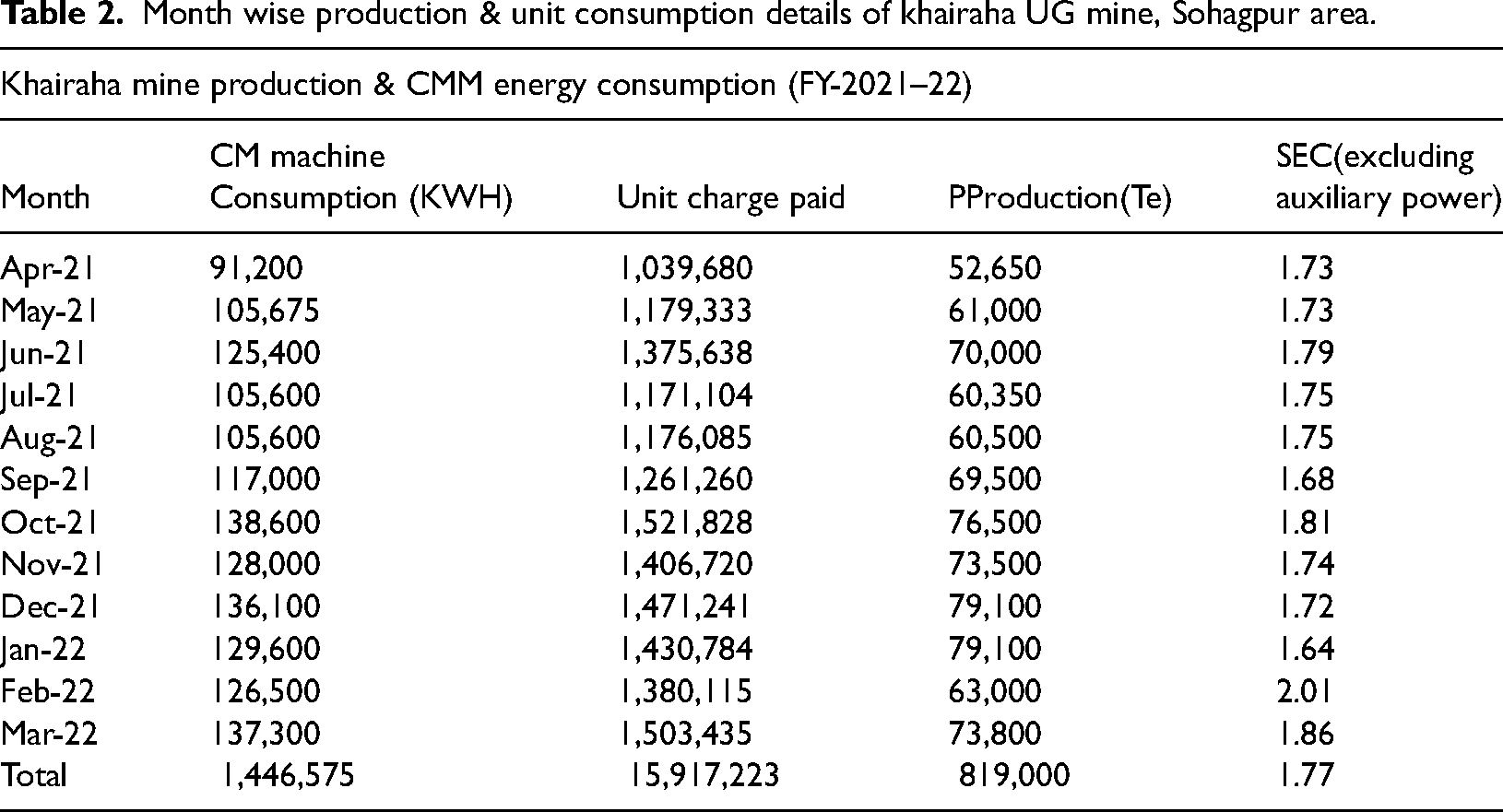
To assess power quality and efficiency, we collected data on production, unit consumption and SEC (Specific Energy Consumption) for a year from April 21 to March 22. The results of this analysis are presented in Figures 5 and 6.
The summarized information presented in Table 2 is derived from a meticulous analysis of the electricity bill data specifically associated with the Khairaha Underground (UG) mine.:
Month wise production & unit consumption details of khairaha UG mine, Sohagpur area.
Data analysis
Power factor, contract demand (CD), highest recorded demand, connection type and electricity pricing structure have all been investigated in recent months. The power bills were gathered and evaluated to identify the various charges assessed as well as any rebates or penalties incurred while the unit was in service. Table 3 provides a breakdown of the power usage pattern spanning from December 2021 to November 2022. Based on last one year electricity bill, mentioned in Table 2, it has been observed that energy consumption (kWh) was maximum during June-2022 and minimum during March-2022. The energy cost paid was maximum during June 2022 and minimum during March-2022.
Electricity bill analysis of khairaha UG mine.
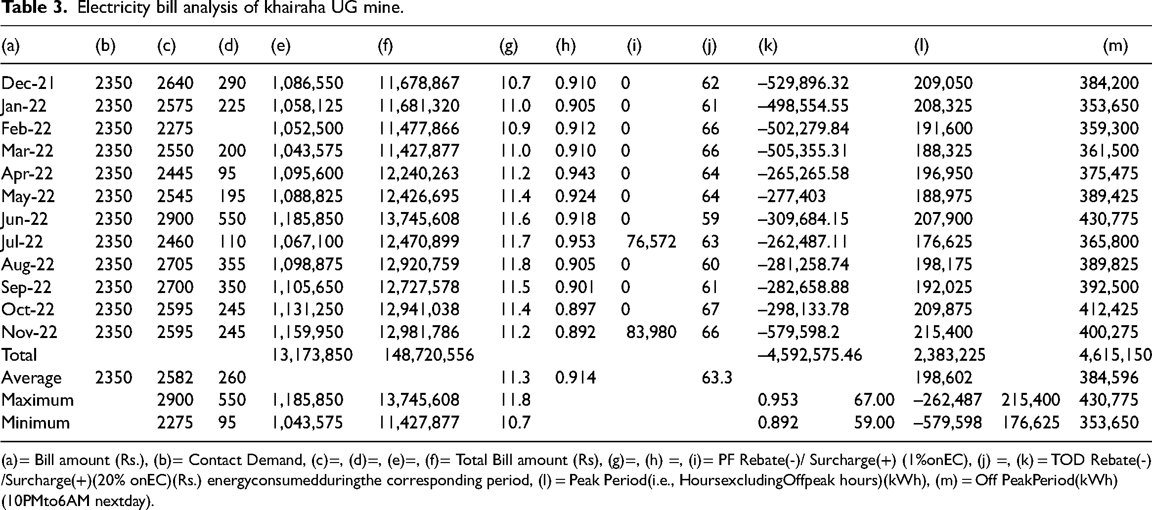
(a)= Bill amount (Rs.), (b)= Contact Demand, (c)=, (d)=, (e)=, (f)= Total Bill amount (Rs), (g)=, (h) =, (i)= PF Rebate(-)/ Surcharge(+) (1%onEC), (j) =, (k) = TOD Rebate(-) /Surcharge(+)(20% onEC)(Rs.) energyconsumedduringthe corresponding period, (l) = Peak Period(i.e., HoursexcludingOffpeak hours)(kWh), (m) = Off PeakPeriod(kWh) (10PMto6AM nextday).
The energy consumption in kilowatt-hours (kWh) and the corresponding payment patterns for each month from December 2021 to November 2022 at the mine are visually represented in Figure 7.
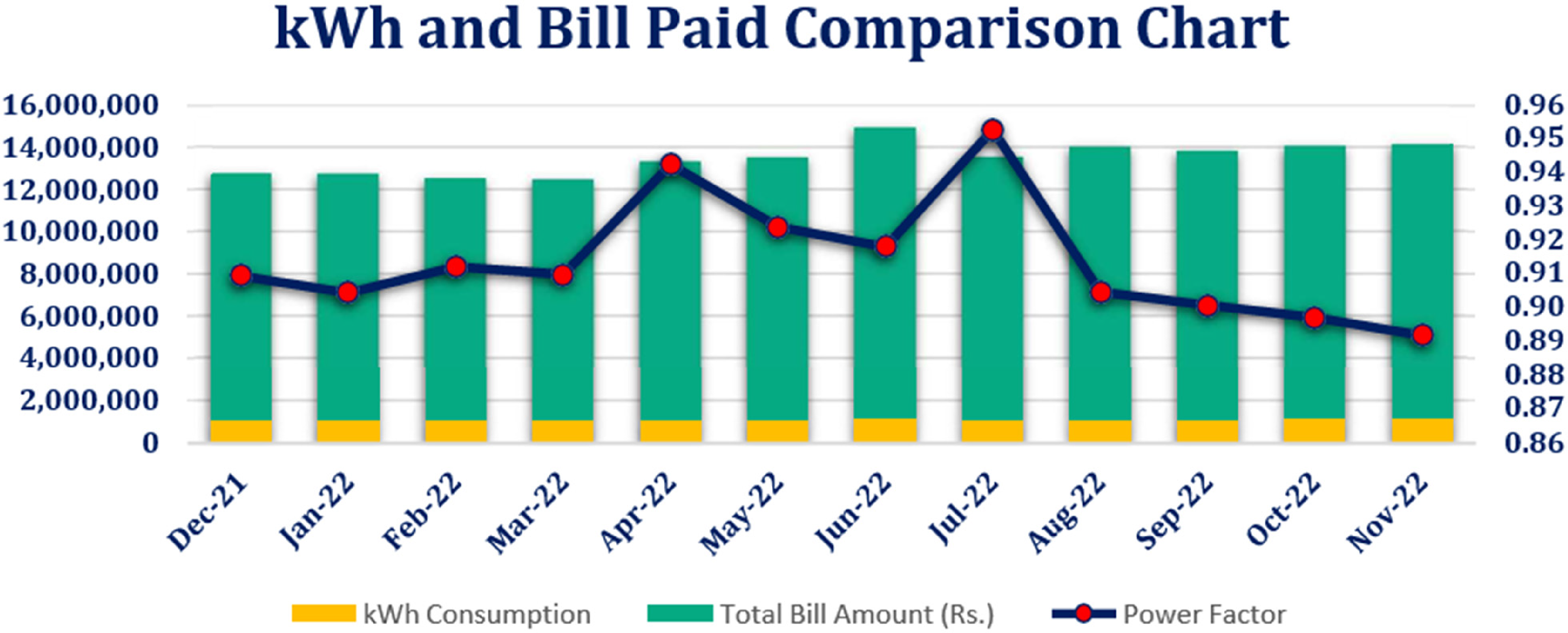
Graph of electrical energy consumption and bill paid pattern (2020–21) in mine.
The graph in Figure 8 illustrates the CD and billing demand for the mine from December 2021 to November 2022.
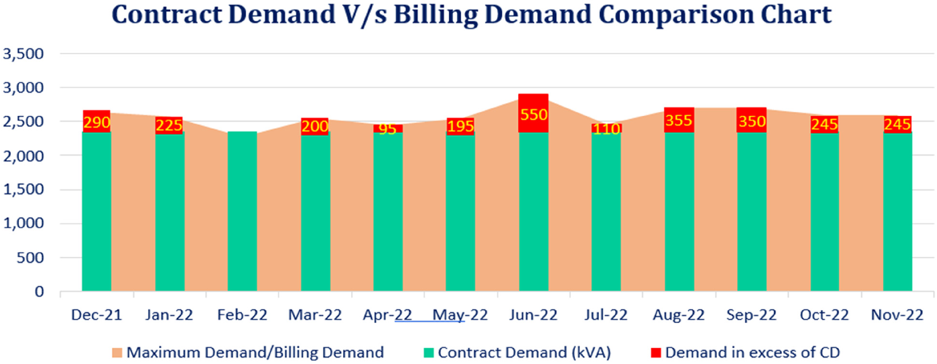
Graph of contract demand v/s billing demand compression chart (2021–22).
Figure 8 clearly illustrates that the maximum demand (MD)/billing demand was more than the CD in all months except February 22, when the MD was low, that is, 2275 kVA, while the CD was 2350 kVA. In the month of June-22, the recorded MD is up to 130% of the CD; therefore, Fixed charges for Excess Demand above 120% of CD must be levied at 1.3 times the regular fixed costs; this is an extra fee for Excess Demand (As per tariff order) (Ganapathi and Ananda, 2011; Fleiter et al., 2012a, 2012b, Singh et al., 2012).
As depicted in Figure 9, it is evident that a 1% penalty will be imposed on my account due to the power factor dropping below 0.90, specifically measuring 0.892, in the month of November-22. Refund is 1% on EC in the month of July-22 owing to PF arriving 0.953; therefore, it is apparent that obtaining Power Factor advantages when pf climbs beyond 95%. Maintaining power factor unity might provide additional motivation (Annunziata et al., 2014; Moya et al., 2016; Sultana and Harsha, 2015). Figure 10 displays the changes in TOD concerning the surcharge/rebate and load factor.
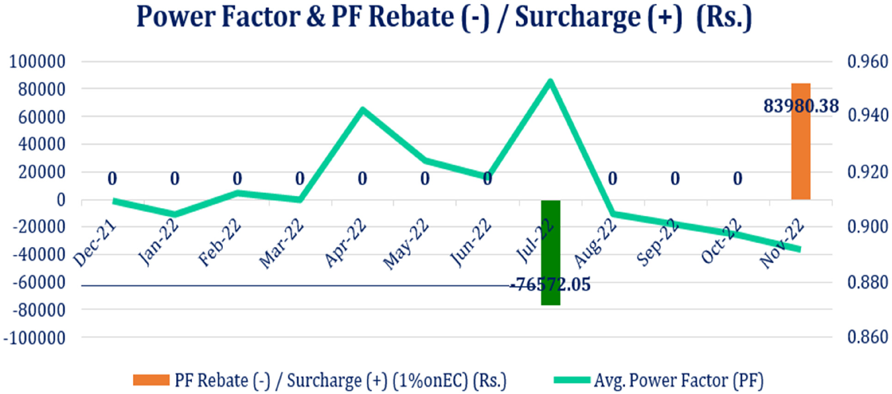
Graph of power factor & power factor rebate chart.
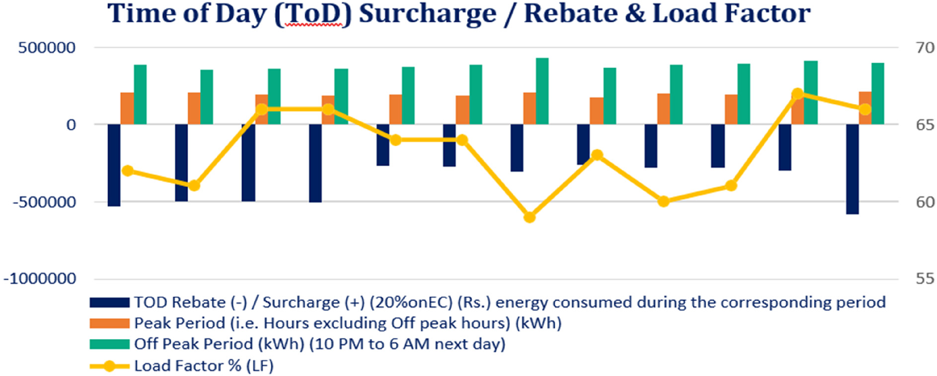
Graph of TOD surcharge/rebate & load factor.
Specific energy consumption (kWh/T)
The average overall SEC of Coal from Dec-21 to Nov-22 is 15.55 kWh/T. The graph in Figure 11 clearly indicates that the SEC was at its highest in August-22 and at its lowest in October-22 (Salunkhe et al., 2022; Sinuraya and Utsman, 2022; Zanardo et al., 2018).
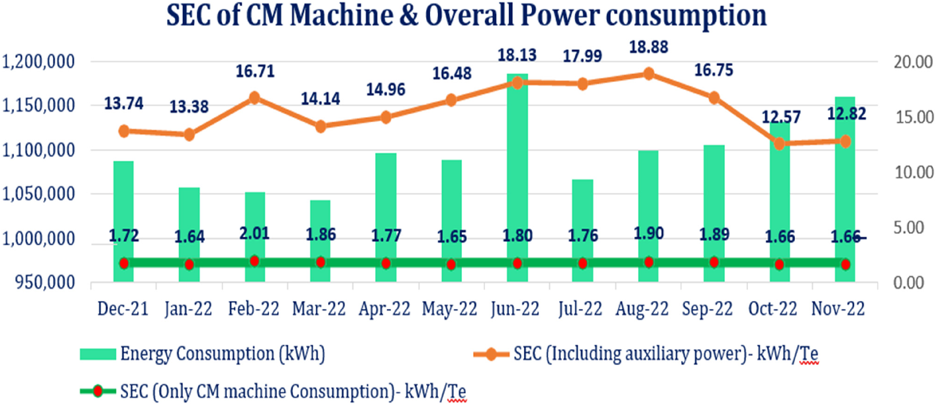
Graph of specific energy consumption of cm machine & overall power consumption profile.
Analysis of energy scenario of main substation
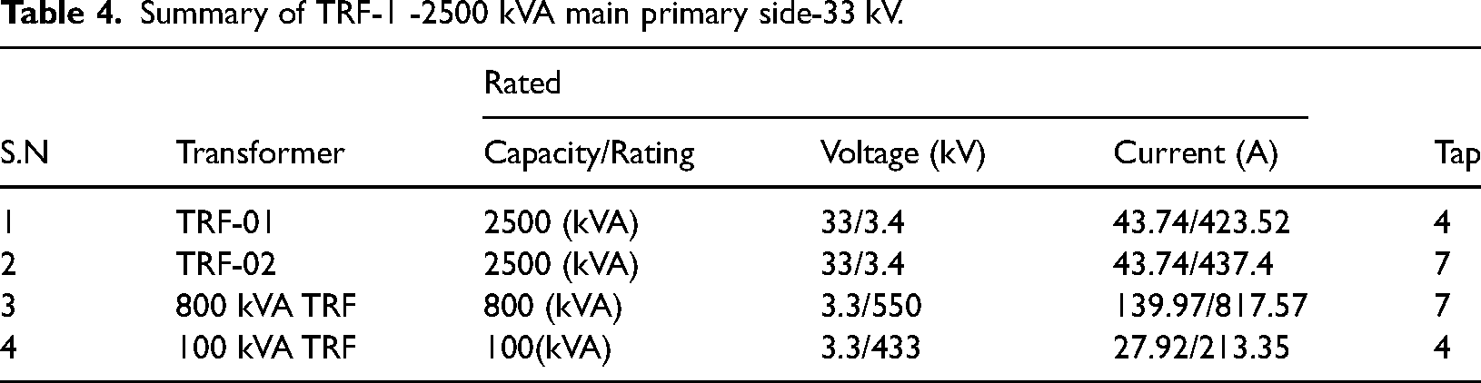
The main substation at the Mines has four transformers, and their specific details are provided in Table 4.
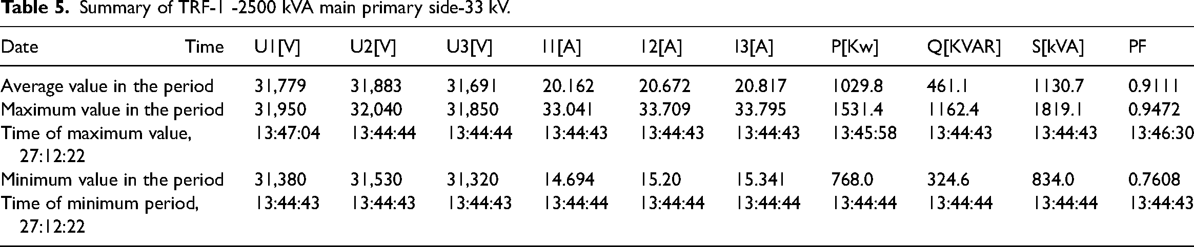
Summary of TRF-1 -2500 kVA main primary side-33 kV.
Iron losses and copper losses are the two forms of losses (Sejati and Melinda, 2023; Wardhana and SwiDamarwan, 2023). Although iron loss is constant regardless of load, copper loss I2R varies with load (Al Momani et al., 2023; Kluczek and Olszewski, 2017). Transformer should be loaded optimally to limit load loss to a minimal. Transformer performance is determined by current and power factor (Li et al., 2022; Wang et al., 2022b; Yin et al., 2023a).
Table 5 illustrates the usual load on a 2500 kVA transformer. On the primary side, the load fluctuates between a maximum of 1531.4 kW and a minimum of 768 kW. The operating power factor varies between 0.7608 (leading) to 0.9472 (lagging).
Summary of TRF-1 -2500 kVA main primary side-33 kV.
A power analyzer measures the flow of power (w) in an electrical system. While power is commonly expressed in terms of energy per second (J/s), this refers to the rate of electrical transmission between a power source and a drain (Sun et al., 2023; Xiao et al., 2023; Yin et al., 2023b). Observing power flow is a crucial yet straightforward task that can be done using a traditional power analyzer. More advanced systems, as shown in Figures 12–15, collect electrical signals and conduct integrated calculations for a more thorough analysis (Li et al., 2023b; Yu et al., 2022).
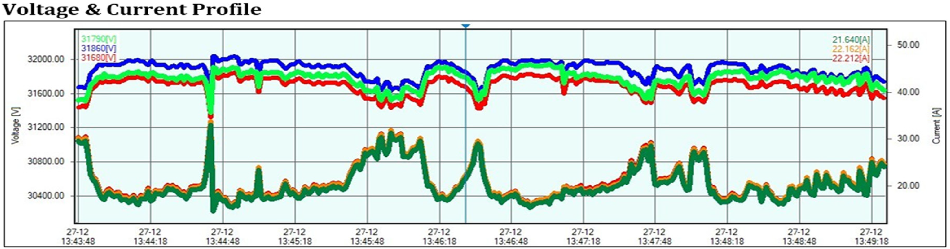
Graph of voltage & current profile of TRF-1-2500 kVA main primary side-33 kv main.
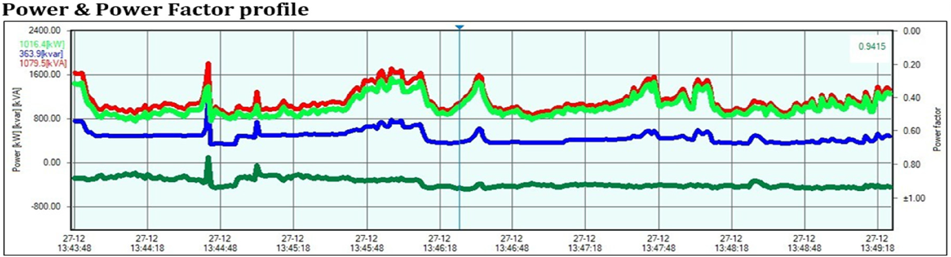
Graph of power & power factor profile of TRF-1-2500kVA main primary side-33 kv main.
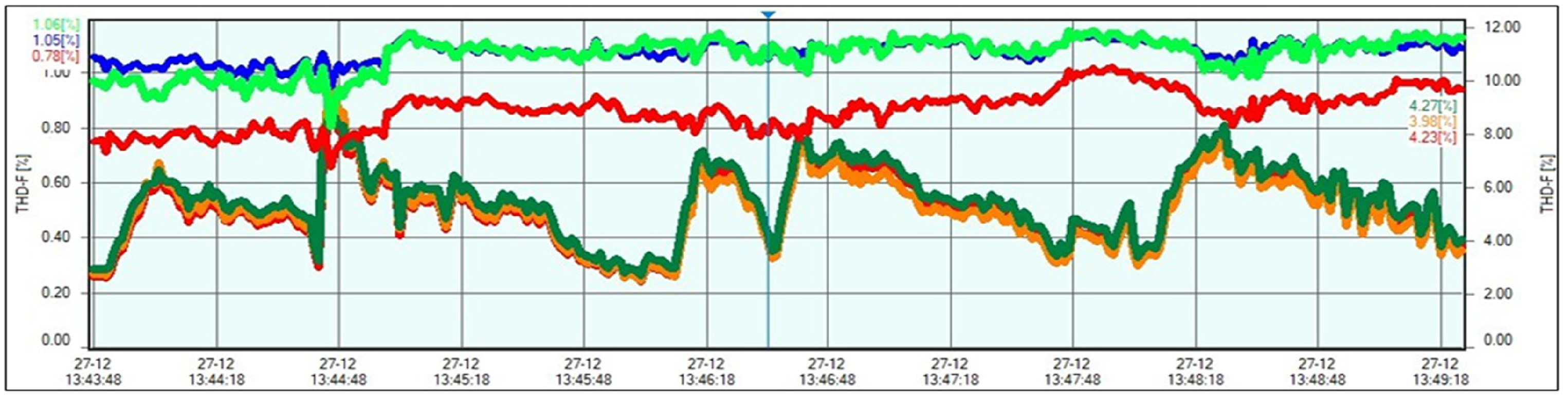
Graph of voltage & current harmonics profile of TRF-1-2500kVA main primary side-33 kv main.
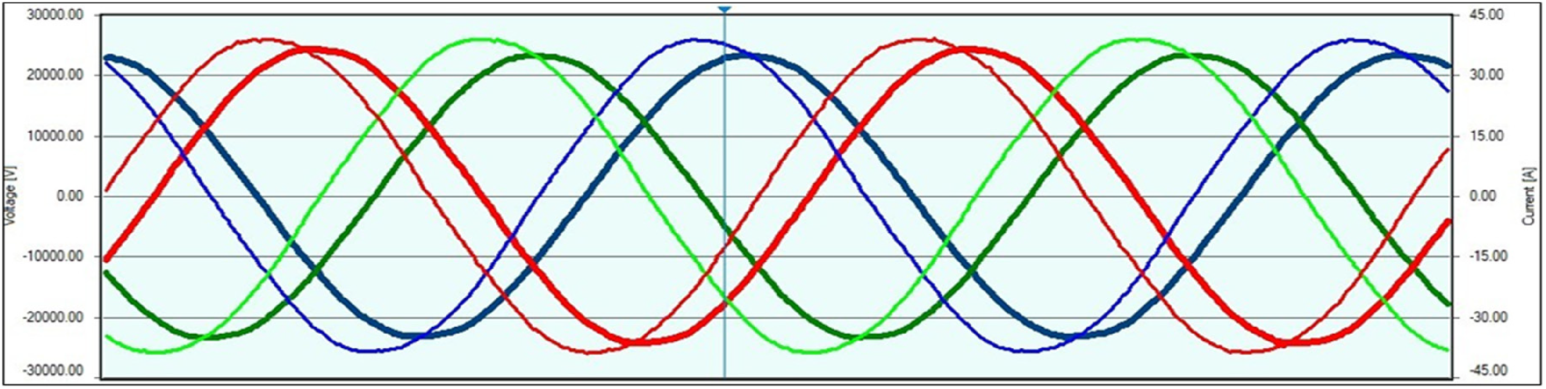
Graph of AC waveform profile of TRF-1-2500 kVA main primary side-33kV.
The power quality analysis tests for the 33kv main incomer-1 covered voltage, current, power, power factor, voltage and current harmonics and AC waveform for the four transformers outlined in Table 5, specifically on the primary side (Tie et al., 2023; Wang et al., 2022a). Following the generation of graphs for each test, we calculated the relative performance. Figure 16 presents a comparison graph showcasing the performance variations among different transformers.
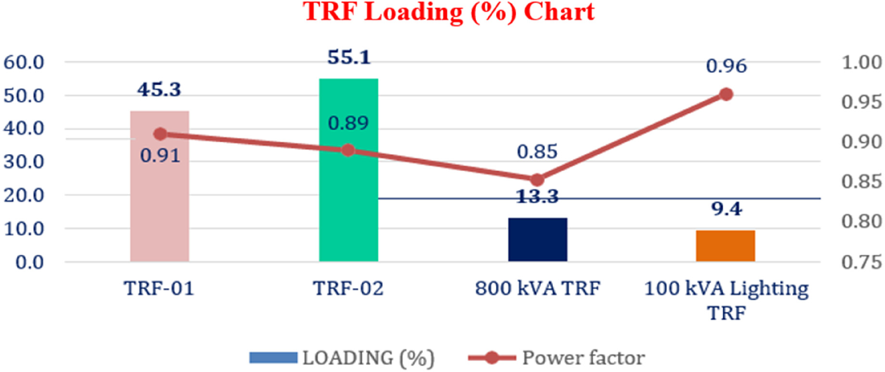
Graph of transformer loading (%) of power TRF.
Unbalance is defined as any departure in magnitude or phase shift from a perfect sinusoidal voltage and current waveform. Imperfections in the load produce current imbalance, which travels to the transformer and causes three-phase voltage unbalance (Jiang et al., 2022; Wang et al., 2023a; Wu et al., 2022). Even modest voltage imbalances at the transformer level dramatically disrupt the current waveform on all loads connected to it (Babu et al., 2023; Ma et al., 2023). A 1% imbalance is okay because it has no effect on the wire. Nevertheless, it grows linearly over 1%, and at 4%, the de-rating is 20%. This implies that 20% of the current flowing through the cable won't contribute to productive work, resulting in a 25% increase in copper losses within the cable when there's a 4% imbalance, as shown in Figure 17 (Chu et al., 2023; Khan and Alzahrani, 2022; Varun Kumar et al., 2022).
Graph of AC sinusoidal waveform profile of TRF-1-2500kVA main primary side-33kV.
The analysis of power quality and load for transformers involves measuring the actual loading conditions on the secondary side, as presented in Table 6.
Performance evaluation of 2500 kVATransformer-01 (primary Side).
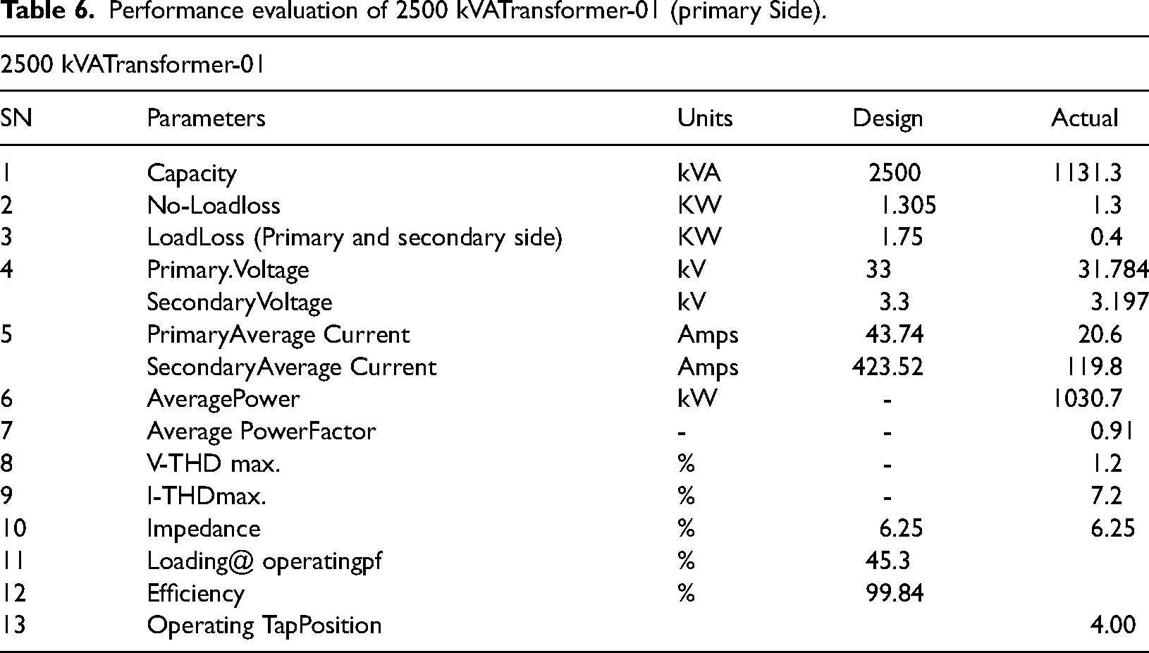
Loads on the 2500 kVA Transformer-01 (Primary side) is 45.3%, which is satisfactory. Distribution transformers typically have a maximum efficiency range of 40% to 60% transformer loading (Liu et al., 2023; Waqas et al., 2023; Xin et al., 2023). The preceding data shows that the HT voltage is 31.8 kV, which is fine. The tap operation is still in manual mode, and the transformer is set to the fourth position (Tripathi et al., 2022b, 2021c). As seen in Table 5, the power factor of the 2500kVA Transformer-01 (Primary side) is 0.91, which is somewhat lower (Tripathi et al., 2021b). Power Factor is affected by the kind of load. The use of a capacitor to keep the power factor constant (Tripathi et al., 2022a).
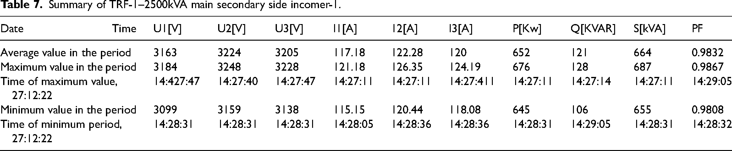
Based on the information in Table 7, for a standard load of 2500kVA, the highest load on the secondary side of the main transformer-01 Secondary side incomer-01 was 655 kW. The operational power factor varied from 0.9808 (leading) to 0.9867 (lagging) (Ansari et al., 2022; Dinkar et al., 2021).
Summary of TRF-1–2500kVA main secondary side incomer-1.
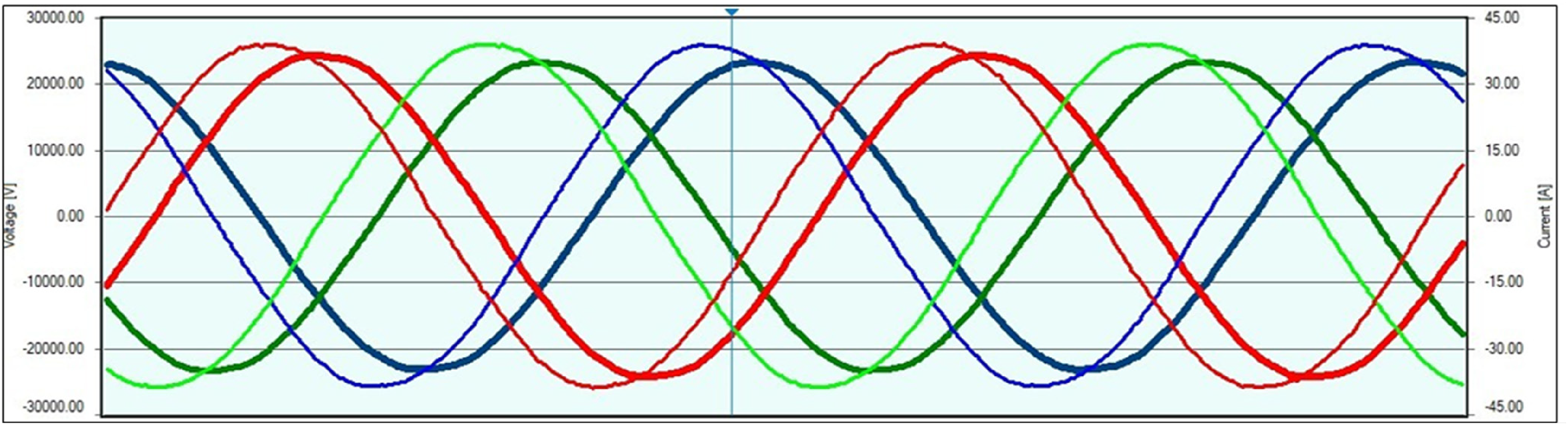
The voltage and current, power and power factor, voltage and current harmonics as well as AC waveform tests mentioned above were carried out on the four transformers specified in Figures 18–21, respectively, on the secondary side (Chattopadhyaya et al., 2021; Li et al., 2023c; Tripathi et al., 2022c). The graph in Figure 22 depicts the maximum versus operating efficiency of these transformers.
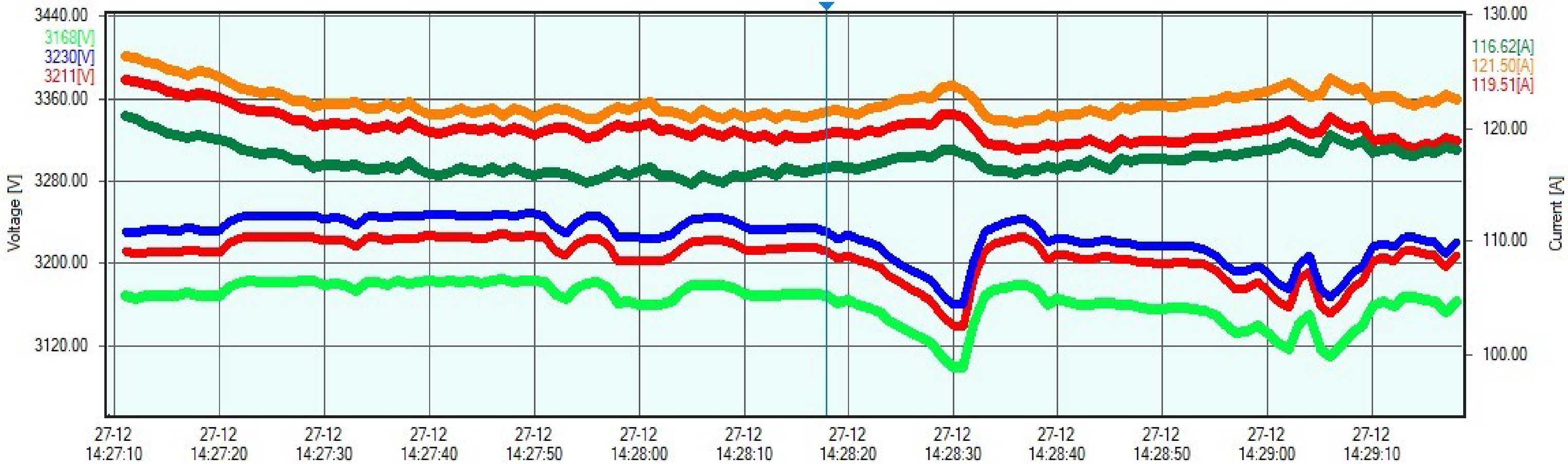
Graph of voltage & current profile of TRF-1-2500kVA main secondary side incomer-1.
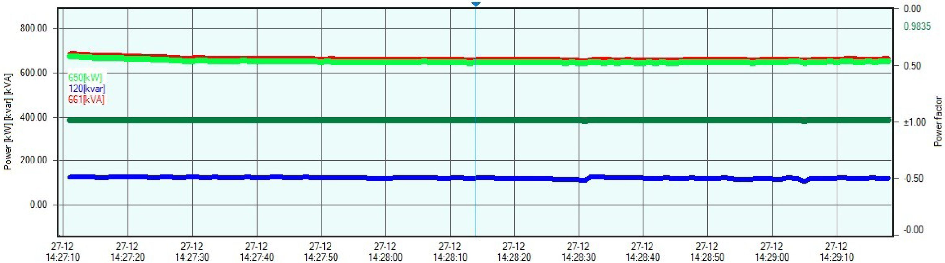
Graph of Power & Power Factor profile of TRF-1-2500kVA main secondary side incomer-1.
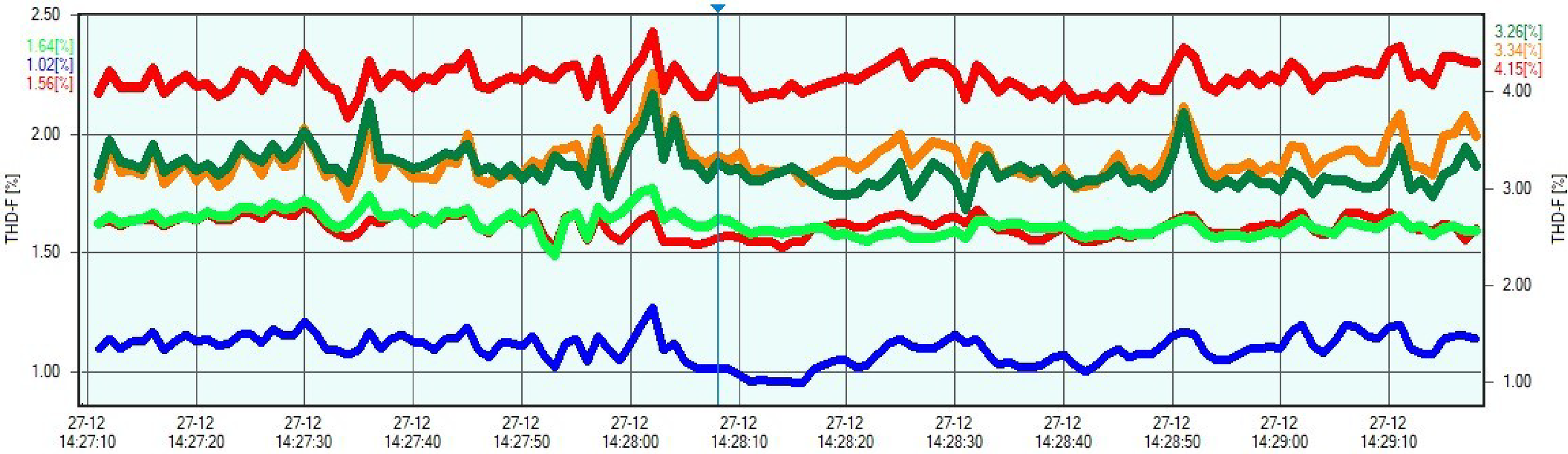
Graph of Voltage & Current Harmonics profile of TRF-1-2500kVA main secondary side incomer-1.
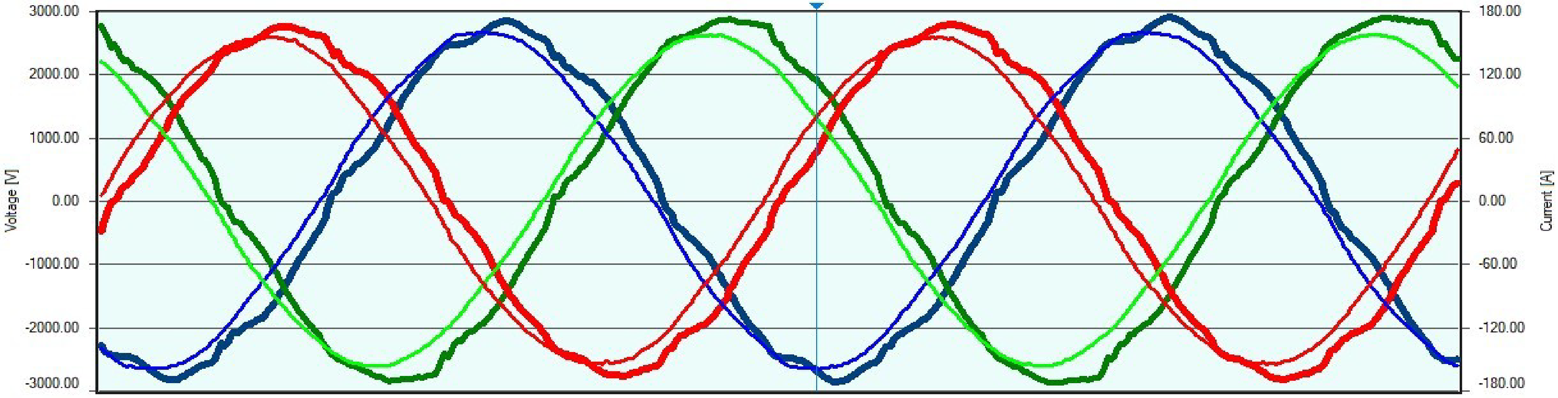
Graph of AC waveform profile of TRF-1-2500kVA main secondary side incomer-1.
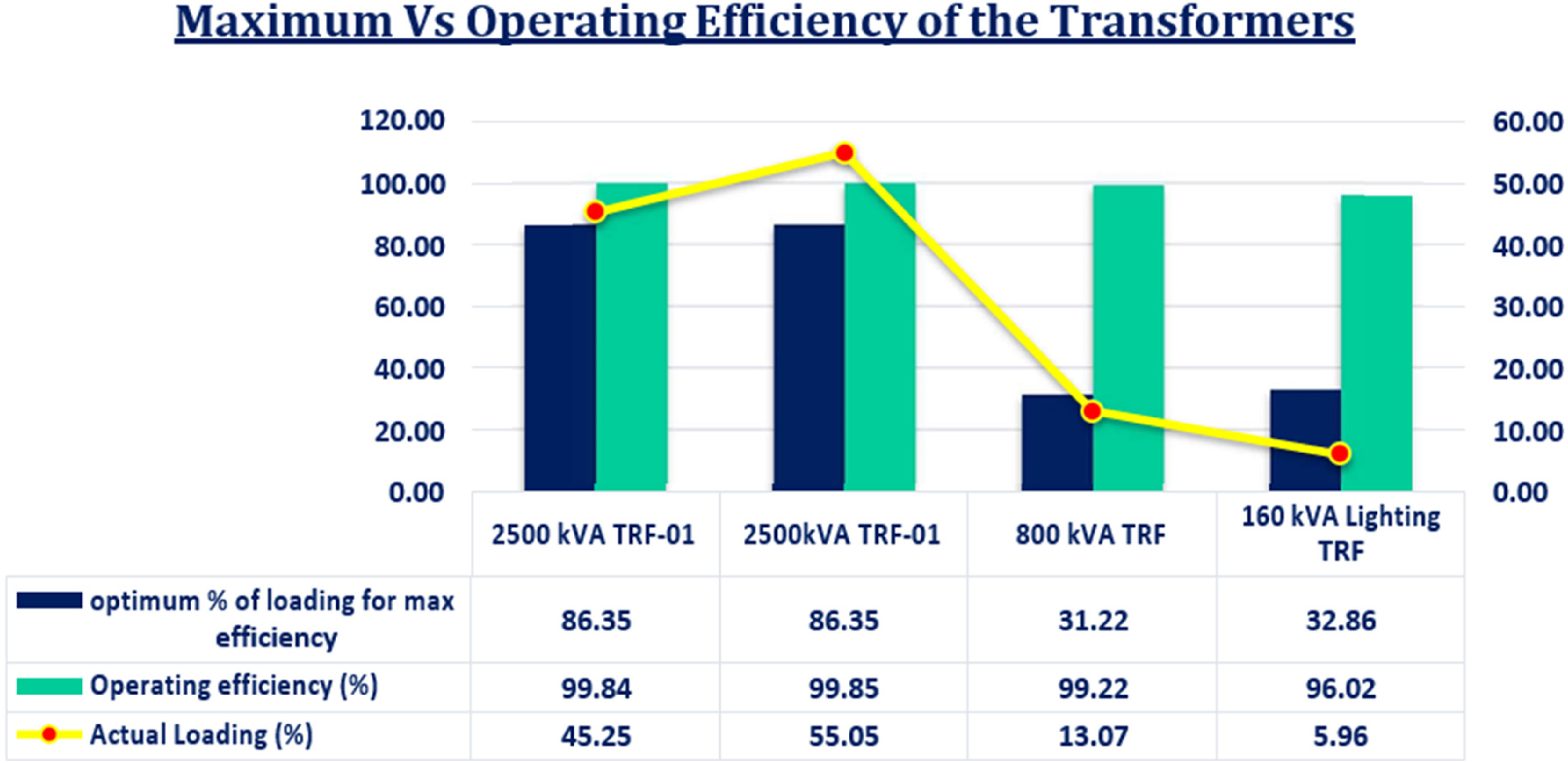
Graphof maximum vs operating efficiency of the transformers.
Harmonics analysis
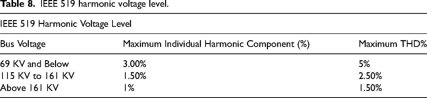
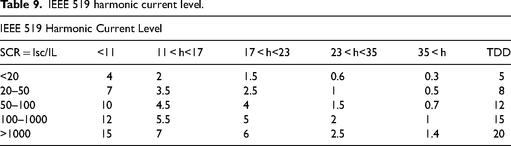
Harmonic studies are performed to evaluate harmonic distortion levels and filtering requirements inside a facility, as well as to determine if harmonic voltages and currents are within allowable limits (Muhammad et al., 2022; Suresh Kumar et al., 2023). The usage of harmonic filters will significantly alter the frequency response of the power supply. The existence of harmonics in the system is verified based on the IEEE 519–2014 standard. It is essential to maintain both voltage (refer to Table 8) and current (refer to Table 9) at the prescribed PCC levels.
IEEE 519 harmonic voltage level.
IEEE 519 harmonic current level.
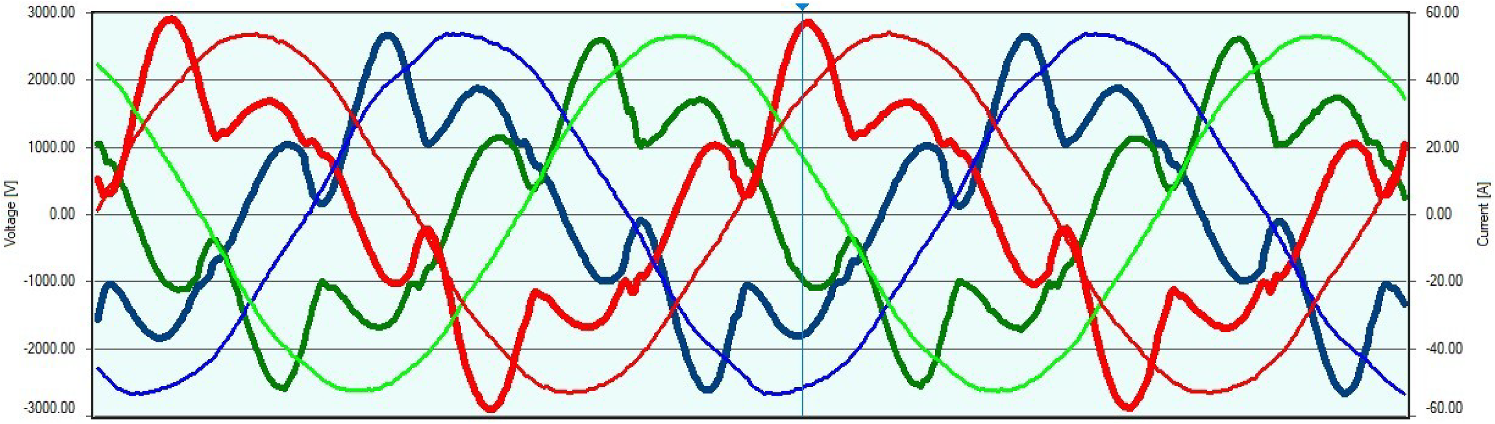
Harmonics refer to distortions in the voltage and current waveforms, as revealed in Figure 23. It is a reference wave's integral multiple (Rafiq et al., 2023). The harmonic wave increases the transformer's core and copper loss, lowering its efficiency. It also raises the dielectric stress on the transformer's insulation (Siddiqui et al., 2022c). The non-sinusoidal nature of magnetizing current provides sinusoidal flux in a three-phase transformer, resulting in the unwanted occurrence. The phase magnetizing currents in a transformer should include the third and higher harmonics required to generate a sinusoidal flux (Bhushan et al., 2022; Siddiqui et al., 2022a).
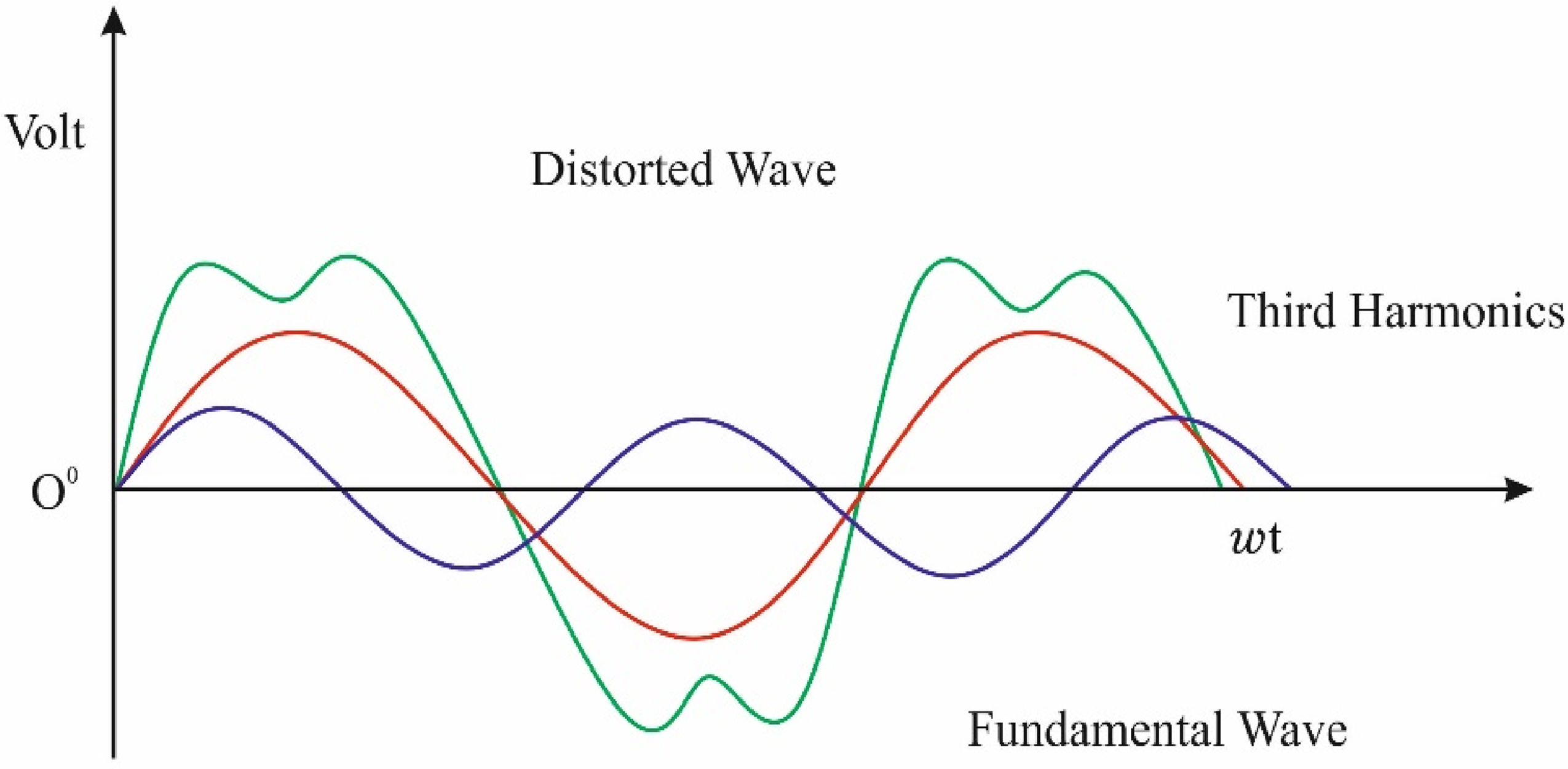
Graph of harmonics.
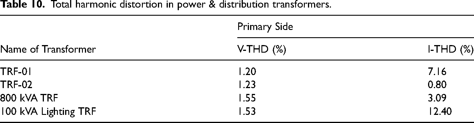
Voltage Harmonic Distortion falls within the range of 1.20% to 1.55%, as indicated by the harmonic at the PCC in Table 10, which is within acceptable limits. Current harmonics on the main side of transformers vary from 0.80% to 12.4%, remaining within acceptable limits (Sun et al., 2023; Wang et al., 2023b; Xiao et al., 2023). However, on the 100kVA lighting transformer, I-THD is recorded at 12.40, which is on the higher side, as depicted in Figure 24.
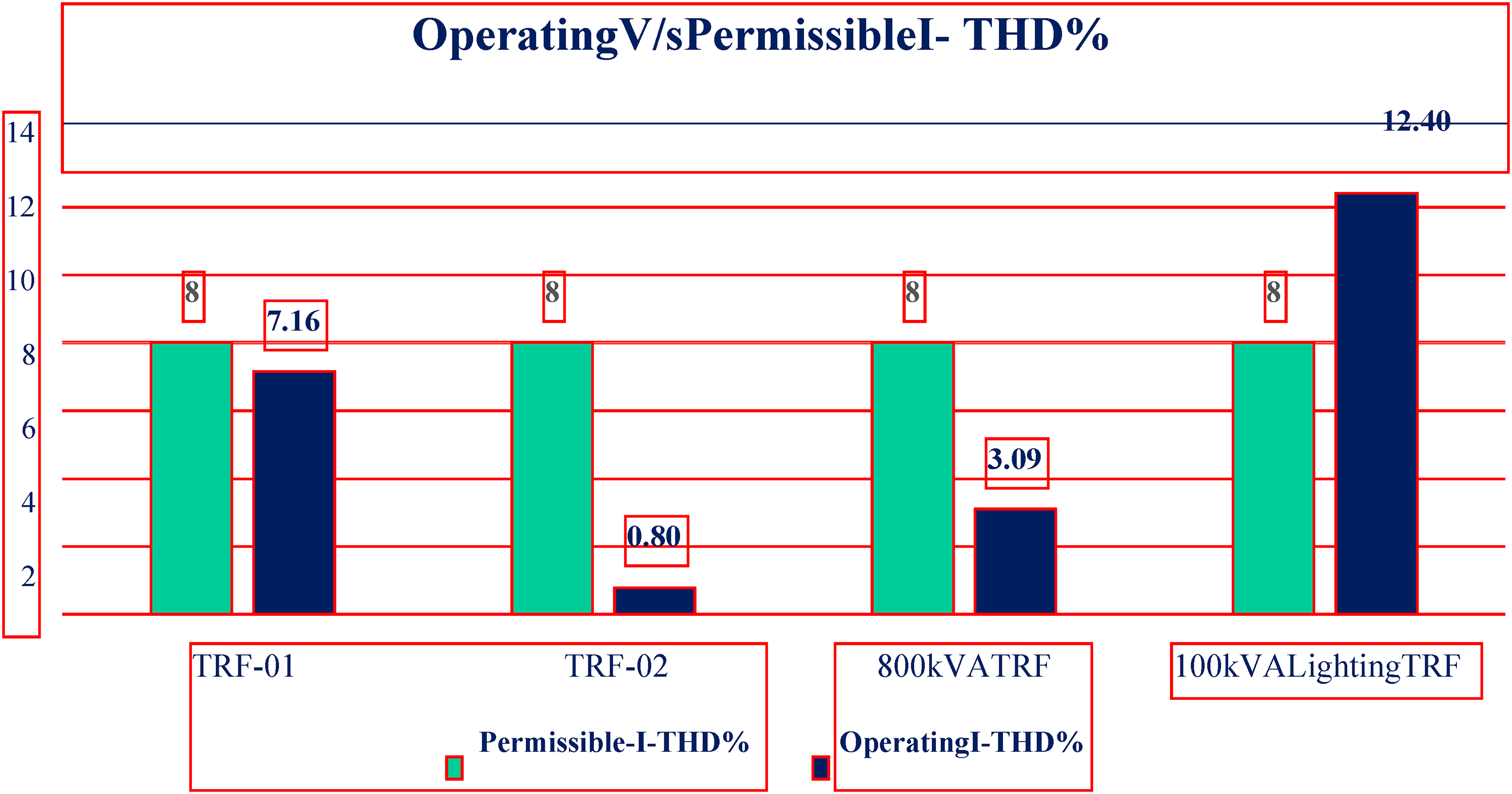
Graph of permissible limit v/s operating I-THD% profile of Transformers.
Total harmonic distortion in power & distribution transformers.
2.5 MVATRF-1(33 kV)
The harmonic profiles for the 2.5 MVA Transformer (TRF-1) at 33 kV are shown in Figures 25 and 27.
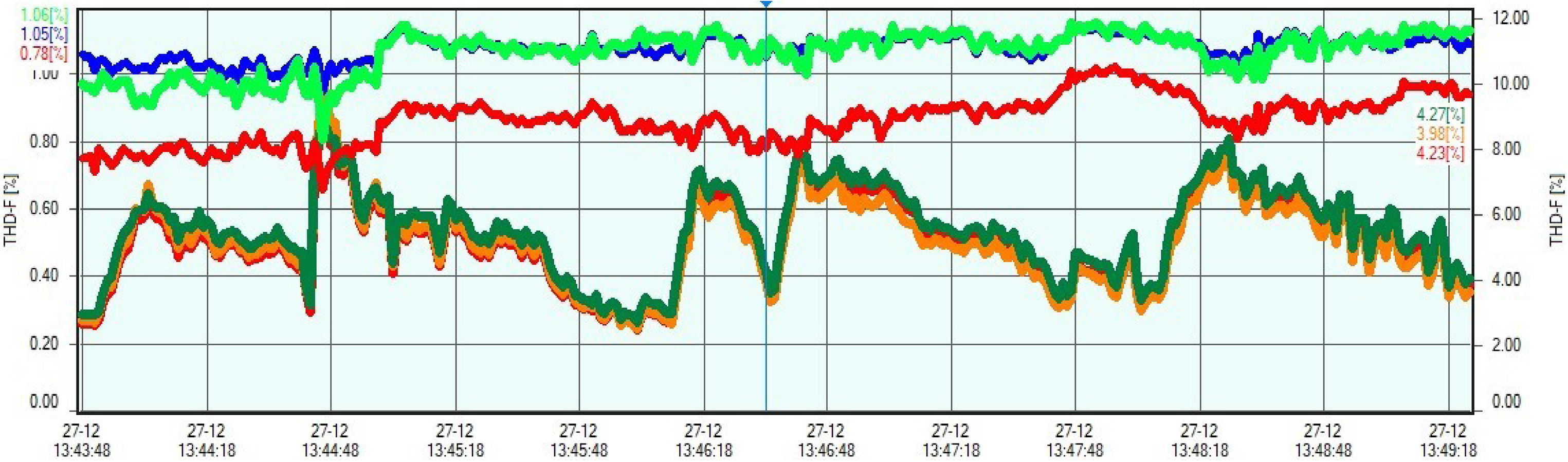
Graph of harmonics profile.
Graph of sinusoidal waveform.
Harmonic profiles for the 2.5 MVA transformer at 33 kV are displayed in Figure 27. These graphs offer insights into the distribution and characteristics of harmonics, aiding in understanding their impact on the transformer's electrical performance and providing valuable data for power quality analysis and optimization (Li et al., 2023a; Yan et al., 2024; Yu et al., 2022).
Graph of waveform, 2.5 MVA, primary side (33KV).
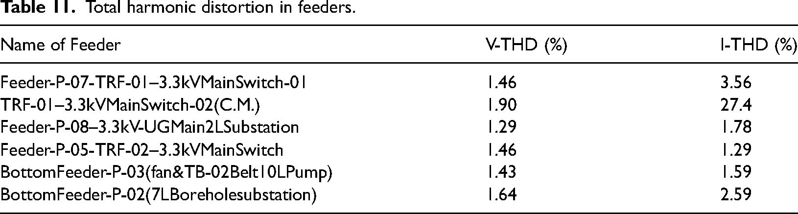
Referring to the information in PCC (Tables 10 and 11), the Voltage Harmonic Distortion falls within the acceptable range, ranging from 1.29% to 1.90%. Similarly, the Current Harmonic Distortion, as indicated in the PCC table, fluctuates between 1.29% and 3.56%, remaining within acceptable limits (Fan and Zhou, 2023; Hu et al., 2024b; Jiang et al., 2022). However, it's noteworthy that for TRF-01–3.3 kV Main Switch-02 (C.M.), the I-THD reaches 27.4, which is higher, as illustrated in Figures 28–30.
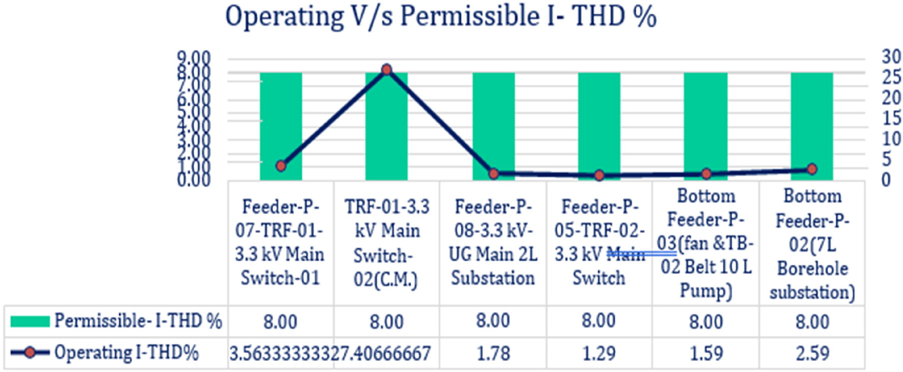
Graph of permissible limit V/s operating I-THD% profile of feeder.
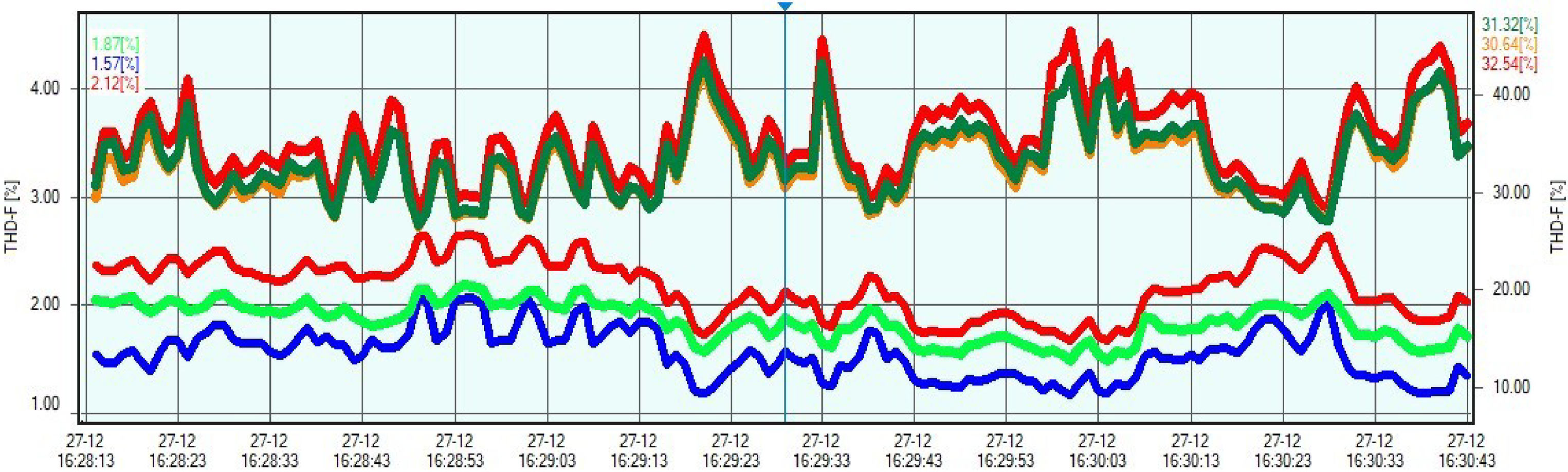
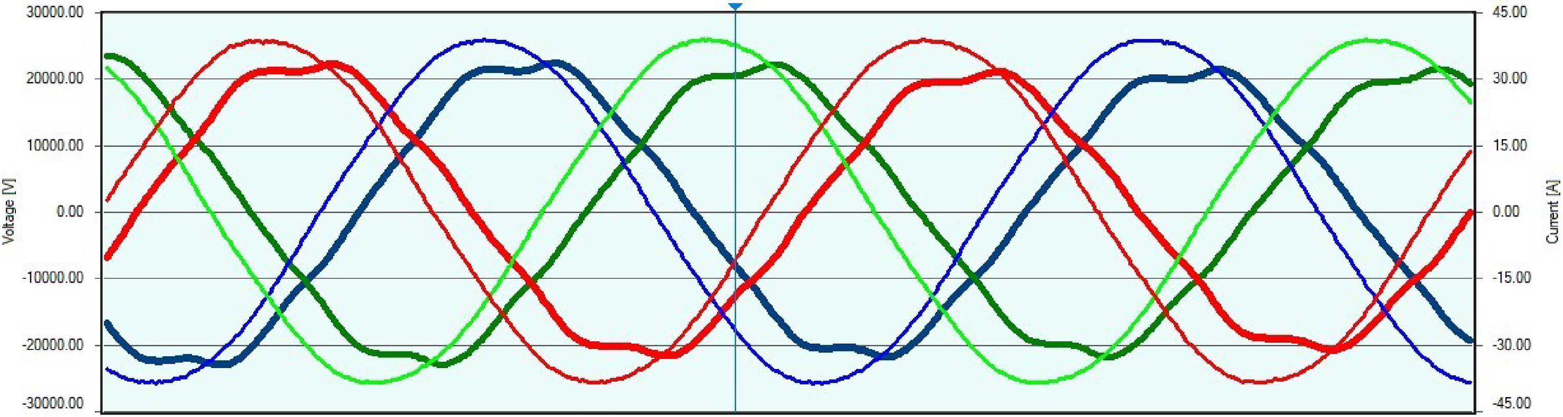
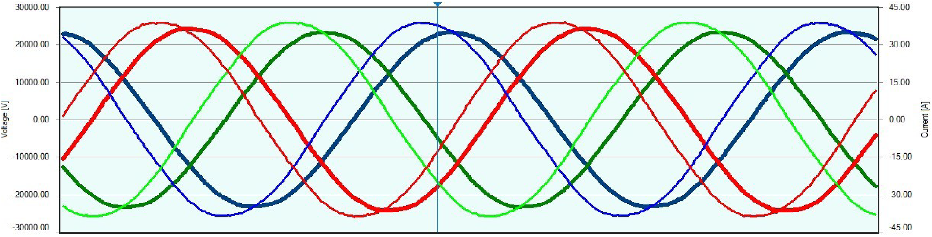
Graph of voltage & current harmonics profile of TRF-1-2500 kVA main secondary side-incomer-02 (C.M.Main).
Graph of AC waveform profile of TRF-1-2500 kVA main secondary side-incomer-02 (C.M.Main).
Total harmonic distortion in feeders.
Thermal imagining of Electrical panels
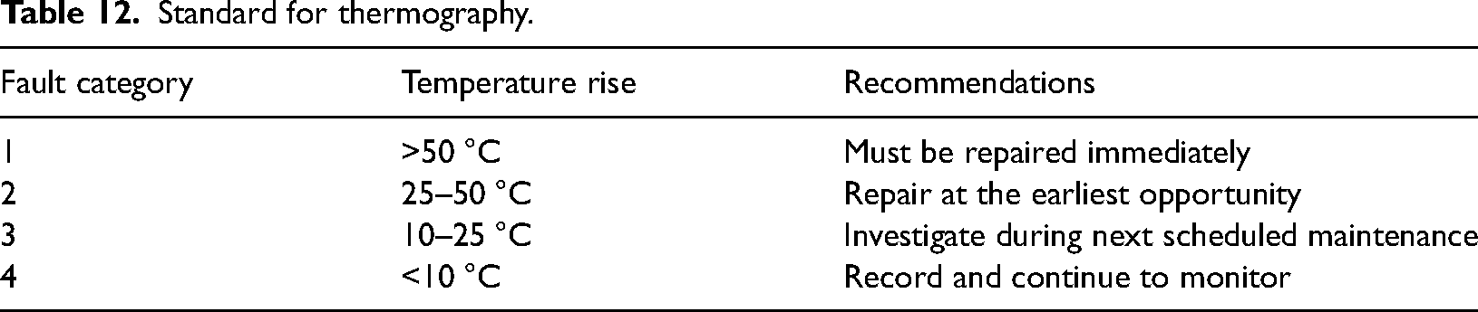
Thermography serves as a non-destructive testing method that proves invaluable in identifying issues such as poor connections, unbalanced loads and deteriorated insulation within energized electrical components (Su et al., 2023; Wang and Zhang, 2023; Xi et al., 2023). Detecting these potential problems is crucial as they can contribute to excessive power consumption, heightened maintenance expenses, or even result in catastrophic equipment failure, leading to unscheduled service interruptions, equipment damage and other operational issues (Kluczek and Olszewski, 2017). In accordance with the Bureau of Indian Standards, Table 12 provides a comprehensive guide for assessing the severity of electrical fault temperatures and offers corresponding recommendations:
Standard for thermography.
During the thermal imaging analysis presented in Figures 31–34, it was observed that none of the equipment generated heat beyond the recommended levels. Enhancing the thermal performance of electrical equipment can be achieved without altering the existing operational conditions. A state-of-the-art thermal imaging camera was deployed to meticulously measure the heat generation in various components, including incoming and outgoing feeders, transformers, switches, power cables and all connections (Du et al., 2024; Yin et al., 2023a). This advanced approach allows for a detailed and comprehensive analysis of the thermal behaviour, paving the way for targeted improvements without disruption to the current operational setup.
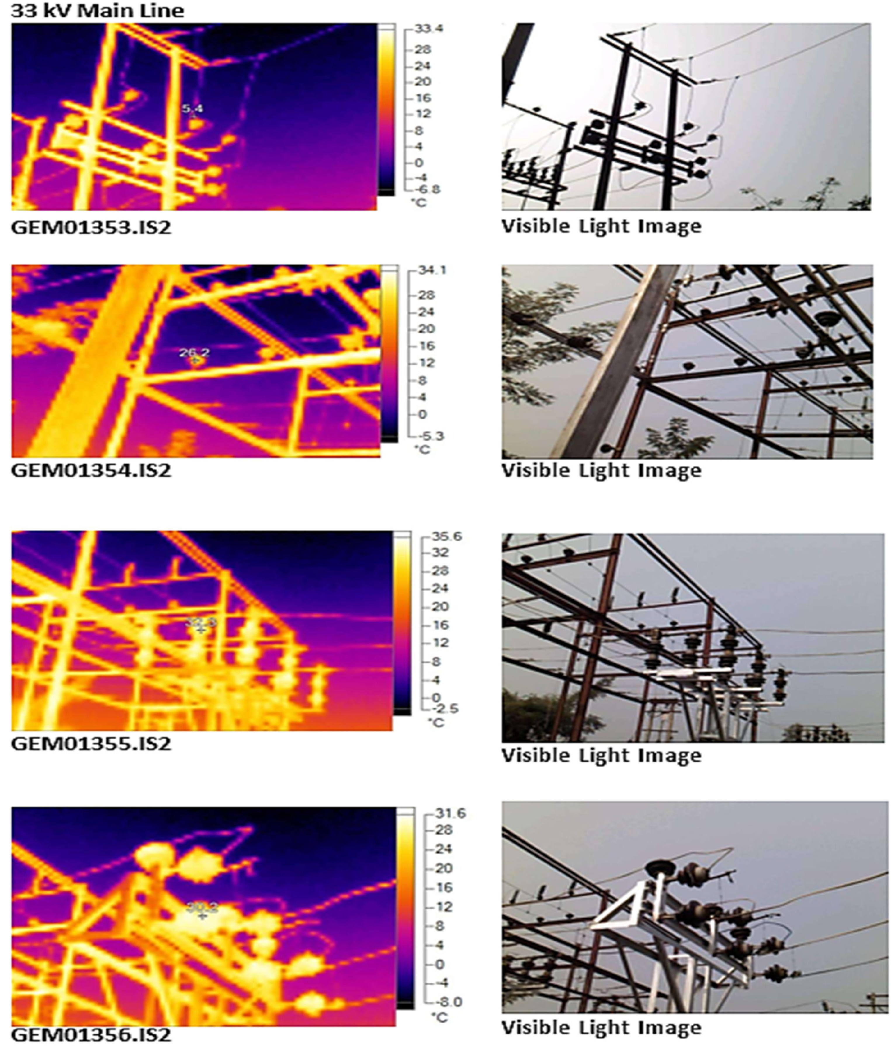
Thermal and normal image of 33kV main overhead lines.
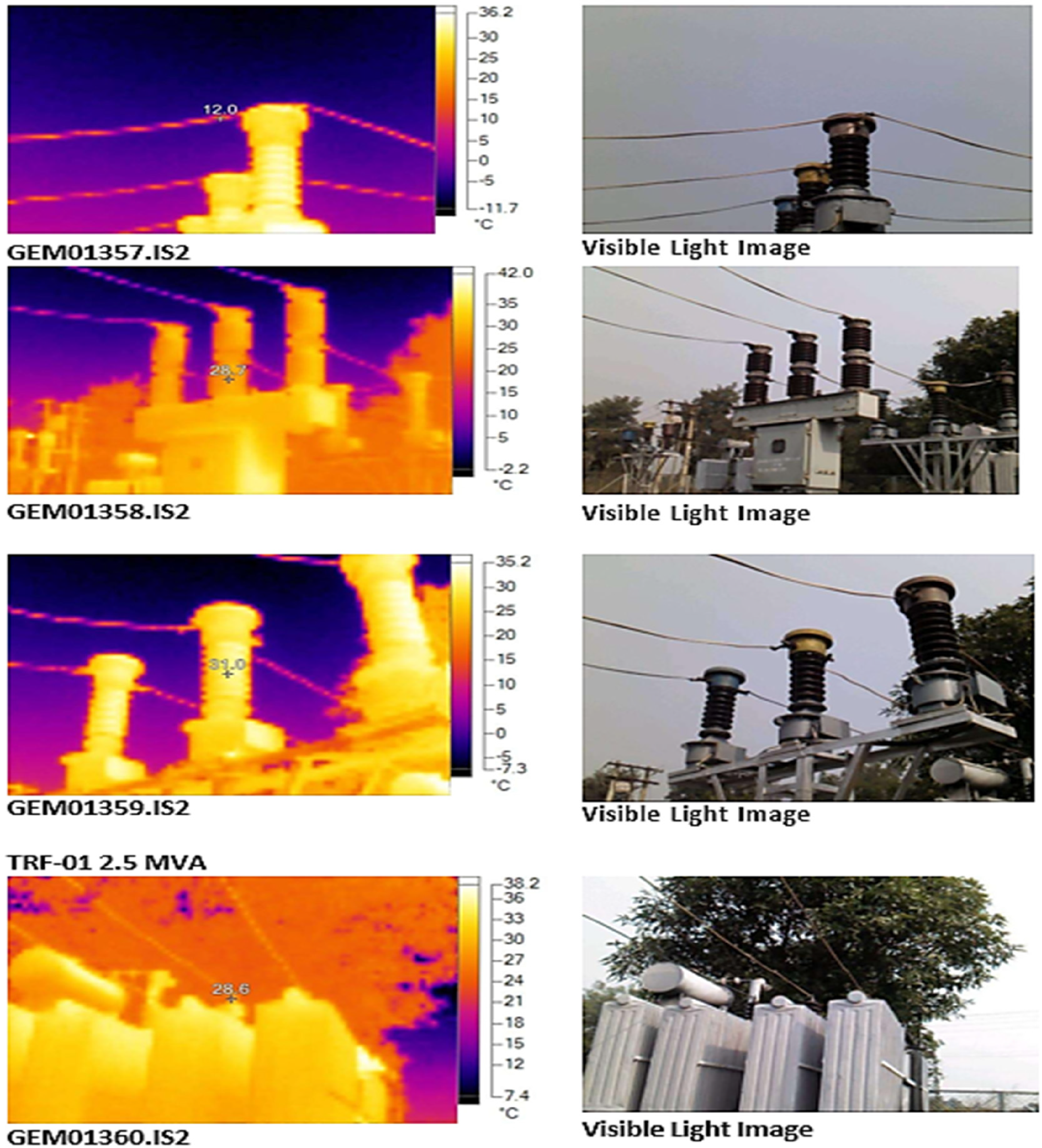
Thermal and normal image of 33kV main substation.
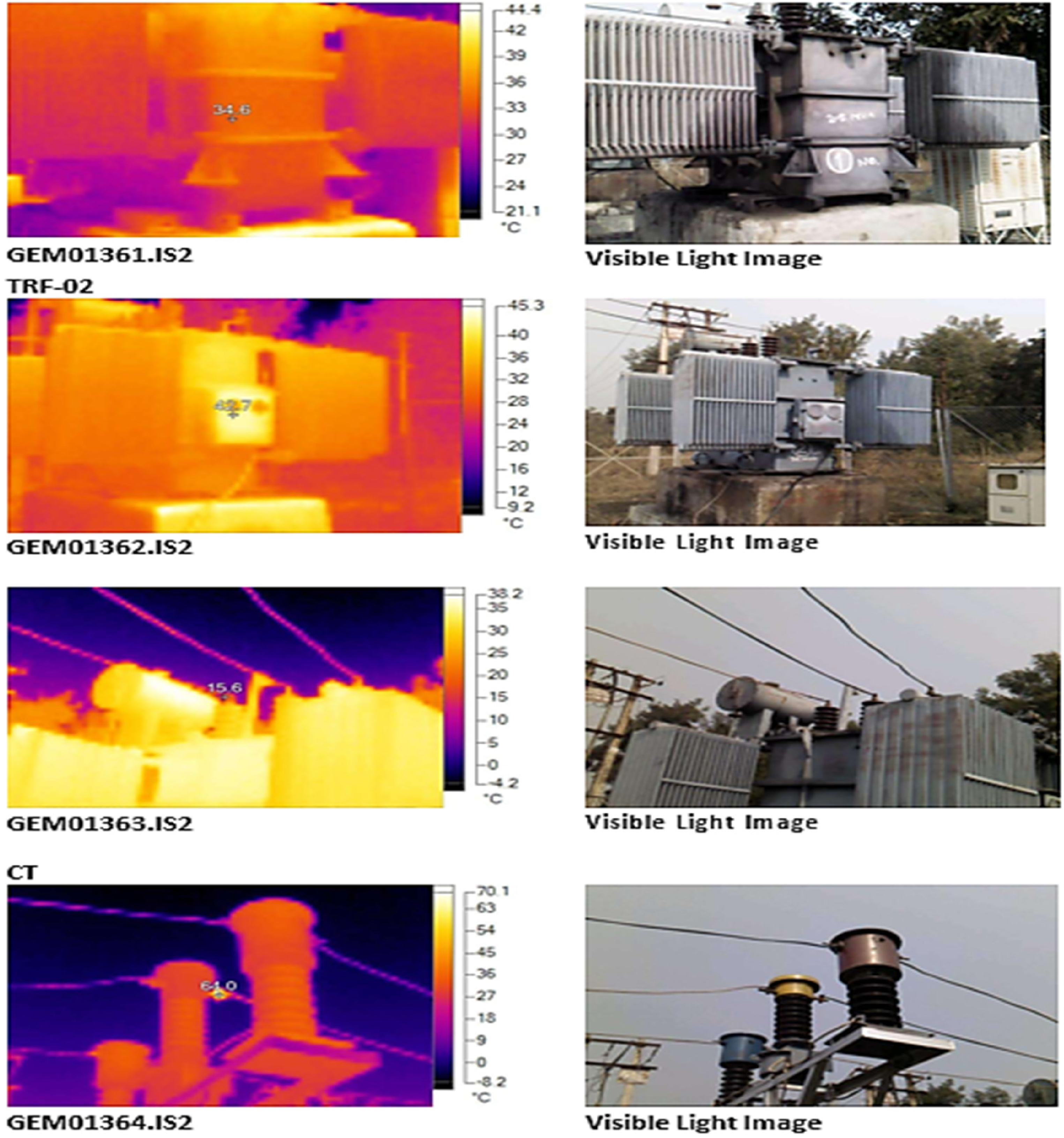
Thermal and normal image of 33kV main transformers.
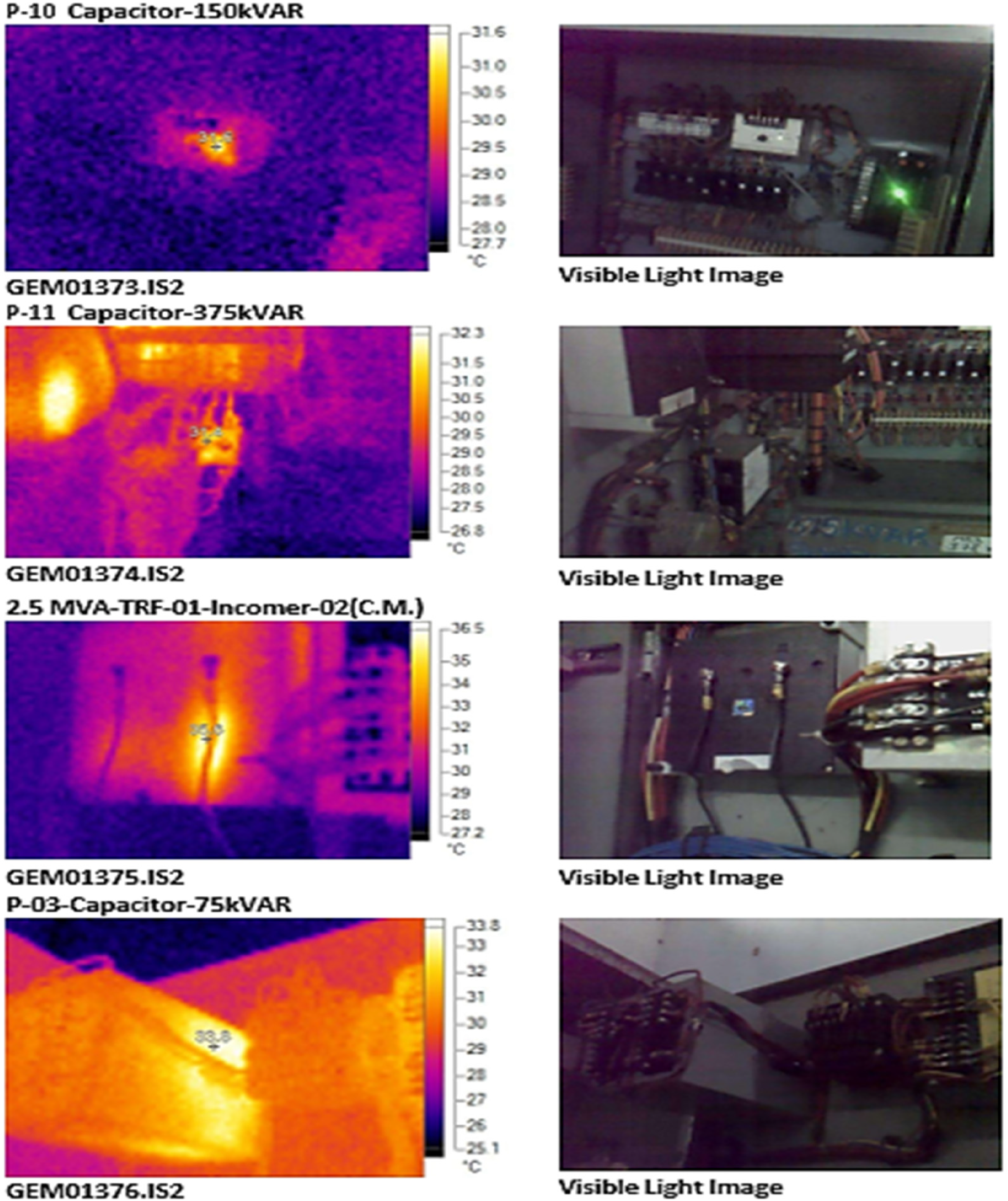
Thermal and normal image of 150 KVAR capacitor.
Result and discussions
The investigation into the realm of electrical power factor and its implications on electricity bills has yielded significant findings. In November 2022, a penalty of 1% was incurred due to the power factor falling below 0.90, specifically recording 0.892. Conversely, a Power Factor Rebate of 1% on the Energy Cost in July 2022 was granted because the power factor exceeded 0.953. Achieving a power factor above 95% not only avoids penalties but also brings substantial benefits, including rebates ranging from 1% to 7% on the Energy Cost. This indicates a scenario where the electrical system demonstrated high efficiency and effective power utilization, resulting in a reward in the form of a rebate (Abou-Rjeily and Mourad, 2020; Bouri, 2023; Liang et al., 2024).
The dynamic nature of electrical grids, with variations in demand throughout the day, underscores the significance of TOD pricing structures. These aim to incentivize consumers to shift energy consumption to periods of lower demand. The rebate offered during off-peak load periods (10 p.m. to 6 a.m.) serves as an economic strategy, encouraging consumers to use electricity when overall demand on the grid is lower (Bhushan et al., 2022; Bouri and Shahzad, 2022; Maalouf et al., 2020). This aligns with the principle of optimizing resource utilization by promoting energy consumption during surplus capacity periods (Bhushan et al., 2022; Gharibeh et al., 2022; Harb and Bassil, 2023).
Figures 8–10 provide valuable insights into the dynamics of demand, informing a strategic approach to demand management. When recorded MD surpasses 130% of the agreed-upon CD, an additional layer of cost is introduced. Electrical systems face challenges during peak demand periods, leading to charges at double the standard fixed rate for recorded demand exceeding 130% of the CD (Dhiaf et al., 2024; El-Khalil and Nader, 2020; Nader and EL-khalil, 2021). This reflects the economic reality that providing electricity beyond certain thresholds incurs additional costs (Bhushan et al., 2022; Bouri et al., 2023; Su et al., 2023; Yu et al., 2022).
The operational status of transformers further adds depth to the discussion. Transformer-1 operating at 45.3% suggests a conservative or underutilized state, while Transformer-2 at 55.1% is performing admirably, indicating a healthier and more efficient operational state (Yin et al., 2017; Yu et al., 2024; Zheng et al., 2023).
Reference to voltage and current imbalances, depicted in Figure 17, indicates that these imbalances are well within acceptable limits. This emphasizes the importance of maintaining balance in electrical systems to prevent inefficiencies, increased losses and potential issues with equipment performance (Bhushan et al., 2022; Yin et al., 2023a; Zhao et al., 2024).
In the context of power factor enhancement, the suggestion to consider installing capacitors on the load side aligns with the scientific principle of power factor correction (Hu et al., 2024a; Jin et al., 2024; Liu et al., 2024). Additionally, examining secondary voltage in the 33 kV main substation within an acceptable range (3.37–3.42 kV) signifies a well-regulated electrical environment. Voltage regulation is crucial for maintaining a stable and reliable power supply (Bhushan et al., 2022; Liang et al., 2024; Tripathi et al., 2021d).
The thermal analysis, showcased in Figures 31–34, highlights the equipment's exceptional performance under varying temperatures. None of the devices crossed the recommended thresholds, affirming their ability to maintain cool composure even under challenging thermal conditions (Bhushan et al., 2022; Orbak et al., 2023; Tripathi et al., 2021a).
Hence, the intent of this research is to improve our comprehension of the performance of electrical equipment in heavy mines machinery by employing a distinctive set of energy audit instruments in comparison with prior studies (Tripathi et al., 2023a, 2023b, 2023c). This research illuminates the dynamics of mine apparatus and its electrical components, in contrast to extant studies that concentrate on energy efficiency in a variety of domains (Tripathi et al., 2023d; Ulug ’bek O ’g ’li et al., 2023; Yao et al., 2023). The study explores the nuanced analysis of energy wastage using innovative methods such as Harmonics and Thermal imaging, with the objective of offering specific recommendations for improvement. The research aims to be a catalyst for transformative improvements in the energy efficiency of heavy subterranean machinery by addressing these unexplored voids, thereby contributing to a more sustainable and productive future for the mining industry in comparison with literary studies (Siddiqui et al., 2024; Tripathi et al., 2023e).
In addition, several strategies are recommended by harmonic analysis to reduce harmonic distortion in electrical systems. These include the substitution of conventional transformers with specialized harmonic-mitigating variants that incorporate distinctive winding configurations or magnetic shielding. Furthermore, harmonics can be effectively mitigated by selecting low-harmonic emission equipment or incorporating line reactors for inductive loads. The utilization of phase-shifting transformers facilitates load distribution balancing, while the installation of passive or active harmonic filters provides targeted harmonic reduction. Harmonic distortion is further reduced by guaranteeing stable voltage levels and equitable load distribution. Continuous monitoring is essential for the ongoing optimization of a system, as it enables the timely implementation of alterations and maintenance to preserve its integrity and performance.
Conclusions
The energy audit emerges as a powerful instrument for identifying and implementing a comprehensive energy management program. Through a meticulous audit, organizations can formulate a strategic plan to manage their energy systems effectively, ensuring minimal energy costs.
In essence, the tariff order's provisions represent a blend of scientific and economic principles, aiming to incentivize consumers to uphold high-power factors. This not only contributes to the overall efficiency and reliability of the electrical grid but also aligns with a fair and transparent cost structure.
The significance of TOD pricing lies in its principles of optimizing energy consumption based on temporal variations in demand. By encouraging consumers to synchronize electricity usage with periods of lower demand and promoting efficient power factor management, TOD pricing becomes a cornerstone for achieving cost savings and enhancing grid reliability.
Exploring electrical demand patterns, the relationship between recorded MD and CD, and the economic rationale behind excess demand charges emphasizes the importance of a fair and transparent cost structure aligned with actual demand scenarios.
Moreover, the mention of distribution transformers engineered for optimal efficiency within the 50–60% loading range underscores a fundamental engineering philosophy. Operating transformers within this loading range is strategically designed to maximize performance, minimize losses and ensure longevity, aligning with principles of transformer design and efficiency.
In this dynamic landscape, optimization strategies such as capacitive installations and load adjustments play a pivotal role in fine-tuning the system for peak performance. This scientific approach involves continually optimizing and adjusting system parameters to achieve the utmost efficiency and reliability.
Finally, the discussion on thermal analysis highlights the equipment's resilience under varying temperatures. The use of visual data and adherence to recommended thresholds illustrates a scientific methodology employed to ensure the thermal stability and reliability of the equipment.
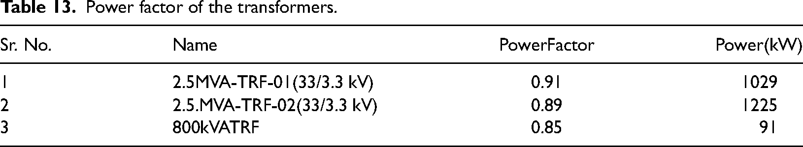
Installation of APFC (Automatic Power Factor Controller) in secondary side of transforms to achieve the power factor from 0.85 to 0.99 as illustrated in Table 13. Present status during the energy audit, loading pattern and power factor of all the Transformers, Feeders & motors was studied in detail. It was observed that most of the feeders operating with poor power factor, that is, less than 0.80.
Power factor of the transformers.
The Reactive power is required by the system to generate the magnetic field for the functioning of inductive electrical equipment. By installing the capacitor bank near the load end has following advantages:
Reduction in Distribution losses – The motor receives the required reactive current component from the capacitor bank. Thus, the reactive current required from the grid reduces resulting in the corresponding reduction in I2R losses. Reduction in Line Voltage Drop – The shunt compensation system also acts as Voltage boosters and improves the performance of the motor.
Harmonic analysis recommends several strategies to mitigate harmonic distortion within electrical systems. These include replacing traditional transformers with specialized harmonic-mitigating variants incorporating unique winding configurations or magnetic shielding. Additionally, opting for low-harmonic emission equipment or integrating line reactors for inductive loads can effectively reduce harmonics. Installation of passive or active harmonic filters offers targeted harmonic reduction, while the use of phase-shifting transformers aids in load distribution balancing. Ensuring stable voltage levels and equitable load distribution further minimizes harmonic distortion. Continuous monitoring is imperative for ongoing optimization, facilitating prompt adjustments and maintenance to uphold system integrity and performance.
Recommendation
We recommend utilizing existing capacitor banks and install at the transformer secondary side in shunt or a dynamic KVAR compensator which would provide the reactive power required maintaining the power factor close to unity.
Savingscalculation
TotalPowerConsumption = 2345kWSavingsinkW
=3%X2345kW
=70.35kW
AnnualPowersaving =70.35kW×7200hours
=506520kWhAnnualCostSavings
= 506520 kWhx7.2 Rs/kWh
=Rs.36.47Lakhs
Investment = Rs.45.00Lakhs
SimplePaybackPeriod =15months
The average annually electrical energy saving in kWh is reported in Graph 1.
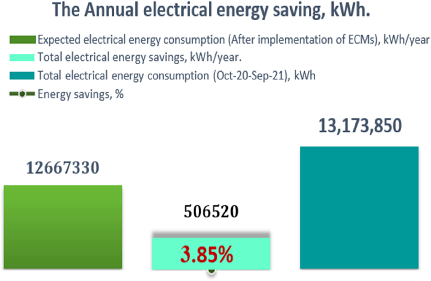
Annual electrical energy saving in kWh.
Footnotes
Acknowledgments
The authors extend their appreciation to the Deanship of Scientific Research at King Khalid University (KKU) for funding this research through the Research Group Program Under the Grant Number:(R.G.P.2/513/44).
Author contributions
Conceptualization, MAHS, SC, SS, CL, YZ; formal analysis, MAHS, SC, SS, CL, YZ; investigation, MAHS, SC, SS, CL, YZ; writing – original draft preparation, MAHS, SC, SS, CL, YZ; writing – review and editing, SS, AK, DK, MA, JL; supervision, SS, AK, DK, MA, JL; project administration, SS, AK, DK, MA, JL; funding acquisition, SS, AK, DK, MA, JL. All authors have read and agreed to the published version of the manuscript.
Declaration of conflicting interests
The author(s) declared no potential conflicts of interest with respect to the research, authorship and/or publication of this article.
Funding
The author(s) disclosed receipt of the following financial support for the research, authorship and/or publication of this article: This work was supported by the King Saud University, (grant number R.G.P.2/513/44). The authors extend their appreciation to the Deanship of Scientific Research at King Khalid University (KKU) for funding this research through the Research Group Program Under the Grant Number: (R.G.P.2/513/44).