
Abstract
The small-scale roadway model is often used in the fine simulation of mining engineering. The determination of the structure and load conditions of the model has an important influence on the accuracy of the simulation. In this paper, a large-scale stratum model and a small-scale roadway model are established by using finite element method. The optimal loading mode of the roadway model and its applicability under different roof-sidewall stiffness ratios are studied. The simulation accuracy of the roadway model is quantitatively evaluated by comparing the distribution laws of stress field and strain field with those of the stratum models. Under the same roof-sidewall stiffness ratio, the similarity between the simulation results of the roadway model and the stratum model under displacement load is much higher than that under stress load. Under the same load mode, the stress and strain similarity between the stratum model and roadway model increases with the increase of the roof-sidewall stiffness ratio. Furtherly, the simulation application of the roadway drilling pressure relief is carried out. Compared with the large-scale stratum model with small-size elements, the small-scale roadway model under displacement load also shows obvious stress transfer after drilling pressure relief, while it has faster computational efficiency. Finally, a small-scale roadway model simulation method suitable for surrounding rock disaster occurrence mechanism and control is proposed.
Introduction
Coal burst is one of the typical dynamic disasters in the process of deep mining in coal mines. This kind of instantaneous and violent disaster will pose a serious threat to the safety of personnel and equipment (Zhao et al., 2018; Keneti et al., 2018; He et al., 2023) basis of coal burst prevention and control is to study its occurrence mechanism. Scholars have revealed the occurrence mechanism of coal burst from the aspects of physical and mechanical properties, geological structure and engineering disturbance of coal and rock mass (Cai et al., 2020; Mahdi et al., 2022; Pan et al., 2023; Faiasal et al., 2023). The study of the mechanism provides a theoretical basis for the prevention and control of coal burst. However, with the increase of coal mining depth, the frequency and intensity of coal burst increase sharply. In order to ensure the safety of coal mine production, the problem of coal burst in deep roadway needs to be solved urgently.
Numerical model test is an important means for mining disaster mechanism and prevention research. It is often used to study the problems of overlying strata movement and deformation failure, stress field and energy field evolution, roadway surrounding rock support control caused by coal mining. Compared with the laboratory test and field test, the numerical simulation test can simulate the complex stratum structure and stress environment of the mining engineering and solve the difficulty of consuming a lot of manpower, material and financial resources when obtaining the test results. The accuracy of the numerical simulation method is high, and it can also predict and forecast the stability of the mine rock mass. For the study of large-scale stratum model of overlying strata movement in mines, the boundary conditions of top boundary applied stress, lateral boundary constrained normal displacement (also applied stress) and bottom boundary fixed displacement are often used (Wen, 2021). The size effect in mining simulation is also a problem that cannot be ignored. For example, in PFC software simulation, when the ratio of model to particle size L/R is less than 60, the elastic modulus and Poisson ‘s ratio of the model change dramatically with the change of particle size, and the particle size has a great influence on the simulation results (Zhao et al., 2012). Gao et al. (2022) based on the simulation of water jet impact; a small-scale three-dimensional cubic model is established to study the influence of element size on the simulation results. It is pointed out that the fluctuation of the results will occur when the element accuracy is low, so the high-precision element should be used as much as possible. Munjiza et al. (2022) used the finite element discrete element coupling method to study the influence of element size on crack propagation and pointed out that the finer the element division is, the more accurate the gradient change of the plastic stress zone at the crack tip can be described. However, in large-scale engineering problems, the refinement of the element will lead to a sharp increase in its number, and the operation needs to occupy a large amount of CPU, thus affecting the calculation efficiency. Therefore, under the premise of ensuring the calculation accuracy, in order to improve the operation efficiency, the element size of the large-scale numerical model is generally large. For example, Du et al. (2016) established a three-dimensional stratum model with a size of 70 m × 1 m × 70 m, the side length of the element is 0.4 m, and the ratio of the model to the element size is 175. The element size has little effect on the study of overburden movement, and the simulation results are reliable.
Different from the large-scale and large-range mine pressure behavior of overlying strata movement, coal burst is mostly caused by high stress in the roadway. The stress concentration area is generally 5–12 m from the side of the roadway (Song et al., 2014), and pressure relief should not be less than this area. Therefore, if the stratum model for researching overlying strata movement is still used to study the coal burst problem of roadway, the element size is generally too large, which seriously affects the simulation accuracy. For example, in the current drilling pressure relief method, the diameter of the pressure relief hole is generally 150 mm. It is assumed that the working condition in the numerical simulation is a coal seam with a mining height of 4 m. Even if the coal seam is divided into 32 layers of elements, then the size of an element is 125 mm, and the pressure relief hole only accounts for one element. The details of the pressure relief hole are not obvious, resulting in errors in the simulation results, and the comparison of the pressure relief effects under different pressure relief parameters is not obvious. And the method by reducing the size of the element to improve the simulation accuracy will seriously affect the computational efficiency. Therefore, small-scale model is common used to study the disaster and control of roadway surrounding rock. For example, Wen et al. (2013) and Xie et al. (2021) used a three-dimensional model with a side length of less than 30 m to study the pressure relief or gas extraction of surrounding rock. Zhu et al. (2022), Zhang et al. (2018) and Zhu et al. (2008) used a small model less than 1 m to study the drilling or bolting of deep roadways. Compared with the large-scale stratum model, the load mode of the small-scale roadway surrounding rock model is not clear, and the existing small-scale model has both stress load and displacement load. Fan et al. (2019), Nian et al. (2022) and Zhu et al. (2013) applied stress loading on the upper boundary of the model to carry out numerical simulation of roadway surrounding rock. Li et al. (2022), Wang (2005) and Yuan et al. (2022) applied displacement load on the upper boundary of the small-scale model to study the properties of surrounding rock, anchorage body and drilling pressure relief of deep surrounding rock. There is no unified conclusion on the influence and selection of different load modes on the simulation results, resulting in less application of small-scale numerical models for roadway surrounding rock disasters such as coal burst.
Therefore, exploring the applicability of different load modes in the roadway surrounding rock model, and avoiding the simulation error caused by the mode in the small-scale model can ensure the calculation accuracy which is helpful to expand its application in the fine study of mine problems. In this paper, by comparing the distribution law of stress field and strain field between large-scale stratum model and small-scale roadway model, the simulation accuracy of roadway model under two different modes namely stress load and displacement load is quantitatively evaluated, and the simulation application of roadway drilling pressure relief is carried out.
Numerical simulation and evaluation method
Research route
The influence range of underground mining is large, and the numerical simulation mainly adopts the large-scale overlying strata movement model for research. This research method is relatively mature and the research results are credible. If the large-scale stratum model is used to study the problem of mine refinement, it will inevitably bring about a surge of elements while refining the elements, which will affect the computational efficiency (Munjiza et al., 2002). The roadway model has obvious advantages in the fine study of the mine pressure behavior of the local surrounding rock structure of the mine. It can not only make the element division of the research object more precise, but also ensure the computational efficiency of the simulation.
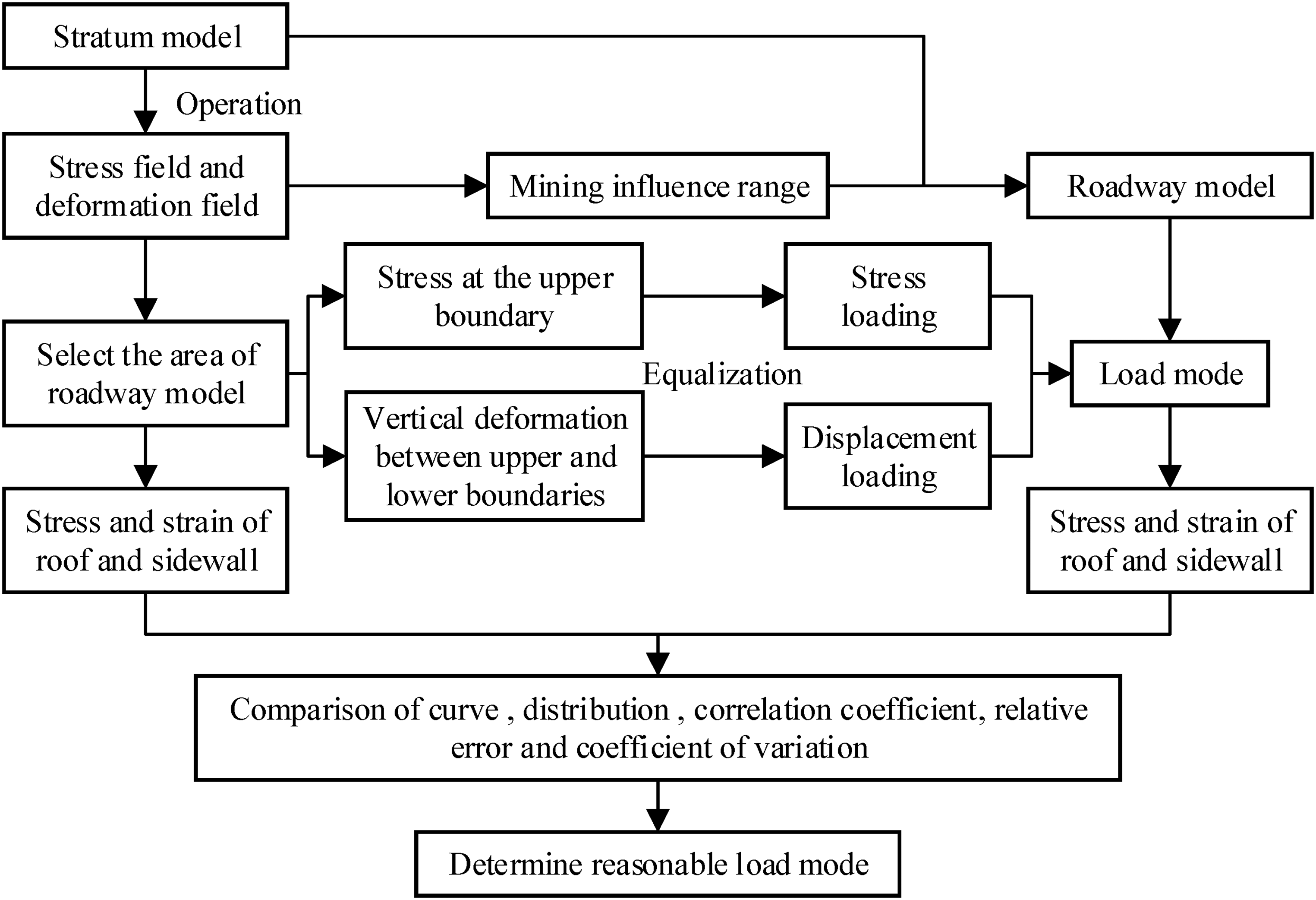
The commonly used load modes in the numerical simulation of mining engineering are stress load and displacement load. The load mode in the stratum model is usually stress load. However, there is no unified conclusion on the load mode in the roadway model. Some scholars use stress load (Zhu et al., 2013; Fan et al., 2019; Nian et al., 2022), and others use displacement load (Wang, 2005; Li et al., 2022; Yuan et al., 2022). Therefore, the determination of the load mode in the roadway model is an important factor affecting the accuracy of the results. In this paper, the simulation results of large-scale stratum model are used as reference standards to measure the rationality of different load modes of small-scale roadway model. By comparing the stress field and strain field data of the roadway model under different load modes with the stratum model, the rationality of the load mode of the roadway model is reasonably evaluated from the aspects of correlation and error of the simulation data. Figure 1 is the technical route, and the specific route is as follows:
Technical route.
Firstly, establish one large-scale stratum numerical model by using finite element method, and apply boundary conditions and loads to the stratum model. Operate the numerical model, and analyze its stress field and deformation field. According to the mining influence range, determine the surrounding rock range of the small-scale roadway model. Since the load and structure of the stratum model are symmetrical about the central axis of the roadway, so coal seam, siltstone roof and mudstone floor on the right side of the stratum model are selected as the simulation range of the roadway model.
Then, apply boundary conditions and loads to the roadway model. Similar to the stratum model, the horizontal displacement is constrained on the left and right boundaries of the roadway model, and the load condition is determined according to the calculation results of the stratum model, that is, the vertical stress at the upper boundary of the siltstone roof is exported and averaged as a stress load applied to the upper boundary of the roadway model. Similarly, the vertical deformation between the upper boundary of the siltstone roof and the lower boundary of the mudstone floor in the stratum model is exported and averaged, and then applied as a displacement load to the upper boundary of the roadway model. The above stress load and displacement load are applied and compared, respectively.
Finally, export the stress and strain of the siltstone roof and coal seam area in the stratum model and the roadway model. The field data of the roadway model under different load modes are compared with that of the stratum model. The influence of load modes on the simulation results of the roadway model is analyzed by correlation coefficient, relative error and coefficient of variation.
Simulation scheme
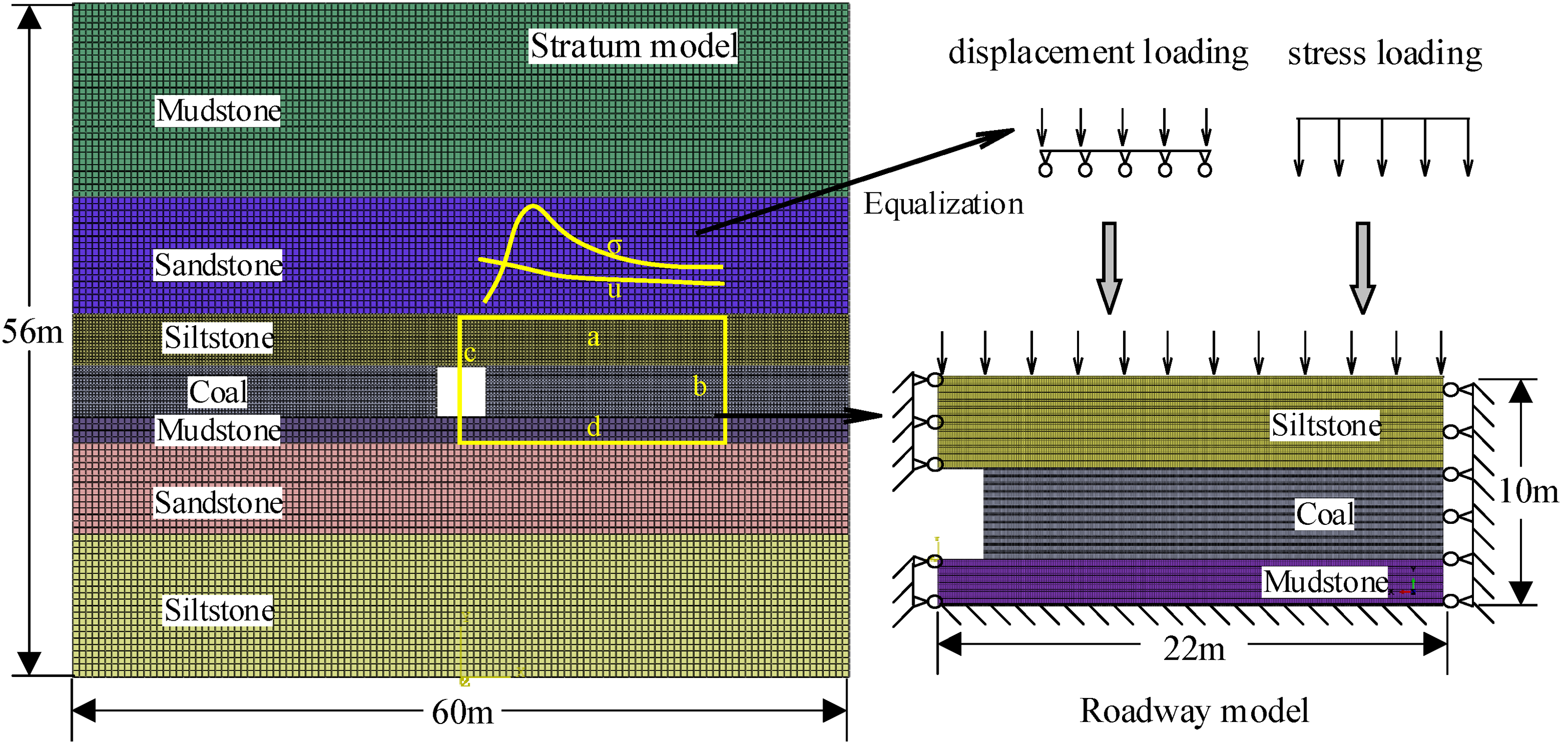
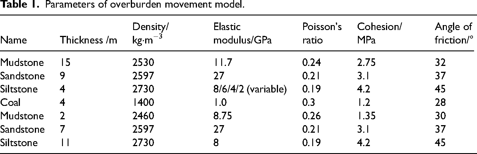
In this paper, ABAQUS software is used for research. The stratum model is a two-dimensional model of 60 m × 52 m, and the roadway size is 4 m × 4 m, as shown in Figure 2. Mohr–Coulomb yield criterion, Hoek–Brown yield criterion and Drucker–Prager yield criterion are commonly used constitutive models in rock mechanics simulation. Both the Mohr–Coulomb criterion and the Hoek–Brown criterion ignore the influence of the intermediate principal stress, and there is inevitably a large deviation between the interpretation of the yield or failure of the surrounding rock and the actual situation. The Drucker–Prager criterion introduces the influence of the intermediate principal stress, which makes the solution to such problems more realistic (He et al., 2017). Under the action of abutment pressure, the weak rock strata in the mine are usually shear failure (Zhang, 2023). The Drucker–Prager failure criterion and shear damage model are used to simulate coal and rock. The thickness and mechanical parameters of rock strata come from the data of Tangkou Coal Mine of Yao's work (Yao et al., 2020) and are simplified, as shown in Table 1. In the stratum model, the stress load is applied to the upper boundary of the model, and the value is 26 MPa. The bottom boundary adopts fixed constraints, and the left and right sides of the boundary constrain horizontal displacement.
Model diagram.
Parameters of overburden movement model.
In order to ensure the accuracy of the calculation results, the element independence test is carried out on the roof and sidewall before the stratum model is meshed. Since the thickness of the roof and the sidewall is consistent, the element size of the two is consistent. The ratio of the roadway height to element size in the stratum model is set to be 4, 8, 16, 32, 64, 128, and 256, respectively, and the calculated vertical stress of sidewall is output. The calculation result of the model with a ratio of 256 is the benchmark, and the relative error is obtained with the other six groups, respectively. Figure 3(a) shows the relative error of the stratum with different element sizes. When the ratio of roadway height to element size is greater than 32, the relative error is below 2%, and the relative error does not change much with the increase in the ratio. Therefore, the ratio of roadway height to element size of the stratum model is chosen to be 32. The element size of the coal seam and the siltstone roof is 0.125 m and the element size of the other rock layers is 0.25 m. The total number of the elements is 71,936.
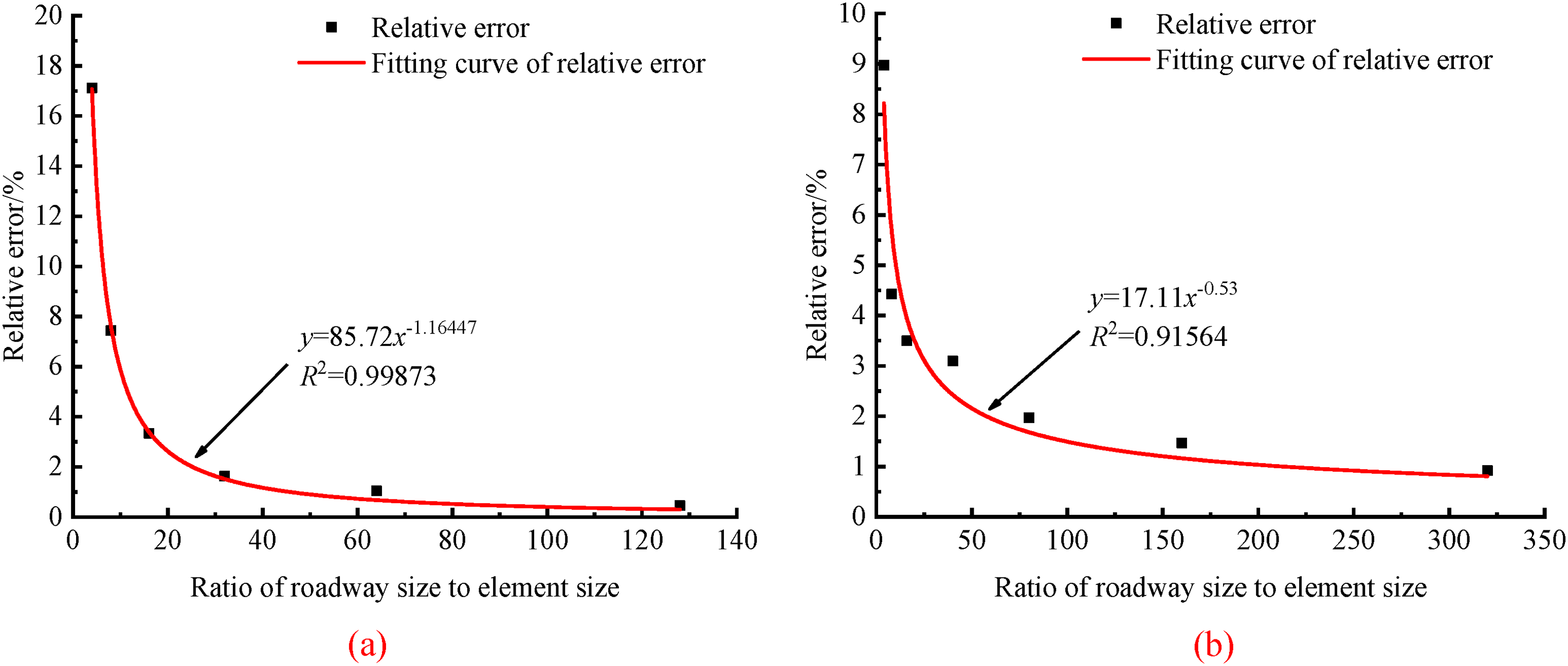
The error curves of (a) stratum model and (b) roadway model with different elements sizes.
The roadway model is established according to the stratum model, and it is two-dimensional, including coal seam, siltstone roof and mudstone floor, with a size of 22 m × 10 m. The constitutive model and material parameters are consistent with that of the stratum model. Two loading schemes on the upper boundary of the roadway model are designed, namely stress load and displacement load, and the value of the stress and displacement are determined from the yellow box selection area in the stratum model. The value determination method of the stress load is as follows: the vertical stress at the survey line a in the stratum model is exported, and its mean value is the value of the stress applied to the upper boundary of the roadway model. The value determination method of the displacement load is as follows: the relative vertical deformation between the measuring lines a and d of the stratum model is exported, and its mean value is the value of the displacement applied to the upper boundary of the roadway model. The horizontal displacement values at the measuring lines b and c of the stratum model are very small. Therefore, the left and right sides of the roadway model constrain the horizontal displacement, and the bottom is fixed.
In the roadway model, the element division is more detailed than the stratum model. The element independence test is carried out too, and the test result is shown in Figure 3(b). When the ratio of roadway height to element size is greater than 60, the relative error is below 2%. Therefore, in the roadway model, the ratio of roof height to element size is set to be 80, and the element size is 0.05 m. The ration of coal seam height to element size is set to be 160, and the element size is 0.025 m. The total number of the element is 180,800.
The loading of the roof to the roadway is derived from the roof settlement caused by mining. The roof stiffness is different, and the roof settlement deformation is also different, which will produce different load modes for the coal seam of the roadway. Therefore, in order to comprehensively consider the influence of roof stiffness and upper boundary load modes of the roadway model, four simulation schemes of roof-sidewall stiffness ratio are designed. The roof stiffness change is realized by changing the elastic modulus of siltstone. The elastic modulus is set to 2 GPa, 4 GPa, 6 GPa and 8 GPa, respectively, and the corresponding roof-sidewall stiffness ratio is 2, 4, 6 and 8, respectively. Two load modes of stress load and displacement load are set up for the roadway model under each roof stiffness.
Data contrast method
The roadway model is derived from the stratum model, and the meaning of the roof and the roadway area in the two models is the same. The stress field and strain field data of the roof and coal seam in the stratum model and the roadway model are exported, respectively. The accuracy of the simulation results of the roadway model is quantitatively evaluated by three indexes: correlation coefficient r, relative error δ and variation coefficient cv.
The correlation coefficient is used to measure the degree of linear correlation between two variables (x and y). The expression is Formula (1):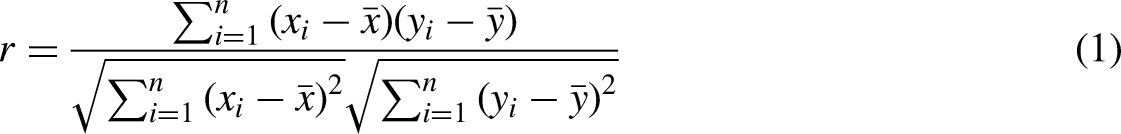
Results and analysis
Vertical stress field of roof
When the roof-sidewall stiffness ratio is 8, the vertical stress curves of the roof of the stratum model and the roadway model are shown in Figure 4. The vertical stress distribution of the stratum model and the roadway model under displacement load have obvious similarity, both of which increase first and then flatten. The vertical stress of the roadway model under stress load shows obvious differences. The stress in the upper part of the roof is approximately linearly distributed, while the stress in the middle and lower parts increases first, then decreases, and then flattens.
Vertical stress curve of the roof with a stiffness ratio of 8.
When the roof-sidewall stiffness ratio is 8, the vertical stress field of the roof of the stratum model and the roadway model is shown in Figure 5. The roof stress at the coal wall of the roadway is low. As the distance grows further from the coal wall, the roof stress increases gradually (Cheng et al., 2022; Tian et al., 2022). In consistence with the stress curves, the low stress area of the stratum model and the roadway model under displacement load is near the sidewall, and the high stress area is in the deep part. Although the low stress area of the roadway model under stress load is also near the sidewall, the stress value is larger and its area is smaller. The high stress area of roadway model under stress load occupies for more than 80% of the roof, which is obviously different from the other two models.
Roof vertical stress field of (a) the stratum model, (b) roadway model under displacement load and (c) roadway model under stress load.
The correlation coefficient, relative error and error variation coefficient of the vertical stress between the stratum model and roadway model are shown in Figure 6. The stress correlation coefficients of the roadway model under stress load are all below 0.6. Under this condition, the correlation between the stratum model and the roadway model is poor. Under displacement load, only the correlation coefficient of roadway model with stiffness ratio of 2 is 0.78, and that of the remaining models is above 0.91. The vertical stress relative error of the roadway model under stress load is 37%–57%, and the relative error of the model under displacement load is 22%–43%. The relative error of the roadway model under displacement load is significantly lower than that under stress load. The variation coefficient is larger when the stress load is applied on the roadway model, reaching 1.34 when the stiffness ratio is 2. Compared with the stress load mode, the variation coefficient of the roadway model under displacement load is reduced to less than 0.21. The above analysis shows that the vertical stress field similarity between the stratum model and the roadway model under displacement load is higher, the error is smaller, and the simulation result is more accurate.
Comparison chart of vertical stress of roof.
Vertical stress field of sidewall
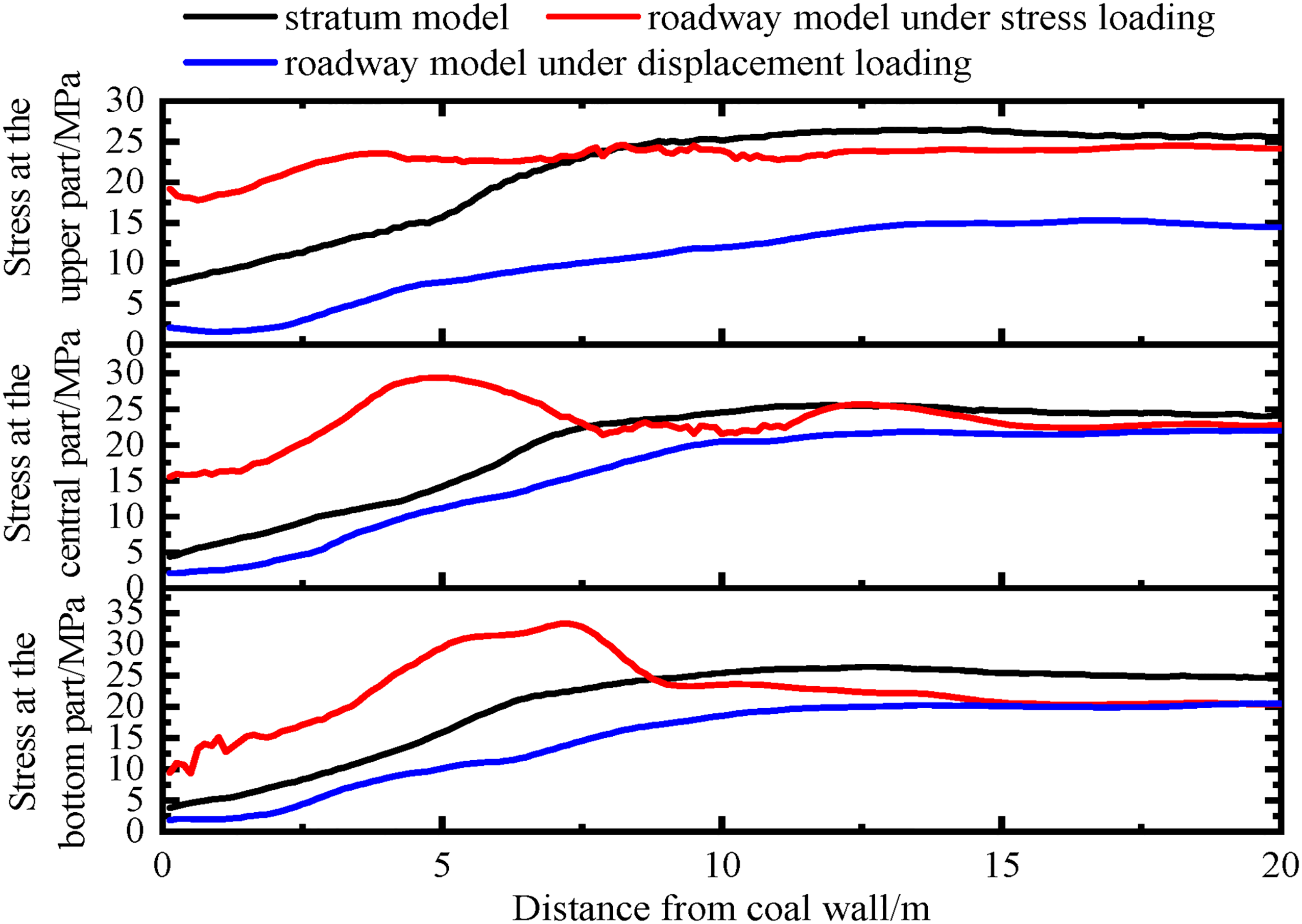
When the roof-sidewall stiffness ratio is 8, the vertical stress curves of the roadway sidewall of the stratum model and the roadway model are shown in Figure 7. The vertical stress distribution of the roadway sidewall of the stratum model and the roadway model under the displacement load is highly consistent, showing a trend of increasing first and then flattening. The numerical differences in other stags are small except for the transition section of the curves rising and flattening. Under the stress load, the vertical stress of the roadway sidewall of the roadway model increases first, then decreases and then flattens, and the numerical difference with the stratum model is very large.
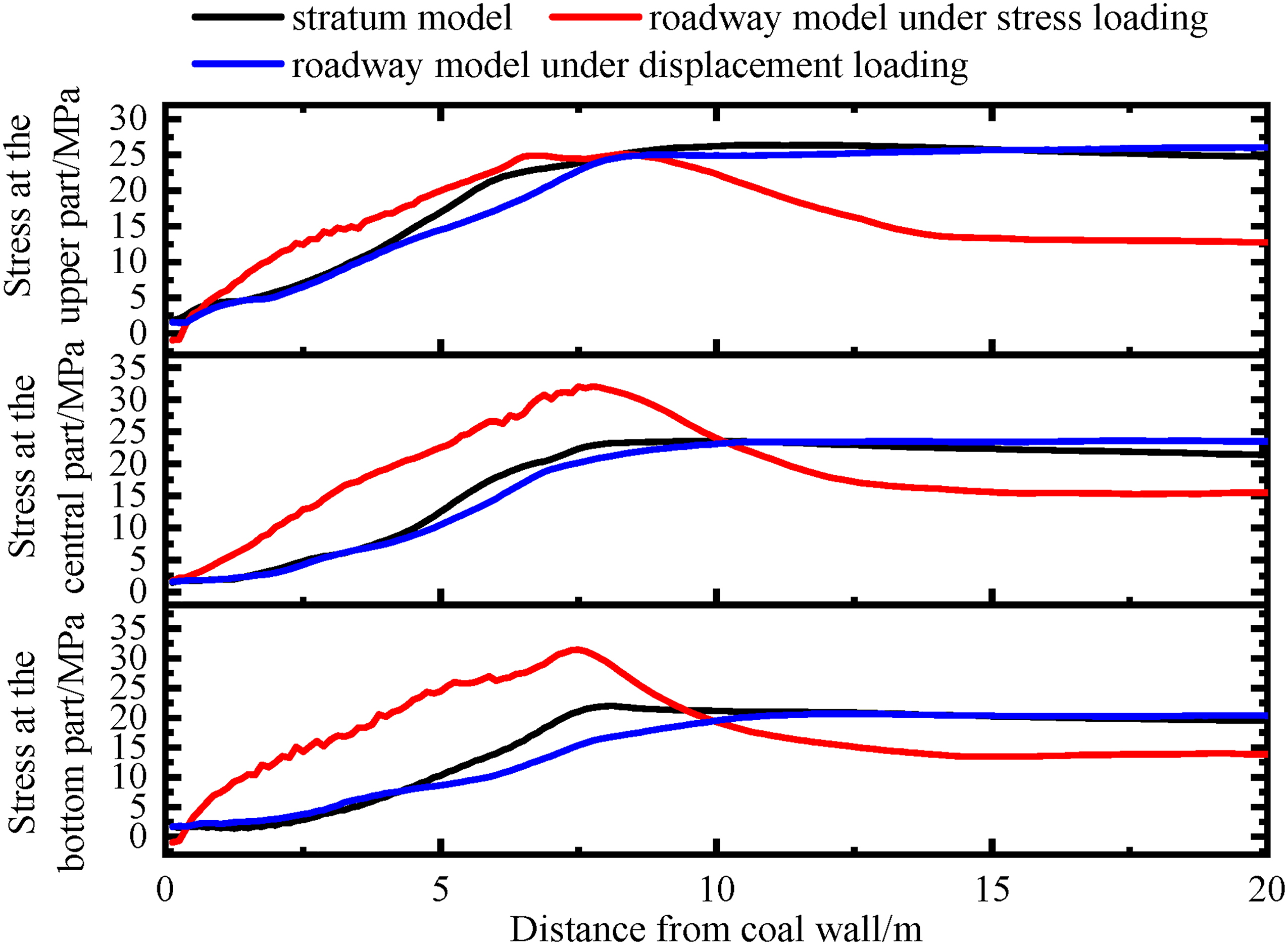
Vertical stress curve of the roadway sidewall with stiffness ratio of 8.
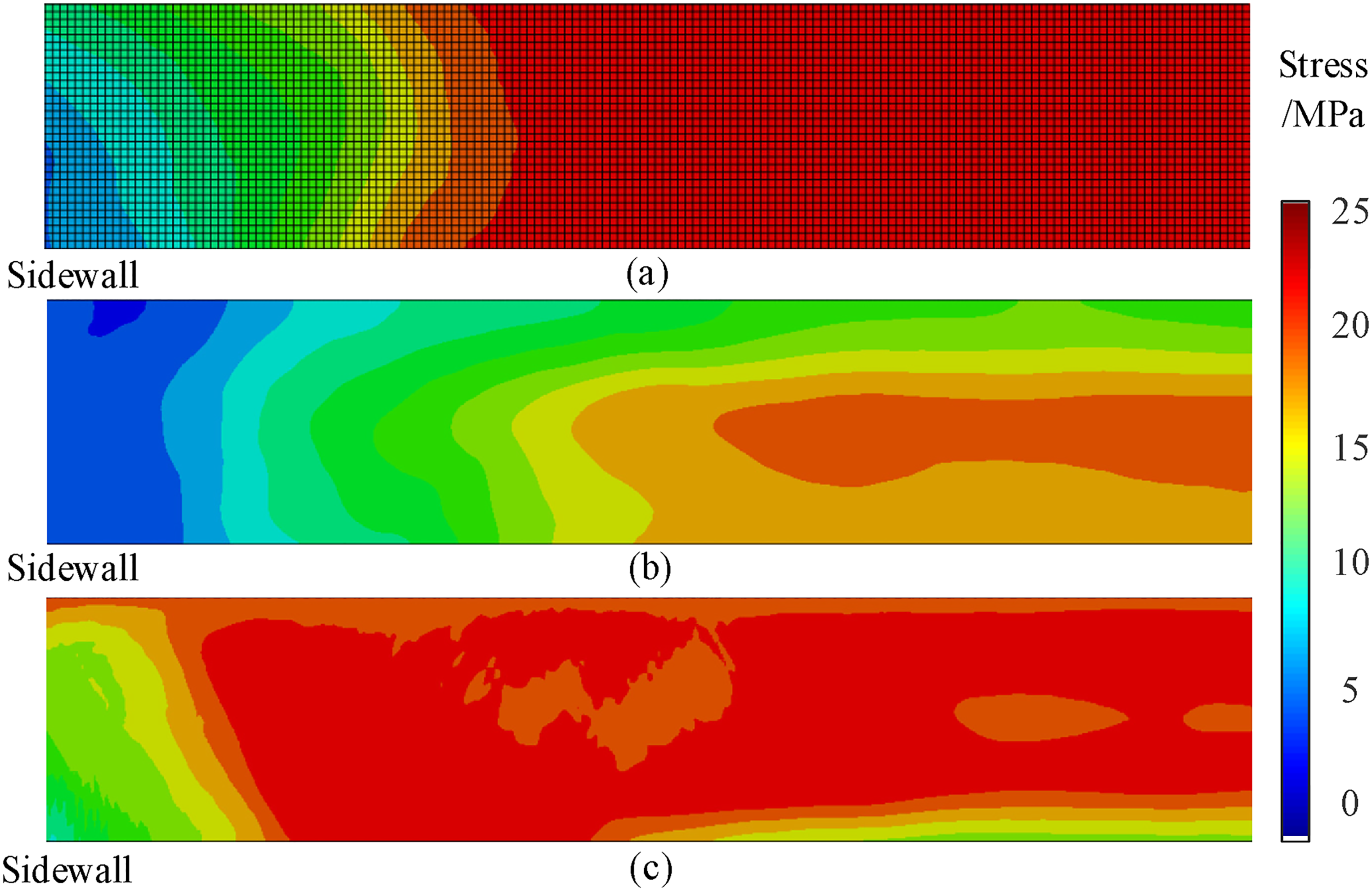
When the roof-sidewall stiffness ratio is 8, the vertical stress field of the roadway sidewall of the stratum model and the roadway model are shown in Figure 8. In the shallow part of the sidewall, the coal stress gradually increases. When it reaches the peak value, it decreases slowly (Shen et al., 2023). Consistent with the stress curves distribution, the low stress area of the roof of the stratum model and the roadway model under the displacement load is in the lower left corner near the sidewall, which is a fan-shaped distribution, and the high stress area is in the deep side of the roadway sidewall near the roof. Although the low stress area of the roadway model under the stress load is also on the side of the sidewall, the high stress area is on the middle side of the sidewall, which is obviously different from the other two models. The non-uniform settlement characteristics of the roof under the stress load are obvious; especially at the position of the roadway, the suspended roof will have obvious settlement deformation. Under the action of roof settlement loading, the shallow part of the coal sidewall is fractured and its bearing capacity is reduced. At this time, there is obvious stress transfer in the sidewall, and the stress concentration is obvious at the middle part of the sidewall. Compared with stress load, the roof settlement deformation under displacement load is relatively uniform. Although the shallow part of the sidewall is also in a plastic state with low stress, and the stress concentration occurs at the depth of the sidewall, but the stress concentration is relatively weak.
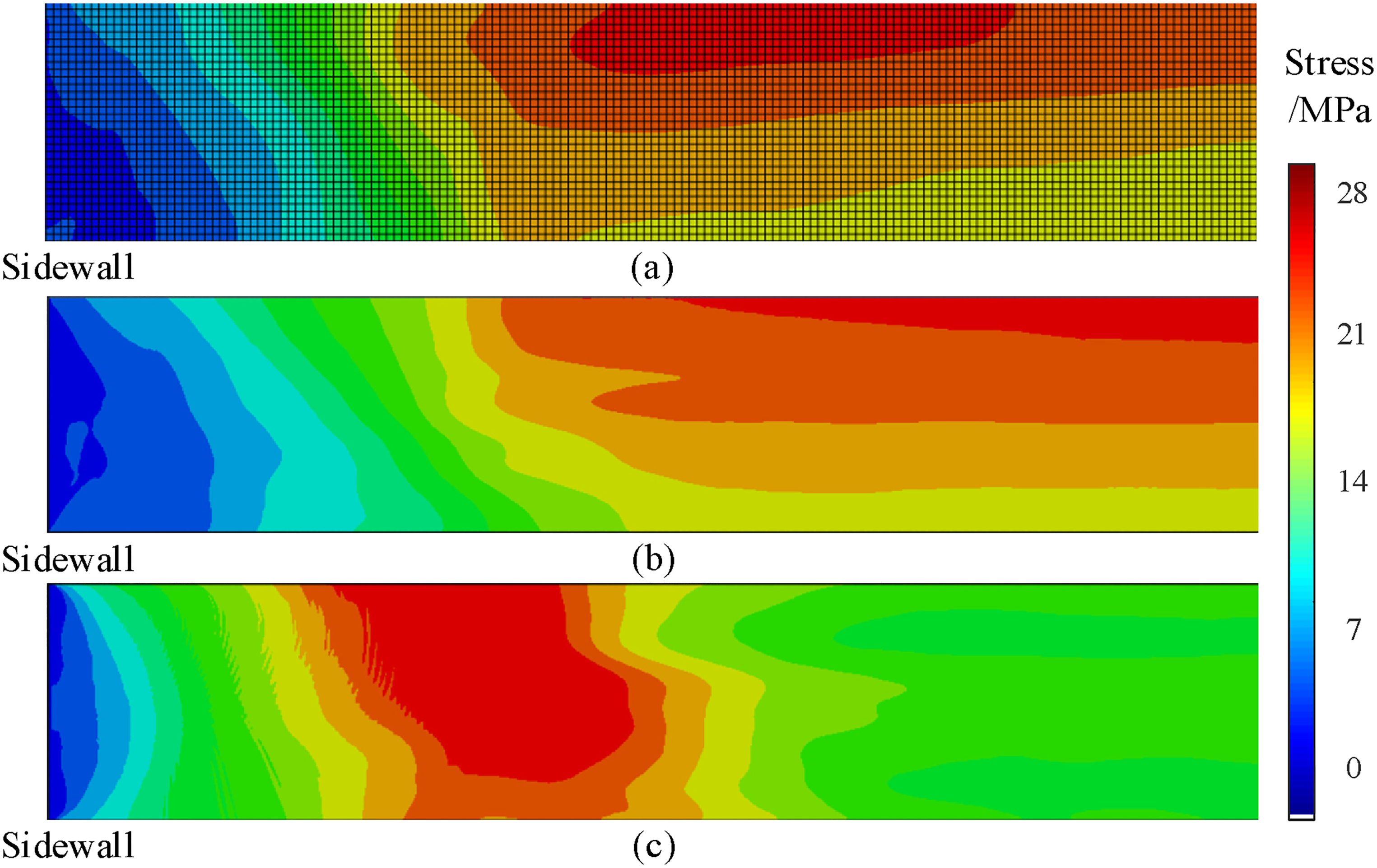
Sidewall vertical stress field of (a) the stratum model, (b) roadway model under displacement load and (c) roadway model under stress model.
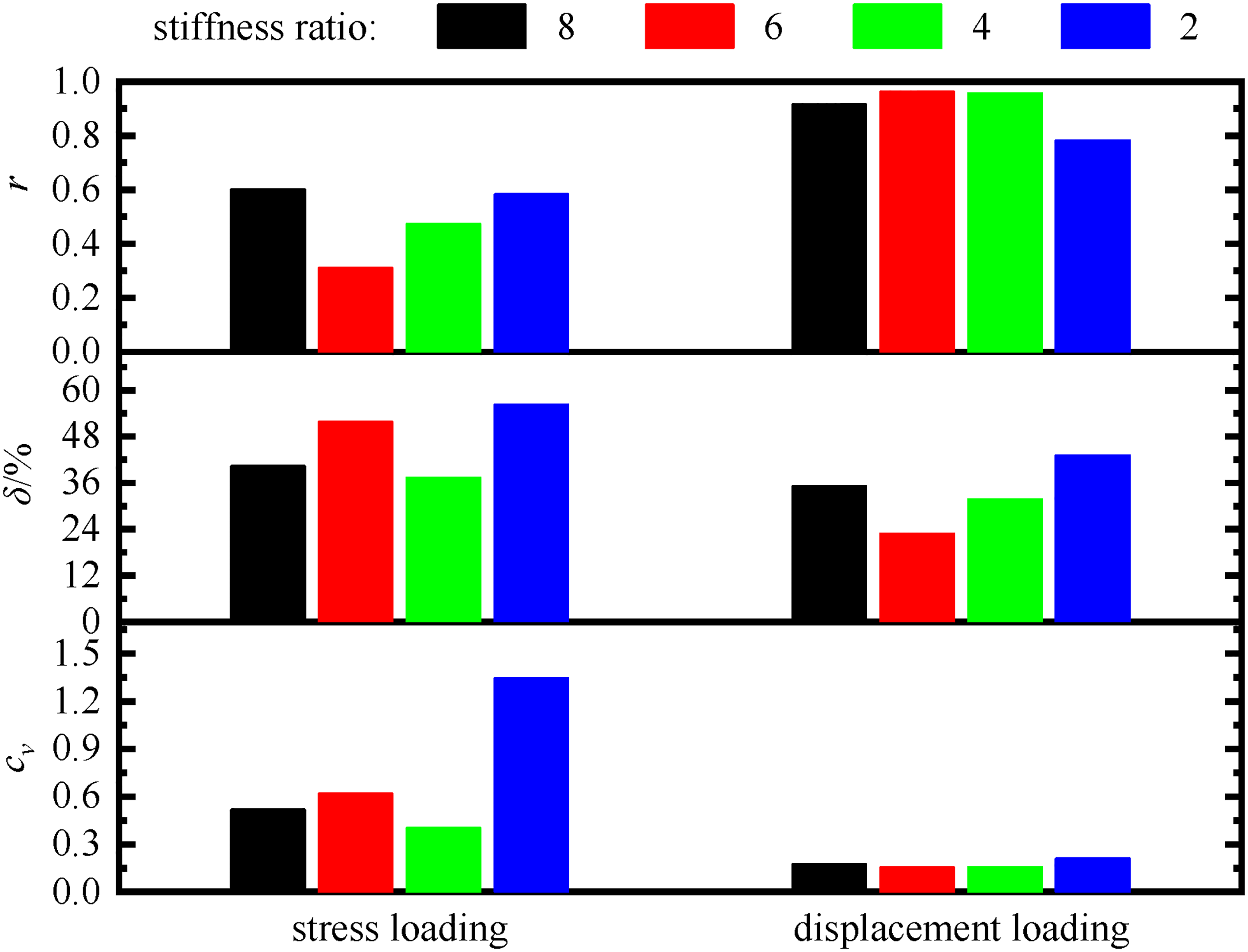
The correlation coefficient, relative error and error variation coefficient of the vertical stress between the stratum model and roadway model are shown in Figure 9. From the perspective of correlation coefficient, the roadway model under stress load is 0.62 when the stiffness ratio is 2, the other three groups are below 0.44, and the correlation coefficient of the roadway model under displacement load is above 0.94. The relative error of roadway model under stress load is more than 48%, and the error is far more than the normal level. And the roadway model under displacement load is 50% when the stiffness ratio is 2, 15% when the stiffness ratio is 4, and less than 10% in the other two cases. The coefficient of variation is larger when the stress load is applied, which is above 0.9 under the stiffness ratio of 8 and 2, and the others are between 0.53 and 0.6. The variation coefficient of the roadway model under displacement load is less than 0.19, and it is less than 0.1 when the stiffness ratio is 4 and 2. The error between the stratum model and the roadway model under displacement load is small and stable.
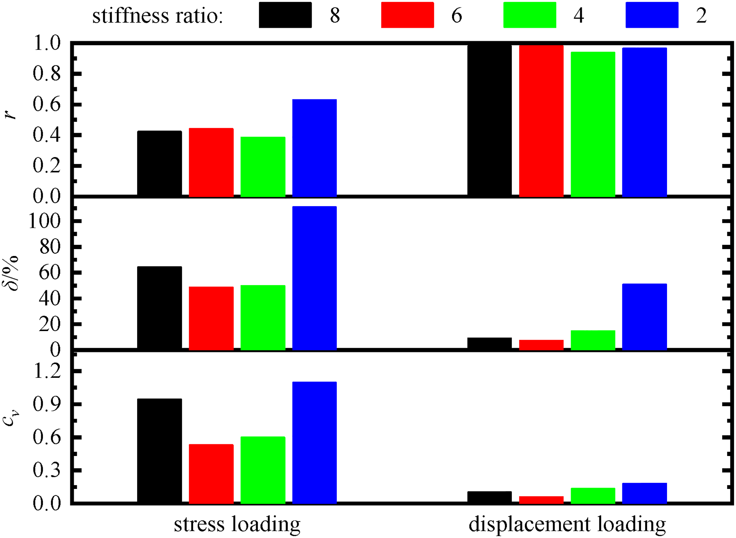
Comparison chart of vertical stress of roadway sidewall.
Vertical strain field of sidewall
When the roof-sidewall stiffness ratio is 8, the vertical strain curves of the roof of the stratum model and the roadway model are shown in Figure 10. The vertical strain trend of the roadway side of the stratum model and the roadway model is similar, that is, it shows a trend of increasing first, then decreasing, and then flattening. The vertical strain of the roadway model under the displacement load is closer to the stratum model in value, while the vertical strain of the shallow part of the roadway model under the stress load is obviously larger.
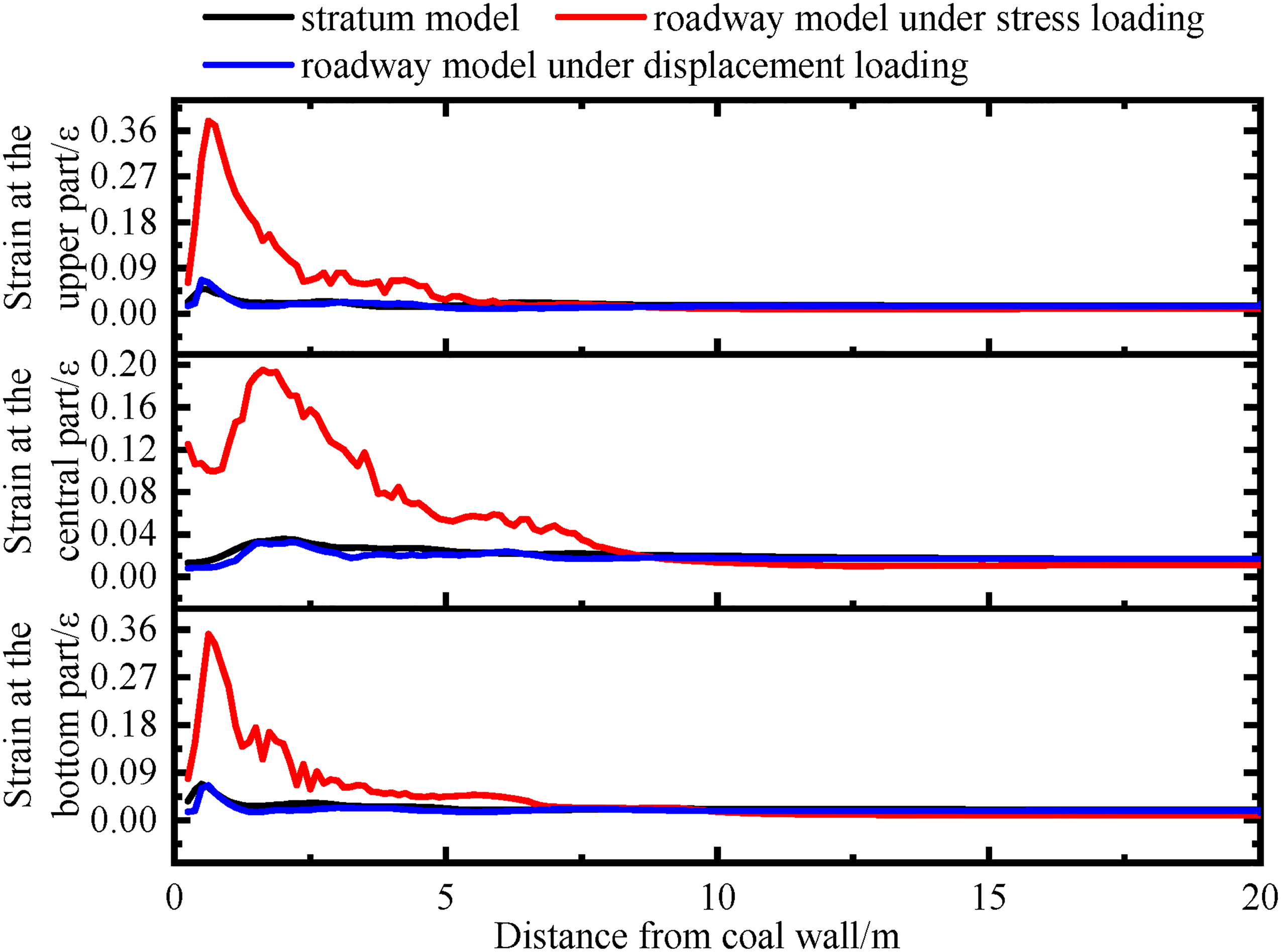
Vertical strain curve of the roadway sidewall with stiffness ratio of 8.
When the roof-sidewall stiffness ratio is 8, the vertical stress field of the roof of the stratum model and the roadway model is shown in Figure 11. Consistent with the strain distribution curves, the high strain area of the sidewall of the stratum model and the roadway model under displacement load is in the upper left corner and the lower left corner near the sidewall, showing a triangular distribution, and a low strain area appears in the middle. With the increase of the distance from the sidewall, the vertical strain increases first and then decreases, and the strain value in the internal area of the roadway sidewall is at a medium level. The high stress area of the roadway model under the stress load is also near the sidewall, but the distribution range is larger, and the proportion is much higher than the other two models.
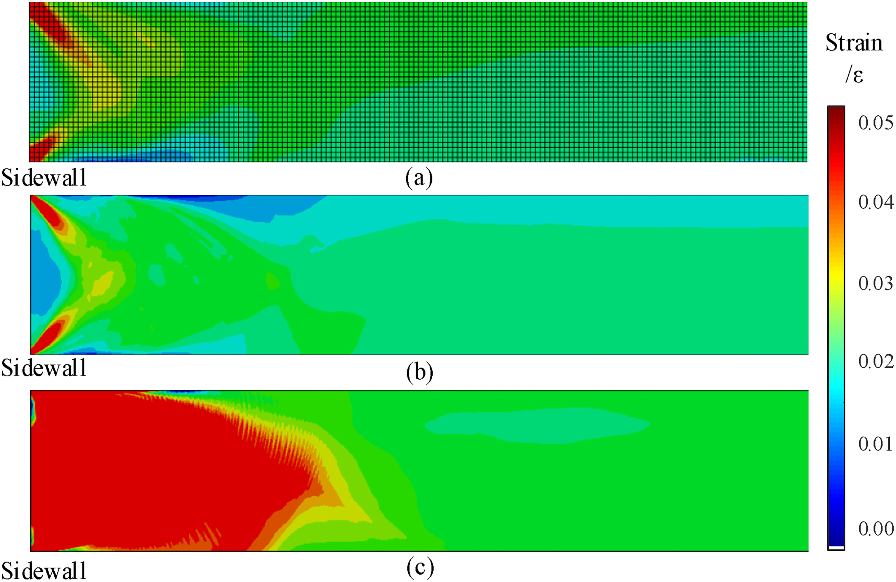
Sidewall vertical strain field of (a) the stratum model, (b) roadway model under displacement load and (c) roadway model under stress model.
The correlation coefficient, relative error and error variation coefficient of the vertical strain between the stratum model and roadway model are shown in Figure 12. The correlation coefficients of the roadway models of the four roof stiffness ratios under displacement load are all around 0.74, and the correlation is not high. However, when it is under stress load, only the correlation coefficient of the stiffness ratio of 2 is 0.73, and the other three groups are below 0.6. The relative error between the stratum model and the roadway model under stress load is more than 120%. When the roadway model under displacement load, only the stiffness ratio of 2 is 38%, and the other three groups are below 15%. The coefficient of variation is larger when the roadway model is under stress load, showing a decreasing trend with the decrease of stiffness ratio, and it still reaches 4.04 when the stiffness ratio is 2. When the roadway model is under displacement load, it is between 0.18 and 0.21.
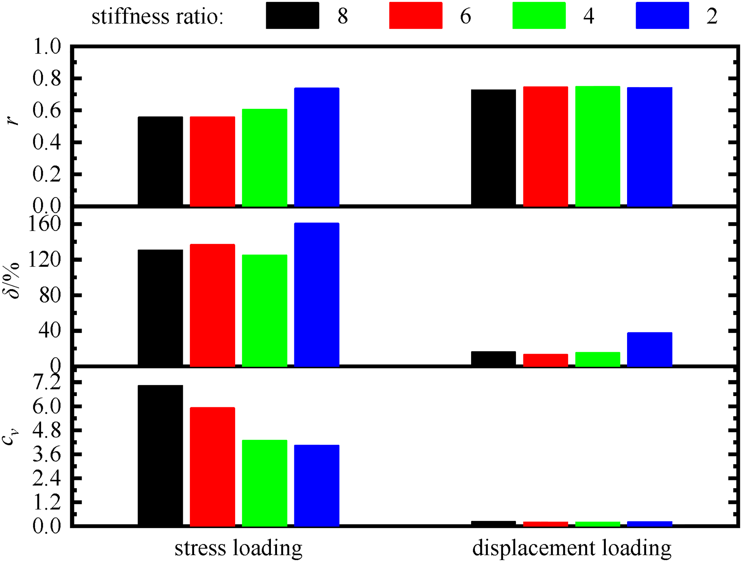
Comparison chart of vertical strain of roadway sidewall.
According to the comparison of roof vertical stress, vertical stress of roadway side, vertical strain of roadway side and horizontal strain of roadway side between stratum model and roadway model, it can be concluded that: Under the same roof-sidewall stiffness ratio, the fit between the data and the stratum model when the displacement load is applied to the roadway model is much higher than that when the stress load is applied. Under the same load condition, the larger the stiffness ratio, the higher the fit.
Model application
According to the comparative analysis, the difference between the roadway model under displacement load and the stratum model is small. In the following work, the applicability of the roadway model is further verified by the simulation of roadway drilling pressure relief.
Establishment of the model
The stratum model is a three-dimensional model of 60 m × 6 m × 52 m. The roadway size is 4 m × 4 m. The pressure relief hole with a diameter of 150 mm and a depth of 18 m is set on the roadway sidewall. The Drucker–Prager failure criterion and shear damage model are used in the constitutive relationship. The thickness of the rock layer and the specific mechanical parameters are shown in Table 1. The roof-sidewall stiffness ratio is 8.
In order to compare the effects of element size and number on simulation results and efficiency, two stratum models with different element sizes are established. In the stratum-I model, the element size of coal seam and siltstone roof and mudstone floor is 0.5 m, with a total of 160782 elements. The element size of coal seam in the stratum-II model is 0.05 m; the element size of siltstone roof and mudstone floor is 0.25 m, with a total of 13369544 elements. The element around the pressure relief hole is divided as shown in Figure 13. A uniform stress of 26 MPa is applied to the top of the stratum model, and the bottom boundary is fixedly constrained. The front and rear sides, the left and right sides of the boundary constrain the horizontal displacement.
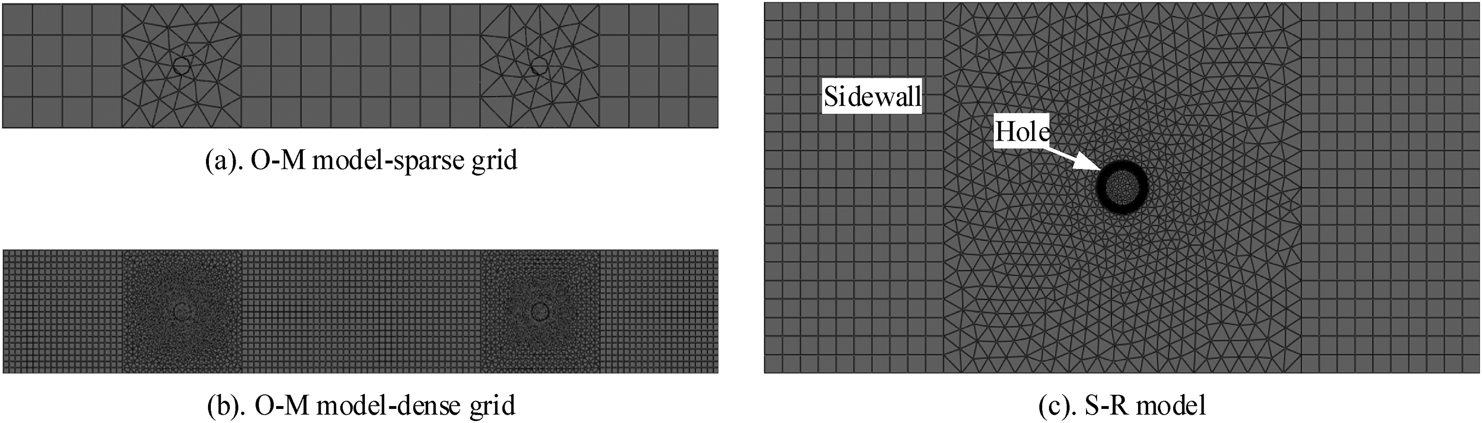
Elements layout around the pressure relief hole of (a) stratum-I model, (b) stratum-II model and (c) roadway model.
The size of roadway model structure model is 22 m × 2 m × 10 m, including siltstone roof, coal seam and mudstone floor. The setting of pressure relief hole, constitutive model and material parameters are consistent with the stratum model. The element size of the floor and roof is 0.25 m, with a total of 16896 elements, and the element size of the coal seam is 0.05 m, with a total of 2854719 elements, which is consistent with that of the stratum-II model. The applying method of the stress load and displacement load on the upper boundary of the roadway model is the same as that in Section 1.2.
Comparison of pressure relief effect
The number of elements in the numerical model is very important to the operation efficiency. The size of the model and the size of the element are directly related to the number of elements. In the stratum-I model with large-size elements, the operation time is about 9 hours. When the element size is decreased in stratum-II model, the operation time is increased to 56 hours. In the roadway model, the element size is consistent with that of the stratum-II model, and the operation time is only 13 hours, which shows faster operation efficiency.
The sidewall vertical stress of the stratum model and the roadway model before and after the drilling pressure relief is compared, as shown in Figure 14. Compared with the stress before pressure relief, the stratum-I model has no pressure relief effect when using large-size elements, and the stress in the middle and deeper section of the roadway is slightly increased. In the roadway model under stress load, there is no pressure relief in the shallow part of the sidewall. The stratum-II model with small-size elements and the roadway model under displacement load have obvious pressure relief effect, and the effect is almost the same. The sidewall vertical stress is reduced to 50%, and the pressure relief effect of these two models is consistent with the research results of Wang et al. (2017) and Gu et al. (2022).
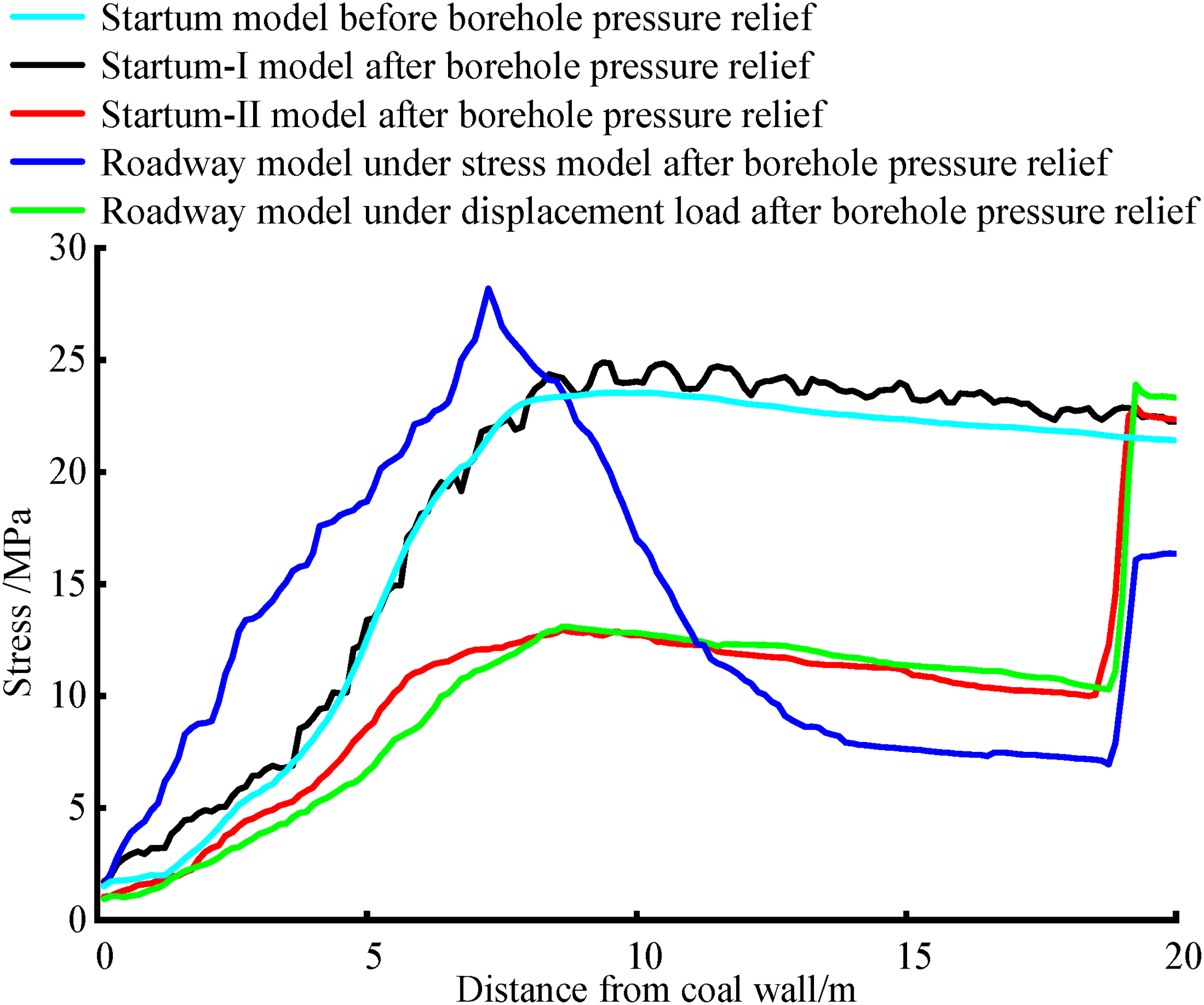
Vertical stress curve of the roadway sidewall after borehole pressure relief.
The sidewall vertical stress field of the stratum model and the roadway model after borehole pressure relief is shown in Figure 15. In the stratum-I model with large-size elements, there is a stress concentration area in the middle and rear sections of the pressure relief hole, which is serrated and does not show the pressure relief effect. In the stratum-II model with small-size elements, the stress near the pressure relief hole is significantly reduced, and the pressure relief effect is obvious. In the roadway model under displacement, the pressure relief effect of the pressure relief hole is obvious, which is consistent with the stress distribution of the stratum-II model. When the stress load is applied, although the stress near the deep pressure relief hole of the roadway is lower than that of other areas, there is obvious stress concentration in the front and middle parts, and the stress concentration distribution near the pressure relief hole is larger, and there is no proper pressure relief effect.
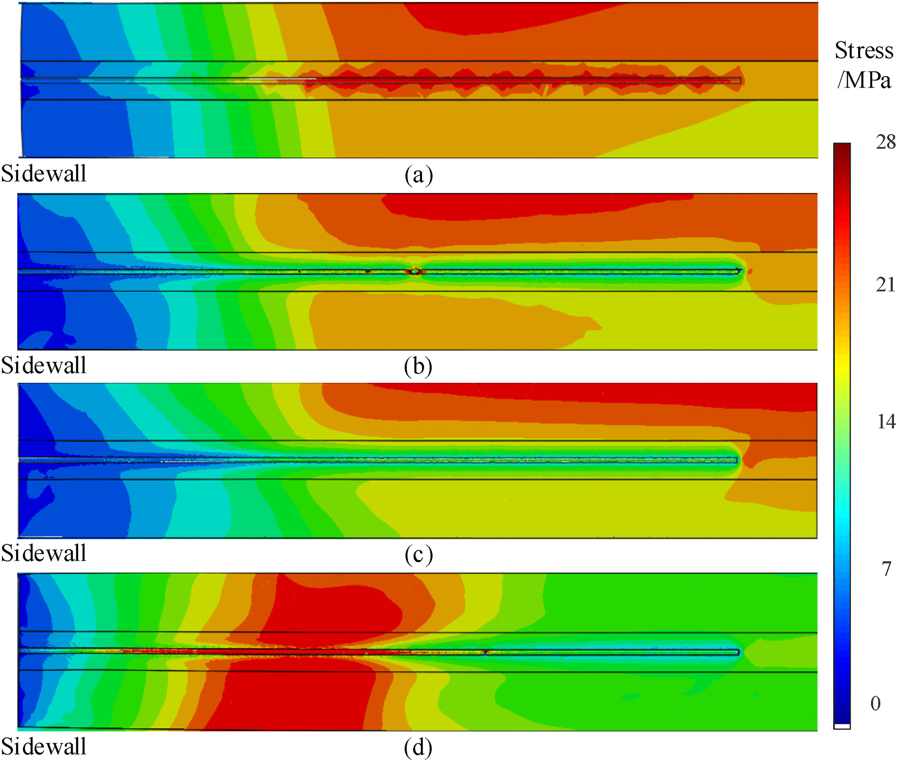
Roadway sidewall vertical stress field of (a) stratum-I model, (b) stratum-II model, (c) roadway model under displacement load and (d) roadway model under stress load
Simulation method of roadway model
According to the comparative analysis of the stratum model and roadway model, the applicability of the roadway model under different load modes in the fine study of mine problems is determined, and a three-dimensional borehole pressure relief roadway model is established for example verification. It is concluded that when the roadway model under displacement load can be used to replace the stratum model for simulation, the simulation results between these two models are almost the same, which ensures the efficiency of calculation. A simulation method of roadway model based on stratum model is summarized.
Firstly, based on the engineering problems, establish a large-scale stratum model according to the parameters of each rock stratum and buried depth in the actual mining area. Apply reasonable boundary conditions and loads. The stratum model only needs to include the structure of roadway, goaf and other structures that cause mining influence, and does not need relatively small structures such as drilling and cutting, and the element does not need to be too fine.
Secondly, according to the calculation results of the stratum model, determine the influence range mining of the roadway, so as to select the size of the roadway model reasonably. The roadway model includes roof, coal seam, part of floor and roadway, and the rock parameters should be corresponding to the stratum model. The element size of the roadway model can be reduced according to the engineering problems studied to ensure the refinement of various research objects.
Then, select the corresponding area of the roadway model from the stratum model, and export the vertical deformation between the upper and lower boundaries of the roadway model. After homogenization, apply the displacement to the upper boundary of the roadway model. Other boundary conditions can be reasonably determined according to the research object.
Finally, in view of the engineering problems, the roadway model is used for fine simulation research, such as drilling pressure relief, anchoring support research, etc.
Discussion
In this paper, the application of small-scale roadway model in the fine simulation of mine problems is studied. The simulation accuracy of roadway model under different load modes and different roof-sidewall stiffness ratios was studied. On this basis, the simulation application of the roadway drilling pressure relief is carried out, and the small-scale roadway model simulation method suitable for fine simulation of local surrounding rock disaster occurrence mechanism and control is proposed. In the simulation of mine problems, the commonly used model is a large-scale stratum model. The ratio of the model size to the roadway size is usually more than 10 times (Wei et al., 2023). If the stratum model is still applied in the study of the bolt problem or the borehole pressure relief problem, the ratio difference between the research object and the whole model will not be balanced. For example, in the study of Wei and Zhang (2023), the diameter of the bolt is 34 mm, the width of the model is 36 m, and the ratio is above 1000. Therefore, in the stratum model, if the element number is reduced, the element division of the research object will be rough and the calculation result will be distorted. However, the refinement of the research object will increase the number of elements in the overall model, which greatly affects the operation efficiency (Munjiza et al., 2002). If small-scale models are used in such studies, the proportion between the research object and the overall model can be reduced, thereby reducing the number of elements. However, the small-scale model is usually the scale of the specimen (Zhang et al., 2018; Zhu et al., 2008, 2022), which is not consistent with the engineering background, and the small-scale model of the engineering scale is rarely used. Moreover, in the application of existing small-scale models, there is no unified conclusion on the application of loads. Some scholars use stress load (Nian et al., 2022), and others use displacement load (Li et al., 2022).
The main research object of this paper is the small-scale roadway model. Under the displacement load, the stress and strain are in good agreement with the results of the corresponding area in the stratum model. Different roof-sidewall stiffness ratios have little effect on the simulation results and do not hinder the application of the roadway model for the sidewall problem research. In the simulation application of the roadway drilling pressure relief, the load mode of small-scale model is verified again, and the calculation efficiency and calculation results are compared with the formation model of different element sizes. The roadway model under displacement load not only guarantees the accuracy of calculation results, but also greatly improves the efficiency of calculation. The small-scale roadway model simulation method can provide a new model establishment method for the fine research of mine problems and provides a basis for the application of roadway model.
In this paper, the upper displacement load of the small-scale roadway model is assumed to be uniformly distributed. However, in the field engineering and large-scale stratum model, the displacement load is non-uniform. How to accurately characterize the non-uniform distribution characteristics of the displacement load of the roadway model will be the future research work.
Conclusions
Under the same roof-sidewall stiffness ratio, the similarity between the simulation results of the roadway model and the stratum model under displacement load is much higher than that under stress load. The vertical stress similarity of the sidewall is the highest, and the correlation coefficient under displacement load is above 0.94, and the stress load is below 0.6.
In the example verification, the smaller the element size, the smoother the stress transition between the elements. The roadway model under displacement load shows obvious stress transfer before and after drilling pressure relief, which is consistent with the stratum model under small-scale element, but the computational efficiency of the former is significantly improved.
According to the comparison between the stratum model and the roadway model under different load modes, and after the verification of examples, one method for using the roadway model suitable for the fine research of mine problems is summarized, which can reflect the fine structural details and ensure the efficiency of calculation.
Footnotes
Declaration of conflicting interests
The author(s) declared no potential conflicts of interest with respect to the research, authorship, and/or publication of this article.
Funding
The author(s) disclosed receipt of the following financial support for the research, authorship, and/or publication of this article: This work was supported by the National Natural Science Foundation of China, Shandong Energy Group, Major Program of Shandong Provincial Natural Science Foundation (grant numbers NO.52074167, NO.SNKJ2022BJ01-R27, NO.ZR2019ZD13).