
Abstract
To ensure gas control in the layered mining of extra-thick coal seams in Baijigou Coal Mine—in addition to reducing the loss of coal resources and amount of roadway driving—this article proposes the gob-side entry retention technology of flexible formwork concrete, and retains the 010202 working face four-layered return air roadway as the 010203 working face gas drainage lane. By combining theory and field practice, a flexible formwork concrete wall + anchor cable joint support scheme is proposed to strengthen small coal pillars. Further, the design scheme for the aforementioned framework at the bottom of the layered mining region of an extra-thick coal seam is proposed. Then, field tests are carried out, and the surrounding rock activity law of the double flexible formwork wall entry retention in a layered mining coal seam is obtained. The results show that (i) 010202 the whole process of overburden collapse to stability at the stratified mining face is completed 60--200 m behind the face and (ii) the roadway deformation of the extra-thick coal seam in the Baijigou Coal mine can be divided into four stages, and the mining pressure of the gas drainage roadway basically presents a dynamic change of “pressurized stage – peak stage – stabilized pressure stage”. Based on this, three mechanical stages of roadway deformation are derived: (1) δz< Nmz<< Nwz; (2) Nmz <δz << Nwz; and (3) Nmz <δz< Nwz. Three repeated mining support optimization schemes are provided, one for each stage. Finally, the deformation and damage of the surrounding rock are effectively controlled, and the requirement that the gas drainage roadway is still intact under the influence of the 010203 working face mining is realized. This study has certain reference significance for gob-side entry retention in the bottom layer of stratified mining in extra-thick coal seams.
Keywords
Introduction
Coal resources have always been the main source of energy worldwide. In recent years, with rapid developments in the world economy, the consumption of global coal resources is increasing daily. To improve the coal recovery rate, mine safety, and economic benefits, gob-side entry retention technology has been gradually applied in coal mines all over China, Germany, Poland, the United Kingdom, and other countries (Fan et al., 2014; Gong et al., 2018; Li et al., 2018; Luan et al., 2018a, 2018b; Ning et al., 2017; Shen et al., 2018). The application of gob-side entry retention not only realizes coal pillar-free mining, significantly reduces the loss of coal resources, improves investment efficiency, and prolongs mining life (Anagnostopoulos et al., 2020; He et al., 2017; Tan et al., 2019; Zhao et al., 2018, 2020), but also enables the working face to achieve Y-shaped ventilation, effectively mitigating the issue of gas accumulation in the upper corner (Zhang et al., 2012, 2016). In recent years, many scholars have conducted theoretical and practical research on gob-side entry retention technology, obtaining promising research results. A variety of new gob-side entry retention technologies have also emerged, such as coal gangue walls, high-water content material-filled walls, concrete walls, and a combination thereof (Chang et al., 2018; Li et al., 2016; Zhang et al., 2015). Flexible formwork concrete roadway retention has been widely used as a novel support technology owing to its high support strength, good integrity, and simple construction technique. To a certain extent, it represents the development direction of roadway retention technology along the hollow section (Gu, 2020; Wang et al., 2021).
Under the conditions of a hard roof with strong weighting and rapid subsidence, a new type of artificial composite wall—called the “flexible-hard” combination support—has been proposed, and the gob-side supporting force and permissible compression during gob-side entry retention were determined by establishing a mechanical model (Tan et al., 2015). Huang et al. (2015) proposed a concrete-filled steel tubular column and flexible cushion support technology for gob-side entry retention. Gong et al. (2017a, 2017b) proposed an innovative gob-side entry retention method combining underground backfilling mining technology with gob-side entry retention technology, studying the surrounding rock deformation mechanism of gob-side entry retention with fully mechanized gangue backfilling mining by conducting a simulation experiment on similar materials. According to the geological and mining conditions of the fully mechanized coalface in a steeply inclined coal seam, a suitable roadside backfilling-truss support structure has been proposed, and a mechanical model for the support was established to determine the shear stresses on the roadside filling body once the motion of the roof had been stabilized (Ning et al., 2017). Su et al. (2015) proposed a top coal roof support technology with high-strength prestressed bolts and cable-stayed supports filled with high-strength materials. Wang et al. (2018) introduced key techniques in no-pillar mining with automatically formed gob-side entry retention and applied these techniques in the field. Luan et al. (2018a, 2018b) introduced an innovative approach that included high-strength and lightweight foam concrete, in addition to a mortise and tenon structure hollow block wall for gob-side entry retention; their results showed that the wall structure and parameters are reasonable and could effectively control the roof. For gangue treatment, a gangue wall has been used to seal the goaf, and a real-time remote monitoring system has been developed (Yang et al., 2019). The on-site monitoring results showed that the periodic compressive load of the working face was reduced after roof blasting, and the application of the system was effective.
The aforementioned research results have helped make significant progress in the field of gob-side entry retention technology, which has reference value for the development of the coal industry. However, according to the current data, there are few studies on the mine pressure law and support technology of gob-side entry retention in the middle and lower layers of extra-thick coal seams. In particular, relevant research reports on the use of flexible formwork concrete as the roadside support material in layered roadway retention at the bottom of extra-thick coal seams are rare. Therefore, this study takes the gob-side entry retention of Baijigou Coal Mine as an example, and implements a self-developed flexible formwork concrete gob-side entry retention technology for layered entry retention at the bottom of an extra-thick coal seam. First, combined with the engineering conditions, the flexible formwork concrete wall is used to reinforce small coal pillars for the first time. Second, the support technology for the adopted flexible formwork concrete double-wall entry retention method is also proposed. After the application, the retention roadway is used as the gas drainage roadway to resolve the issue of gas drainage in the four-layered working faces in the lower section, improve the coal resource recovery rate, and reduce the roadway excavation volume. Further, the surrounding rock migration law of the gob-side entry retention at the bottom of the extra-thick coal seam is also investigated; reasonable support forms and parameters for gob-side entry retention are subsequently obtained. This study can provide a useful reference for gob-side entry retention in the middle and lower layers of extra-thick coal seams.
Engineering overview
Engineering background
The Baijigou Coal Mine is located in Shizuishan City, Ningxia Hui Autonomous Region, China, and is affiliated with the Rujigou Anthracite Branch of National Energy Group Ningxia Coal Industry Group Co., Ltd. In addition, it is a well-renowned Taixi coal producer in China, as shown in Figure 1. At present, the 23 coal seams mined in Baijigou Coal Mine are extra-thick coal seams. The total thickness of the coal seams is 13–18m, and the layer thickness is 3.2 m. A total of five layers have been mined, and it is currently mined to four layers. The mining face is the 0102402 fully mechanized mining face. The 0102502 working face is located below the 0102402 working face, and its return air roadway is 50 m internally crossing the 0102402 working face return air roadway. When the remaining two layers of mining are completed, the 010203 section working face is arranged to the northwest of the 0102402 working face.
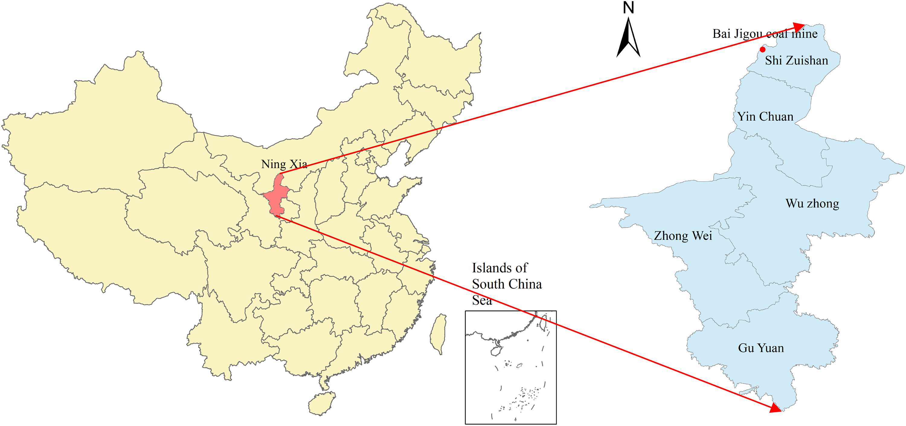
Location of Baijigou Coal Mine.
During the mining process of the 010203 working face, due to the influence of mining pressure and full negative pressure ventilation, the coal pillars around the working face and the gas in the goaf will flow into the working face in large quantities. Therefore, to control the gas, considering the retaining of the gob-side entry in the return air roadway of the 0102402 working face, it should be used as a gas drainage roadway to extract the gas in the 010203 section to reduce the loss of coal pillars in the section. Thus, research on the technology of gob-side entry retention at the bottom of the layered mining of extra-thick coal seams is proposed.
Overview of the working face
The working face is arranged in the sixth stage of the south-wing mining area of Baijigou. The +1665 m return airway is arranged in the mining area, and the No. 2 and No. 3 return air connection lanes are arranged from south to north, where the No. 3 return air connection lane communicates with the 0102402 return air roadway and the +1665 return air roadway. The 0102402 fully mechanized mining face is west of the 0102402 return air lane, east of the 0102402 transport lane, and north of the 0102402 working face design stop position, and the return air lane and transport lane are arranged along the strike. The layout of the working face roadway is shown in Figure 2.
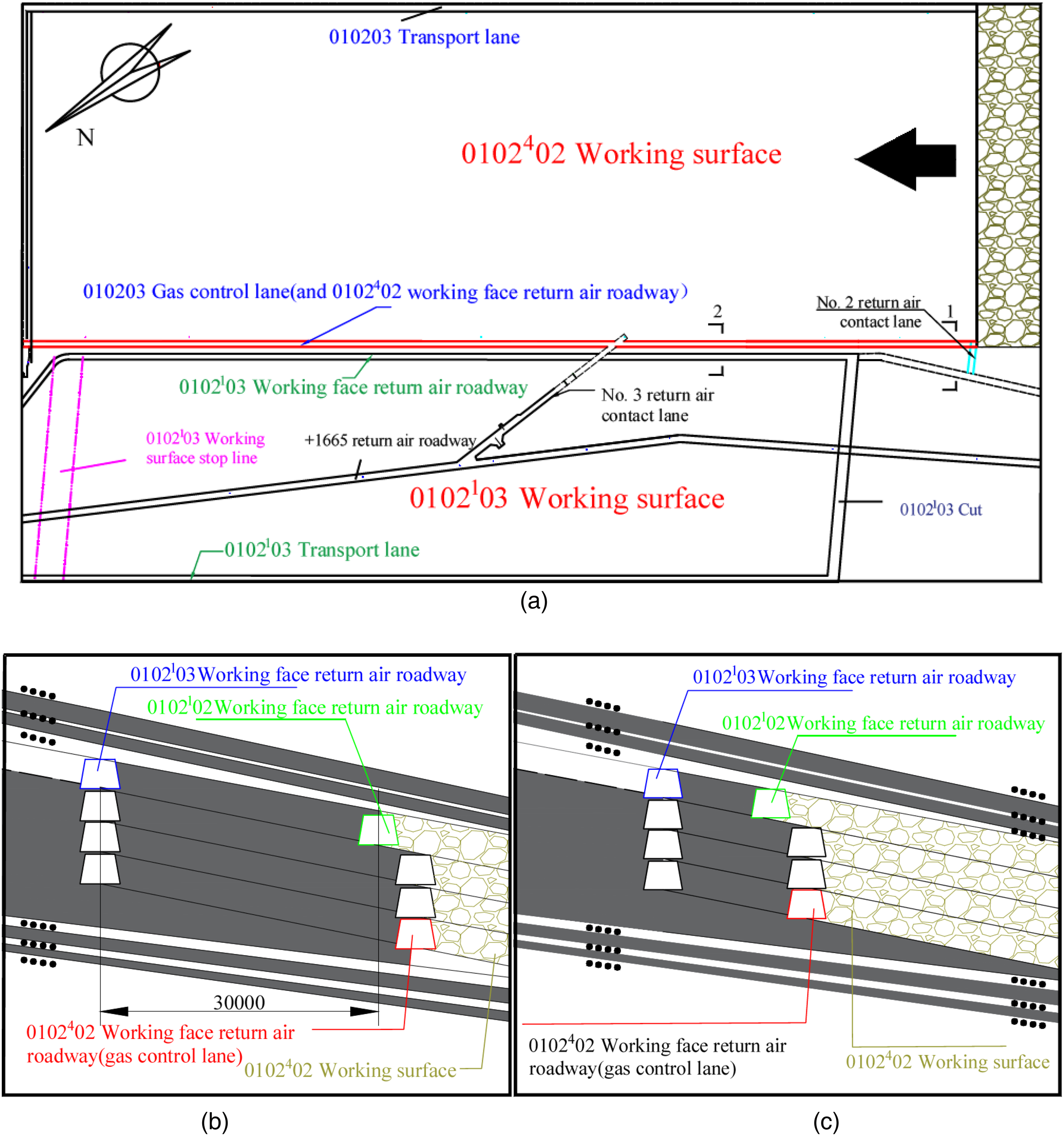
Working face roadway layout: (a) Floor plan, (b) 1-1 sectional view of the roadway location, and (c) 2-2 sectional view of the roadway location.
The 23 coal seams mined in the Baijigou Coal Mine of Rujigou Anthracite Coal Mine are extra-thick coal seams. The direct tops of these workings are 3.0–11.0 m thick, with an average thickness of 6.6 m. The lithology is grey-black thin-bedded siltstone. The thickness of the pseudo top is 0.1–0.4 m, with an average thickness of 0.2 m, and the lithology is relatively soft carbonaceous mudstone. The thickness of the direct bottom is 23.1 m, and the lithology is black thin-layered siltstone. The comprehensive histogram of coal strata is shown in Figure 3.
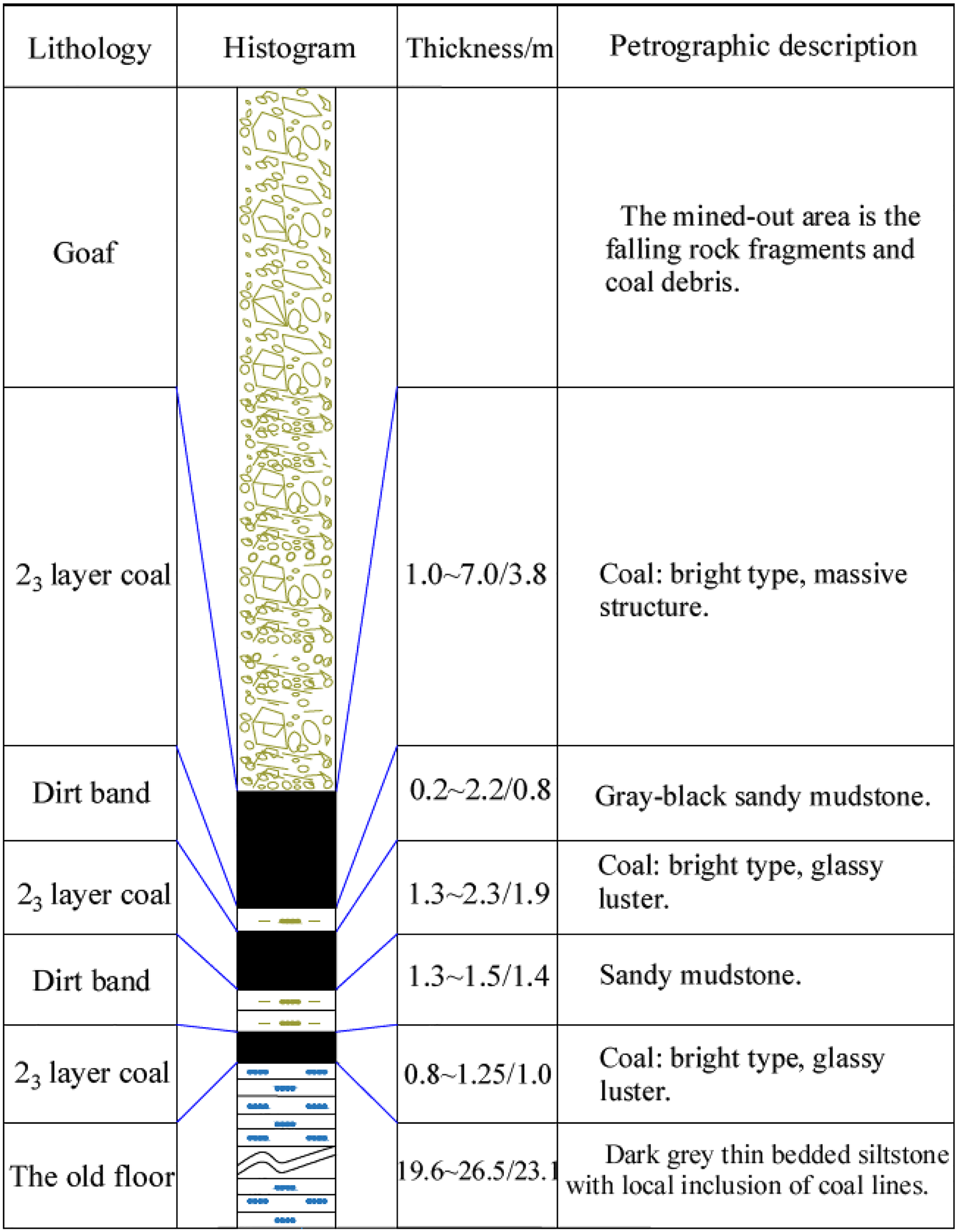
Comprehensive histogram of coal and rock in the working face.
In the Baijigou Coal Mine, relevant research was carried out on the coal pillar retention between the 010203 working face one-layered air return roadway and the 010202 working face four-layered air return roadway. The results show that coal pillars with a size of 8 m should be left between the roadways. However, in actual engineering practice, it is found that there is still significant danger in using 8 m coal pillar supports. Therefore, in the process of retaining the four-layered return air roadway in the 010202 working face, it is necessary to consider the reinforcement and support of the 8 m small coal pillars.
Roadway support and mining status
The roadway of the 0102402 working face is a trapezoidal section, with a net width of 3200 mm at the top and 4628 mm at the bottom; the net height is 3200 mm, the net sectional area is 12.5 m2, and the design length is 1252 m. The original support form of this roadway is a trapezoidal metal bracket to shed support, 3424 mm (beam) × 3452 mm (leg), all of which are No. 11 mining I-beams. The original support section of the roadway is shown in Figure 4.
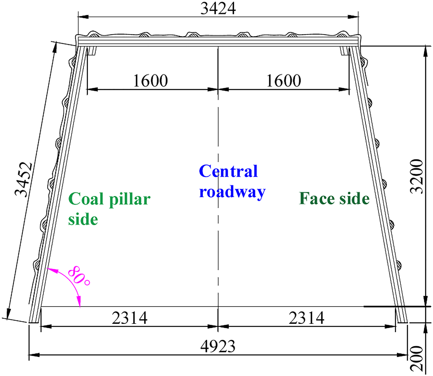
Roadway support sectional view.
The 010202 working face has been mined for several years since layer 1. Through an analysis of the borehole histogram, in the process of three-layer mining, the movement of the overlying strata is found to be in an approximately stable settlement state. Consequently, understanding the mine pressure caused by the mining of the 010202 working face has a certain guiding significance for mining the 010203 working face. Further, it helps evaluate the retention of coal pillars between the mining sections.
West of the 010202 working face is the goaf of the 010201 working face; the gob of the 1411 and 1422 working faces is in the east, but at a certain distance away. To the south is the security coal pillar of the riverbed of the Naligou upper coal formation, and to the north is the security coal pillar of the Baijigou upper coal formation, both of which are unmined areas. The coal seams 21 and 22 on the upper part of the working face are basically unmined, and only the 21, 22 combined seam 1611 working face goaf is covered in the local area.
A section coal pillar with a net width of 30 m is set between the 010202 and 010201 working faces, and a transport roadway is arranged on the side near the coal pillar. During the mining process of the working face, the general law is that the layer 1 pressure is not high, and the layer 2 pressure is severe. As the mining stratification continues to the lower regions, the mining pressure of the working face and mining roadway gradually decreases. Furthermore, the 010202 working face generally experiences the relatively severe pressure of the transport road within a range of about 100 m before and after the connecting road.
Flexible formwork supports
Basic features of flexible formwork support
Through years of scientific research and engineering practice, Professor Xiaoli Wang's team, from Xi’an University of Science and Technology, has successfully developed the flexible formwork concrete gob-side entry retention support technology, referred to as a flexible formwork support. Its technical characteristics are as follows: along with the advancement of the working face, a flexible formwork made of high-strength fiber material is hung between the roadway and the goaf. Soon after, concrete is pumped into the flexible formwork. The formwork is forced to dehydrate and connect to the top, forming a flexible formwork concrete continuous wall. The wall supports the roof, closes the goaf, and retains the roadway to serve the next working face.
This flexible formwork has the characteristics of self-forming, lightweight, easy installation, pre-reservation of measure holes, no need for formwork removal, and convenient construction, as shown in Figure 5. During construction, the water-permeable and impermeable properties of the flexible formwork are used to greatly shorten the concrete setting time. After 3 h of concrete pouring, the strength can reach 0.8 MPa, which forms effective support for the surrounding rock of the roadway. At present, the technology has been successfully applied in more than 70 mine working faces in China; has achieved good technical, economic, and social benefits; and has broad application prospects.
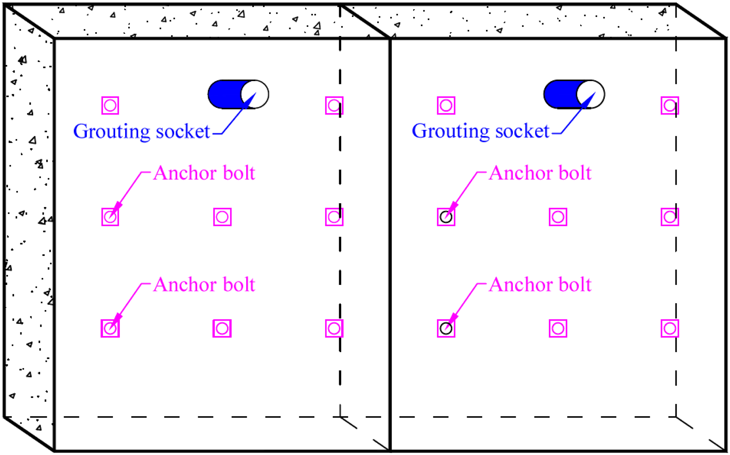
Flexible model and sample.
Flexible formwork support construction technology and process
After years of research and engineering practice summary by Professor Xiaoli Wang's team, a complete construction specification system has been formed for flexible formwork support from technology to complete sets of equipment. The basic construction technology (a) and process (b) of gob-side entry retention with flexible formwork concrete, as shown in Figure 6, can be adjusted according to different working conditions.
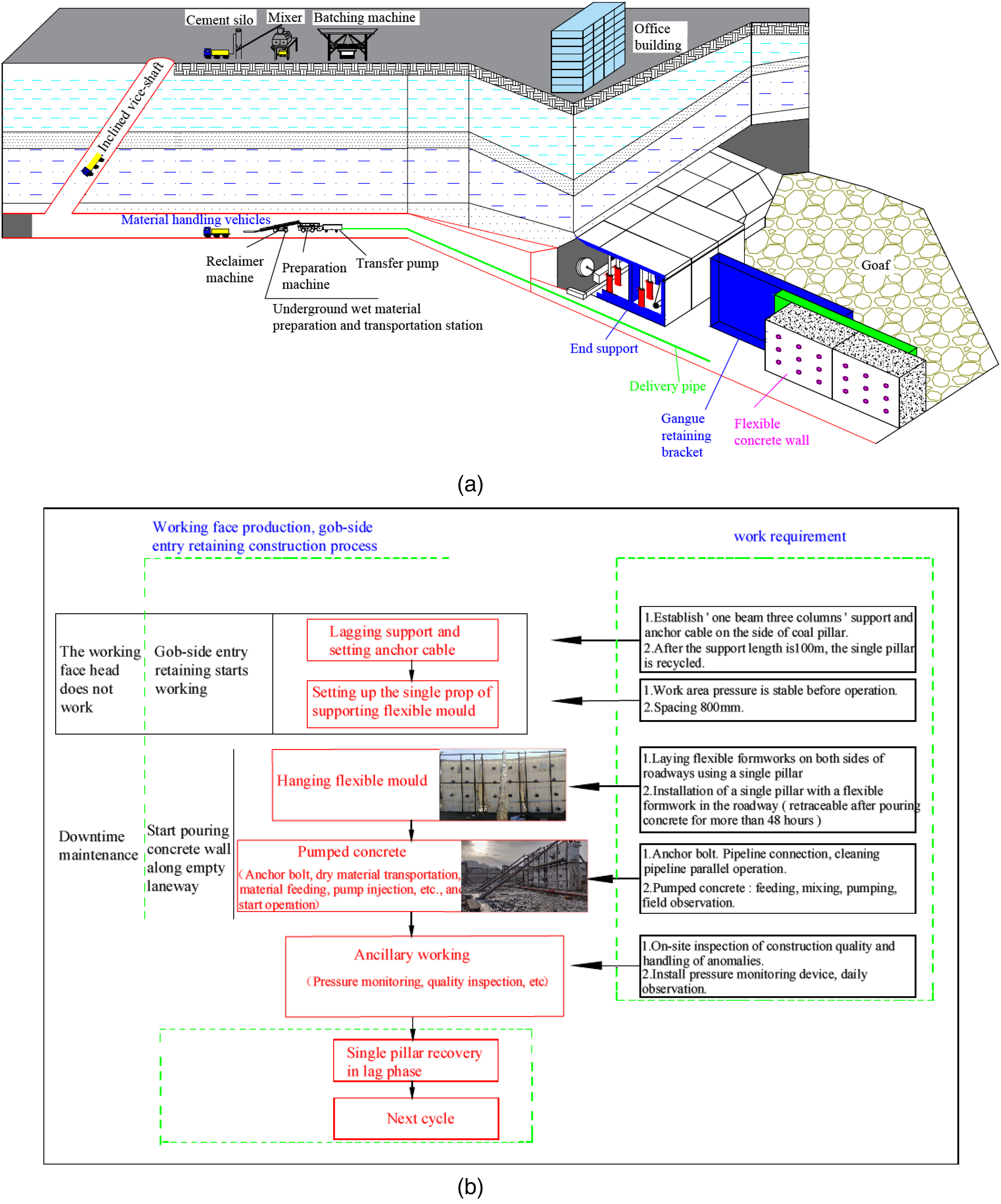
Construction technology and flow of gob-side entry retention: (a) construction technology and (b) construction process.
Calculation of support load for gob-side entry retention with flexible formwork
Common models for load calculation
Method of separating rock blocks (He, 2000)
This method is based on the idea that the weight of the separated rock blocks in a certain range above the backfill body of the gob-side entry retention constitutes the load of the backfill body beside the roadway. In these calculations, the roadside backfill is simplified such that it is constructed at the center of the mass of the rock block on the roof. It is also assumed that the rock blocks on the roadside backfill only provide static loading, and are not affected by forces on the top and both sides of the rock block. The backfill body beside the roadway is located between the high-pressure area on the side of the roadway retention coal side and the gangue compaction area in the goaf area, which is a pressure reduction area. The rock block provides a free surface on one side of the goaf, which is layered. Separation may occur at a certain height, causing the rock block to break at a certain angle along the road retention coal gang, and enter a completely free state, providing loading for the backfill body beside the roadway. The calculation model of the support load of the roadside filling body using the “separated rock method” is shown in Figure 7.

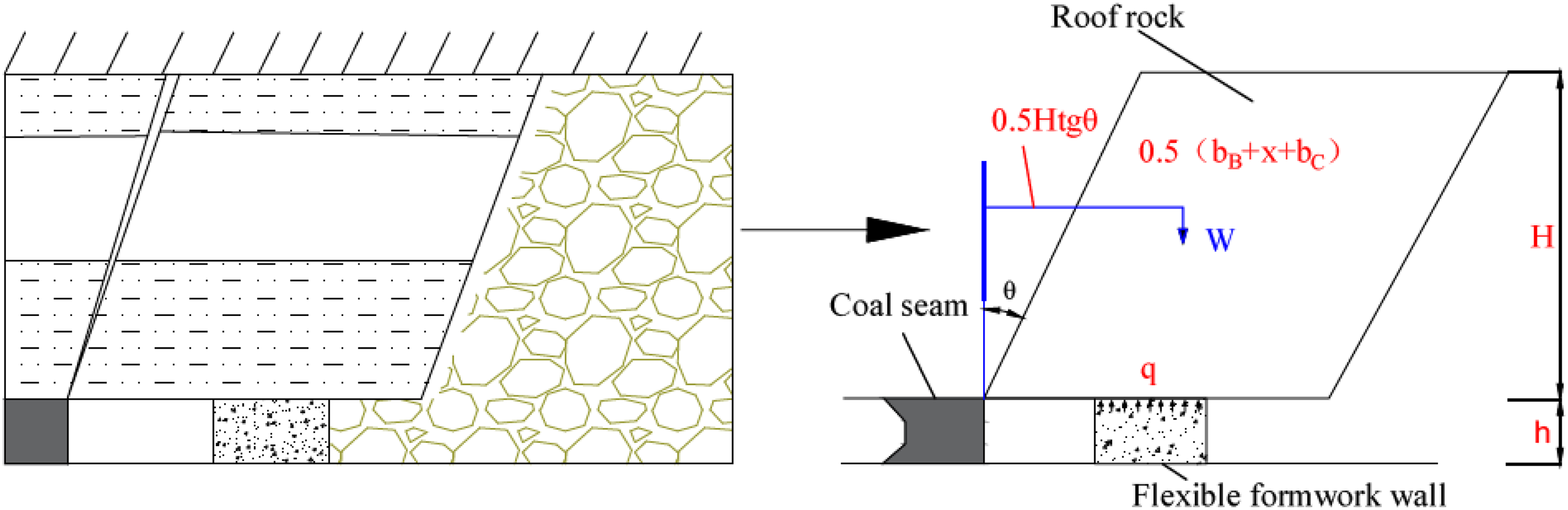
“Separated rock method” load calculation model for roadside backfill.
where q represents the support load of the filling body (t/m); bB represents the distance from the edge of one side of the gob-side entry retention of the flexible formwork wall to the coal wall (m); x represents the width of the flexible wall (m); bC represents the overhang distance outside the flexible formwork wall (m); γs represents the average bulk density of the separated rock blocks (kN/m3); h represents the coal mining height (m); θ represents the direct top caving angle (°); α represents the dip angle of the coal seam (°); and H represents the height of the caving zone, which is generally four times the mining height (m).
The abovementioned data are valued according to the specific conditions of gob-side entry retention in coal mines, and can be substituted into equation (1) to obtain the support load of the roadside backfill with a width of x. Considering the influence of dynamic pressure caused by the fracture of the triangular suspension plate of the working face, the dynamic pressure coefficient is generally taken as 2–4. Then, during gob-side entry retention, the maximum load acting on the backfill body beside the flexible formwork concrete roadway is represented in equation (2).

Top-cut method (Zhu, 1996):
The concept underlying this method is that, at some point on the leading working face, a small asymmetrical subsidence of the roof exists, the closer the working face to this subsidence, the greater the subsidence, resulting in the maximum deflection of the lower rock formation. After the working face is pushed out, it is equivalent to removing an effective support for the roof, and the roof sinks sharply (Gao et al., 2017; Zhu et al., 2019). Under the action of the roadside support resistance, the overhanging roof sinks quickly, reaching the limit moment at the side edge of the gob side of the roadside support body and subsequently breaking. After the gangue filling the goaf is compacted to a certain extent, a relatively stable pressure arch is formed above the roadway, and roof movement is also restricted. The model is shown in Figure 8.
Calculation model of backfill support load using the top-cut method.
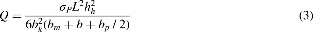
where Q represents the support load of the filling body (t/m); σp represents the tensile strength of the top plate (MPa); L represents the length of the fractured rock, whose value is equal to the period to press the step distance; bm represents the distance from the fracture line to the coal gang (m); b represents the width of gob-side entry retention; bp represents the width of the flexible wall (m); bk represents the overhang distance (m); and hh represents the breaking height of the roof.
The abovementioned values can be substituted into equation (3) to obtain the support load Q on the backfill body beside the flexible form concrete roadway. The bearing capacity of the flexible form concrete infill is much greater than the maximum load acting on it. When the theoretically calculated safety factor is greater than 2, it can be considered that the design of the flexible formwork concrete filling body meets the support safety requirements.
Although there is a difference between the simplified environment set by the two aforementioned calculation theories and the actual environment, the calculation results are biased toward safety. Further, their calculation processes are simple and convenient. Therefore, they are widely used to calculate the support load beside the gob retention roadway.
Calculation model of gob-side entry retention loads in Baijigou
The Baijigou Coal Mine is part of the layered gob-side entry retention at the bottom of the extra-thick coal seam layered mining. Therefore, the widely used gob-side entry retention load calculation method is no longer applicable. When Baijigou Coal Mine conducts 010202 working face four-layer mining, its gob-side entry retention roof is finally in the “given load” working state. The model is shown in Figure 9.
Calculation model for gob-side entry retention loads in Baijigou Coal Mine.
In Figure 9, I is the “regenerated” rock formation above the roadway, and its height is the height of the re-compacted rock formation in the middle layer caving zone. This part of the rock acts on the gob-side entry retention support in the shape of an inverted ladder. II is the lower rock formation in the fracture zone after middle layer mining. With the bottom-layer mining, the caving height increases, this part of the rock layer loses mutual connection, and its own weight acts on the retention bracket through I. Then, the load P of the retention bracket, that is, the load P of the flexible formwork wall, can be found using equation (4).

where P1 represents the bulk density of the rock formation in part I; P2 represents the bulk density of the rock formation in part II.


According to the condition of 23 coal in the Baijigou Coal Mine, take V=22 kN/m3, B=3.4 m, EM=9.6 m, K’P=1.2, T=75°, and h=3.2 m. Substitute these values into equations (7) to (9) to obtain the following: Hm=12.77–17.17 m, take 17.17; H’=17.17 m; H=14.3 m; and B’=11.1 m. Finally, equations (5) to (6) can be used to obtain P1=0.45 MPa; P2=0.32 MPa; and P=0.77 MPa. That is, the stable support pressure of the wall beside the road is 0.77 MPa. Considering the influence of multiple mining iterations, the maximum mining support pressure is set to be four times the stable pressure, at 3.08 MPa.
For safety reasons, the concrete design strength is C30 and the thickness of the flexible concrete is taken as 1 m. This is based on the calculation results and the fact that there is no widely accepted practical experience for gob-side entry retention in layered mining. After the final construction, optimization will be carried out according to the observed mine pressure.
Gob-side entry retention support technology
Reinforcement and support of small coal pillars
Supporting principles
Due to the characteristics of underground engineering, the rupture of the surrounding rock of the roadway does not imply that the surrounding rock is unstable. The rupture of the surrounding rock only means that the rock mass is in the post-peak weakening or residual strength stage, but it still has a certain bearing capacity (Chen et al., 2018; Ma et al., 2018). The main function of the roadway support is to provide radial restraint to the surrounding rock. This compensates for the three-way stress state lost in the surrounding rock as a result of excavation and allows the friction between the fractured rock blocks to maintain their radial continuity. The support can hinder the relative dislocation and sliding between rock masses, thereby effectively slowing down the volume expansion and strength attenuation of the rock mass after the peak. Further, it can generate and maintain a certain confining pressure in the rupture zone of the surrounding rock of the roadway and maximize the self-supporting capacity of the surrounding rock, making it a good bearing structure. The greater the support resistance (confining pressure), the greater the residual strength of the rock mass and the greater the bearing capacity of the broken weak structural surrounding rock (Yan et al., 2019).
When small coal pillars are left for gob-side tunnels, the mining roadway is arranged in the internal stress field with laterally distributed bearing pressure. Under the action of supporting pressure, the coal pillar on the side of the goaf is damaged during the mining process of the adjacent working face. In addition, the coal body loses its integrity, producing a large number of longitudinal cracks in its interior and forming a plate-like structure. Long-term practical experience also shows that, under the condition of a large mining height, a small coal pillar gob-side roadway is usually accompanied by a large amount of deformation during the mining process of the working face, which makes the roadway require a certain amount of expansion and repair work. Therefore, the principle of supporting the small coal pillar along the gob side of the mining roadway involves increasing the residual strength of the small coal pillar through active support to improve its bearing capacity. More importantly, it is imperative to control the increase in the deformation of the roadway side caused by the continuous shear expansion deformation of the small coal pillar under the action of the bearing pressure. For the roadway on the solid coal side, high-strength support should be implemented to improve its bearing capacity toward the mine pressure transmitted by the falling gangue and the upper rock structure in the upper goaf area.
Reinforcement and support of small coal pillars
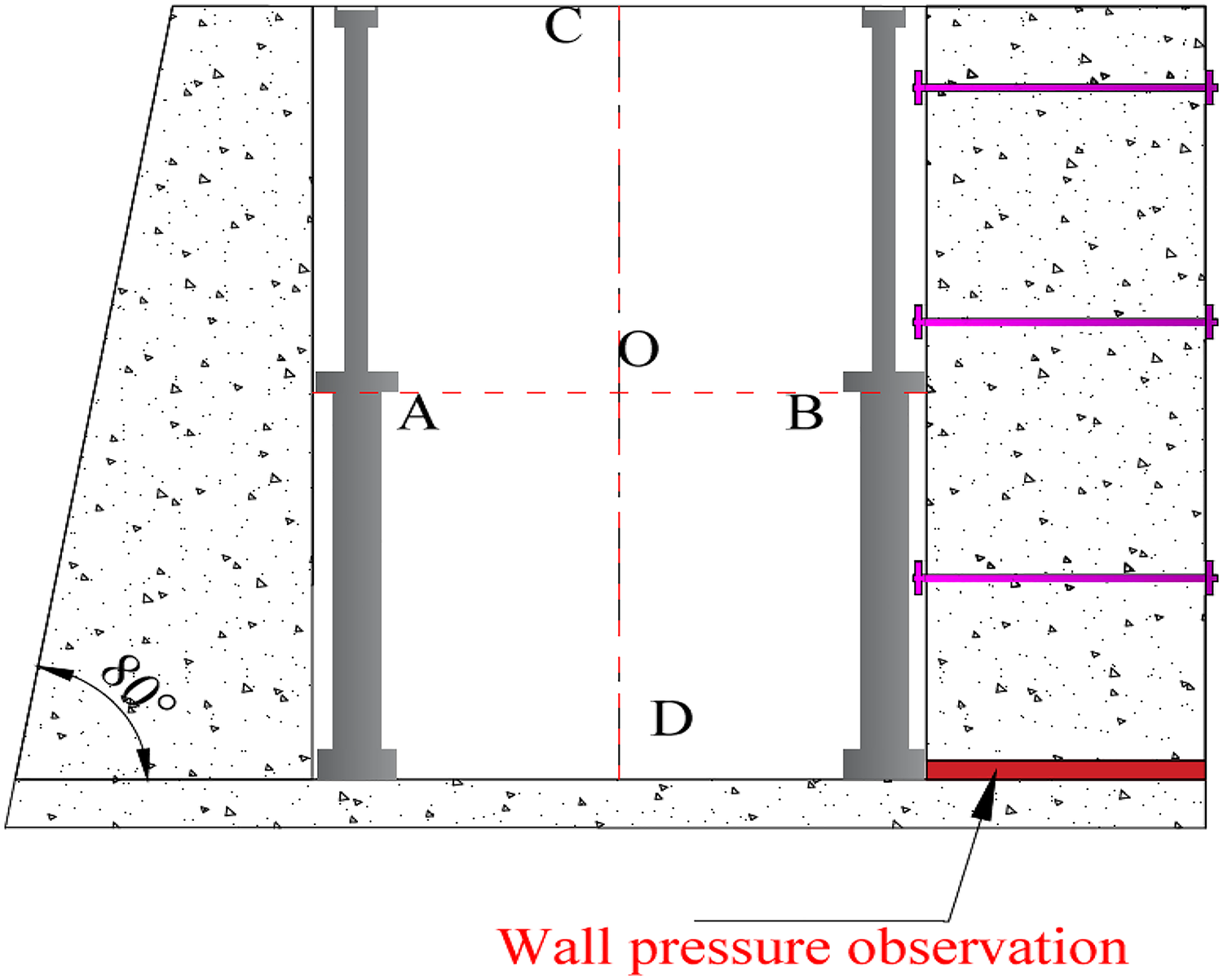
Through the comprehensive analysis of the actual working conditions on-site, this study proposes—for the first time, to the best of our knowledge—the strengthening of small coal pillars by the combined support of a flexible formwork concrete wall and anchor cable. The specific parameters are as follows: the flexible formwork wall is a trapezoidal wall with an upper width of 500 mm and a lower width of 1000 mm, and the strength of C30. One φ21.96×4500 mm anchor cable is set 500 mm away from the top plate, one φ21.96×5000 mm anchor cable is set at 1500 mm and 2500 mm from the top plate, and the anchor cable row spacing is 1000 mm. Three sections of MSZ2370 resin anchoring agent are used, and the anchor cables are arranged in double trays. That is, the anchor cables are first laid on the coal wall and a pre-tightening force is applied. Subsequently, the leakage part of the anchor cables is passed through the flexible formwork wall. The second layer of supporting plates is installed to form the flexible formwork concrete wall + anchor cable joint support, as shown in Figure 10.
Cross-sectional view of the small coal pillar reinforcement support.
Support design of the flexible formwork double-wall roadway
After gob-side entry retention, the flexible formwork concrete continuous wall will experience multiple dynamic pressure effects. However, there is a lack of research on layered gob-side entry retention at the bottom of layered mining. Therefore, to ensure that the roadway meets the safety requirements for the use of gas drainage roadways under the influence of multiple mining pressures, the design strength of concrete is tentatively set at C30, and the thickness of flexible formwork concrete is taken as 1 m. After the actual construction, optimization should be carried out according to the observation of the mine pressure of the wall.
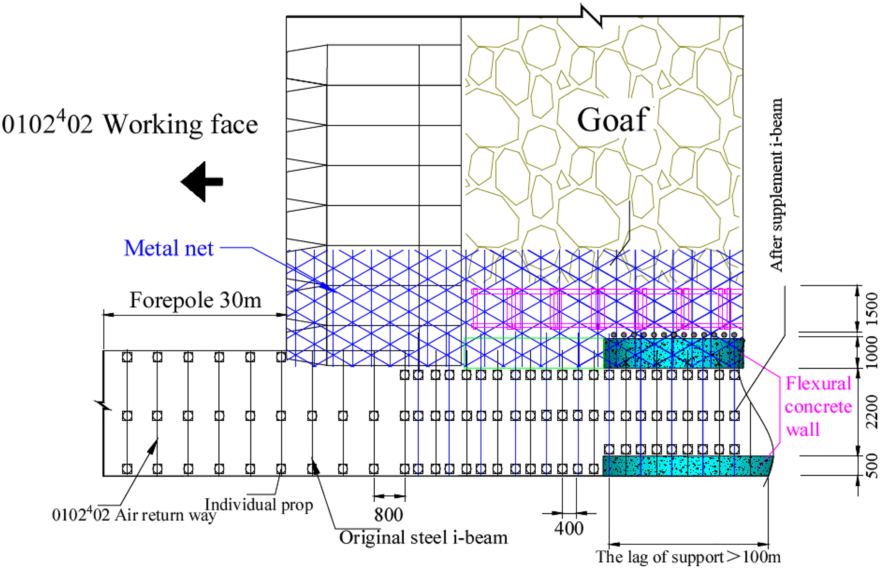
To ensure adequate support, gob-side entry retention roadway support is combined with small coal pillar reinforcement. A double-flexible formwork concrete wall support technology for layered gob-side entry retention at the bottom of layered mining of extra-thick coal seams is proposed. The specific support plan is as follows: the designed roadway has a net width of 2200 mm, a height of 3200 mm, and a net section of 7.04 m2. The lower side of the return air roadway (mining side) is supported by flexible formwork concrete, the thickness of the flexible formwork concrete wall is 1000mm, the design strength is C30, and it is poured on the side of the goaf. The upper part (coal wall side) is supported by a flexible formwork concrete trapezoidal wall, the upper width of the flexible formwork concrete wall is 500 mm, the bottom width is 1000 mm, the design strength is C30, and it is poured close to the coal wall. During gob-side entry retention, the top of the I-beam supported in the original roadway is retained, and a single pillar is installed near the mining side to support the I-beam. Further, at the top of the two walls, another No. 11 I-beam (length 4200 mm, row spacing 0.8 m) is supported by the walls. During mining, a roof net (width 5 m) should be laid along the working face inclination (toward the direction of the machine head), at the place where the precast wall is under the return air roadway, to block the gangue and protect the roof. The metal mesh is diamond-shaped, woven with No. 8 lead wire, with a mesh size of 50 mm × 50 mm; it is laid in two layers, as shown in Figure 11.
Supporting section diagram of gob-side entry retention.
Temporary reinforcement support
When gob-side entry retention is implemented, the return air roadway should be strengthened 30 m ahead of time, and a single pillar should be set up in the middle of the roadway, for support. The lag working face is supported by the single unit of the pouring flexible formwork wall, and the lag support distance is 100 m. Temporary reinforcement support is shown in Figure 12.
Temporary reinforcement support design.
Activity law of surrounding rock in gob-side entry retention at the bottom of the extra-thick coal seam
Some coal mines have carried out industrial tests on gob-side entry retention in the upper layers of thick coal seam mining. However, the gob-side entry retention layer under the layered mining of thick coal seams has not been applied widely because its support technology is not applicable and road retention is more difficult. Therefore, there is a lack of in-depth research on the mine pressure law and supporting technology of gob-side entry retention in the middle and lower layers of thick coal seams globally. The Baijigou Coal Mine has successfully applied flexible formwork concrete gob-side entry retention in the 4th layer of the extra-thick coal seam. Further, the law of occurrence of mine pressure has been fully understood, in addition to reasonable support forms and parameters of gob-side entry retention at the bottom of thick coal seams. This has significant reference potential for middle- and lower-layer gob retention in thick coal seams.
Industrial applications
It is crucial to fully understand the deformation law and the roof pressure law of the roadway to provide a basis for the subsequent optimization of roadway support. The monitoring of gob-side entry retention in the return air entry of the 0102402 working face is shown in Figure 13. The industrial application effect of part of the roadway retention is shown in Figure 14(a and b).
Surrounding rock convergence deformation monitoring: This mainly includes the subsidence amount of the top plate, the subsidence amount of the bottom drum, and the amount of movement of the flexible formwork walls on both sides, with a total of eight measuring points. Surrounding rock load monitoring: That is, roof pressure monitoring, where a total of four measuring points are arranged.
Roadway deformation monitoring.
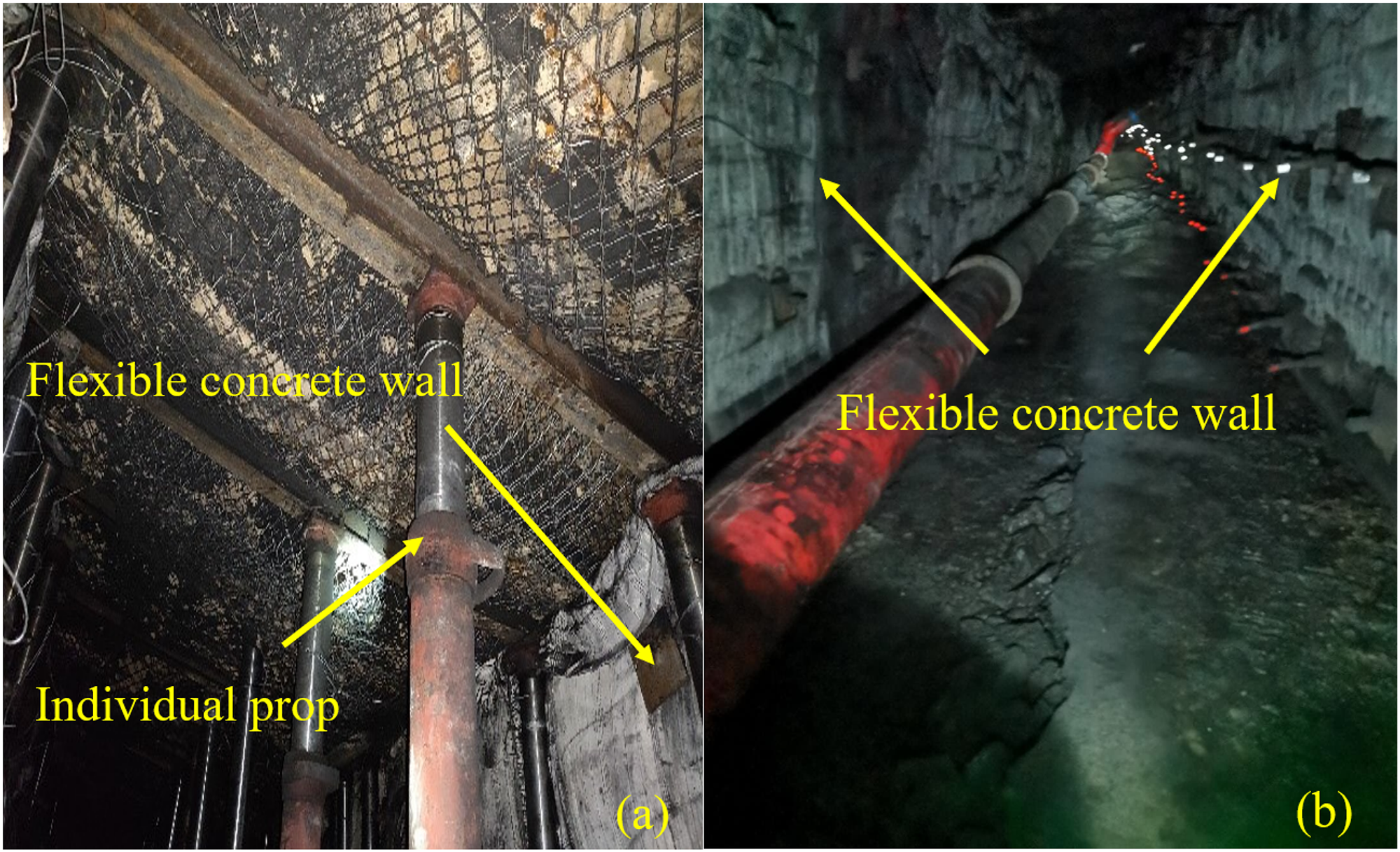
Industrial application effect: (a) Individual prop before retraction and (b) individual prop after retraction.
Deformation characteristics of the roadway stage
By observing the mine pressure of the roadway and analyzing the practical situation of the roadway, the roadway conditions can be divided into the following four stages. Stage 1: From gob-side entry retention to the 0102103 working face cutout, the roadway is about 80 m long and does not enter the 0102103 working face. At this stage, the coal pillar is wider, and there is no goaf above the roadway in this section of the 010202 working face. Stage 2: It is 80 m from the incision of the 0102103 working face to the direction of the roadway, the central size of the coal pillar is 9 m, and the 010202 working face has no goaf above this section of the roadway. In comparison to the 010202 working face, the roadways of the first and second stages are all located below the solid coal. Stage 3: The length of the roadway is about 100 m from the 160-m position from the gob-side entry retention to the fracture of the No. 3 return air connection lane. Stage 4: The remaining part of the roadway in the 0102402 working face that is about 400 m. The position plane of each stage of gob-side entry retention is shown in Figure 15.
Stage 1: Monitoring and analysis
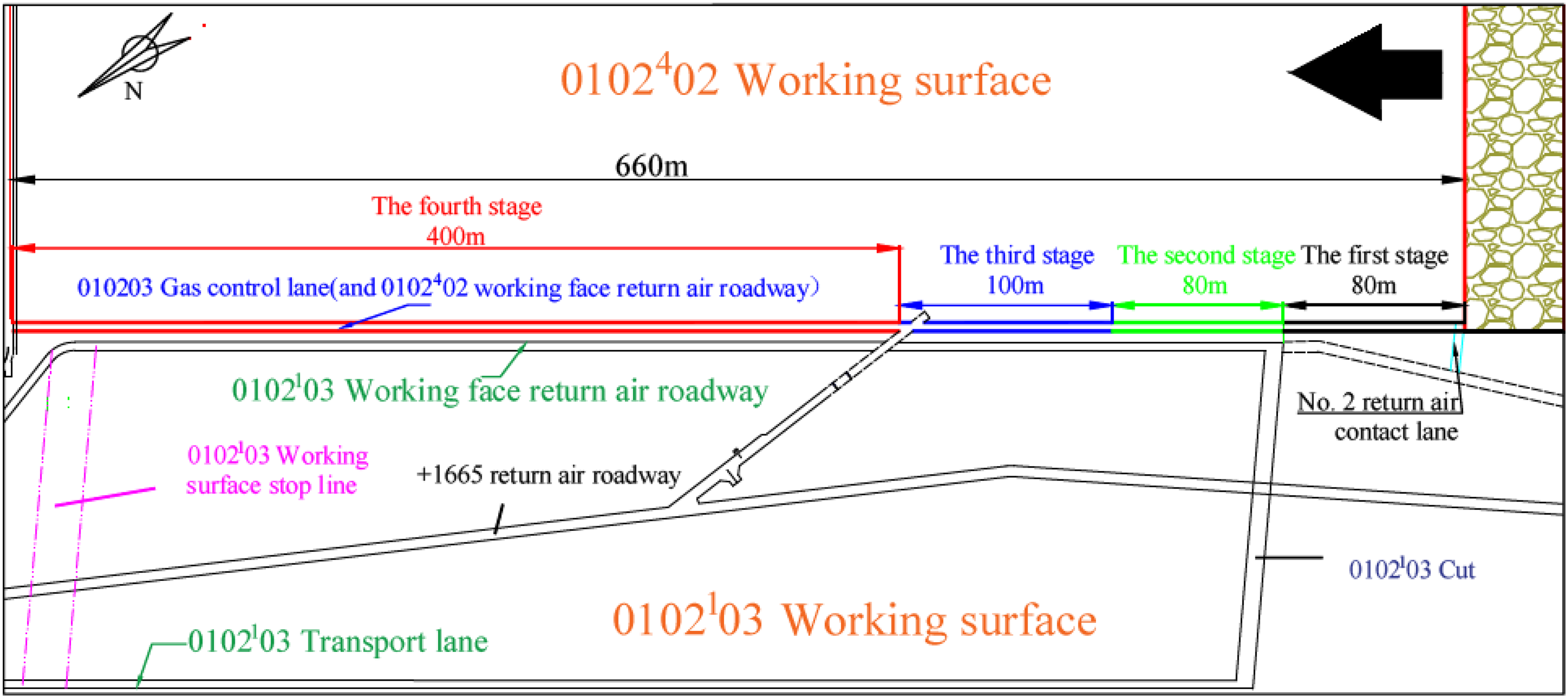
Diagram of the four stages.
The No. 1 and No. 2 surrounding rock convergence deformation measurement points are located at 30 m and 80 m of the gob-side entry retention, respectively, and the 1# roof pressure measurement point is located at the 60-m position of the gob-side entry retention. It can be seen from the monitoring data and on-site conditions that the deformation variables of the first 60 m of the roadway retention are basically stable. After withdrawing the single column in the middle row of the lag working face, the displacement of the top and bottom plates changes. The approaching amount remains within 250 mm after stabilization, and the approaching amount on both sides is small. The roof pressure is stable, at about 6.0 MPa, that is, the overall roadway retention effect is better in the first stage. The displacement monitoring analysis is shown in Figure 16(a) and (b). The roof pressure monitoring analysis is shown in Figure 17(a). The scene after gob-side entry retention is shown in Figure 18(a).
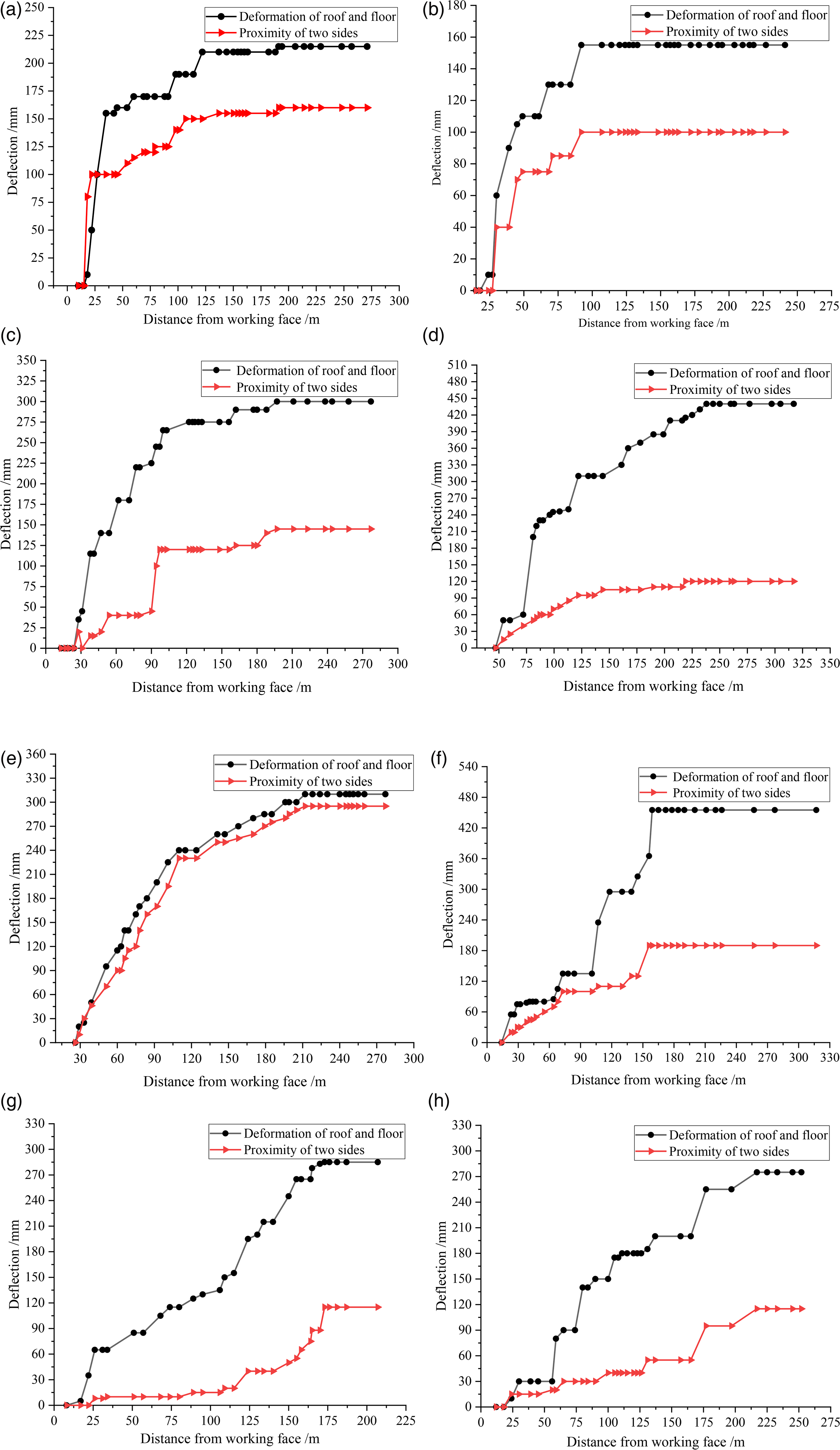
Surrounding rock convergence data diagram: (a) 1# measuring point, (b) 2# measuring point, (c) 3# measuring point, (d) 4# measuring point, (e) 5# measuring point, (f) 6# measuring point, (g) 7# measuring point, and (h) 8# measuring point.
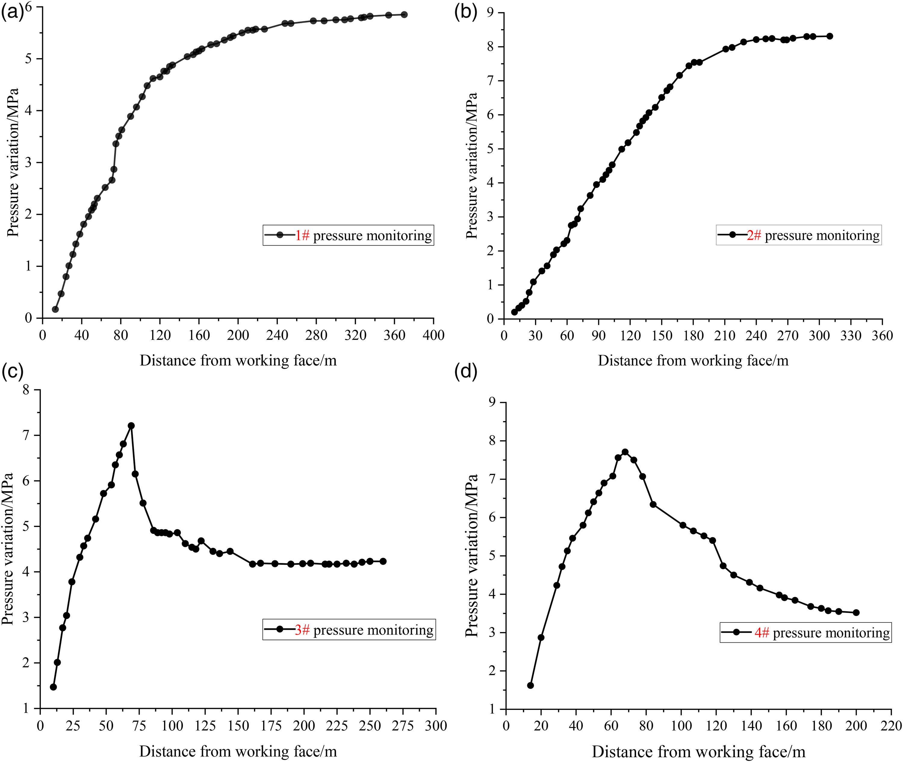
Roof pressure data chart: (a) 1 # pressure measuring point, (b) 2 # pressure measuring point, (c) 3 # pressure measuring point, and (d) 4 # pressure measuring point.
Application diagram of each stage: (a) The first stage, (b) the second stage, (c) the third stage, and (d) the fourth stage.
The indication that the deformation of the surrounding rock is stable is that the subsidence rate of the roof is reduced to 0.5–1.0 mm/d. At this time, the impact of mining has been reduced, and the distribution law of lagging support pressure in the working face can be analyzed accordingly. The first stage of the roadway is located in the 23 coal seam, the upper part 21 and 22 coal is the unmined area of the coal seam, and the width of the adjacent side coal pillar is large. According to the observation data, after lagging the working face by 100 m–120 m, the deformation speed of the surrounding rock of the roadway tends to stabilize. It can be concluded that this section of roadway has been stabilized under the influence of the primary mining pressure of the working face. The support strength of this section of the roadway meets the requirements of gob-side entry retention. In the later stage, when mining the 0102103 working face, the observation of the roadway in this section should be strengthened further. If necessary, single pillars or wooden point pillars should be used to support the middle of the roadway to prevent large deformations at the weak points of the roadway support structure.
Stage 2: Monitoring and analysis
The No. 3 surrounding rock convergence deformation measurement point is located at 130 m from the gob-side entry retention. The No. 4 surrounding rock convergence deformation measurement point is located at the 160 m position of the roadway. The 2# roof pressure measuring point is located 150 m away from the roadway. It can be seen from the monitoring data and on-site roadway retention that the roadway deformation is larger than that in the first stage. The maximum movement of the roof and floor is close to 480 mm (the No. 4 surrounding rock convergence measurement point), as shown in Figure 16(c) and (d). This primarily manifests as the amount of bottom heave in the roadway increasing, and the amount of movement of the two sides does not change much. The 2# roof pressure measuring point observes that the roof pressure of the roadway reaches 8.5 MPa after the mining dynamic pressure stabilizes, as shown in Figure 17(b).
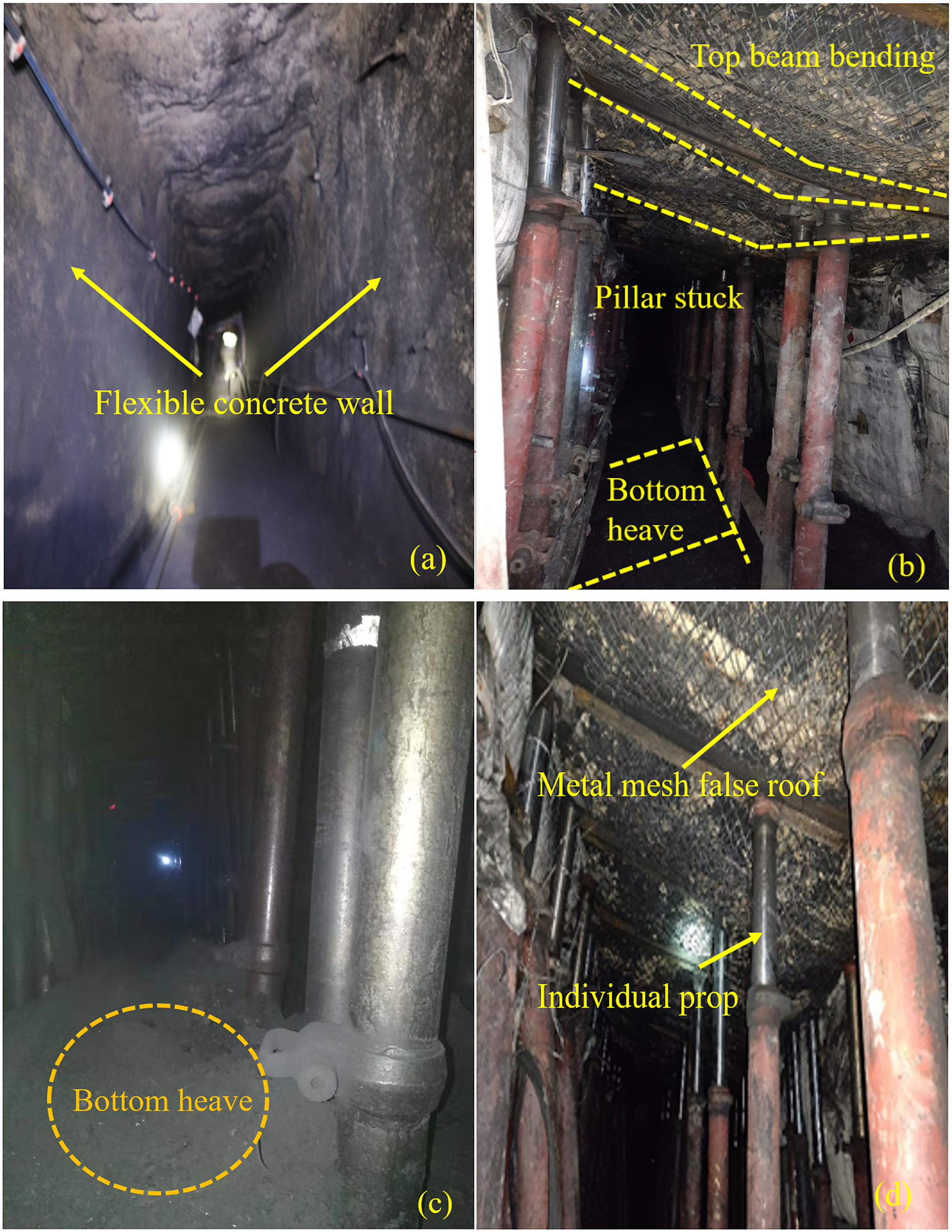
At this stage, the upper part of the roadway is still in the unmined area of 21 and 22 coal. However, due to the impact of the opening of the cutting eye and the narrowing of the coal column in the adjacent working face, the dynamic pressure of mining is more serious after 30m–50m of the lagging working face. This leads to the bending of the roof steel beam of the roadway and the intensification of the bottom heave, as shown in Figure 18(b). Furthermore, severe plastic damage to the coal pillars in the return air roadway of the excavated roadway 0102103 occurs, alongside the intensified deformation of the roadway roof and floor. In addition, the scaffolding in the roadway also deforms.
Stage 3: Monitoring and analysis
The No. 5 surrounding rock convergence deformation measurement point is located at the position of 210 m from the gob-side entry retention. The No. 6 surrounding rock convergence deformation measurement point is located at the 240 m position of the roadway. The 3# roof pressure measuring point is located 190m away from the roadway. It can be seen from the monitoring data and on-site roadway retention, as shown in Figure 18(c), that the deformation of the roadway still manifests as a large amount of movement of the roof and floor: this movement amount reaches 480 mm at the 240 m point of the roadway. This primarily manifests as a large amount of floor heave in the roadway; the maximum displacement of the walls on both sides is close to 300 mm at 210 m of the roadway, as shown in Figure 16(e) and (f). The observation of the 3# roof pressure measuring point shows that the mining dynamic pressure of the working face at this stage exhibits obvious regularity, and the maximum pressure does not exceed 7.5 MPa, as shown in Figure 17(c).
At this stage, the upper part of the roadway is below the goaf of 21 coal and 22 coal. The dynamic pressure of the lagging working face exhibits obvious regularity. From the start of pressure monitoring at 3# until 70 m into the lagging workface, the lagging pressure in the roadway exhibits a linear increase in relation to the distance the workface is advanced. The stress reaches a maximum value of approximately 7.5 MPa at 70 m of the lagging workface. Subsequently, with the advancement of the working face, the roadway at the rear section of the lag working face is in the stress reduction zone until it is stable, at about 3–5 MPa. This stage is in accordance with the distribution law of lag bearing pressure in the mining face.
Stage 4: Monitoring and analysis
The No. 7 surrounding rock convergence deformation measurement point is located at the position of 290 m from the gob-side entry retention. The No. 8 surrounding rock convergence deformation measurement point is located at the 340 m position of the roadway. The 4# roof pressure measuring point is located 280 m away from the roadway. Starting from the incision of the No. 3 return air connection roadway, the roadway pressure of gob-side roadway retention is significantly reduced. It can be seen from the monitoring data and on-site roadway retention, as shown in Figure 18(d), that the deformation of the roof and floor is reduced. Further, the roof enclosure on the side of the goaf is better, the deformation of the roof steel beam is small, and the overall effect of roadway retention is good. Surrounding rock convergence monitoring is shown in Figure 16(g) and (f). The observation results of the 4# and 3# top plate pressure measuring points are similar, and the maximum pressure does not exceed 8 MPa, as shown in Figure 17(d).
As the working face continues to move forward, the dynamic pressure of the lagging working face of the roadway remains basically stable. Further, with the gradual familiarization and improvement of the construction process by the operators, as well as the improvement and optimization of the roadway problems in the previous stages, the overall gob-side entry retention effect is good.
Analysis of the dynamic pressure law of the roadway at various stages
Analysis of the four-stage mine pressure monitoring data shows that the entire process of the collapse of the surrounding rock on the stratified mining face to stability is completed within the range of 60–200 m behind the face. In the first stage, the peak of roadway deformation velocity is located in the range of 20–50 m behind the working face, and the stable zone is located at 100–120 m behind the working face. In the second stage, the peak deformation velocity of the roadway is located in the range of 40–60 m behind the working face, and the stable area is located at 180–200 m behind the working face. In the third stage, the peak of the roadway deformation velocity is located at 50–90 m behind the working face, and the stable zone is located at 160–180 m behind the working face. In the fourth stage, the peak deformation velocity of the roadway is located in the range of 40–70 m behind the working face, while the stable zone is located 150–180 m behind the working face. From this information, it is inferred that the different mine pressure manifestation laws in these stages may be caused by different overlying rock conditions. The 010202 working face is located below the in-situ coal body from the start of gob-side entry retention to 160 m away from the entry retention. Although three layers are mined, the large rock-beam hinged structure formed by the mining of the working face still exists, and it supports part of the overburden load. Due to the existence of the rock-beam hinged structure, the roadway is located in an area of increased stress formed by the mining working face, and the stress peak is located on the in-situ coal pillar coal body. Combined with the appearance law of the mine pressure in the middle and lower layers of the layered mining of thick coal seams, most of the load of the roadway is the superimposed dead weight of the rock blocks in the caving zone of the upper-layer goaf. Simultaneously, with the mining of the working face, the stable load is transmitted through the downward rotation of the hinged rock beam. As a result, there is a long, continuous, and stable pressure increase in this section of the retention roadway, but the overall pressure exhibits a certain periodic regularity.
At 160–260 m of gob-side entry retention, the 010202 working face is below the gob of the overlying coal seam. Affected by the mining of the overlying coal seam working face and the 3-layer mining on this working face, the rock formation structure formed is basically stable. The law of mining pressure in the middle and lower layers of the layered mining of thick coal seams shows that the load borne by the 4-layer roadway of the 010202 working face is the self-weight stress of the caving zone rock formation caused by the upper working face mining. However, the overlying strata structure will not be affected by the mining in this working face. As a result, the pressure in this section of the roadway has increased significantly, and the roadway pressure and deformation are generally close to those of the first and second roadways.
Based on the abovementioned analysis, it can be seen that the mine pressure law of the Baijigou Coal Mine bottom layered gob-side entry retention is obvious, exhibiting a changing trend of “supercharged – peak value – voltage regulation”. Therefore, it is necessary to strengthen the monitoring of the pressure characteristics of each stage to ensure support strength, so as to ensure the effectiveness of gob-side entry retention.
Deformation mechanism and stability analysis
The roadway, after retention, is disturbed by the excavation of the working face and the roadway adjacent to the small coal pillar, which causes the stress state of the surrounding rock to change again. Therefore, the roadway roof and coal pillar coal body are gradually damaged under the action of secondary stress, which eventually leads to the deformation of the roadway through dynamic pressure. By analyzing the deformation characteristics of the roadway and the dynamic pressure law, the three mechanical stages of roadway deformation can be summarized.
Mechanics stage 1: Roof pressure δz< supporting strength in the middle of the roadway Nmz<< roadway wall supporting strength Nwz Mechanics stage 2: Supporting strength in the middle of the roadway Nmz< roof pressure δz<< roadway wall supporting strength Nwz
For 0102402, in the initial stages of roadway retention at the working face, owing to the influence of the dynamic pressure of the working face, the pressure on the roof of the roadway gradually increases, and the roof pressure acts on the supporting structure in the roadway. At this stage, the roof pressure is not large, the roof of the roadway is only deformed slightly, and the support structure in the roadway is stable and effective. Mechanics stage 1 is shown in Figure 19(a).
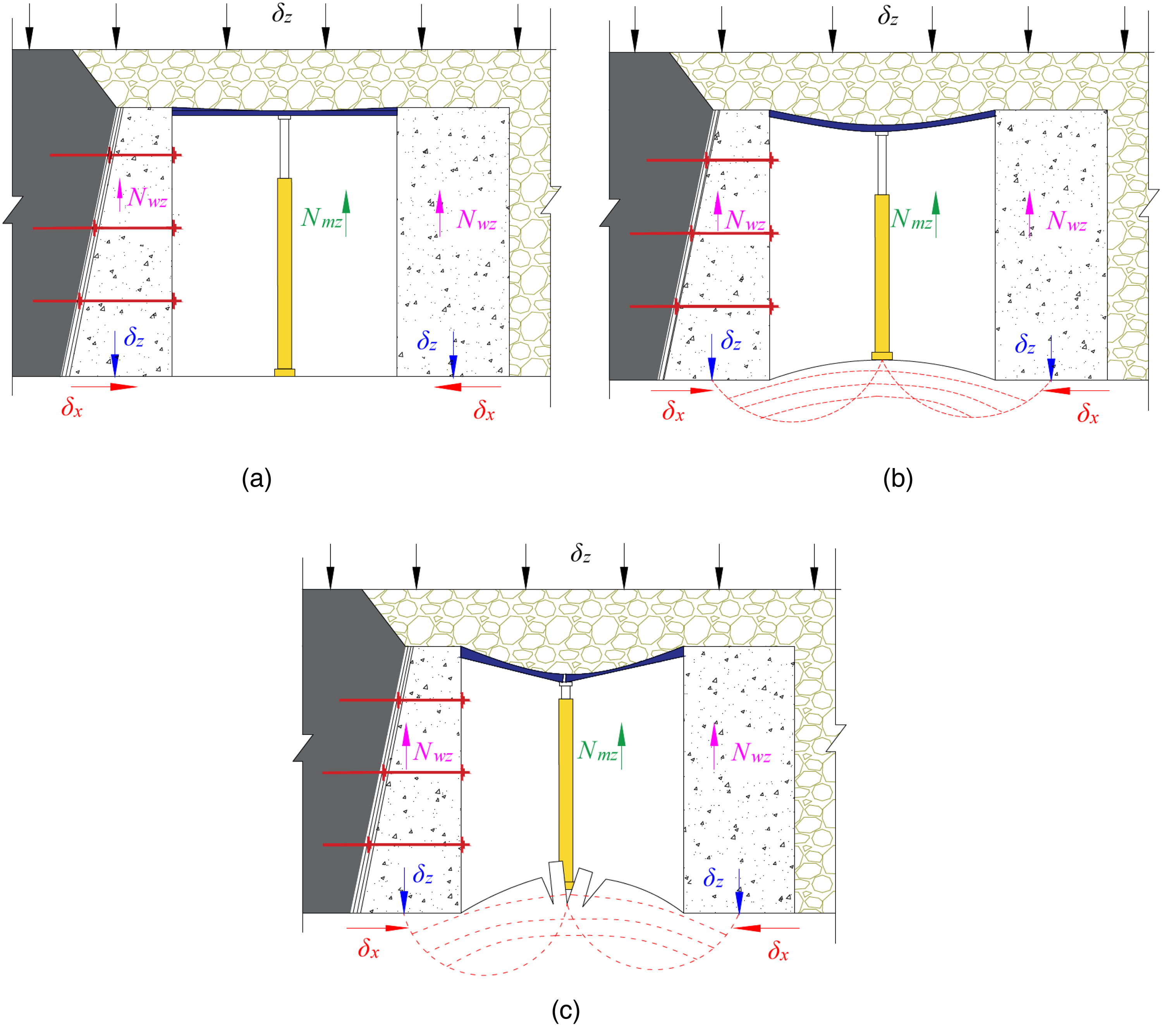
Mechanics stages: (a) Mechanics stage 1, (b) Mechanics stage 2, and (c) Mechanics stage 3.
With the gradual increase of the roof pressure of the roadway, the pressure is transmitted downward along the support structure in the roadway. At this time, the support strength in the roadway is less than the roof pressure, and the roof beam will bend. However, there is still some effective support provided by the support structure in the roadway at this time. Further, the bearing capacity of the walls on both sides is greater than the pressure of the roof of the roadway, and the walls have not yet undergone deformation and plastic failure. The pressure is transmitted downward to the floor coal body and the pillar coal body, where plastic damage occurs inside the coal column, part of the coal body supporting function fails, and the floor coal body is subject to downward stress. In addition, under the action of the horizontal stress caused by the extrusion of the coal body, the weak point of the support in the roadway bulges slowly, and the phenomenon of floor bottom drum occurs at this time. Mechanics stage 2 is shown in Figure 19(b).
Mechanics stage 3: Supporting strength in the middle of the roadway Nmz< roof pressure δz<roadway wall supporting strength Nwz
Affected by the concentrated stress of the roadway at the special stage of gob-side entry retention, the pressure of the roadway roof increases abnormally, with a relatively fast growth rate. The roof pressure is transmitted downward along the support structure in the roadway, and the roadway exhibits a large dynamic pressure phenomenon. The support strength in the roadway is less than the roof pressure, the roadway roof beam is broken by the bending force, and the single live column in the roadway is stuck. The walls on both sides exhibit subsidence, small-area slicing, and shearing; some walls have moved closer to the roadway. At this stage, the floor coal body is subjected to a large vertical stress. At the same time, the coal pillar and coal body are seriously damaged, and the horizontal stress caused by the coal body being squeezed increases. At this time, the floor of the roadway, with a small kick drum in the previous stage, is squeezed and damaged again by the high-level stress, and the damaged rock mass pours into the roadway, resulting in a large kick-drum area. The force of mechanics stage 3 is shown in Figure 19(c).
Roadway optimization and re-mining support
Roadway support optimization
The roof of the 0102402 working face is a metal mesh false roof, and the flexible formwork concrete walls are poured on both sides of the roadway. To reduce the damage to the roadway and the flexible formwork wall owing to the mining pressure of the lower section of the working face, and to prevent the impact of the roof collapse on the flexible formwork wall, it is necessary to optimize the roadway retention support.
With the working face mining up to the 240 m position of the gob-side entry retention, the roadway passes through the No. 3 return air connection roadway, where the roadways intersect to form a large section. To ensure sufficient support, the flexible formwork wall at this point is optimized as a rectangular flexible formwork of 3.0 m (length) × 3.2 m (height) × 2.0 m (width). The φ20 mm×2100 mm double-headed anchor bolts are pierced at the reserved holes of the flexible formwork. Wooden stacks are set up in the No. 3 return air communication lane, and the wall is poured close to these stacks. According to the monitoring of mine pressure and the strength of the wall, the withdrawal plan of the single hydraulic prop for the lag temporary support is optimized. After the lagging working face distance becomes 60 m, the single hydraulic props supported on both sides of the wall can be withdrawn, and the single hydraulic props supported by a row in the middle of the roadway can also be alternately withdrawn. After the lagging working face distance reaches 100 m, the remaining single hydraulic props in the middle row of the roadway can be completely withdrawn. Before supporting the lag single hydraulic prop, a single row of road wood can be laid on the bottom plate, along the direction of the roadway. This can control the bottom drilling of the single hydraulic prop, enhancing the supporting strength of the single hydraulic prop and reducing the bottom drilling phenomenon of the roadway bottom drum and the single hydraulic prop.
Control scheme of the rock surrounding the roadway
By analyzing the roadway deformation and dynamic pressure law of the gob-side entry retention in the 0102402 working face of the Baijigou Coal Mine at different stages, the deformation mechanism of the gob-side entry retention in the super-thick coal seam layered mining is obtained. During the mining process of the 0102103 working face, the conditions of each stage of the retention roadway affected by the mining dynamic pressure were estimated, and the support scheme for the mining of the 010203 working face was proposed, this scheme was implemented according to the different deformation conditions of the retention roadway. The roadway support section is shown in Figure 20.
Scheme 1
Plane diagram of roadway supports.
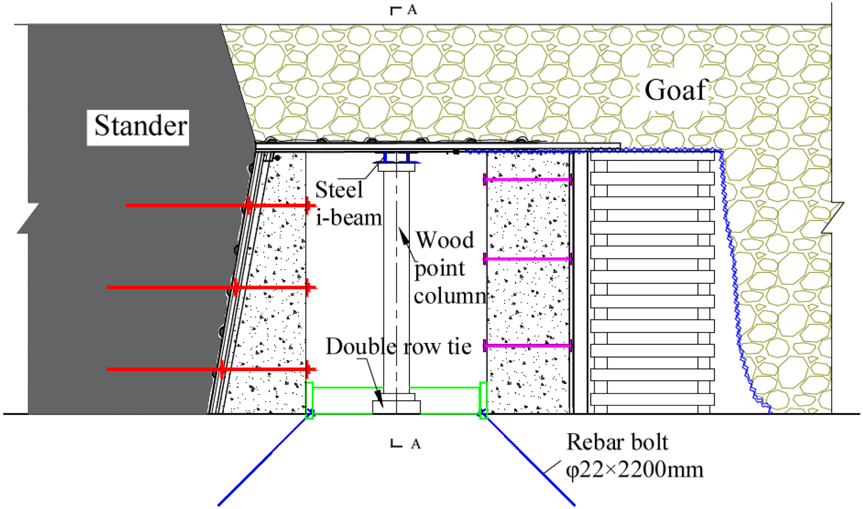
In the first stage of gob-side entry retention, the coal pillar between the roadway and the 010203 working face is wider. According to the monitoring of roadway retention, the deformation of the roadway is small and stable. Therefore, this section of roadway is supported by double-row I-beam beams and wooden point columns. Two single hydraulic props were installed every 10 m in the support section for pressure monitoring, and C15 concrete shotcrete was used for the flexible formwork walls, roofs, and steel beams in the roadway, then, measuring points were arranged on the roadway after the shotcrete. During the mining period of the 0102103 working face, the roadway was monitored regularly.
Scheme 2
Scheme 3
From the second stage of gob-side entry retention (near the opening of the 0102103 working face) to the mining of the working face to 80 m, the coal pillar of the working face becomes narrower. In addition, the support pressure of the 0102103 working face has a dynamic pressure influence on the roadway. It is necessary to increase the support strength of the roadway, at this stage. To prevent the excavation of the 0102103 working face from aggravating the bottom of the roadway, bolts are set at the feet of the two sets of flexible formwork walls along the direction of the roadway.
For the roadway with the two walls moving closer than 200 mm after roadway retention, on the basis of the support strength of Scheme 2, a base beam is set up to limit the relative displacement of the wall in the roadway. The basic support is the same as that in Scheme 1. In the roadway where the distance between the two walls is more than 200 mm, the base plate wood point column beam is used for support. The diameter of the beam is 200 mm. The two ends are pressed against the bottom end of the flexible formwork wall. The length is determined according to the width of the roadway. The wooden point column and the wall are in solid contact with wooden pallets, with a distance of 800 mm.
Conclusions
At present, there is a lack of reliable research on the application of flexible formwork concrete supports to the study of layered entry retention and surrounding rock laws at the bottom of extra-thick coal seams. In this study, gob-side entry retention technology for flexible formwork concrete was successfully used—for the first time, to the best of our knowledge—under the condition of stratified mining of extra-thick coal seams, and the double-flexible formwork wall support technology was proposed, which exhibited good performance. This shows that the application of this technology is feasible under the condition that small coal pillars are left in the layered mining of extra-thick coal seams. Finally, the following results are obtained:
According to the support principle, the joint support of the flexible formwork concrete wall and anchor cables is proposed to reinforce small coal pillars. The design scheme for the gob-side entry retention of “flexible formwork concrete double wall + I-beam shed” at the bottom of the layered mining of extra-thick coal seams is further proposed. Finally, the retention roadway still meets the requirements for the use of gas drainage roadways under the influence of multiple mining dynamic pressures. The roadway deformation of the extra-thick coal seam in the Baijigou Coal Mine can be divided into four stages. The working faces of the first two stages are located below the in-situ coal body. The two-stage retention roadway exhibits the phenomenon of a long pressure stability period and continuous pressure increase, but the overall pressure exhibits a certain periodic regularity. The latter two stages are affected by the goaf of the overlying coal seam and the three-layer mining on this working face. The roadway pressure increases significantly, and the roadway pressure and deformation are generally greater than those of the roadway in the first two stages. The appearance law of mine pressure in the roadway is essentially “pressurized section – peak section – pressure stabilization section”. According to the four deformation stages, the three mechanical stages of roadway deformation are summarized as follows: (1) δz<Nmz<<Nwz; (2) Nmz <δz << Nwz; (3) Nmz < δz < Nwz. Based on the analysis of the roadway deformation and dynamic pressure law of the gob-side retention roadway in the 0102402 working face of the Baijigou Coal Mine at different stages, a roadway support optimization scheme is proposed. According to the optimization scheme, three re-mining schemes are put forward through the monitoring and deformation analysis of the 600 m roadway of retention entry, and it is applied to the roadway reuse stage, such that the surrounding rock deformation of the reused roadway is effectively controlled.
Footnotes
Acknowledgments
The authors would like to thank the Baijigou Coal Mine for the measured data.
Declaration of conflicting interests
The author(s) declared no potential conflicts of interest with respect to the research, authorship, and/or publication of this article.
Funding
The author(s) received no financial support for the research, authorship, and/or publication of this article.