
Abstract
The coal roof of the lower seam of a bifurcated coal seam is always broken and is caused by the mining of the upper seam, which results in difficult support for the coal roof. This seriously affects the safe and efficient mining of the lower seam. Pre-grouting technology is often used to reinforce the regenerated roof in advance to improve its integrity of the roof. In this study, to provide a scientific basis for the layout of surface pre-grouting boreholes, the bifurcated coal seam at the Xutuan coal mine in the Huaibei mining area in China was analyzed. The height and depth of the damage in the coal roof and floor caused by upper seam mining were calculated using theoretical analysis and numerical simulation. The porosity and permeability of the goaf in different positions were calculated by numerical simulation, and the spatial distribution of the porosity and permeability and the slurry diffusion radius of different porosities were determined. Finally, the grouting section and layout of the pre-grouting boreholes were determined. Based on the design scheme, the drilling of the surface boreholes and the addition of the grouting were carried out. The accuracy of the theoretical analysis was verified by field drilling and grouting activity. The research results can provide a basis for the layout of surface pre-grouting boreholes and the selection of the grouting zone in areas of close-distance coal seam mining.
Introduction
Coal is the main energy resource in China. In China, coal mining technology has developed rapidly, and accurate, green, safe, and efficient mining of coal resources has become the main requirement for coal mining in the future (Yuan 2020; Wang et al., 2020a; Yuan and Zhang 2020). The roof stability of the working face is the key factor to ensure the safe and efficient mining of coal resources. In recent years, accidents caused by roof instability have become common, resulting in huge economic losses and casualties (Yuan et al., 2018). Coal seam bifurcation is a common phenomenon in Shendong, Henan, Shanxi, Shandong, Jiangsu, Anhui, and other major mining areas in China (Liu and Sun 2021). During the process of coal seam formation, changes in the sedimentary environment can lead to coal seam bifurcation within a short distance, and the thickness of the coal seam can change significantly. In the coalescence area, the thickness of the coal seam is larger, while in the bifurcation area, there are two or even multi-layer thin coal seams, and the spacing between the upper and lower coal seam changes greatly, thereby bringing great challenges to the selection and implementation of mining technology. This is especially so in the bifurcation area, where due to the mining of the upper layer, the roof structure of the lower coal seam gets broken, which seriously restricts the safe and efficient production of coal resources.
Domestic and foreign scholars have conducted many studies regarding close-distance bifurcated coal seam mining and treatments for broken roofs. Wang et al. measured the floor failure depth at the Xuzhuang coal mine in the Datun mining area using the DC electrical method and proposed an estimation method for the floor failure depth of close-distance coal seams (Wang et al., 2020b). Zheng used a similar material simulation method to study the mining of shallow, buried, close-distance coal seams in a mountainous area and obtained the basic characteristics of roof failure and movement (Zheng 2011). Zha et al. (2012) calculated the floor failure depth of an upper coal seam by numerical simulation and similar material simulation and proposed an underground grouting method to strengthen the broken roof of the underlying coal seam. Wang et al. (2020b) studied the failure characteristics of the coal roof and floor during close-distance coal seam mining using numerical simulation and similar material simulation and proposed that the interlayer thickness between the upper and lower coal seams was the key factor affecting the failure of the coal roof and floor (Wang et al., 2020b). Based on hydraulic fracturing theory, Qian et al. (2017) adopted a surface pre-grouting method to reinforce the broken roof, which improved the stability of the broken roof and reduced the roof displacement significantly during the mining period (Qian et al. (2017). Strømsvik and Gammelsæter (2020) used the surface pre-grouting method to strengthen the broken surrounding rock mass of a roadway, which reduced the permeability of the broken rock, and effectively reduced roadway water inflow and the instability of the surrounding rock (Strømsvik and Gammelsæter 2020). The secondary failure characteristics and mechanism of support instability caused by lower seam mining were studied by Yang et al. (2020) based on similar simulation and theoretical analysis. The compaction state and the roof caving of the regenerated roof were obtained (Yang et al., 2020). Cheng et al. (2016) used a similar material simulation experiment to study the stress evolution and fracture development characteristics of surrounding rock under short-distance coal seam mining in the Shaqu coal mine. The research results guided the layout of gas drainage boreholes (Cheng et al., 2016). In another study, the underground grouting method was used to reform the broken roof caused by upper seam mining, and the safe mining of the lower seam was achieved without needing to use wire mesh (Li and Wang, 2009; Li, 2011).
Current research on the mining of close-distance coal seams and the treatment of broken roofs mainly focuses on the evolution of stope stress, the failure characteristics of the roof and floor, broken surrounding rock support, and gas drainage and treatment under repeated mining. Underground grouting is affected by the site, and the grouting equipment is relatively simple. Surface grouting is not affected by the underground environment and, can fully leverage the surface drilling depth to improve the grouting pressure. Some scholars have studied surface pre-grouting, but there has been little research on the scientific layout of surface grouting boreholes. The layout of surface grouting boreholes is often based on practical experience and lacks a scientific basis. The layout of grouting boreholes is the key to the success of grouting broken roofs. In addition, the scientific basis for choosing the grouting section is of great significance to reduce the cost of grouting and improve the grouting effect. In this study, the broken roof of the lower seam of a bifurcated coal seam was analyzed, and theoretical calculation and numerical simulation methods were used to study the mining characteristics of the roof and floor and the upper seam's goaf porosity. The structure of the regenerated roof of the lower seam and the spatial distribution of the permeability were obtained, and the slurry diffusion radius of different porosities was determined by numerical simulation.
Geological survey of the study area
The Xutuan coal mine, located in the Huaibei mining area of Anhui province in eastern China, is a monoclinic structure with a nearly north-south strike and east dip; the secondary folds are developed, resulting in a wavy undulation of the coal seams (Figure 1). The stratum of the Huaibei mining area belongs to the North China type, and the main coal seam is the No.7 coal seam which belongs to the Lower Shihezi Formation of the Permian system. Affected by the sedimentary environment, the No.7 coal seam is divided into the No.71 coal seam and the No.72 coal seam in the bifurcation zone; however, it is a single coal seam without gangue in the merging area (Figure 2). The thicknesses of the No.71 and No.72 seams are 0–3.72 m (with an average of 1.86 m) and 0–8.6 m (with an average of 3.36 m), respectively. The working face of No. 72210 is the preparatory working face of the mine and is located below working face No. 71212, which was mined in 2014 (Figure 1). The coal seam in working face No. 72210 is 6.5 ft (2 m) thick on average, dips 10° on average, and its elevation is −510 to −560 m with an average of −535 m. The roof is mainly composed of mudstone and sandy mudstone, which is categorized as soft rock. The ground elevation is +25.90 m, and the thickness of the soft stratigraphic layer of Quaternary age is 348.65 m. The depth of 500 m in the middle part of working face No. 72210 is the bifurcation area of the No. 7 coal seam. The gangue is mainly mudstone, with a thickness of 0–9.02 m and an average thickness of 5.73 m. The roof of working face No. 72210 has been damaged due to the mining of the upper working face of No. 71212. To ensure the safe mining of working face No. 72210, the surface pre-grouting method has been used to improve the integrity of the broken roof.
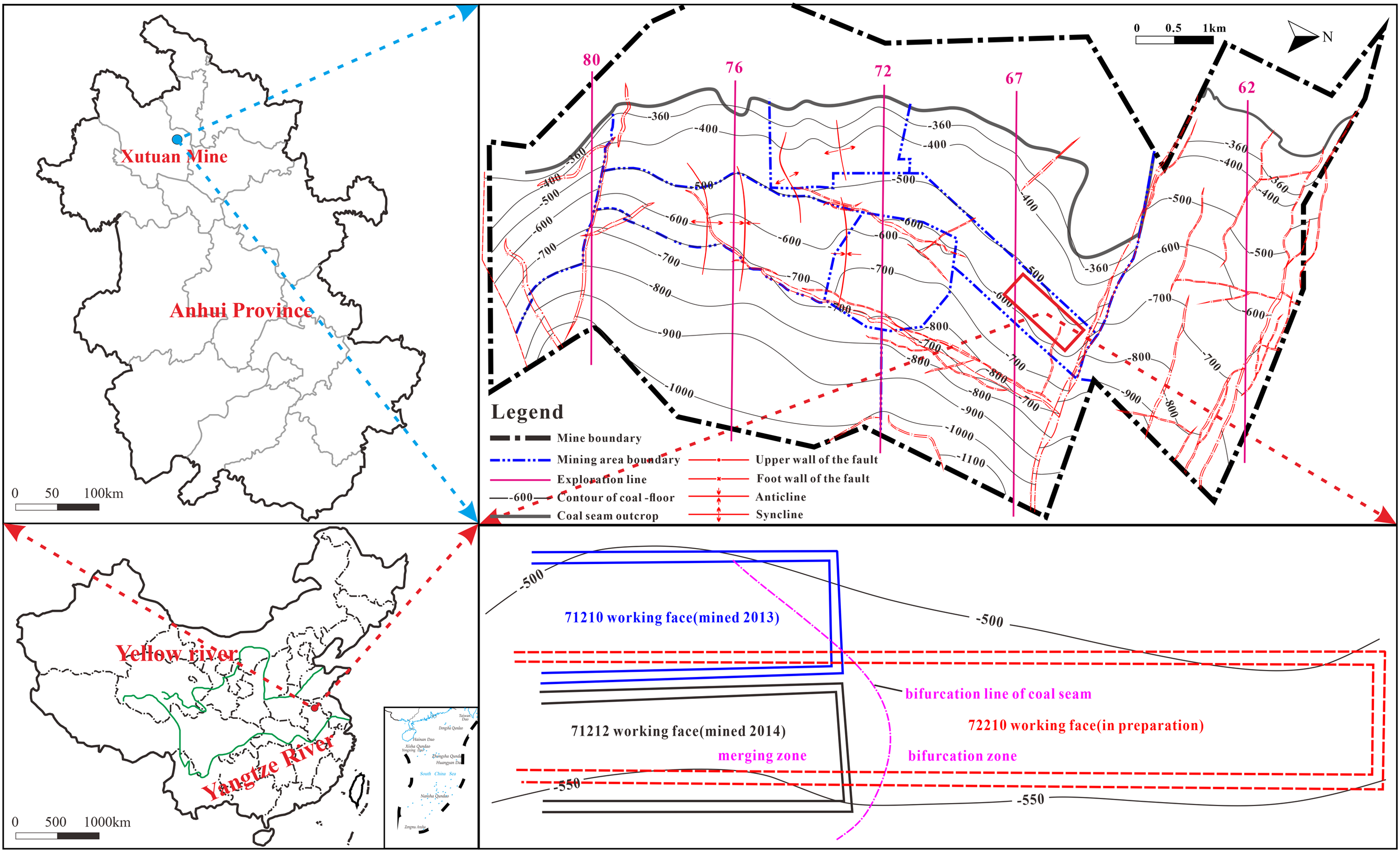
Position and coal-seam contour map of the Xutuan coal mine.
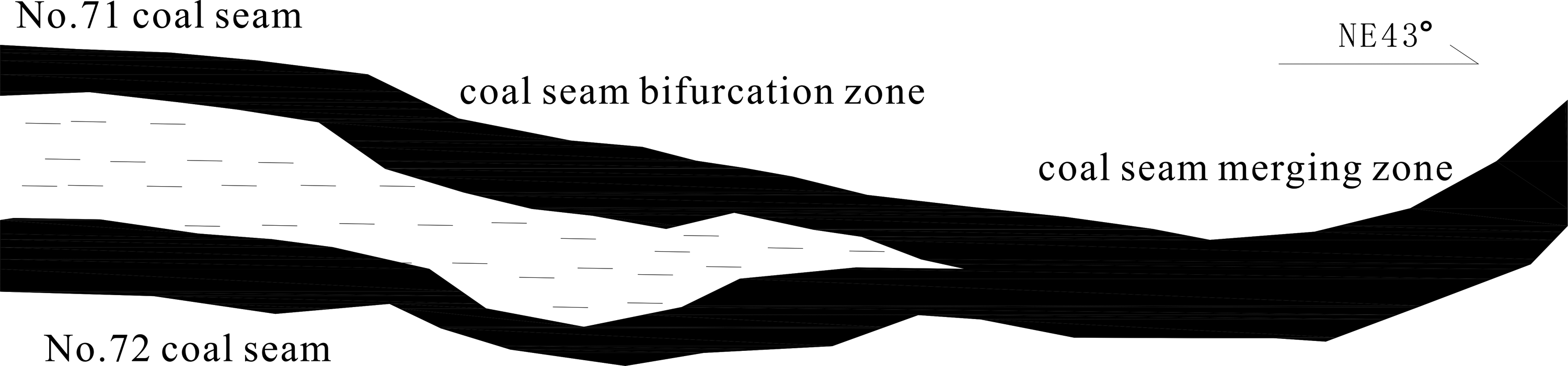
Sketch map of the coal seam bifurcation and merge zones.
Results and analysis
Mining characteristics of the coal roof and floor of the upper working face
After coal mining, three zones have been formed in the vertical direction of the coal roof – the caving zone, the fractured zone, and the continuous zone (Figure 3) (Qiao et al., 2011). The caving zone and the fractured zone, called the water-flowing fracture zone, are the key factors affecting the stability of the lower coal seam's roof. Numerical simulation and theoretical analysis were used to investigate the height of the water-flowing fracture zone and the floor failure depth of the upper working face No.71212.
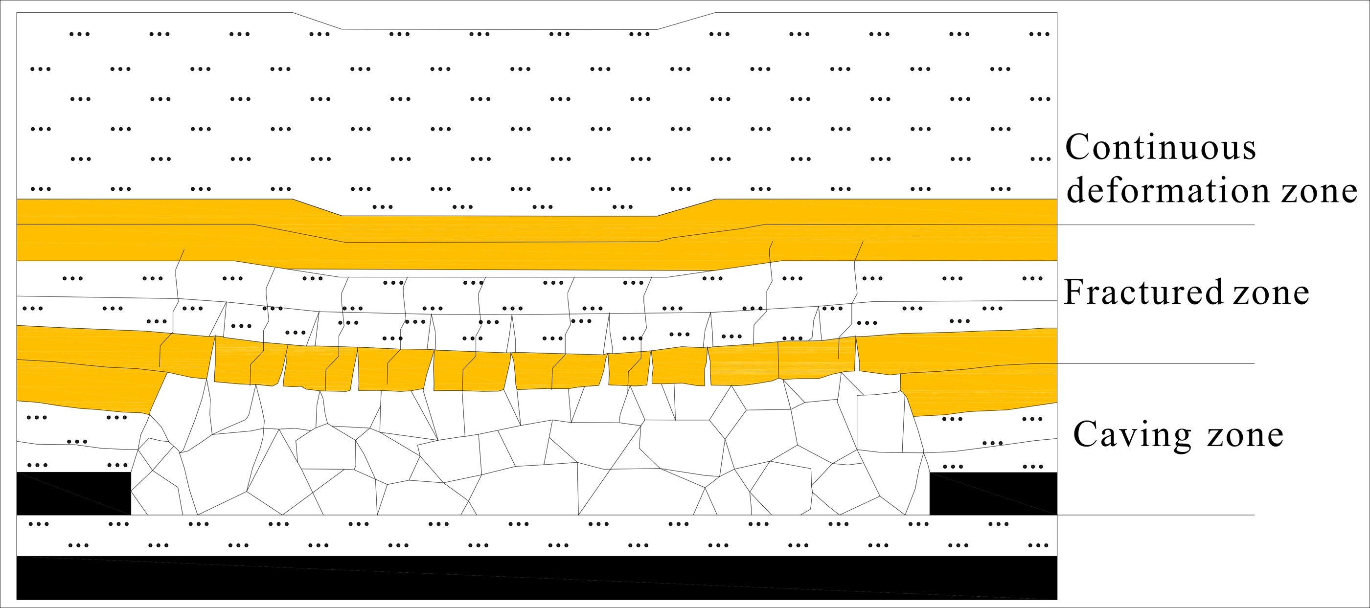
Sketch map of the three-zone coal roof.
Numerical simulation
The FLAC3D software was used to build the model of working face No.71212 based on its real geological characteristics. The size of the model is a 300 m × 290 m × 90 m (X × Y × Z) block with an average coal seam thickness of 2 m (Figure 4(a)); the width of the working face is 165 m (Figure 4(b)). The average stratigraphic dip of working face was 10°, so the horizontal stratum was used for equivalent analysis. Vertical stress field is the main stress type in Xutuan coal mine (Zha et al., 2012). The average depth of the working face is about 560 m, and the height of the overburden strata in the model is only 50 m. Therefore, the thickness of the overburden material above the model is about 510 m. This gives an equivalent vertical overburden pressure of 12.75 MPa, and this is applied uniformly on the upper boundary of the model. The lower boundary condition of the model is assumed to be fixed with a zero-displacement boundary condition in all three directions. For the left and right boundaries of the model that are adjacent to the solid rock, vertical roller boundaries are imposed which allow movement only in the vertical direction.
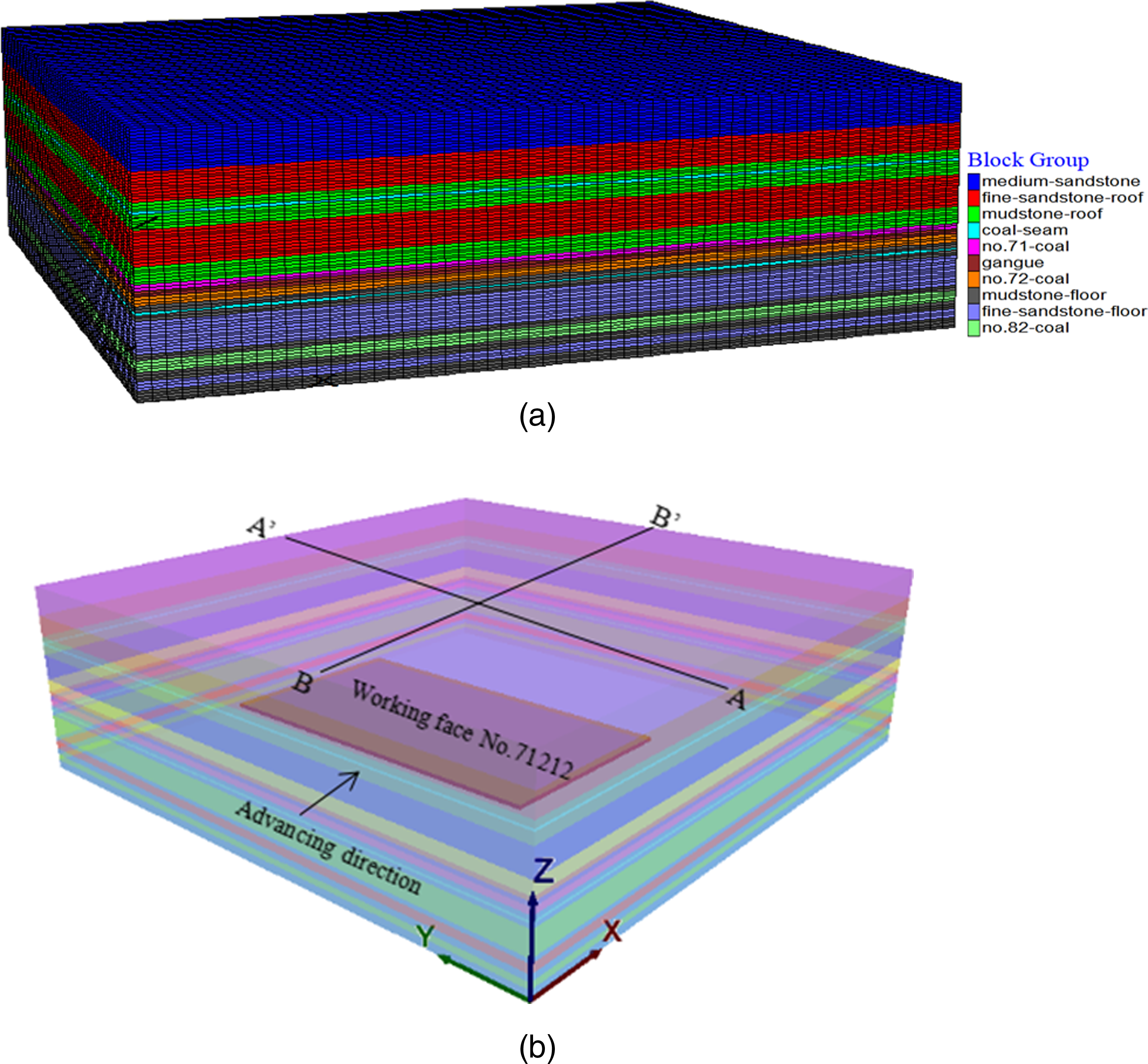
Numerical model of the study area. (a) Model, (b) Position of working face No.71212.
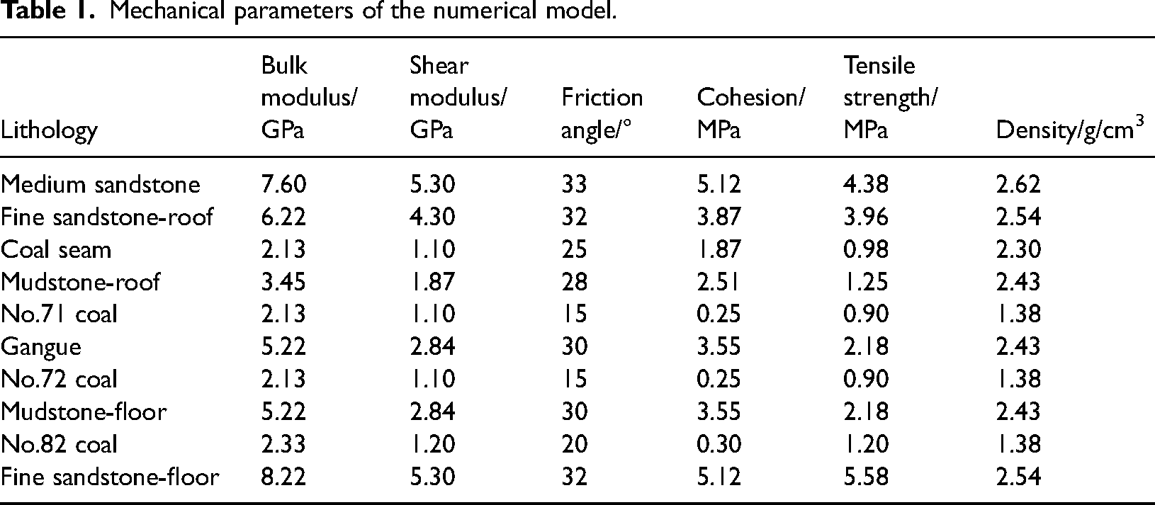
In the numerical model, mining started 50 m from the model boundary in the X direction to eliminate the boundary effect, and the coal pillar width in the Y direction was 45 m and 80 m, respectively. The first weighting and the periodic weighting of the main roof were 30 m and 20 m, respectively. The Mohr–Coulomb criterion was selected as the failure criterion of the model. The mechanical parameters of the model are shown in Table 1.
Effects of working face mining on stress distribution in the rock: Figure 5 shows the mining stress distribution after the completion of mining. Stress was redistributed after the coal seam was mined. The abutment pressure influence area was found within a certain distance on both sides of the coal face. Obvious pressure relief phenomena appeared in certain areas of the coal roof and floor of the goaf. The maximum abutment pressure of the coal face after mining was about 36 MPa, which is higher than the initial stress of 14 MPa. The stress concentration factor was about 2.5. Effects of working face mining on plastic zone development in the rock: Figure 6 shows the plastic zone distribution after the completion of mining. The coal seam and surrounding rock were cracked and broken when the abutment pressure exceeded the coal and rock plastic limit. A plastic zone appeared in the coal roof and floor and was caused by the abutment stress. Based on the stress state of the roof in the goaf, the failure type of the caving zone is mainly a tensile failure, while the failure type of the fractured zone is mainly tensile-shear composite failure (Meng et al., 2016). Then, the height of the caving zone and fractured zone was determined, which are 8 m and 26 m, respectively. The fractured zone was saddle-shaped, and the failure depth of the coal floor was about 10 m.
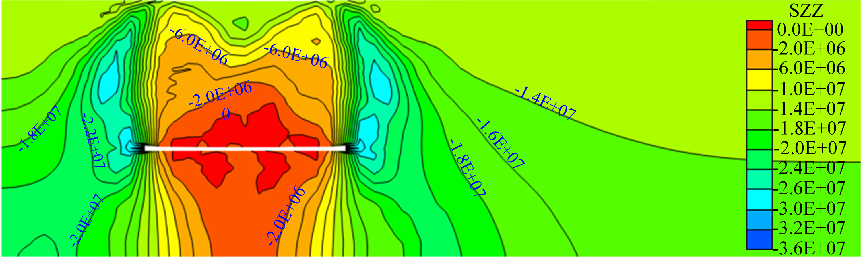
Counter of mining stress (BB’ profile).
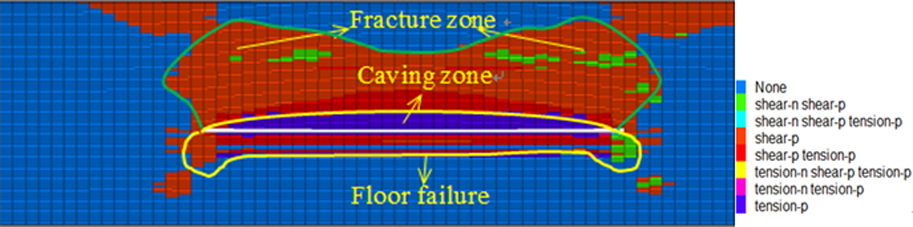
Distribution of the plastic zone after mining.
Mechanical parameters of the numerical model.
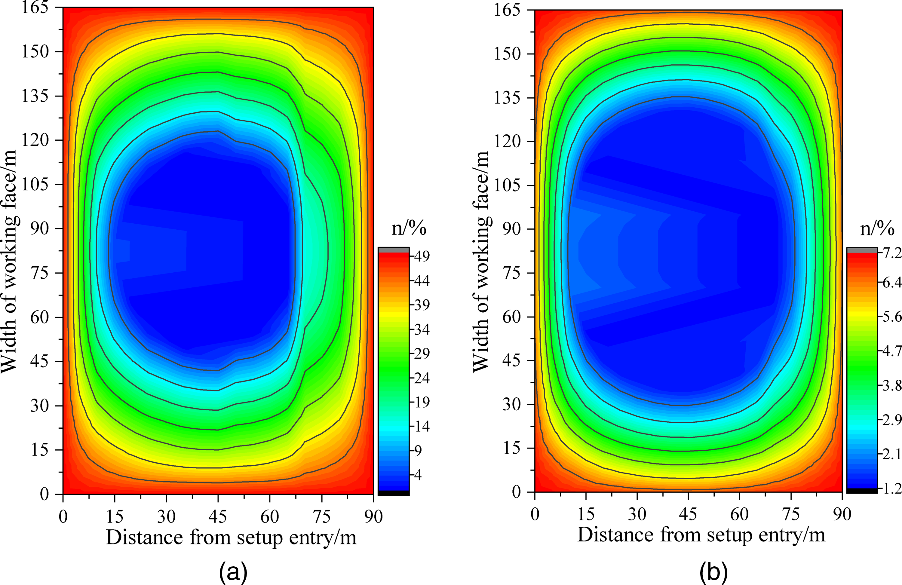
Theoretical calculation
According to the technical specifications of coal mining under buildings (constructions), railways, and water bodies of China, the height of the caving zone and fractured zone under soft overburden strata can be calculated from equation (1) as:
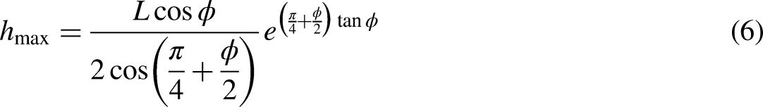
The height of the caving zone of working face No.71212 is 5.50–6.68 m with an average height of 6 m, and the height of the fractured zone is 20.55–23.42 m with an average height of 22 m. The failure depth of the coal floor was calculated based on the Slip Line Field Theory method (Sun et al., 2017). The coal floor is cracked and broken when the abutment pressure exceeds the rock plastic limit. The plastic zone is connected by pieces, and floor heave occurs in the goaf floor behind the working face. The floor rock stratum with plastic deformation moves into the goaf to form a continuous slip field, and there is a sliding surface between the rock mass without plastic damage as shown in Figure 7.
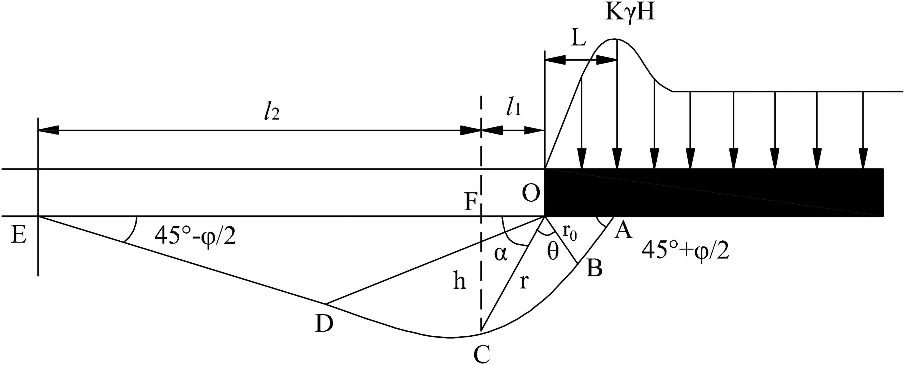
Mechanical model of the plastic failure depth of the coal floor.
It can be seen from Figure 7 that the plastic failure zone of the floor is composed of three parts: the limit zone (△OAB), the transition zone (△OBD), and the passive zone (△ODE). The limit zone is the rock mass in the action area of the abutment pressure. When the abutment pressure exceeds the ultimate strength of the rock mass, plastic deformation produces lateral expansion due to the vertical stress on the rock mass. The expanded rock mass compresses the rock mass in the transition zone and transmits the stress to the transition zone. The rock mass in the transition area compresses the rock mass in the passive area. There is a free face in the goaf; thus, the rock mass expands into the goaf after being compressed. The slip lines of the three zones are composed of two groups of straight lines, in which the active zone and the passive zone are composed of radial lines from point O, and the slip line of the floor deformation and failure in the transition zone is a logarithmic spiral: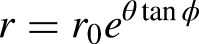


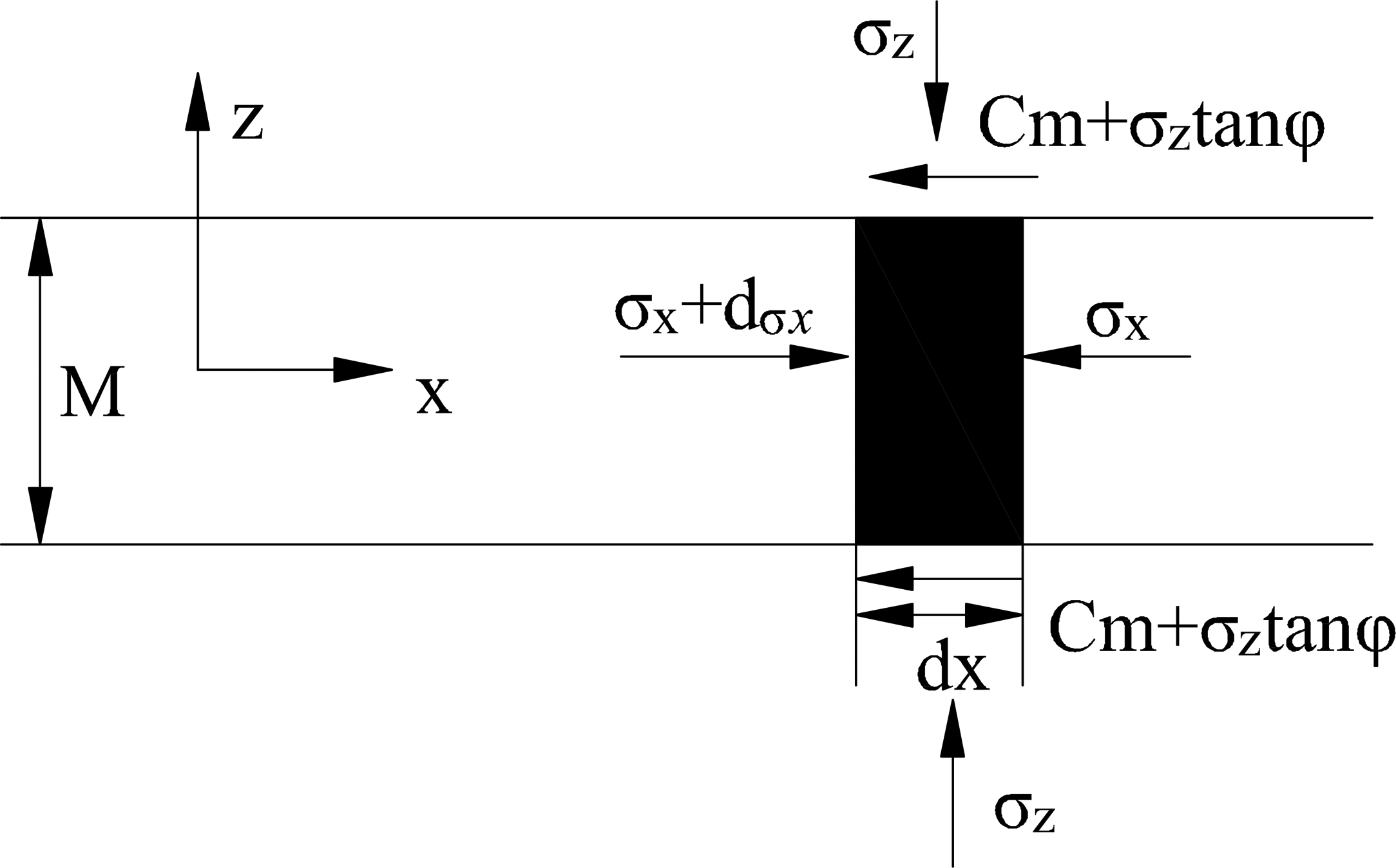
Mechanical model of the limit equilibrium zone of the coal wall.
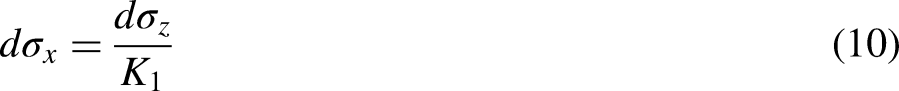
When the differential element is in a state of force equilibrium, the resultant force along with X direction is 0, and the force state can be expressed as equation (7):


According to the actual geological data from the 71212 working face, M = 2 m,
The results of the theoretical calculation are quite consistent with the numerical simulation. The results show that the height of fractured zone of the roof was about 22–26 m, and the failure depth of the floor was about 10 m after mining working face No.71212.
The coal roof and floor of working face No.71212 show obvious damage caused by mining, and the coal floor failure zone of working face No.71212 affects the lower working face No.72210 and its floor in the zone where the width of the gangue is thin. After the roof got damaged, it covered the floor of working face No.71212. The caving zone, fractured zone, and floor failure zone of working face No.71212 constituted the regenerated roof of working face No.72210. The regenerated roof was mainly composed of broken and fractured rock; therefore, the structure of the regenerated roof was poor. To ensure the safe and efficient mining of the lower working face, it was necessary to reinforce the broken regenerated roof by surface pre-grouting. The maximum thickness of the gangue between the upper and lower coal seam was only 9 m in the bifurcation zone; however, the floor failure depth of the upper working face was 10 m, which meant that there was no complete rock structure between the upper and lower working faces. Therefore, the range of the pre-grouting section was the total bifurcation area of the No.7 coal seam on the plane.
Porosity and permeability characteristics of the upper working face
Porosity characteristics
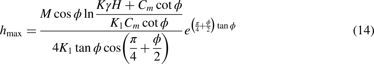
The overburden strata of the working face were damaged after the formation of the goaf, and the broken rock accumulated disorderly in the goaf. The porosity distribution characteristics of the broken rock were different in the vertical and horizontal directions. The bulking factor (kp) is defined as the ratio of the volume of the broken rock strata to the original volume of the same strata before it broke and caved (Wang et al., 2018). The porosity of the broken rock (n) is defined as the ratio of the volume of pores between rock blocks in the broken state to the total volume of the broken rock. According to the definition of porosity and the bulking factor of the broken rock, the relationship between kpand n is as follows: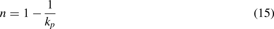

Then, the porosity (n) can be calculated by equation (15).
To observe the displacement of the overburden strata, two monitoring lines were laid on the established numerical model, as shown in Figure 9.
Schematic displacement monitoring.
Before the excavation in the model, two monitoring lines were laid at 2 m and 25 m above the coal roof, which represent the location of the caving zone and the fractured zone, respectively. During the excavation process, the displacement of the model was monitored. The deformation data of the model were collected according to the first weighting and periodic weighting. By substituting the monitoring data into equations (16) and (15), the distribution of porosity in each stage of mining was obtained. The porosity at different heights is shown in Figure 10.
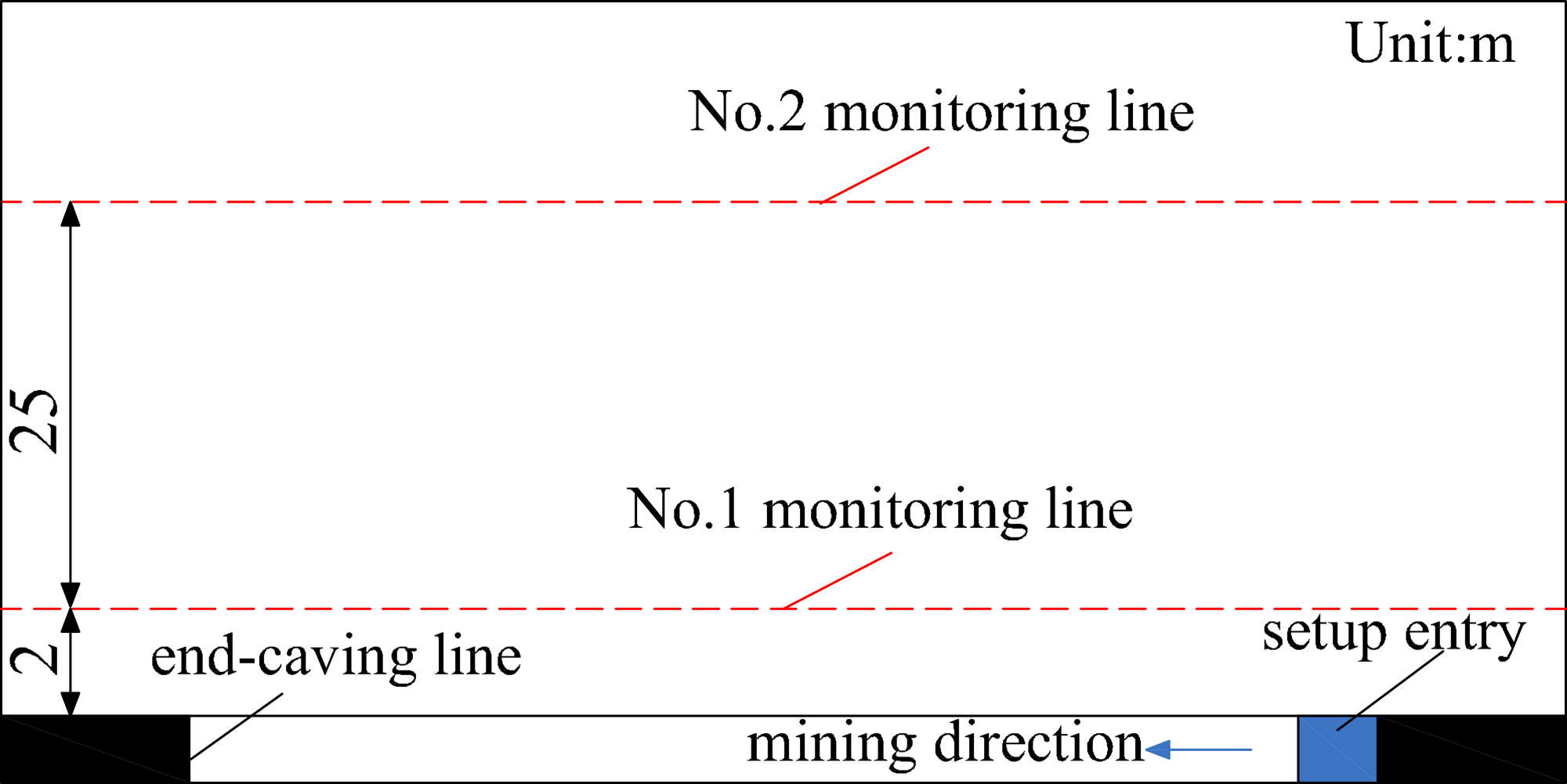
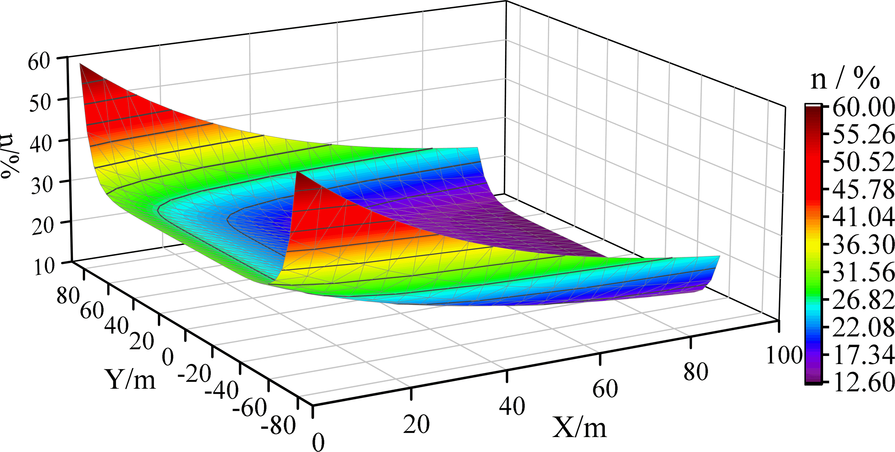
Porosity of the caving and fractured zones in the goaf. (a) Caving zone, (b) Fractured zone.
The porosity distribution of the caving zone and the fractured zone is basically the same, which is an O-shape on the plane. The distribution of porosity shows that the porosity is large at the setup entry, the end caving line, and the coal walls of the head entry and tail entry, especially at the four corners of the end caving line and the coal wall of the setup entry; the porosity is small in the middle of the goaf. The porosity at both ends of the caving zone at 2 m above the roof is the largest, at nearly 50%. The porosity at the center of the caving zone is smaller than 10%, caused by the compaction of broken rock. The porosity at both ends of the caving zone at 25 m above the roof is only 7.2%, and the porosity of the central part is only 3%. Therefore, the porosity of the caving zone is significantly higher than that of the fractured zone.
The rock in the caving zone is the accumulation of broken rocks. Due to insufficient compaction, the broken rocks have large porosity and good plane connectivity, which is the main reason for large permeability in caving zone. The rock structure in the fractured zone can be regarded as Voussoir beam (Qiao et al., 2011). The permeability of fractured rock is mainly related to the fissure opening. The fissure opening is wide at the bottom and narrow at the top, and the connectivity on the plane is poor. Under the effect of lateral compression, the fissures gradually close from the roof upwards, so the permeability of the fractured zone is lower than that of the caving zone.
According to field observation data and empirical formulae, we make the strike direction of the goaf as the x-axis, the width direction of the working face as the y-axis, and we take the midpoint of the coal wall width of the working face as the coordinate origin to establish the porosity coordinate system of the goaf caving zone as equation (17) to equation (19) show (MacDonald et al., 1991):


The working face 71212 of the Xutuan coal mine was taken as an example, and the width of this working face is 165 m. The porosity of the goaf was calculated using equation (19) when the face had advanced to 90 m. The porosity distribution is shown in Figure 11.
Porosity distribution of the caving zone.
As seen in Figure 11, the porosity near the coal wall of the setup entry and on both sides of the working face is the largest and it gradually decreases towards the goaf. The porosity distribution is basically consistent with the numerical simulation results, which verifies the accuracy of the numerical simulation results.
Permeability characteristics
To describe the permeability of the broken rock in the caving zone, the broken rock is usually regarded as a homogeneous porous medium, and the relationship between porosity and permeability can be used for description; the permeability can be calculated using Kozeny theory as equation (20) shows (Pappas and Mark C, 1993):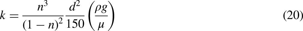
The diameter of the broken rock in the caving zone ranges from 40 to 550 mm and is mainly about 50 cm, so the average diameter (d) is 0.5 m (Pappas and Mark, 1993). The dynamic viscosity
Permeability of the caving and fractured zones of the goaf. (a) Caving zone, (b) Fractured zone.
As seen in Figure 12, the distribution of permeability is consistent with that of the porosity, which is also an O-shape. The permeability of the caving zone is greater than that of the fractured zone, and the permeability of the two zones can differ by more than three orders of magnitude. Therefore, the caving zone of the goaf is the main place for slurry diffusion and migration, and it is the main grouting section. During the periodic caving, the overburden strata caved sequentially from bottom to top in reverse-step shapes and consequently formed a cantilever beam structure over the face. The cantilever beam structure of the overburden strata above the roof at the coal wall of the goaf supported the overburden strata and hindered the compression of the broken rock in the goaf. With the advance of the working face, the permeability decreased due to the compaction of the middle zone of the goaf, while the four corners of the goaf were poorly compacted and high in permeability due to the support of the cantilever beam. Therefore, the permeability was greater at the four corners of the goaf, which shows that the compaction of the broken rock in the goaf had an obvious effect on its permeability. During the grouting activity, the amount of slurry was larger at the inner side of the coal pillar, the setup entry, and the end caving line.
Characteristics of slurry diffusion in the goaf of the upper seam
To guide the layout of the surface pre-grouting boreholes, slurry diffusion was studied. Based on the porosity and permeability results, a numerical model was built using the COMSOL Multiphysics software, and the slurry diffusion radius under different conditions was obtained.
Calculation principle
In Darcy's law of two-phase flow, saturation represents the filling proportion of fluid in a certain area of porous media. The movement of the slurry boundary can be characterized by saturation. A saturation of 1 indicates that the region is completely filled by one of the fluids (slurry). A saturation of 0 indicates that there is no fluid in the region. If the saturation is between 0 and 1, it means that the area is filled with two-phase fluid at the same time. Therefore, the two-phase Darcy's law module in the software can be used to calculate the slurry diffusion radius. When the saturation of the slurry is greater than 0.9, this range can be considered as the slurry diffusion boundary.
Slurry parameters and simulation results
According to the actual grouting project, the grouting slurry was cement-fly ash slurry, which belongs to the Bingham fluid type. The slurry density was 1300 kg/m3 and the viscosity was 0.03 Pa·s. The grouting pressure was 15 MPa. The slurry diffusion radius under different porosities is shown in Figure 13.
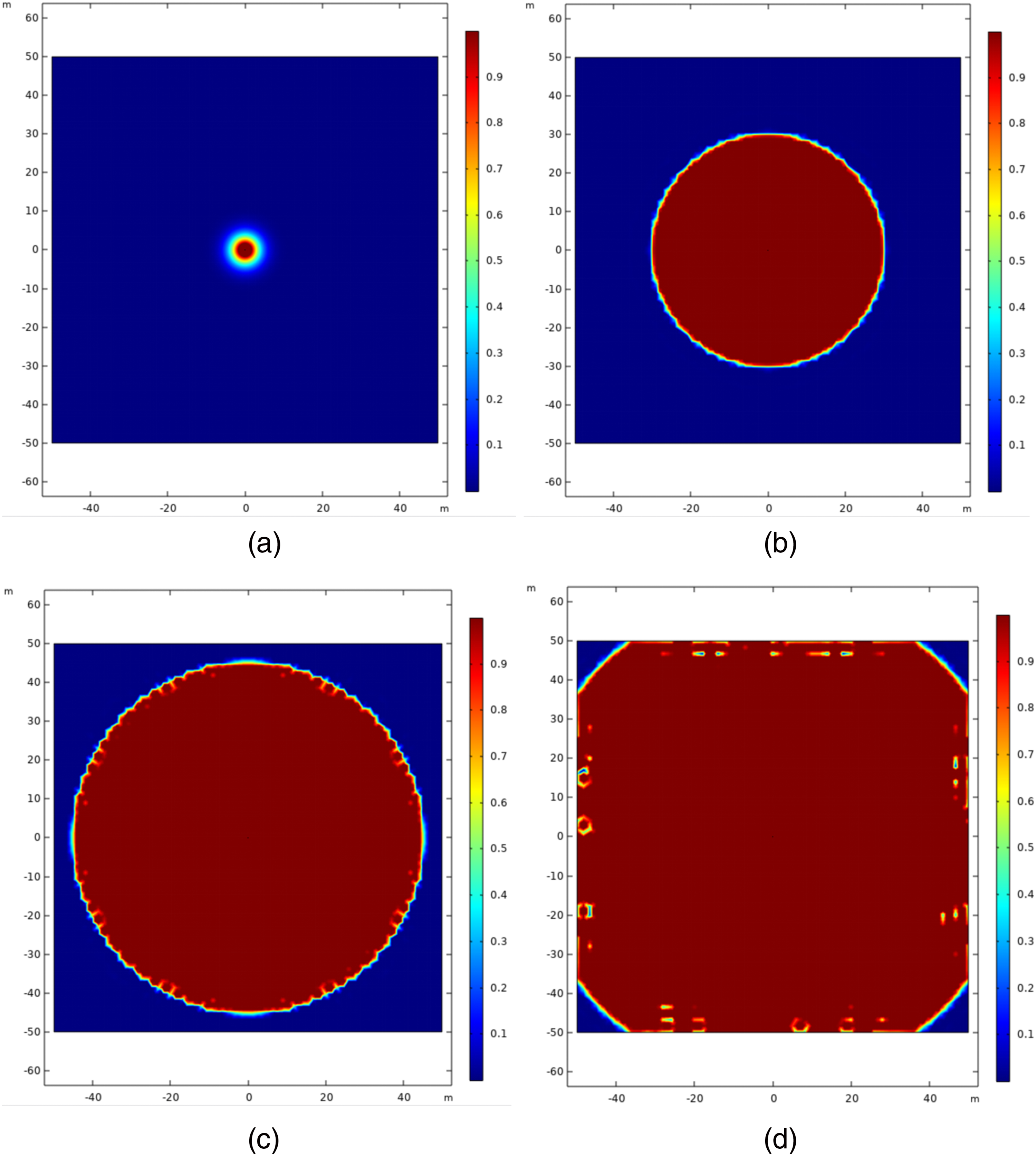
Slurry diffusion radius of different porosities. (a) n = 3%, R = 3.45 m. (b) n = 30%, R = 30.20 m. (c) n = 40%, R = 44.50 m. (d) n = 50%, R = 61.45 m.
The results show that the slurry diffusion radius is closely related to the porosity of the goaf. With the increase in the porosity, the slurry diffusion radius obviously increases. When the porosity increases from 3% to 50%, the slurry diffusion radius increases from 3.45 to 61.45 m. The plane shape of the slurry diffusion depends on the distribution characteristics of the porosity.
Layout of surface pre-grouting boreholes and grouting engineering
Layout of surface pre-grouting boreholes and slurry diffusion range
Based on the distribution characteristics of the porosity and permeability of the goaf, the grouting section and layout of the pre-grouting boreholes were determined. Due to the good compactness and uniform permeability in the middle part of the goaf, long-distance interval drilling along with the coal wall direction and short-distance interval drilling in the middle of the goaf were chosen. A total of nine surface grouting boreholes, numbered from 1# to 9#, were designed, and these are shown in Figure 14. The slurry diffusion shape was controlled by the plane distribution of the permeability in the goaf. The slurry diffusion shape around the coal walls was oval, and its short axis was perpendicular to the coal wall. However, the slurry diffusion in the middle of the goaf was approximately circular because the permeability in this part is basically the same. According to the simulation results of the slurry diffusion radius under different porosities, the slurry diffusion range was delineated as shown in Figure 14. The slurry diffusion range can effectively cover the roof of the lower working face (72210 working face).
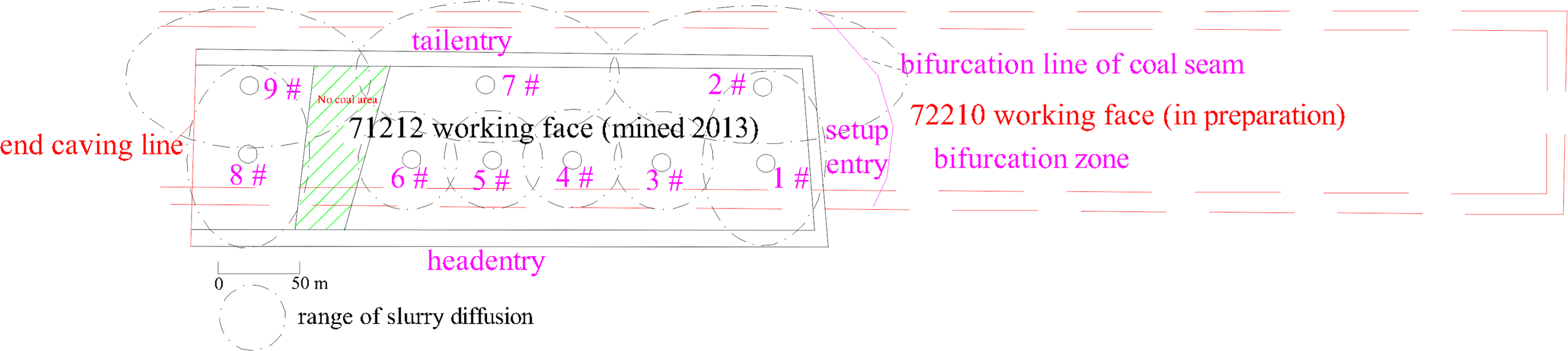
Layout of the boreholes and the slurry diffusion range.
Grouting engineering
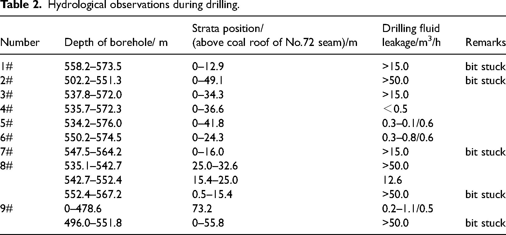
1) Stratum characteristics revealed by drilling: Surface borehole drilling revealed the following stratum characteristics. The hydrological observations during drilling are shown in Table 2. The drilling bit was stuck and obvious drilling fluid leakage occurred in five boreholes, i.e., in 1 #, 2 #, 7 #, 8 #, and 9 #, when drilling to above 20 m of the roof of the No.71 coal seam, which revealed that the stratum in this area was broken and that the compaction degree of the goaf in working face No.71212 was poor. There was no obvious drilling fluid leakage and the drilling process was smooth when drilling till the No.72 coal seam floor in the boreholes arranged in the middle part of the goaf, i.e., in 3 #, 4 #, 5 #, and 6 #, which shows that the stratum integrity at the middle of the working face was good and that the goaf compaction degree was high.
Hydrological observations during drilling.
2) Grouting characteristics: During the grouting engineering process, the difficulty in performing the grouting was as follows:
In the middle and early stage of grouting in the 2#, 8#, and 9# boreholes, the pressure of the borehole orifice was always 0 MPa, while the pressure rose suddenly after the grouting activity to as high as 10 MPa. During the entire grouting process, the grouting pressure of the three boreholes was basically maintained at a low pressure, which indicates that the fractures of the goaf near the three boreholes are extremely well-developed with good connectivity and good injectability; therefore, the grouting could be completed at low pressure. In the early stage of grouting in the 1#, 3#, and 7# boreholes, the grouting pressure began to rise to as high as 2 MPa. The pressure rose to about 8 MPa during the middle and later stages. The grouting pressure fluctuated greatly, and the three boreholes always maintained a certain pressure for grouting. This shows that the grouting area near the three holes had good injectability and developed fractures, but the fracture connectivity was not good, and, therefore, a high grouting pressure needed to be maintained to make the slurry spread further. During the entire grouting process in the 4#, 5#, and 6# boreholes, there was pressure at the borehole orifice all the time. In the early stage of grouting, the pressure was 5–6 MPa, and the pressure was as high as 8 MPa in the middle and later grouting stages. The grouting pressure during the entire grouting process was high, which indicates that the degree of development of the goaf fractures was poor and that the fracture connectivity was not good. High-pressure grouting was needed to improve the connectivity between fractures, and the slurry diffusion range could be larger.
Classification of grouting difficulty in the goaf
Based on the characteristics of the stratum, grouting, and diffusion radius, the goaf of working face 71212 can be divided into three areas: easy grouting area, medium grouting area, and general grouting area. In the easy grouting area, the diffusion radius of the slurry was more than 40 m, and the maximum was 60 m. In this area, the slurry was easy to move, and it was easy to fill the pores quickly. The grouting project could be completed under low pressure, and the pressure rose rapidly in the later stage of grouting. This area is mainly distributed in the corners, which consists of the roadway, setup entry, and the end caving line. In the medium grouting area, the diffusion radius of the slurry was about 30 m. The slurry seepage was good under a certain grouting pressure. The area and seepage space were large and the main location for slurry seepage and occurrence. In the early stage of grouting, the grouting pressure began to rise, and the grouting activity could be completed under moderate pressure. This area is mainly distributed along with the roadway, setup entry, and the end caving line. In the general grouting area, the diffusion radius of the slurry was less than 30 m. There was a large pressure at the borehole orifice during the early stage of the grouting activity, and the pressure of the borehole orifice rose easily. The grouting works could be completed under high pressure and this area is mainly distributed in the middle part of the goaf where the compaction is good.
Conclusions
Theoretical calculations and numerical simulations were used to study the failure characteristics of the coal roof and floor caused by upper coal seam mining. The average height of the fractured zone is 22 m, and the failure depth of the floor is about 10 m. The results of the two methods are basically consistent. The floor failure depth of the upper seam is larger than the thickness of gangue between the upper and lower seam; therefore, the regeneration roof of the lower seam is broken. For safe mining of the lower seam, surface pre-grouting was used to reinforce the broken roof.
Using numerical simulation, the porosity and permeability of the upper seam of the goaf were studied, and the porosity and permeability at different positions were calculated. The spatial distribution of porosity and permeability was obtained, which is O-shaped on the plane. The porosity and permeability are large near the roadway, setup entry, and the end caving line; however, the value gradually decreases to the middle and fractured zone of the working face. The slurry diffusion radius under different porosities was obtained.
Based on the characteristics of slurry diffusion in different positions, the layout of surface pre-grouting boreholes was determined. Nine boreholes were designed and drilled, and the slurry diffusion range can effectively cover the roof of the lower working face. The drilling results show obvious drilling fluid leakages and bits stuck in the boreholes located at areas with high porosity and permeability. The drilling results are consistent with the distribution of porosity and permeability.
The grouting characteristics in different positions of the goaf were obtained through grouting engineering. Based on the diffusion form of the slurry and the degree of difficulty of the seepage, the goaf can be divided into three areas: the easy grouting area, the medium grouting area, and the general grouting area. The diffusion distance of the slurry along with the coal wall is larger than that perpendicular to the coal wall in the easy grouting area and the medium grouting area, where the diffusion shape of the slurry is approximately an ellipse. The grouting activity in the easy and medium areas can be completed under low pressure. The diffusion shape of the slurry is approximately a circle in the general area, and high grouting pressure is needed to complete the grouting engineering work.
Footnotes
Acknowledgments
The study was supported by the National Natural Science Foundation of China (Grant No. 41272278), the Key Projects of the Natural Science Foundation in Universities of Anhui (Grant No. KJ2017A073), and the Scientific Research Platform Innovation Team Construction Project in Universities of Anhui (Grant No. 2016-2018-24).
Declaration of conflicting interests
The author(s) declared no potential conflicts of interest with respect to the research, authorship, and/or publication of this article.
Funding
The author(s) disclosed receipt of the following financial support for the research, authorship, and/or publication of this article: This work was supported by the National Natural Science Foundation of China, Key Projects of the Natural Science Foundation in Universities of Anhui, Scientific Research Platform Innovation Team Construction Project in Universities of Anhui (grant number Grant No. 41272278, Grant No. KJ2017A073, Grant No. 2016-2018-24).