
Abstract
Carbon dioxide (CO2) flooding is an effective method to enhance oil recovery in low-permeability reservoirs. Studying key geological factors controlling oil displacement efficiency is of great significance to the CO2 injection scheme design in low-permeability reservoirs. Focusing on low-permeable H reservoir in Songliao Basin, China, this paper describes the contact and connection of sand bodies, natural fractures and high-permeability zones with core samples, log data and experiment firstly. After that, the impact of interaction of sand body connection, natural fracture and high-permeability zone on oil displacement efficiency is determined by using geological and dynamic data in CO2 injection area. Results indicate that the connection of single sand bodies between injectors and producters wells primarily controls CO2 flooding in low-permeability reservoirs. Furthermore, coupling of sand body connection, natural fractures and high-permeability zones is the key geological factor governing oil displacement efficiency of CO2 injection in low-permeability reservoirs, where well or generally-connected sand bodies can improve the efficiency significantly. Meanwhile, the dominant seepage channels in other directions have no influence on producers, which is beneficial to improve CO2 flooding efficiency.
Keywords
Introduction
It is generally known that crude oil is important fossil fuel providing energy for continued economic and social progress worldwide (Du et al., 2018). With significant demand for oil and gas resources, low-permeable reservoirs (matrix permeability less than 50 × 10−3 µm2), which are widely distributed and are rich in oil and gas resources (Hu, 2009), play an important role in oil and gas development in China. Water injection it is regarded as a high-cost and low efficiency approach to develop these reservoirs because of strong heterogeneity. Polymer flooding is another vitally important method to enhance oil recovery through increasing viscosity of injected water (Zhong et al., 2019), but it is limited by the salinity of formation water, reservoir temperature and reservoir heterogeneity (Abhijit et al., 2020; Hyunsang et al., 2020). In addition, polymer-stabilized emulsions formed during the displacement, resulted in severe challenges in oilfield surface production (Wang et al., 2019). Oil displacement with CO2 injection is characterized by low pressure and strong suction capacity in low-permeability reservoir, which is easily to keep balance between injectors and producers with no reservoir damage (Dedy et al., 2020). It can reduce negative effect of capillary force and enhance oil displacement efficiency using miscible or semi miscible CO2 flooding (Choubineh et al., 2016; Stephenson et al., 1993; Zhao and Liao, 2012). In addition, CO2 can be permanently buried underground to reduce greenhouse gas emission (James et al., 2014; Kalra et al., 2018; Spigarelli and Kawatra, 2013; Tian et al., 2020). Therefore, using CO2 injection to enhance oil recovery in low-permeability reservoir has attracted considerable attention from geologists and petroleum engineers (Saira et al., 2020; Sridhara et al., 2018; Wang et al, 2014).
Manrique et al. (2013) evaluated oil displacement efficiency of CO2 injection in reservoirs with various rock properties using rock physics experiment and field test, which indicated that oil displacement efficiency of CO2 injection decreased in low-permeability reservoir with increasing heterogeneity. Gao et al. (2016) believed that sandstone thickness was the primarily controller of relative CO2 suction volume in different sandstone layers. Simeon et al. (2016) numerically simulated oil recovery efficiency and CO2 sequestration in carbonate reservoirs, suggesting that the presence of connected fractures could result in rapid CO2 transport, relatively poor CO2 sequestration and early water breakthrough. Li. (2018) reported that natural fracture density, heterogeneity and permeability were main geological factors controlling CO2 channeling in low-permeability reservoir. Wei et al. (2019) also observed that the high-permeability zone or natural fracture in reservoir could easily lead to CO2 breakthrough or channeling. Other scholars have also done a lot of researches about CO2 collection and storage potential evaluation (Bachu and Bennion, 2008; Ceri et al., 2011; Godec et al., 2011). However, key geological factors influencing oil displacement efficiency of CO2 injection in low-permeability reservoir are not well understood.
In this paper, the H reservoir in the Songliao Basin, China, was took as an example to investigate geological factors controlling oil displacement efficiency of CO2 injection. The contact and connection of sand bodies, natural fractures and high-permeability zones are described using core samples, log data and experiment firstly. After that, the influence of the interaction of sand body connection, natural fractures and high-permeability zones on oil displacement efficiency is evaluated combined with dynamic performance of CO2 injection. The ultimate goal is to reveal the key geological factors affecting oil displacement efficiency of CO2 injection in low-permeability reservoirs, which can be used as guidelines for the CO2 injection scheme design in similar low-permeability reservoirs.
Geological setting
Location and tectonic setting
Songliao Basin is the largest continental petroliferous basin in China with an area of about 5300km2 (Song et al., 2019). The H reservoir is located in the southwest of the Central Depression in the Songliao Basin (Figure 1), where the study area is a nearly NNW-SSE extending and NEE-inclined faulted anticline with asymmetric structural wings, which is gentle in the East and steep in the West (Xu et al., 2009). The west of the study area is cut by a near N-S extending and west-dipping normal fault with a length of 2.5 km (8202 ft) and distancement of 25 m to 35 m (82-115 ft).
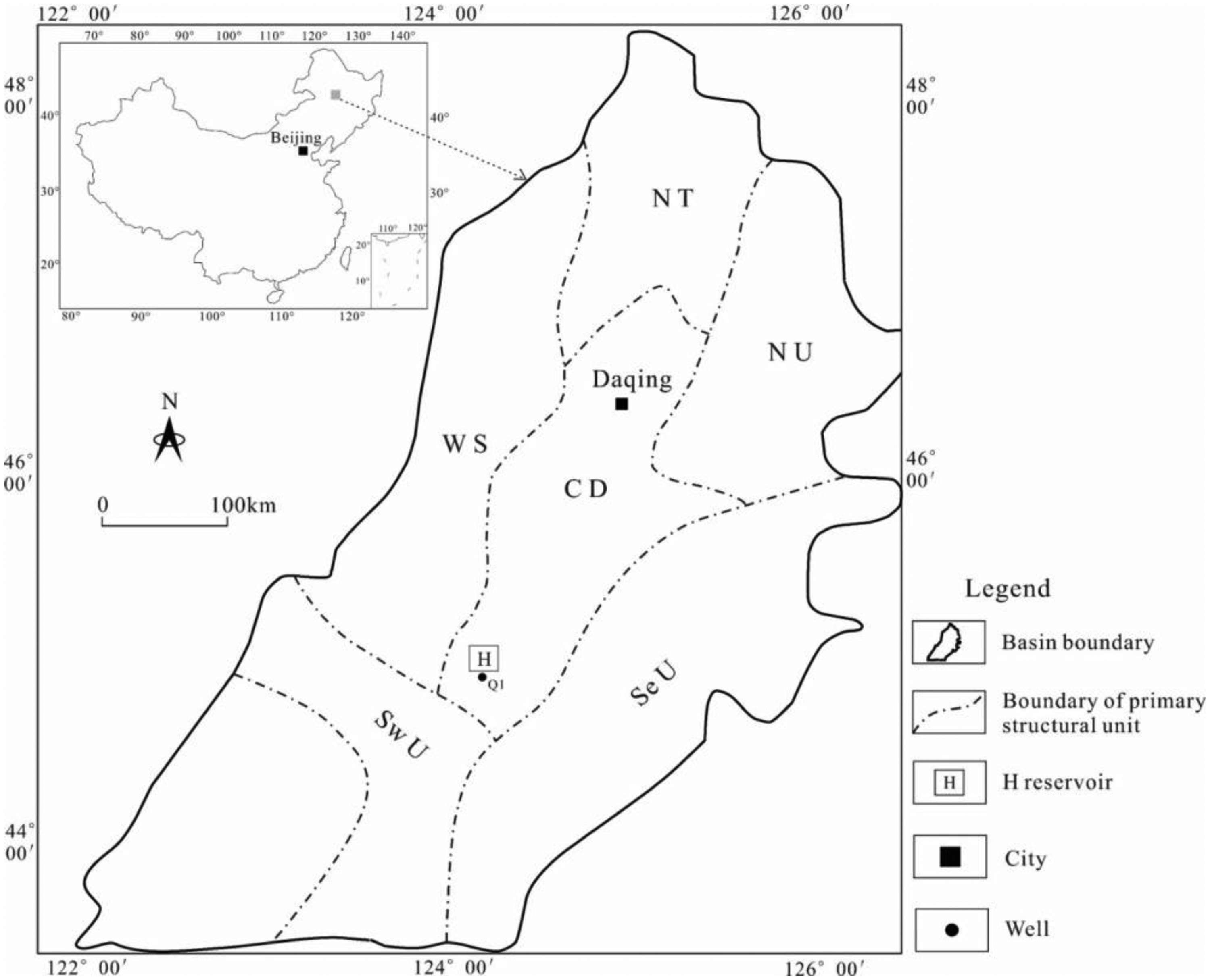
Structure location of the study area. N T: northern terminal; W S: western slope; C D: central depression; Sw U: southwest uplift; Se U: southeast uplift; N U: northeast uplift.
Stratum
The study area received deposits of Late Cretaceous in the Mesozoic and Cenozoic. The Lower Cretaceous can be divided into Qingshankou, Yaojia, Nenjiang, Sifangtai and Mingshui Formations from bottom to top, thickness of which ranges from 1720 m to 2050 m (5643-6726 ft) (Figure 2). The Qingshankou Formation, a main oil-bearing reservoir, can be further divided into Q1, Q2 and Q3 Members from bottom to top (Liu et al., 2004). Q1 Member, as the study target in this paper, ranges from 100 m to 120 m (328-394 ft) in thickness with burial depth of 2300 m to 2500 m (7544-8200 ft), which is dominated by black mudstones, gray siltstones and gray fine sandstones, followed by argillaceous siltstones and silty mudstones. Furthermore, the No.1, No.6 and No.8 layers have large-scale and well-connected sandstones, which are the primary reservoirs in the Q1 Member (Zou et al., 2004).
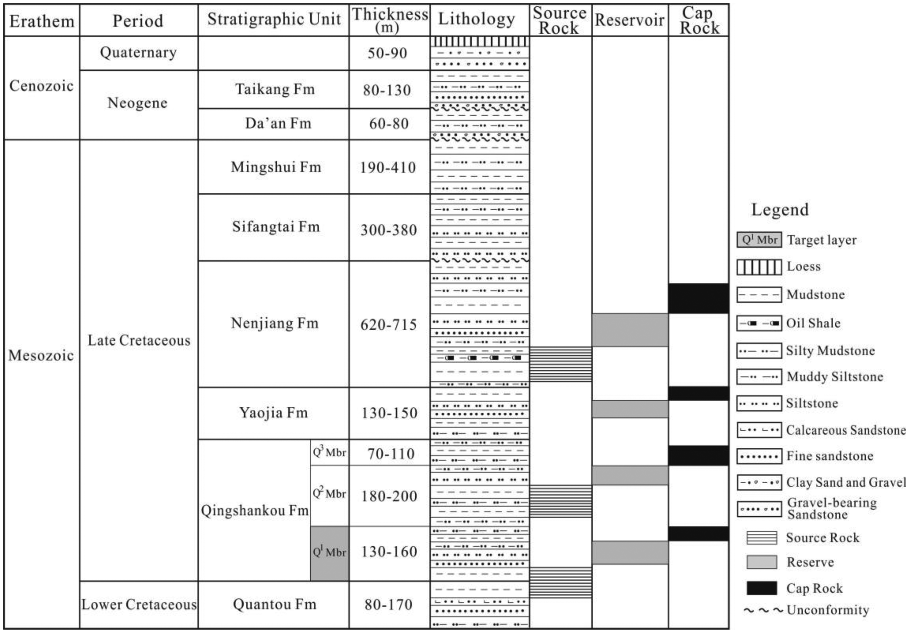
Schematic stratigraphy and source rocks, reservoirs and cap rocks of the study area in the Songliao Basin. Fm = formation, Mbr = member.
Reservoir
The Qingshankou reservoirs of H reservoir in Songliao Basin was essentially deposited in delta front environment with the provenance orientation from the Baokang drainage system in the southwest (Wei et al., 2007). The reservoir is dominated by fine rock fragment feldspathic sandstone, with debris sandstone of secondary importance, specifically, detrital quartz content ranges from 28% to 40%, while detrital feldspar content and rock fragment content are 32% to 44% and 18% to 34%, respectively. The pore system is mainly composed of intergranular pores, followed by residual intergranular pores and dissolution pores. The thickness of single sand body in the primary production layers is in a range of 2.0 m to 4.5 m (6.6-14.8 ft). The physical properties of reservoir near provenance orientation are better than those at the front of the deposition center (Hu et al., 2019). Physical property analysis on core samples shows that reservoir porosity is between 6.2% to 17.1% with average value of 12.8%, and permeability is generally less than 10.0 × 10⁻³ μm2 with average value of 3.6 × 10⁻³ μm2, which is a typical sandstone reservoir with medium porosity and low permeability (Xu et al., 2009). The average oil production of single well is 1.6 t/d with water content of 46.1%, and recovery ratio is only 4.1% in test well groups without CO2 injection.
Methods and materials
The lithology and natural fractures were described by using core samples from 3 wells with total length of 316 m (1036 ft). Physical property and natural fractures were interpreted using log data. Oil displacement efficiency were also analyzed by using CO2 injection monitoring data from 3 wells, dynamic data from 16 wells and another geological data.
Sand body identification
The lithology can be identified by referring to the shape of spontaneous potential (SP) curve, e.g., the typical sand body in the sandstone-mudstone section can be indicated by obvious SP anomaly (Zhou et al., 2008). Natural radioactivity in rocks measured by Gamma-ray (GR) log can be strengthened with increasing shale content in sedimentary rocks (Liu et al., 2015). Therefore, GR log can be used to calculate shale content when only radioactive argillaceous occurs. GR curve after environment correction can be used to identify sandstone by referring to the core description. Shale content can be determined using following equations (Hou et al., 1996; Myers and Bristow, 1989)
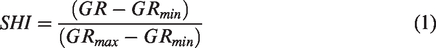
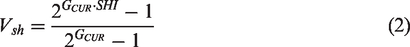
Where SHI is shale content index, Vsh is bulk volume fraction of shale, GR reading of mudstone baseline is recorded as GRmax when Vsh is 100%, GR reading is recorded as GRmin when Vsh is 0%, GCUR is an empirical GR constant fitted by core data.
The contact and connection of single sand bodies can be studied based on sedimentary microfacies and dynamic data (Lu et al., 1999), which can refer to the sedimentary cycle in same layers from adjacent wells. It is also necessary to compare the height difference and thickness difference of single sand bodies in the same layers (Jin et al., 2010).
Description method of natural fracture
Natural fractures are described based on core observation and imaging log interpretation in this study. Core observation is the most effective way to identify subsurface natural fractures (Nelson, 2001; Zeng, 2004), which is mainly used to describe macro natural fractures, e.g., occurrence, intensity and location. Core orientation, a key to judge natural fracture strike, can be ascertained using paleomagnetic orientation method (Gong et al., 2019; Pinto and McWilliams, 1990). Imaging log interpretation is another effective method to identify and evaluate natural fracture parameters (Luthi and Souhaite, 1990), where occurrence and property of natural fractures can be analyzed using line pattern and shape from imaging log (Paillet, 1993; Prioul et al., 2007).
High-permeability zone identification
High-permeability zone in the sandstone reservoirs can be classified into two different ones e.g., the primary one and the secondary one (Li et al., 2005), while the former one with matrix permeability significantly higher than the average value is the target in this paper. They are identified by using acoustic velocity (AC) log permeability interpretation and dynamic data analysis, before which log data standardization was carried out (Xiong et al., 1991). The permeability logging interpretation model was established using cross-plot method (Figure 3), which was corrected with core physical property measurement using the steady-state method (Li et al., 2015). The result is reliable when the permeability difference between core measurement and AC log interpretation is < ±12%. The permeability log interpretation model was used to identify high-permeability zone. In addition, gas velocity in high-permeability zones is several times higher than that in low-permeability zones, resulting in gas breakthrough (Manrique et al., 2013).
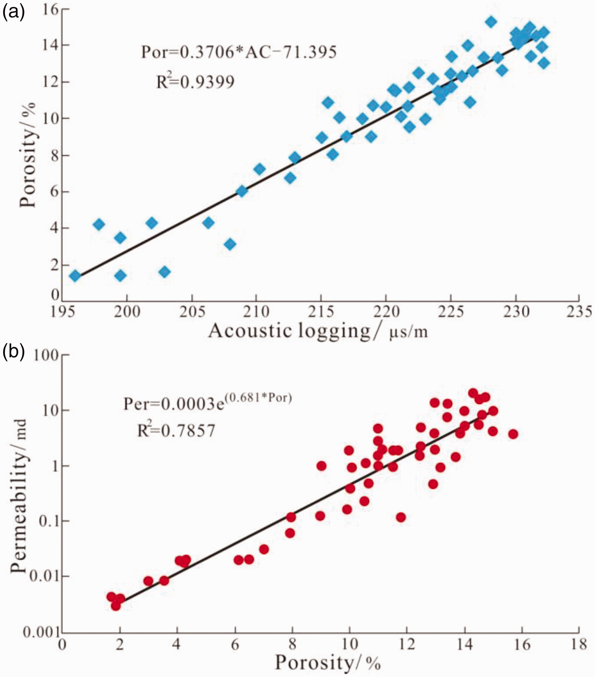
Interpretation model of porosity and permeability in the Q1 sandstone. Por=porosity, Per=permeability. (a) Relation between porosity and acoustic logging. (b) Relation between permeability and porosity.
CO2 injection
General CO2 injection and miscible flooding were adopted in the study area. Three gas injection wells with abundant dynamic monitoring and geological data are employed as study examples, including G1, G2 and G3 well groups with three injectors and 13 producers (Figure 4). The well pattern was inverted seven-spot CO2 injection, that is, a gas injection well group had one injector and six producers. The CO2 injection pressure was about 12 MPa with average CO2 injection volume of 30 t/d in a single well, while production in oil wells was under relatively stable pressure. Perforation intervals were consistent in three gas injection well groups. The CO2 suction volume in different layers was measured using turbine flowmeter method (Tang et al., 2005) with test accuracy of ± 2.0%.
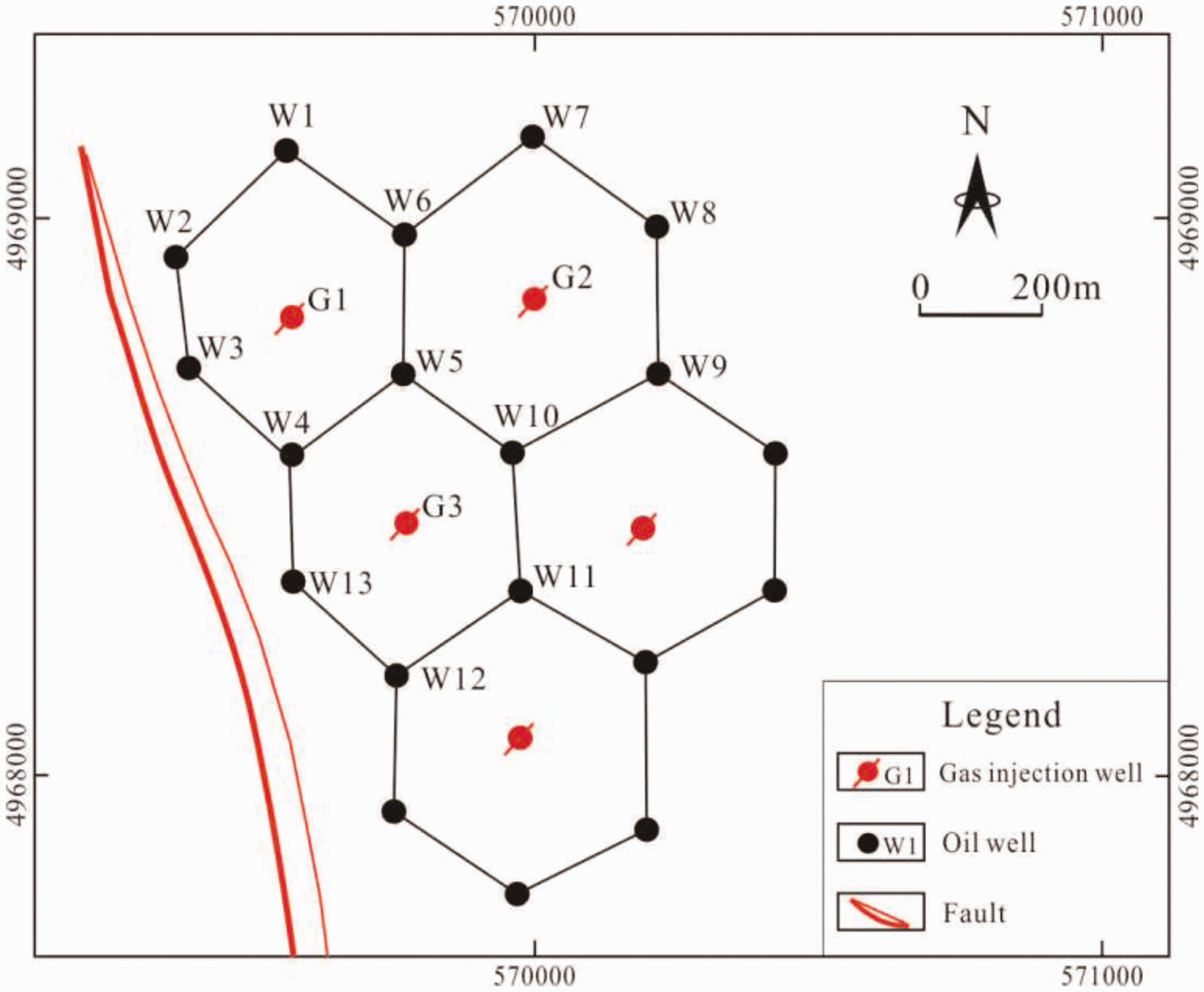
Location of gas injection well groups.
Results and discussion
Sand body
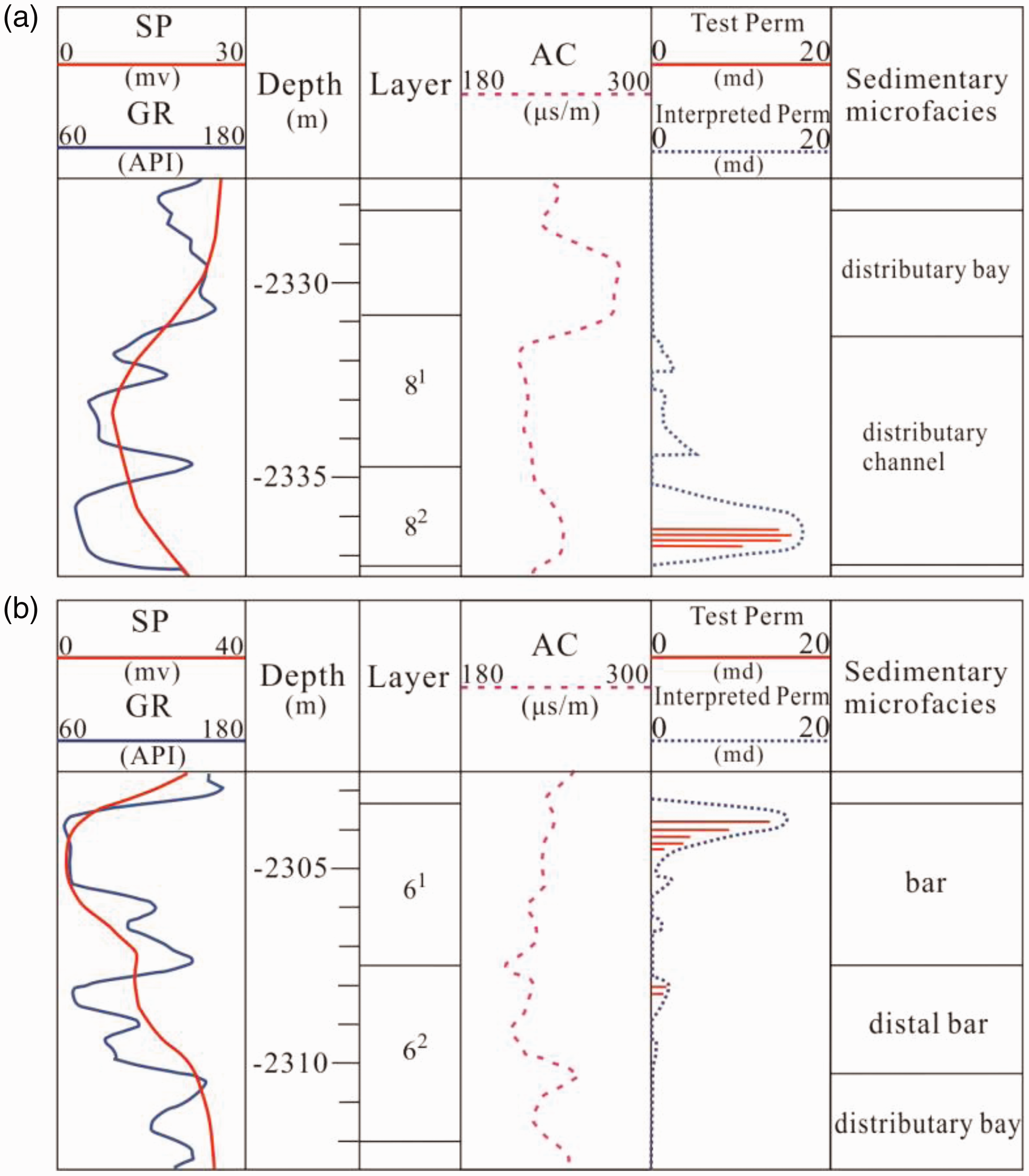
The sand body can be categorized into two microfacies: subaquatic distributary channel and mouth bar, which are assumed to be strip-shaped and sheet-shaped, respectively. Mouth bar is composed of thick bar body and thin bar edge. The large-scale sand bodies were deposited in the northwest (NW) of the H reservoir. Vertically, thick sand bodies are distributed in No.1, No.6 and No.8 units of the Q1 Member. The subaquatic distributary channel and mouth bar sand bodies are widely contacted with each other, while dynamic data exhibits that the distributary channel and bar body are well-connected, and distributary channel and bar edge are moderately-connected (Figure 5(a)). The sand bodies in mouth bar are contacted in three patterns, specifically, bar bodies are well-connected, followed by bar body and bar edge, while the bar edges are poorly-connected (Figure 5(b)). The sand bodies in subaquatic distributary channel are also contacted in three patterns. The superimposed sand bodies are well-connected, but occurs locally, while separated sand bodies have poor connection (Figure 5(c)).
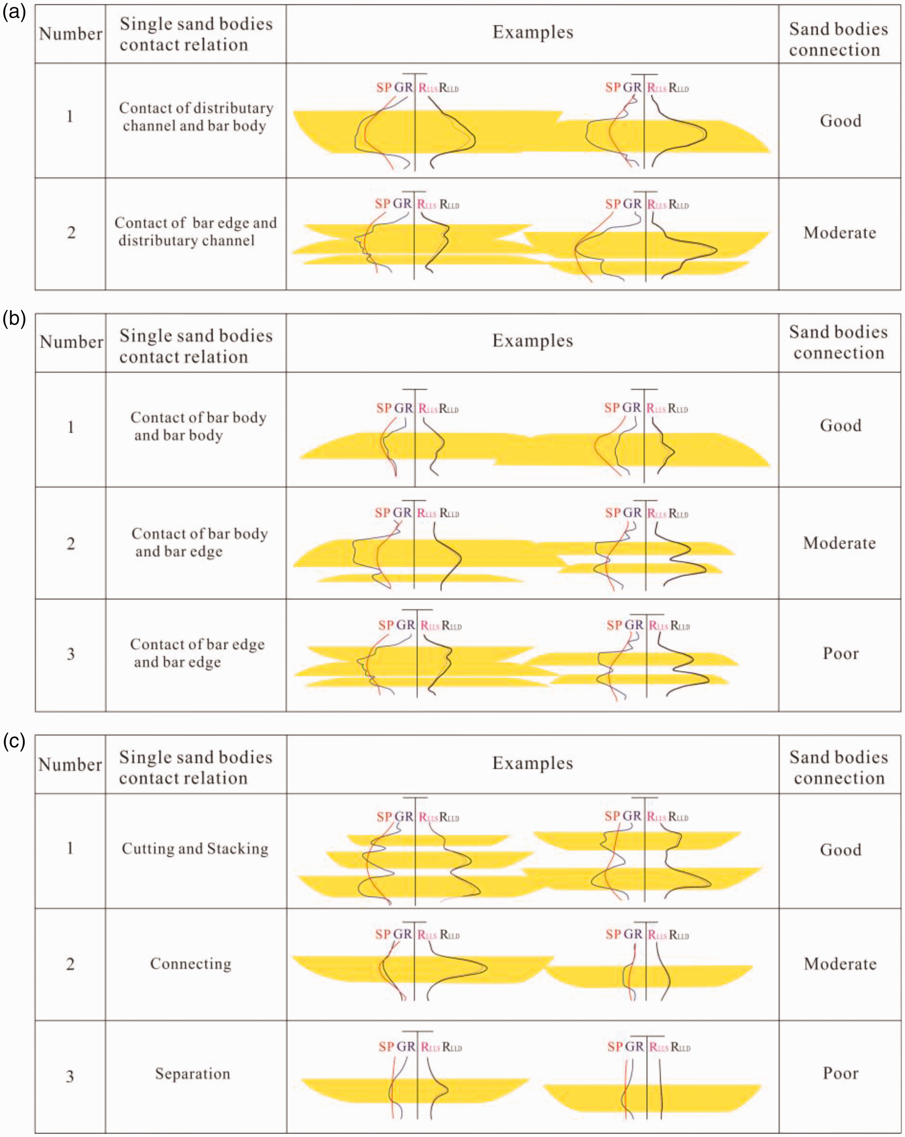
Superposition and connection patterns of sand bodies. (a) Connected channel and mouth bar sand bodies. (b) Connected mouth bar sand bodies. (c) Connected channel sand bodies.
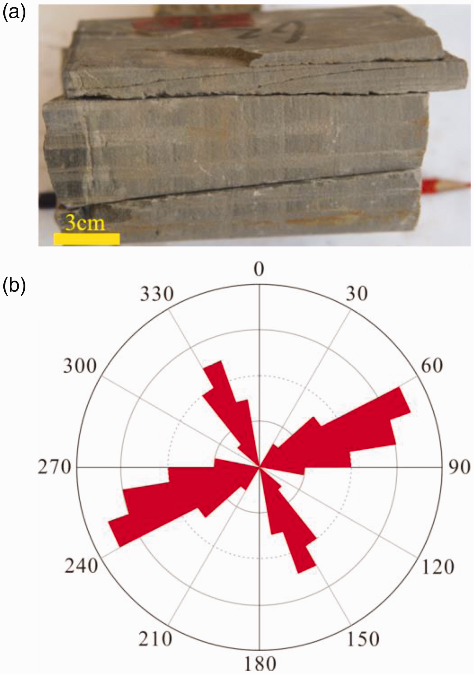
Natural fracture
Two types of fractures are present in the study area: tectonic fracture and diagenetic fracture. Shear fracture is the primary one due to tectonic compression, which are commonly vertical or high dip-angle to the bedding planes. They mainly occur in groups in siltstones and fine sandstones with straight and smooth surfaces and obvious directions (Figure 6(a)). Diagenetic fractures are mainly grew in argillaceous with small density and low dip-angle to the horizontal. The diagenetic fractures are generally closed with low permeability because of overburden, which has a little contribution to the reservoir development (Gu et al., 2020; Hou et al., 2019; Zeng and Li, 2009). Natural fractures are primarily near NEE-SWW strike, with NW-SE strike ones of secondary importance (Figure 6(b)). The natural fracture intensity has strong heterogeneity in vertical, e.g., it is the highest in the No.1 and No.6 layers with value of 1.6 m−1. Also, in lateral, it is the highest near the boundary fault compared with other positions.
High-permeability zone
The high-permeability zone can be defined with following standard based on geological and dynamic data in the study area, e.g., permeability higher or equal to 10 × 10−3 μm2 and reservoir thickness less than 10%. The high-permeability zone in low-permeability reservoirs may be contributed by differential deposition (Hamed et al., 2015; Hamlin et al., 1996). The high-permeability zones are vertically distributed at the bottom of subaquatic distributary channel sand bodies and at the top of mouth bar sand bodies (Figure 7), and laterally distributed along the distributary channel sand bodies with a few of them in the mouth bar sand bodies in strip shape and bird-feet shape.
Locations of high-permeability zones in different microfacies. Well G3. See Figure 3 for well locations. (a) Locations of high-permeability zones in distributary channel microfacies. (b) Locations of high-permeability zones in distributary mouth-bar microfacies.
Dynamic results of CO2 injection
The production performance of oil wells can be divided into four types after two months of gas injection in No.1, No.6 and No.8 layers. The type I including three oil wells (W2, W3 and W4) has obvious CO2 breakthrough and rapidly production CO2, the type II including W1, W8 and W10 has increased oil production that can last for long period (Figure 8), the type III including W5, W6, W7 and W11 has a small increase in oil output compared with that of water injection, the type IV including W9, W12 and W13 has no fluid production.
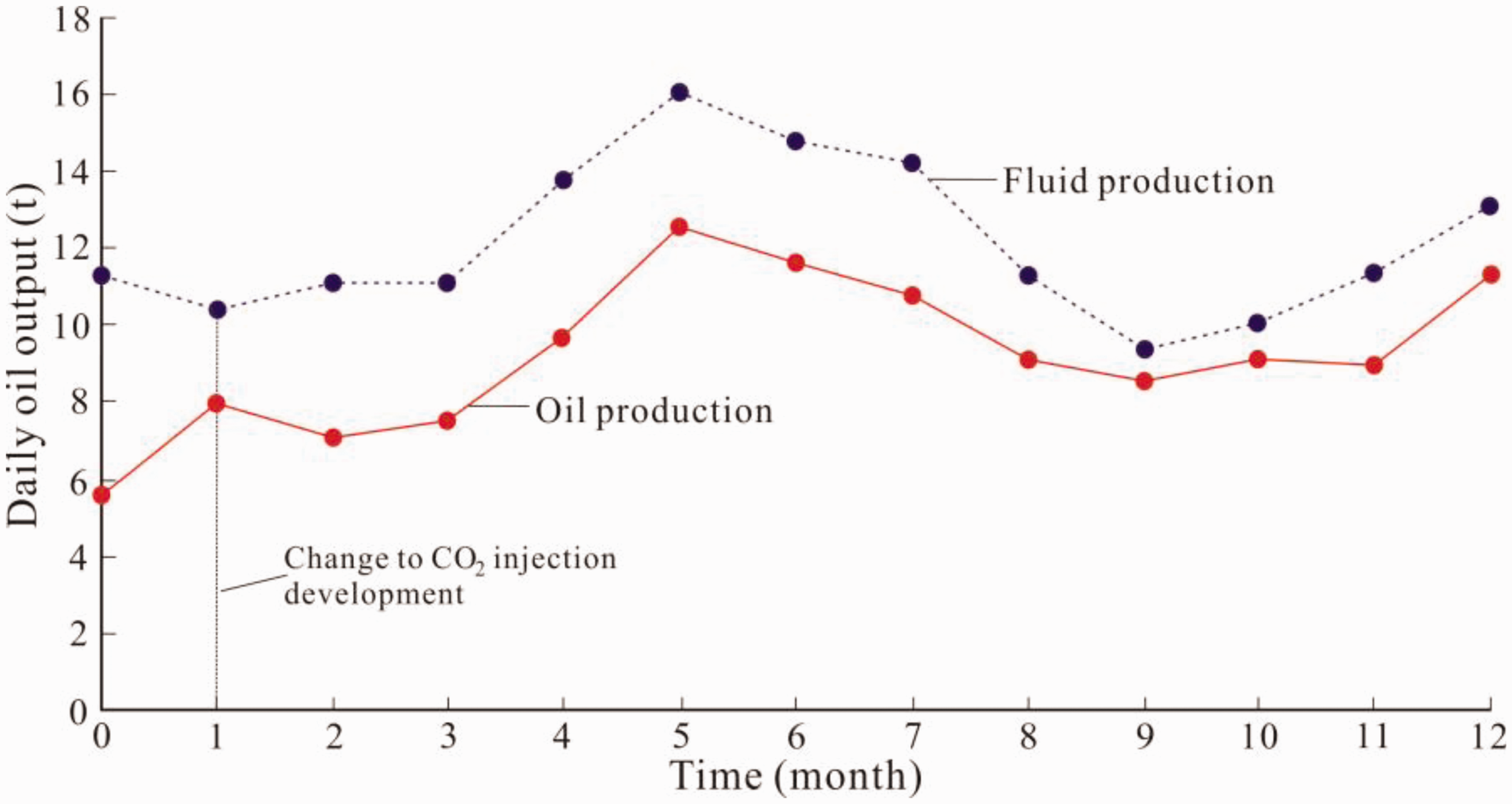
Production graph of Q1 member in the well W10. See Figure 4 for well location.
Key geological factors
Sand body size is obviously controlled by sedimentary facies (Fabuel et al., 2009; Miall and Arush, 2001), e.g., sand bodies of subaquatic distributary channel microfacies and mouth bar microfacies are distributed in large scale in the study area. The Type I wells and gas injection wells are laterally well-connected by the joined distributary channel and mouth bar sand bodies (Figure 5(a)1) and joined mouth bar sand bodies (Figure 5(b)1). Good connectivity between sand bodies provides an important pathway for CO2 flooding in low-permeability reservoirs. Natural fractures can be found in the sand bodies between Type I wells and gas injection wells, which can provide dominant seepage channels for low-permeability reservoirs (Laubach et al., 2018; Tamagawa and Pollard, 2008). Natural fracture intensity is high in large-scale sand body in northwest of CO2 injection test area, which is close to the boundary fault, confirming that fracture growth is controlled by rock mechanical property and structure location (Chad et al., 2003; Narr and Suppe, 1991). Natural fractures are primarily NEE-SWW and NW-SE strikes in the study area, which is easily to cause CO2 breakthrough along these directions in current well pattern. High-permeability zones can also become primary channels for gas flowing during the CO2 injection (Dou et al., 2001). However, it can only improve the connection of contemporaneous deposits with same facies (Li et al., 2005). Most Type I wells in the early stage of CO2 injection are distributed in the northwest of the study area, which are closely related to the good connection of sand bodies, higher intensity of natural fractures and the occurrence of high-permeability zones (Table 1).
Geological characteristics of CO2 injection wells and oil wells.
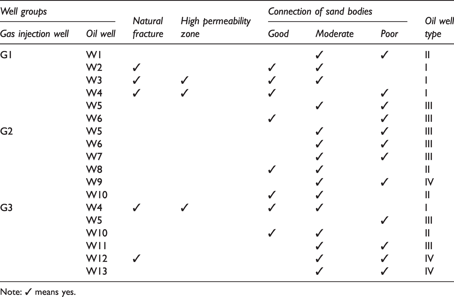
Note: ✓ means yes.
Sand bodies is well or generally-connected in Type II wells without natural fracture or high-permeability zone. In some cases, although natural fractures can be found in sand bodies, they are commonly poorly-connected and are in small-scale. All these are beneficial to improve the CO2 flooding efficiency (Abdul et al., 2013; Diao et al., 2020; Wei et al., 2019). For example, the sand bodies in No. 1 layer in well G2 and well W8, which are derived from the same channel microfacies with good connection (Figure 9), are not affected by the primary seepage channels in other directions. Consequently, the injected CO2 from well G2 can evenly advance along sand bodies, which enhances oil displacement efficiency in well W8.
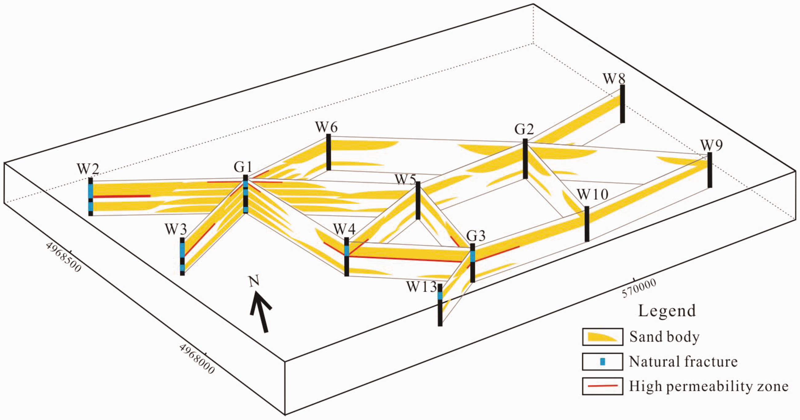
Fence diagram of sand bodies, natural fractures and high permeability zones in no.1 layer in some well groups.
In terms of type III wells, the sand bodies are generally or poorly connected with low fracture density or even no fracture growth. Natural fractures or high-permeability zones with good connection occurs between other oil wells and CO2 injection well, which makes the injected CO2 break through along fractures or high-permeability zones, resulting in obvious fingering phenomenon (Lin et al., 2010; Simeon et al., 2016). Therefore, these wells have low oil displacement efficiency compared with Type II wells. For example, W5 is an oil well receiving gas from G3. No.1 layer in well W5 is generally connected with well G3. Unfortunately, natural fractures and high-permeability zones occur in the same sand body between well G3 and well W4 (Figure 9). Consequently, CO2 advances along the natural fractures and high-permeability zones, resulting in a low oil displacement efficiency in W5 well.
Sand body in Type IV wells is poorly-connected, e.g., sand bodies in No.1 layer between well G2 and well W9 (Figure 8). Although some sand bodies between CO2 injection well and Type IV wells are generally connected, the dominant seepage channels (natural fractures and (or) high-permeability zones) occur in sand bodies between CO2 injection wells and other oil wells. As a result, gas primarily flows into these wells along the dominant seepage channel (Li, 2018).
The dynamic performance and geological data in different well groups suggest that the coupling of sand body connection, natural fracture and high-permeability zone is the key geological factor to control oil displacement efficiency of CO2 injection in low-permeability reservoir. Among them, the connection of sand body is an important foundation for enhancing oil recovery by CO2 flooding. Certain nature fracture intensity can increase the contact area available for diffusion between CO2 and crude oil in matrix, and enhance CO2 flooding efficiency (Ghasemi and Suicmez, 2019). However, it is easy to form a high-quality pathways under high intensity of nature fracture (Wang et al., 2020). Natural fractures and high-permeability zones generally determine the direction and sweep volume of CO2 flooding (Simeon et al., 2016). Sand bodies of good or moderate connection without natural fractures or high-permeability zones are beneficial to improve the CO2 flooding efficiency, since obvious gas breakthrough easily occurs in oil wells with natural fracture or (and) high permeability zones. Therefore, establishing precise three-dimensional geological model of heterogeneous reservoir with facies based single sand body is essential to describe the complexity of geological systems (Hoffman and Narr, 2012; Wu and Li, 2007). It is of great significance for guiding the CO2 injection scheme design in low-permeability reservoir through emphasizing the distribution of single sand bodies of different microfacies and highlighting the contact and connection of single sand body of different genesis, three-dimensional distribution of natural fracture and high-permeability zone as well as their spatial coupling pattern.
Conclusions
In this study, the H reservoir in Songliao Basin, China, was took as an example to investigate the key geological factors controlling oil displacement efficiency of CO2 injection. According to the research, the following conclusions can be drawn: (1) The coupling of sand body connection, natural fracture and high permeability zone is the key geological factor controlling oil displacement efficiency of CO2 injection in low-permeability reservoirs. Among them, the sand body connection between injectors and producers is the most important controller for CO2 flooding. (2) Sand bodies of good or moderate connection without natural fractures or high-permeability zones are beneficial to improve the CO2 flooding efficiency, since obvious gas breakthrough easily occurs in oil wells with natural fracture zones or (and) high permeability zones in the same sand bodies. (3) Geological analysis should focus on spatial distribution, contact and connection of single sand bodies from different origins, natural fractures and high-permeability zones, and establish precise three-dimensional geological model of heterogeneous reservoir with facies-based single sand bodies, which is of great significance to CO2 injection scheme design in low-permeability reservoirs.
Footnotes
Declaration of conflicting interests
The author(s) declared no potential conflicts of interest with respect to the research, authorship, and/or publication of this article.
Funding
The author(s) disclosed receipt of the following financial support for the research, authorship, and/or publication of this article: This study was financially supported by the National Natural Science Foundation of China (No. 41172015), and by the Foundation of the National Major Science and Technology Projects of China (No. 2017ZX05009001-002).