
Abstract
Hydraulic slotting has become one of the most common technologies adopted to increase permeability in low permeability in coal field seams. There are many factors affecting the rock breaking effects of water jets, among which the impact force cannot be ignored. To study the influencing effects of contact surface shapes on jet flow patterns and impact force, this study carried out experiments involving water jet impingement planes and boreholes under different pressure conditions. The investigations included numerical simulations under solid boundary based on gas–liquid coupling models and indoor experiments under high-speed camera observations. The results indicated that when the water jets impinged on different contact surfaces, obvious reflection flow occurred, and the axial velocity had changed through three stages during the development process. Moreover, the shapes of the contact surfaces, along with the outlet pressure, were found to have impacts on the angles and velocities of the reflected flow. The relevant empirical formulas were summarized according to this study's simulation results. In addition, the flow patterns and shapes of the contact surfaces were observed to have influencing effects on the impact force. An impact force model was established in this study based on the empirical formula, and the model was verified using both the simulation and experimental results. It was confirmed that the proposed model could provide important references for the optimization of the technical parameters water jet systems, which could provide theoretical support for the further intelligent and efficient transformation of coal mine drilling water jet technology.
Keywords
Introduction
Water jet technology refers to a type of method, which utilizes injector and pressure strengthening equipment to provide powerful kinetic energy to process water or other working fluid into high-strength impact fluid (Fan et al., 2019; Tao et al., 2018; Zhang, 2012). The goals include realizing cutting, impact, cleaning, crushing, and other applications (Chu et al., 2016; Sun, 2013). Water jet technology has the characteristics of low temperature, low stress, and high flexibility, and has played an important role in coal, petroleum, chemical industry, shipbuilding, and other industrial fields (Hu et al., 2014; Hutyrova et al., 2016). In the coal industry, the technologies of hydraulic slotting, hydraulic punching, and hydraulic cutting based on water jet applications are the main coal seam permeability enhancement measures currently being adopted and are also research hotspots in the energy field (Aziz et al., 2011; Lu et al., 2011, 2015; Xie et al., 2019; Zhang and Zou, 2018; Zou et al., 2014). In February 2020, the National Development and Reform Commission, the National Energy Administration and other eight ministries and commissions jointly issued the guiding opinions on accelerating the intelligent development of coal mines, which clearly proposed to establish an intelligent coal mine system with intelligent perception, intelligent decision-making and automatic execution. Therefore, the intellectualization of water jet technology should be the focus of future research.
Research studies regarding the processes of water jets impacting coal and rock have always been hot topics in the industry and the breakthrough of intellectualization. These research investigations have practical significance for mine gas prevention and control measures (Du et al., 2016; Lei and Dai, 2019; Liao et al., 2013a; Liao et al., 2013b; Ma et al., 2011). Jiang et al. (2018) have shown that the coal around the borehole is mainly damaged by tensile stress and shear stress. The coal-breaking process of hydraulic punching impact load can be divided into two stages: crushing accumulation and rapid crushing. Shen et al. (2015) showed that the coal and rock breaking by large-diameter water jet impact can be divided into three stages: initial response, stability failure, and fracture mutation, and deduced the criterion formula for inducing instability. Lin et al. (2018) have shown that for high-pressure gas–liquid two-phase flow, the damage of coal and rock mass is gas–liquid–solid three-phase coupling, and the alternating action of gas-phase multistage collapse and liquid-phase pulsation impact promotes the initiation and propagation of cracks.
In summarizing the research in this field, this study found that the majority of the research content included theoretical analyses and field experiments. However, due to technical limitations, the majority of the experimental processes had only observed the impinging flow patterns of the water jets on surfaces using the naked eye and available camera technology. It was found to be difficult to observe the flow field distributions inside the water jet, and the measurements of the corresponding results were also found to be challenging. Therefore, the research development was generally slow. However, with the continuous development of computer numerical simulation technology, computer simulations of water jet impact processes can now easily determine the internal flow rates, pressure levels, and other experimental data during the impact processes, and many quantitative analysis and research investigations have successfully carried out. Yang et al. (2019a) used FLUENT to simulate the impact processes of abrasive water jets under submerged states with different environmental velocities and analyzed the changes in the solid–liquid two-phase flow patterns. Zong et al. (2020) carried out a three-dimensional numerical simulation study regarding the impact processes of gas–liquid jets; analyzed the macroparameters of the jet reaction plumes and their variation rules; and investigated the influencing effects of inlet pressure on the temperature distributions of convection fields and the corresponding relationships between the inlet pressure and the gas plumes. Furthermore, some researchers adopted numerical simulation methods to study the influences of geometric and injector parameters on water jet flow fields, and then successfully optimized the injector parameters (Liu et al., 2020; Yang et al., 2019b). The research regarding water jet impinging on surfaces with different shapes has been further deepened with the development of numerical simulation technology. Huang (2015) used high-speed camera methods and image processing technology to analyze the internal impact disturbance laws of water jets with different shapes when impacting plane, concave, convex, and inclined surfaces, and tracked the motion tracks of different fluid particles using numerical simulation methods. The obtained results revealed the mechanism of water hammer pressure.
At the present time, the majority of the researchers examining water jet impingement processes tend to focus on the damage effects and laws of water jet impact force on targets. However, the influencing effects of the contact surface shapes on jet flow fields, and the impacts of the jet flow field characteristics on the impact force have received little attention. In addition, most of the numerical simulations use simple two-dimensional models to study the jet flow fields. This study combined two methods: indoor experiments and numerical simulations. A numerical simulation model of gas–liquid two-phase coupling was first established, and the development and variation laws of water jets in boreholes under different pressure conditions were explored using the numerical simulation results. Then, the simulation results were compared and verified using indoor experiments involving high-speed camera observations. Finally, the influencing effects of the contact surface shapes on the jet flow fields and impact force were revealed. The research conclusion can provide theoretical support for the further intelligent and efficient transformation of coal mine drilling water jet technology.
Numerical simulation model
Geometric model and meshing
To simulate the impact of water jets on contact surfaces, a three-dimensional cubic model was established as the experimental space. The model consisted of two parts: an injector and an impacted contact surface. The injector was cylindrical with a diameter and length of 2 mm. The target distance was set as 300 mm. The impacted surfaces were square planes with side lengths of 500 mm and semi-cylindrical surfaces with radii of 80 mm. Due to the large differences between the diameter of the injector and the sizes of the impacted surfaces, a separate mesh was added to the injector. The details of the geometric model and meshing are shown in Figure 1.
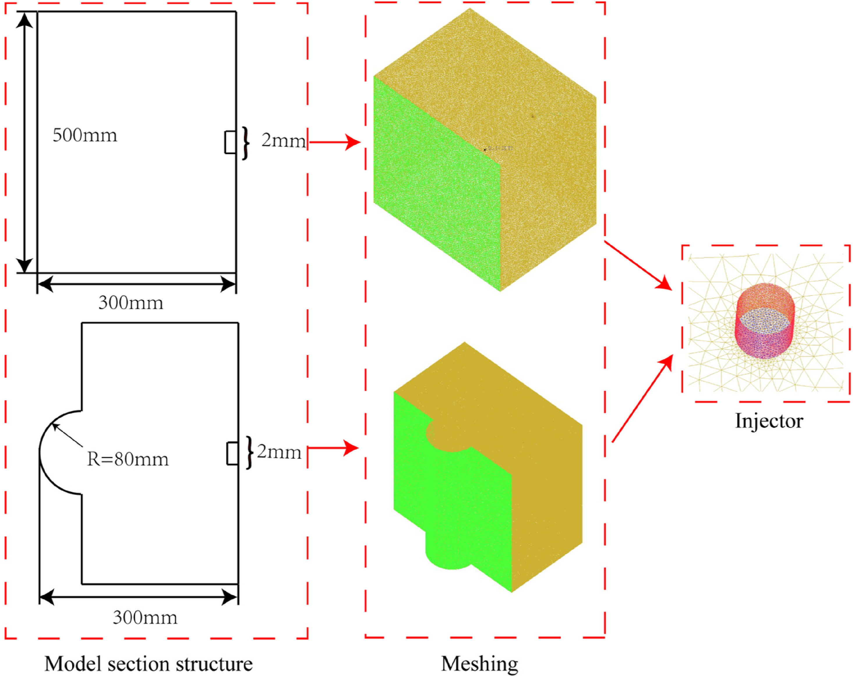
3D geometric model.
To eliminate the influence of mesh accuracy on the simulation results, the model is re-meshed based on the existing number of meshes, and the low-, medium-, and high-mesh models were obtained respectively, which are brought into the solver for calculation. Taking the jet axial velocity as the reference object, the comparison results are shown in Figure 2. It can be found that at 50 mm from the inlet, the calculation results generated by mesh-low and mesh-medium fluctuate in varying degrees in speed. Therefore, mesh-high is used as the standard to mesh the numerical model, and about 380,000 meshes are finally generated, which reduces the influence of mesh accuracy on the calculation results.
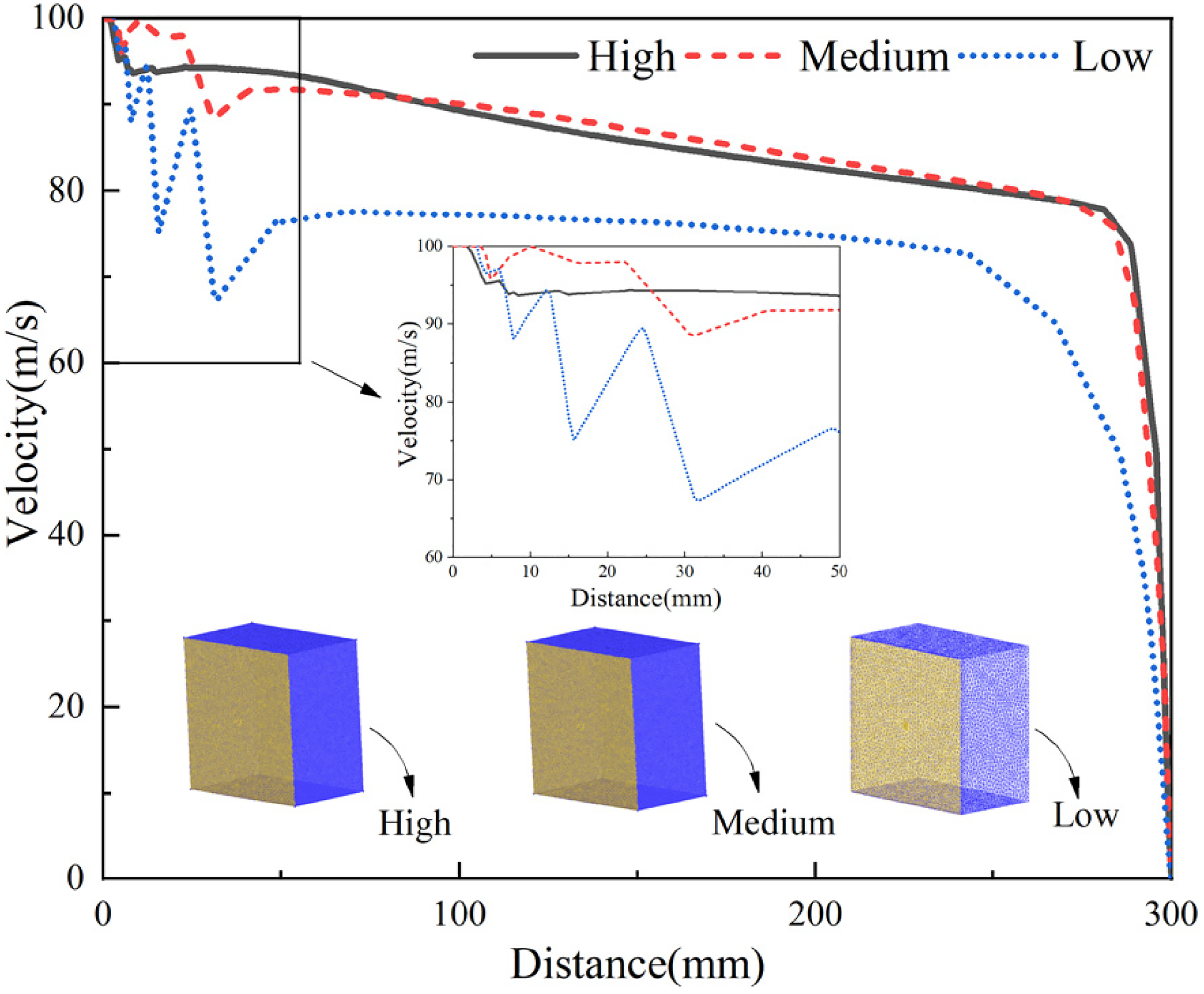
Grid independence analysis.
Governing equation
For commonly used jet ejectors, the water jet process is a millisecond high-speed gas–liquid multiphase steady flow process. Therefore, a standard k-ω model was selected to simulate the turbulence. When the mathematical model was formulated, the following assumption was accepted: All of the fluids were ideal incompressible liquids, and their viscosity, heat conduction, and transverse flow were ignored (quasi-one-dimensional approximations). The governing equation of the standard k-ω model is as follows (Koutsourakis et al., 2012):
Mass conservation equation:

Momentum conservation equation:


Energy conservation equation:

Boundary conditions
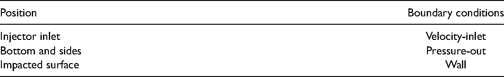
To simulate real jet impingement environmental conditions, the entire simulation area was set as being filled with air and the inner area of the injector was set as being filled with water. The setting of the boundary conditions is shown in Table 1. The jet pressure levels were taken as 2–16 MPa, respectively. In the current study, the flow field characteristics and pressure characteristics of the water jets under different outlet pressure levels were compared.
Boundary conditions.
Simulation results and discussion
As one of the most important parameters in water jet technology, changes in the outlet pressure levels are known to have significant impacts on the flow patterns and impact force of water jets. However, the cutting effects of water jets are often adjusted by changing the outlet pressure levels. Therefore, this study found that by analyzing the variation laws of the flow fields, velocities, and impact force of water jets under different outlet pressure conditions, the interactions among the shapes of the contact surfaces, jet flow fields, and impact force could be further explored.
Effects on the flow fields of different outlet pressure levels
The reflection flow patterns produced by high-pressure water jets impinging on contact surfaces are considered to be types of adhesive jets in confined areas. In accordance with different contact conditions, the water jets will contact the targeted surfaces and reflection jets at certain angles via the fitting jets. Figures 3 and 4 detail the velocity contours of water jets impinging on two types of surfaces under different outlet pressure conditions. It can be seen in the figures that the outlet pressure levels and the impacted surfaces of the jets had influencing effects on the flow fields of the impinging water jets. It was observed that after the water jets were ejected from the injector at high speed, they impacted the contact surfaces and produced obvious reflection fluid. The areas of the counter jets increased with the increases of the outlet pressure. This study compared the simulation results of the two different contact surfaces and found that the reflected flow patterns of the water jets impinging on the curved surface were more stable. When the water jets impinged on the curved surface, the reflected flows appeared as concentrated beams and shot out along the contact surface. However, when impinging on the plane surface, the reflected flow patterns of the water jets diverged in a fan-shaped manner. Along with the bundled reflection flow in the direction of the contact surface, there were also velocity distributions near the cores of the jets. This may be due to the fact that the fluid was more concentrated when the water jet impinged on the surface and the majority of the fluid had been ejected along the contact surface, resulting in the reflected flow beginning to appear when it left the contact surface. It was observed that when impinging on the plane surface, the fluid was splashed around under the impact force, which not only expanded the coverage area of the reflected flow, but also the entrainment effects of the splashed jets and air outside the reflected flow area. This had resulted in two types of velocity, as shown in Figure 3. These results indicated that the shapes of the contact surfaces have influencing effects on the jet flow fields. However, when water jets impinge on boreholes, the flow fields are more concentrated and the fluid does not easily disperse.
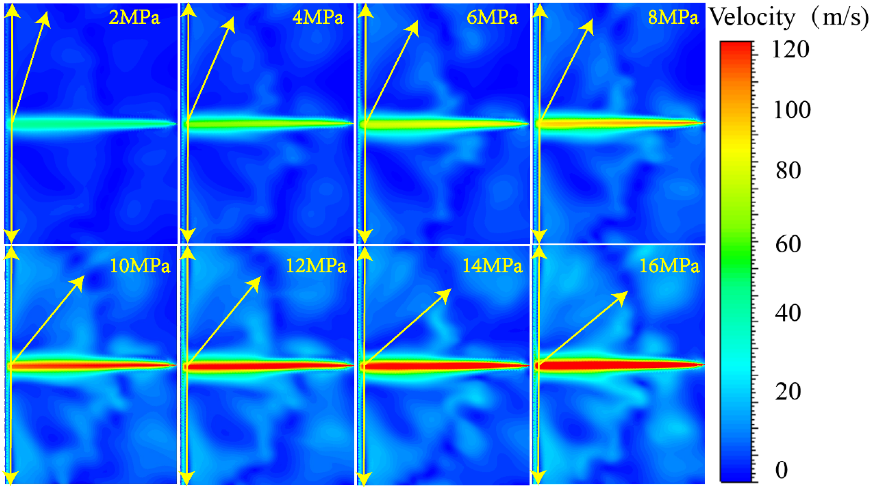
Contour of plane velocity of water jet impingement.
Contour of curved surface velocity of water jet impingement.
To better express the changes in the flow fields using the obtained data, the reflected flow areas were divided by the lines of the same velocity on the velocity contour using post-processing software. The directions and boundaries of the reflected flow are indicated by yellow arrows in Figures 3 and 4, respectively. There were two main boundary lines after the water jets impinged on the contact surface. The first was the attached jet section along the contact surface angle, and the second was the reflected flow section displaying an obvious angle with the fitting jet section. Figure 5 shows the angle distribution of the reflected flow after the water jets impinged on the two contact surfaces under different outlet pressure conditions. It can be seen in the figure that the angle of the reflected flow increased nonlinearly with the change trend of the outlet pressure. The formula of the angle change was obtained by fitting the data with a quadratic function as follows:

Angular distribution of reflected flow on contact surface.
where αp is the reflected flow angle of the impact plane; αc is the reflected flow angle of the impact surface; and P0 is the outlet pressure. The correlation fitting variances R2 were found to be >0.98, which indicated that the fitting results obtained with the function were reliable.
Effects of different outlet pressure levels on the velocity rates
The axial velocities of the water jets represent the kinetic energy contained in the jets, which are also important factors affecting the impact force. The axial velocity data of the two different water jets were derived from the simulations results, and this study's comparison of the changes are shown in Figure 6. It was found that from the injector to the contact surfaces, the development stages could be divided into three distinct stages along the axis direction:
Variation of axial velocity during impact. (A) Plane. (B) Curved surface.
In the present study, it was found that although the two types of water jets had undergone the above-mentioned three stages, the influencing effects of the contact surface shapes on the jet velocity levels could still be determined from the details. When the water jets impinged on the curved surface, the flow fields were more stable and the water jets were more concentrated, which resulted in less fluctuation in the axial velocity levels and the higher speeds within the stable section. In addition, it was determined through this study's data analysis results that the phenomena were embodied. Therefore, by taking the average values of the velocity during the steady flow stage, it was found that the axial velocity levels of the water jets had varied with the outlet pressure, as shown in Figure 7. A data fitting method was used to determine that the variation trends of the axial velocity satisfied the following quadratic function:

Variation of average axial velocity.
where νp is the axial velocity of the water jets impinging on the plane surface; νc is the axial velocity of the water jets impinging on the curved surface; and the correlation fitting variances R2 were all >0.99, which indicated that the fitting results obtained using the function were reliable.
Effects of the outlet pressure levels on the impact force
When the high-speed water jets impinged on the different shaped surfaces, the velocities and directions of the water jets impinging on the contact surfaces had varied due to the different shapes of the various surfaces. That is to say, the kinetic energy of the water jets changed to different degrees (Huang et al., 2019). The changes in the kinetic energy were mainly due to the force levels between the high-speed water flow and the different shaped surfaces. The high-speed jets lost kinetic energy in the original direction and acted on the contact surfaces in the form of impact force. Figure 8 shows a case of high-speed water jets acting on different contact surfaces. It can be seen in the figure that the velocity levels of the reflected flow remained unchanged. In accordance with Newton's second law, the total stress on the contact surface impacted by the water jets was as follows:
Effect of the water jet on different surfaces. (A) Plane. (B) Curved surface.
where ρ is the density of the working liquid, kg/m3; Q represents the flow rate of the water jet, m3/s; ν indicates the velocity of the water jet, m/s; and α is the angle of the reflected flow, deg. Therefore, the total stress of the contact surface can be determined by the water jet velocity, working liquid density, and reflected flow angle.
In actuality, the final impact pressure levels will be different due to the various contact areas where the water jets impinge on different types of surfaces. In this study, taking water jets impacting boreholes as an example, Figure 9 details a cross-section diagram of a certain position in the process of the water jet impact. A two-dimensional coordinate system was established in this study, with the borehole center denoted as the coordinate origin 0; vertical jet direction as the x-axis; and the jet direction as the y-axis.
Cross section of jet impingement curved surface.
In detailed in Figure 9, the radius of the borehole is r; the radius of the water jet section is b; and the radius of the jet section at that position is R. Then, the actual action length L of the jet will be as follows:


In the present study, the above model was verified by the impact pressure levels of the contact surfaces in the simulation results. It was observed that under the different outlet conditions, the impact force of the two types of water jets in the middle range of the contact point was approximately within a normal function distribution, as shown in Figures 10(a) and (b). In addition, it was found to be in a steady state, even after only 300 mm of divergence. The impact force of the water jets, which finally reached the contact center point, was <1% of the outlet pressure. These findings indicated that the kinetic energy loss of the water jets was serious during the impact process, and the impact pressure was higher when the water jets impinged on the curved surface. Therefore, it was indicated that the water jets had retained higher kinetic energy when impacting the curved surface. These results were found to be consistent with the previous research descriptions, and also showed that the shapes of the contact surfaces had impacts on the final impact force. The peak values of the impact force shown in Figures 10(a) and (b) were separately extracted and compared with the calculation results of the model. As shown in Figure 10(c), it was found that the theoretical model proposed in this study had achieved results which were consistent with the simulation results, which verified the rationality of the model.
Variation of impact pressure. (a) Variation of impact plane pressure. (b) Variation of impact curved surface pressure. (c) Comparison of impact peak.
Experimental verification
Experimental system
To verify the rationality of the aforementioned analysis process, indoor experiments similar to the numerical simulation conditions were designed in this study. The experimental system consisted of three subsystems: high-speed camera system; high-pressure liquid supply system; and a water jet generation and regulation system. Table 2 shows the working parameters of each equipment.
Experimental system structure and working parameters.
Figure 11 is the flow chart of this study's experiment. The experimental scheme was divided into two parts, as shown in Table 3.
Flow chart of experiment.
Experimental scheme.
Sample preparation
In the experimental design, the preparation of the samples was also considered to be an important part. For example, whether or not a sample could reach the mechanical properties of coal was a key point in the preparation process. Experimental samples were designed as the impacted targets, as shown in Figure 12. The specimens were 100 × 100 × 100 mm cube standard test molds. To simulate the strength of coal and rock, the samples were constructed from pulverized coal, cement, gypsum, additives, and water. Two strain gauges were set on the top and side, respectively, in order to record the stress changes during the impact process. The structures of the formed sample and target are shown in Figure 12.
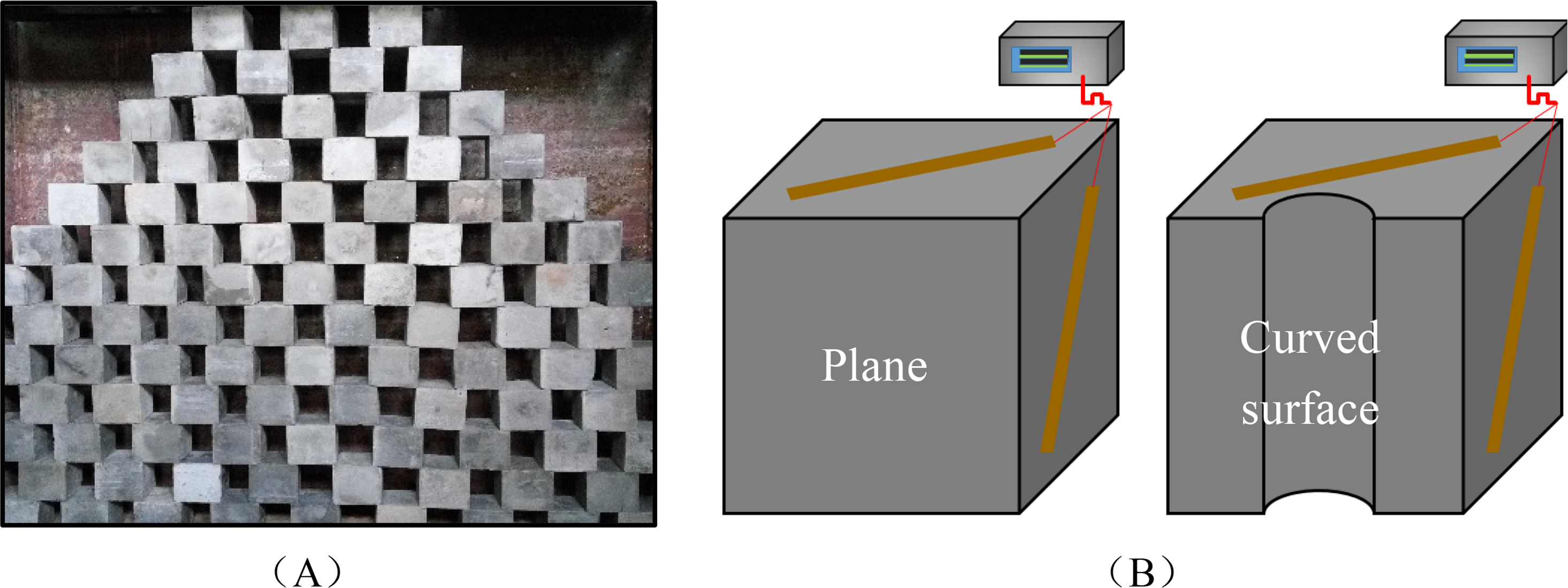
Impact sample. (A) Forming sample. (B) Sample structure.
Experimental results
The first part of the experimental results included a comparison of the flow patterns captured by the indoor experiments with the velocity contours of the numerical simulations for the purpose of verifying the rationality of the numerical model. The instantaneous flow patterns of the water jets impinging on two types of contact surfaces were photographed using a high-speed camera, as shown in Figure 13. It was found that the experimental results were the same as the simulation results. This agreement confirmed that the numerical simulation results matched the experimental results. Following the image processing of the instantaneous flow patterns, the reflected flow angle data of the two different contact surfaces were also generated. These were then compared with the data shown in Figure 5, and the comparison results are detailed in Figure 14. The trends of the experimental results and the simulation results were observed to be generally consistent. Since the velocity distribution in the simulation results could be observed in more detail, the angle of the measured reflected flow section was also higher than that of the experimental results. This study's comparison between the two successfully verified the rationality of the numerical simulations.
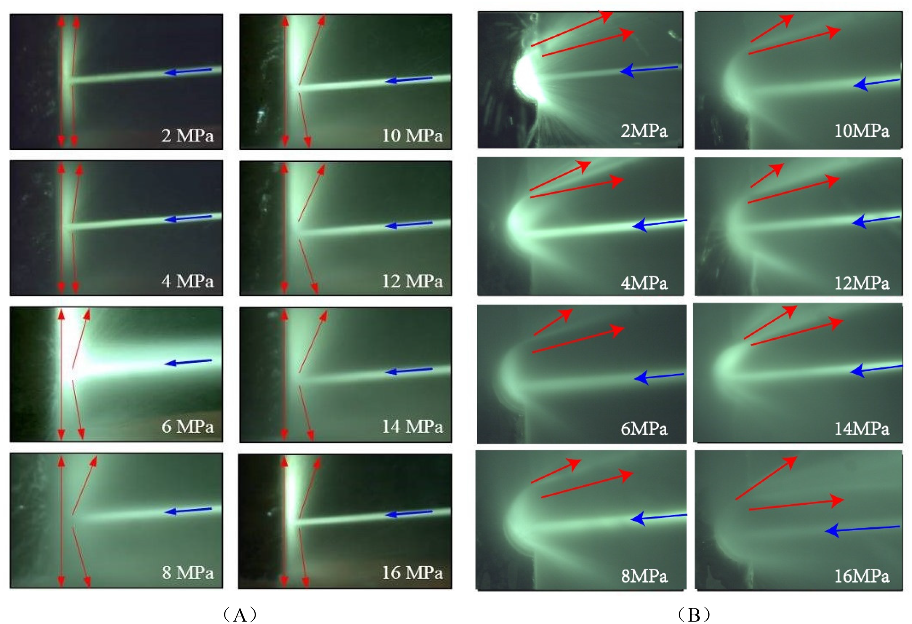
Instantaneous flow state under impinging. (A) Plane. (B) Curved surface.
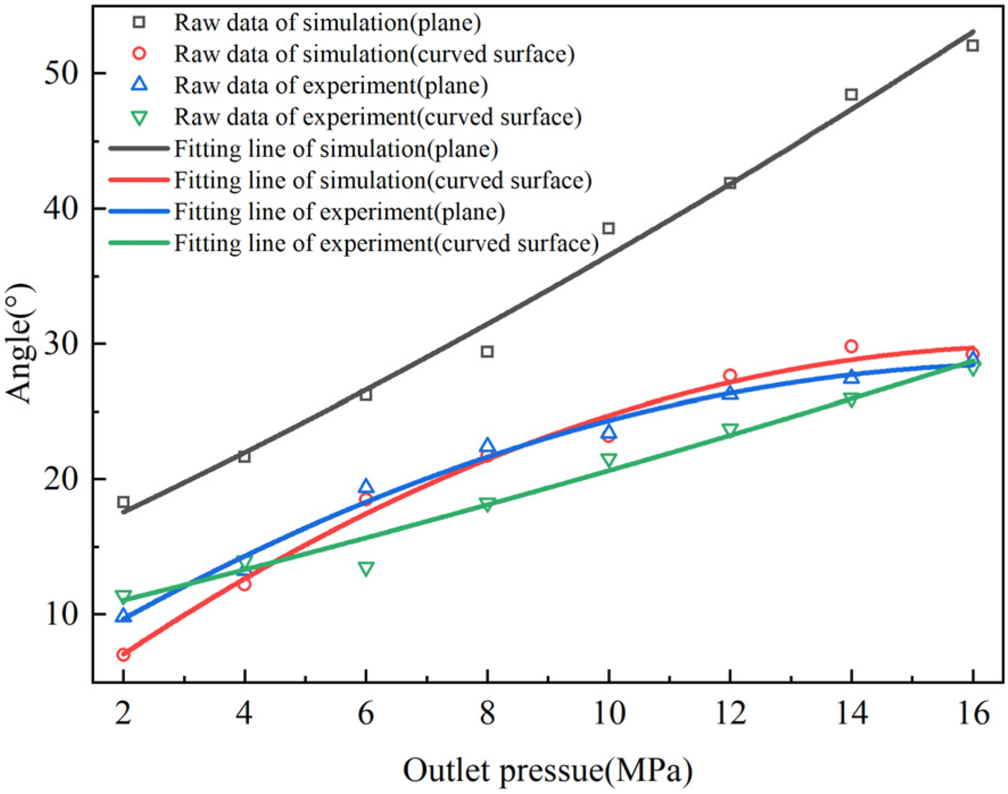
Reflection flow comparison.
The second part of the experimental results mainly involved the verification of the rationality of the theoretical model detailed in the section “Effects of the outlet pressure levels on the impact force”. The crushing degrees of coal and rock were the most obvious factors reflecting the impact force of the water jets. Following the impact tests, the samples were removed from the test bench to observe the surface fracture situations one by one, and the fracture areas of the two surfaces under different outlet pressure conditions were measured. The results of this study's comparison are shown in Figure 15. It was found that under the same impact duration conditions, the broken areas of the borehole sample were larger, indicating that the impact force of the water jets was stronger and the action range was wider. However, it was observed that the experimental results were different when the outlet pressure was 14 MPa. This may have been attributed to sample preparation problems, since the inhomogeneity of the material and the strength of the sample used in that experiment were lower than the others. However, this had not affected the overall trend, and this part of the results successfully verified the rationality of the model, thereby corresponding to the verification results of the numerical simulations.
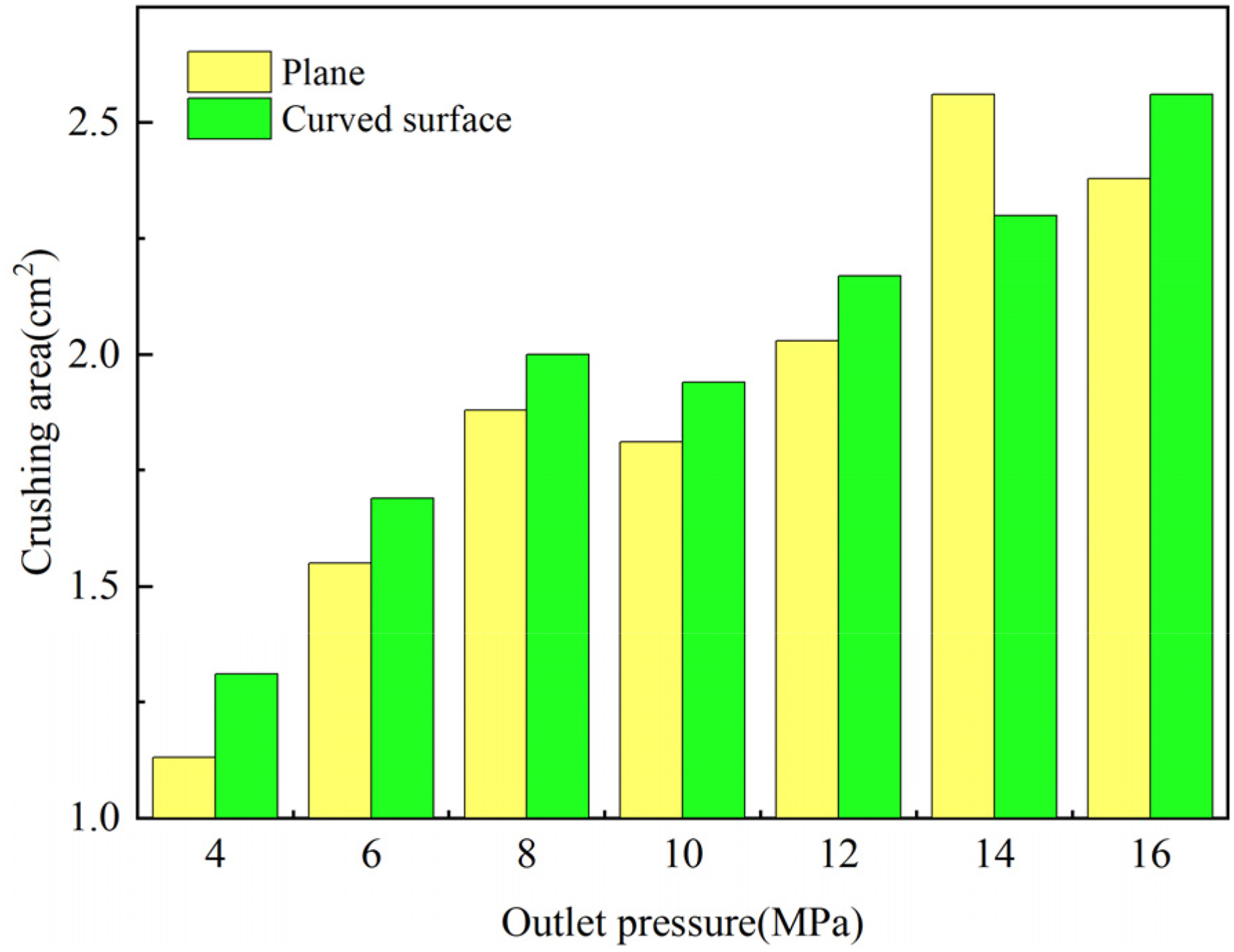
Comparison of crushing area.
Since the existing experimental conditions could not directly measure the impact force on the sample surfaces, a second experimental scheme was adopted to verify the simulation results using the stress changes which were observed during the coal and rock fracturing processes. The maximum outlet pressure of 16 MPa was used to continuously impact the two types of surfaces until the specimens underwent cracking. The stress changes during the impact processes were recorded using a strain gauge device. The results of this study's comparison are shown in Figure 16. The strain levels on the tops and sides of the samples changed with the impact duration, with sudden changes occurring at the moment of fracture. The time required for the water jets to impact the borehole samples to cause fracturing was determined to be approximately half of that from the impacted plane sample to fracture, which indicated that the impact force of the water jets had reached the failure threshold earlier. When the water jets impinged on the plane specimen, the top and side strain levels first increased and then decreased. This was mainly related to the transition from water hammer pressure to stagnation pressure (Huang et al., 2014). When the water jets impacted the surface, the damage threshold was reached during the water hammer pressure stage, and the specimen was directly cracked. These results also verified the rationality of the proposed force model.
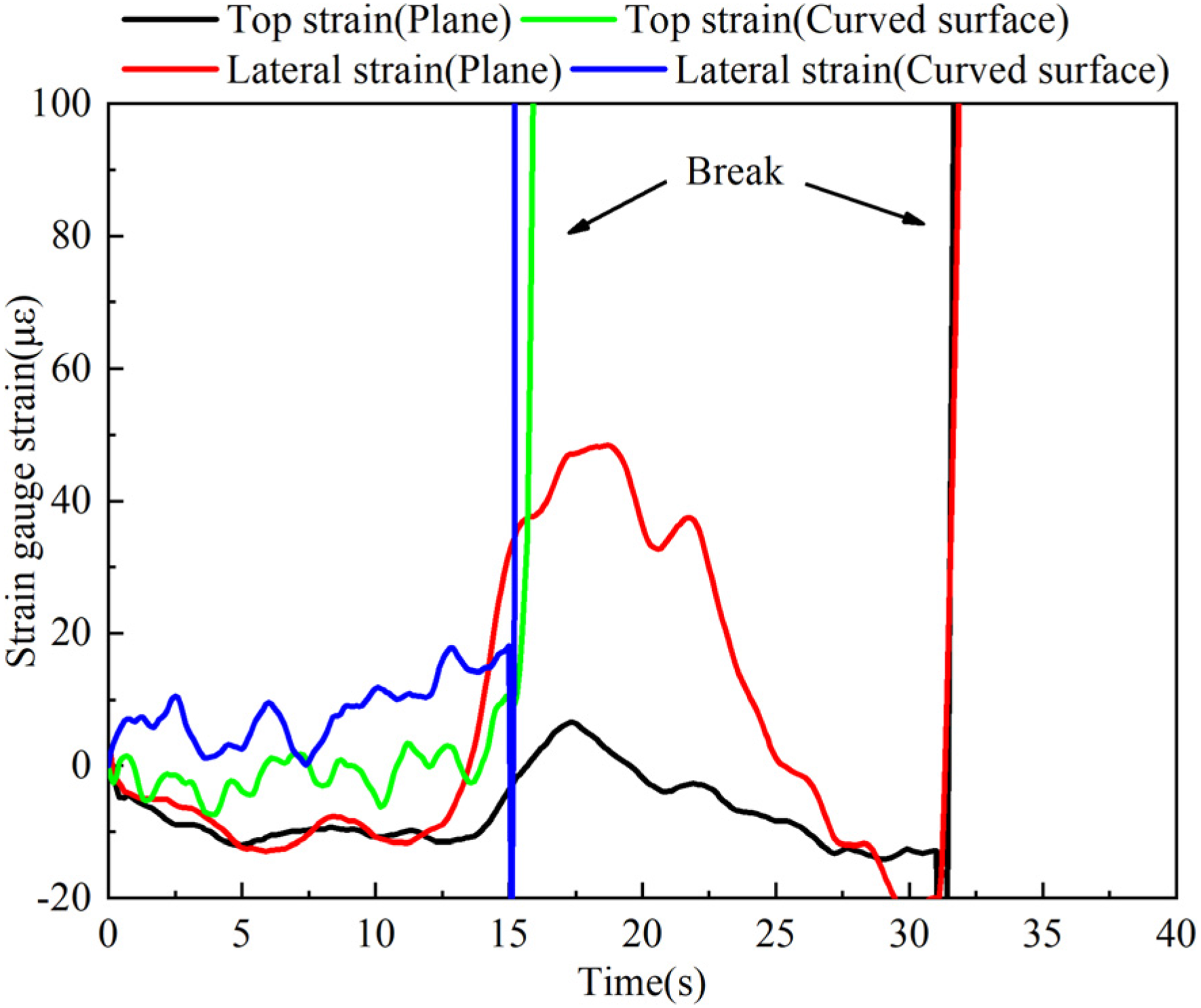
Comparison of strain variation.
Conclusions
The following conclusions were reached in this study:
When water jets impinge on different types of contact surfaces, they will produce reflected flow. The axial velocity will go through three stages of Turbulent, Stable, and Impact with the development of the water jets along with the changes in the distances from the outlet pressure. However, the shapes of the contact surfaces will have certain influencing effects on the angles and velocity rates of the reflected flow. It was found that when water jets impinged on boreholes, the reflected flow distributions were relatively concentrated, and the axial velocity rates were relatively higher and more stable. It was observed that with the increases in outlet pressure, the axial velocity rates of the water jets had risen. The boundaries of the basic section accelerated the diffusion, and the angles of the reflected flow sections generated by the impacts on the contact surfaces increased. Therefore, according to the numerical simulation data, an empirical formula of the angular distributions of the reflected flow, as well as the variations of the axial velocity with the outlet pressure, could be summarized. The impact processes of the water jets were found to be not only related to the water jet velocity levels, working liquid densities, and other factors, but also to the angles of the reflected flow leaving the surfaces and the axial velocity levels. Therefore, based on an empirical formula, an impact force model of the water jets acting on boreholes and plane surfaces was deduced, and the rationality of the model was verified by the simulation and experimental results. In future research, it should be the focus to further clarify the interaction among reflection angle, exit velocity, and exit distance. The mathematical model could be combined with coal rock breaking theory and provide theoretical support for the intelligent and efficient transformation of coal mine drilling water jet technology.
Footnotes
Declaration of conflicting interests
The authors declared no potential conflicts of interest with respect to the research, authorship, and/or publication of this article.
Funding
The author(s) disclosed receipt of the following financial support for the research, authorship, and/or publication of this article: This work was supported by the Cultivation Plan for Youth Researchers of Higher Education Institutions in Shanxi (jyt20190003) and Project 51804212 supported by National Natural Science Foundation of China.