
Abstract
The tight sandstone oil reservoirs characterized by the low porosity and permeability must be hydraulically fractured to obtain the commercial production. Nevertheless, the post-fracturing production of tight oil reservoirs is not always satisfactory. The influence mechanism of various factors on the fracture propagation in the tight oil reservoirs needs further investigation to provide an optimized fracturing plan, obtain an expected fracture morphology and increase the oil productivity. Thus, the horizontal well fracturing simulations were carried out in a large-scale true tri-axial test system with the samples from the Upper Triassic Yanchang Fm tight sandstone outcrops in Yanchang County, Shaanxi, China, and the results were compared with those of fracturing simulations of the shale outcrop in the 5th member of Xujiahe Fm (abbreviated as the Xu 5th Member) in the Sichuan Basin. The effects of the natural fracture (NF) development degree, horizontal in-situ stress conditions, fracturing treatment parameters, etc. on the hydraulic fracture (HF) propagation morphology were investigated. The results show that conventional hydraulic fracturing of the tight sandstone without NFs only produces a single double-wing primary fracture. The fracture propagation path in the shale or the tight sandstone with developed NFs is controlled by the high horizontal differential stress. The higher stress difference (<12MPa) facilitates forming the complex fracture network. It is recommended to fracture the reservoir with developed NFs by injecting the high-viscosity guar gum firstly and the low-viscosity slick water then to increase the SRV. The low-to-high variable rate fracturing method is recommended as the low injection rate facilitates the fracturing fluid filtration into the NF system, and the high injection rate increases the net pressure within the fracture. The dual-horizontal well simultaneous fracturing increases the HF density and enhances the HF complexity in the reservoir, and significantly increases the possibility of forming the complex fracture network. The fracturing pressure curves reflect the fracture propagation status. According to statistical analysis, the fracturing curves are divided into types corresponding to multi-bedding plane (BP) opening, single fracture generation, multi-fracture propagation under variable rate fracturing, and forming of the fracture network through communicating the HF with NFs. The results provide a reference for the study of the HF propagation mechanism and the fracturing design in the tight sandstone reservoirs.
Keywords
Introduction
The tight sandstone oil reservoir originally has the low production due to the low porosity and low permeability and must be hydraulically fractured to achieve its effective development (Chen et al., 2019; Chuprakov et al., 2014; Wang et al., 2016; Wei et al., 2017; Yang et al., 2016). The fracturing effect of the tight oil reservoir is closely related to the reservoir stimulation degree (Ante et al., 2018; Guo et al., 2015; Lai et al., 2017), which is affected by the NF system, the in-situ stress conditions, the fracturing treatment parameters and techniques etc. Understanding the effects of these factors on the fracture propagation in the tight sandstone is of great significance to optimize the fracturing design, obtain the expected fracture morphology, and enhance the production (Abdelaziz et al., 2019; Ante et al., 2018; Chen et al., 2019; Cheng et al., 2014; Deng et al., 2016; Dong et al., 2015; Fallahzadeh et al., 2015; Guo et al., 2018; Gwaba et al., 2019; He et al., 2017; Li et al., 2018; Tan et al., 2019; Yang et al., 2016).
The large-scale true tri-axial hydraulic fracturing simulation, an important method to study the fracture propagation mechanism, is carried out with the natural outcrop sample or the cement sample with similar mechanical properties, the HF morphology is observed, and the effects of various factors on HF propagation morphology are investigated (Fan and Zhang, 2014; Frash et al., 2014; He et al., 2016; Hou et al., 2014; Weng et al., 2011). This elucidates the fracturing design and helps in understanding the fracture propagation mechanism, which is significant for establishing the theoretical and numerical models based on actual conditions. Liu et al. (2014) simulated the parallel and symmetrical weakly cemented NF networks with cement slabs and investigated the effect of the NF approaching angle and the horizontal differential stress on HF propagation. Olson and Arash (2009) simulated the high-strength NFs filled by quartz in a cement block inserted with glass plates at various angles, and investigated the interaction between the HF and NFs. Dehghan et al. (2015) conducted a hydraulic fracturing experiment in cement samples with prefabricated NFs and investigated the effects of dip and strike of NFs on the HF propagation. Zhao et al. (2019) investigated the HF initiation and propagation during gas fracturing of a coal rock through simulations in a cement sample under true tri-axial stress and analyzed similarities and differences between gas and hydraulic fracturing. Zhou et al. (2010) used CT scanning to observe fracture geometry in a shale (300 mm × 300 mm × 300 mm) with well-developed bedding. The results showed that a partially opened bedding enhances fracture complexity in the shale, and simultaneous fracturing leads to stress interference, weakens the effect of the differential stress, and increases fractures. Guo et al. (2014) performed HF propagation simulations in shale outcrops, observed the HF morphology through high-energy CT scanning, and investigated the effect of the horizontal in-situ stress, horizontal differential stress coefficient, injection rate, fracture fluid viscosity, etc. on the HF propagation morphology of shale horizontal wells. Lei et al. (2015) used a mini-size true tri-axial hydraulic fracturing simulation system to conduct the hydraulic fracturing experiment and investigated the effect of horizontal differential stress, cluster spacing, and perforation density and depth on the fracture pattern. Akai et al. (2015) used a fluorescent hydraulic fracturing fluid to conduct a hydraulic fracturing experiment on cylindrical shale samples with a diameter of 80 mm and length of 200 mm. Further, they characterized the pattern of induced fractures under ultraviolet light and analyzed the results using AEM.
In summary, most true tri-axial fracturing simulations have been operated with the cement samples, and some experiments have been carried out with the shale outcrop and drilled cores. Nevertheless, there are few studies on large-scale true tri-axial tests using in-situ tight sandstone outcrops (Abdelaziz et al., 2019; Gwaba et al., 2019; He et al., 2017; Huang and Li, 2015; Huang et al., 2014; Jiang et al., 2018; Lecampion et al., 2018). The drilled cores for physical simulation of hydraulic fracturing are small sized, which enhances the boundary effect of cores. The large-scale outcrop samples weaken the boundary effect, but their excavation, collection, cutting, transportation, and holding in experiment are always extremely time-consuming and cause great difficulty. In addition, most studies only investigated the effect of fracturing treatment parameters, in-situ stress conditions, etc. on fracture propagation. But fracturing methods, completion methods and whether there are natural fractures in the reservoir will also have a greater impact on fracture morphology. It is very important to systematically study the influence mechanism of all factors on fracture propagation for the optimization of fracturing design in tight sandstone reservoirs. Especially, the research on reservoirs with the developed NFs is completed by simulation with the cement sample with the preset slab, and the effects of the NF development in fracturing of outcrops are rarely reported (Lai et al., 2018; Li et al., 2018, 2020; Shah et al., 2017; Shi et al., 2019; Zou et al., 2016).
In order to resolve these problems, the large-scale true tri-axial horizontal well fracturing simulations were carried out with the natural tight sandstone outcrops, and the results instructive for the development of tight oil reservoirs were obtained. Moreover, the effects of the horizontal in-situ stress, injection rate, fracturing fluid viscosity, fracturing method, etc. on the HF morphology in horizontal well fracturing of tight sandstone both with and without NFs were investigated. The results provide a reference for the fracturing design of the tight reservoir and a method to enhance the SRV and the fracture complexity in the unconventional reservoirs.
Large-scale true tri-axial hydraulic fracturing simulation
Experimental apparatus and sample preparation
The experiments are performed in a servo control large size true tri-axial hydraulic fracturing simulation system (Figure 1(a)), which consists of a tri-axial stress loading unit, a servo control unit, a high pressure pumping unit, and a data acquisition unit. Compared with the conventional equipment, this system has a superiority in a large sample size up to 300 mm× 300 mm × 300mm, which greatly weakens the boundary effects. The system is controlled digitally with high accuracy and reliability. The system settings are: horizontal principal stress is 0–40 MPa, vertical stress is 0–60 MPa, pore pressure is 0–30 MPa, pressure accuracy is 0.1 MPa, and injection rate is 0–700 mL/min.
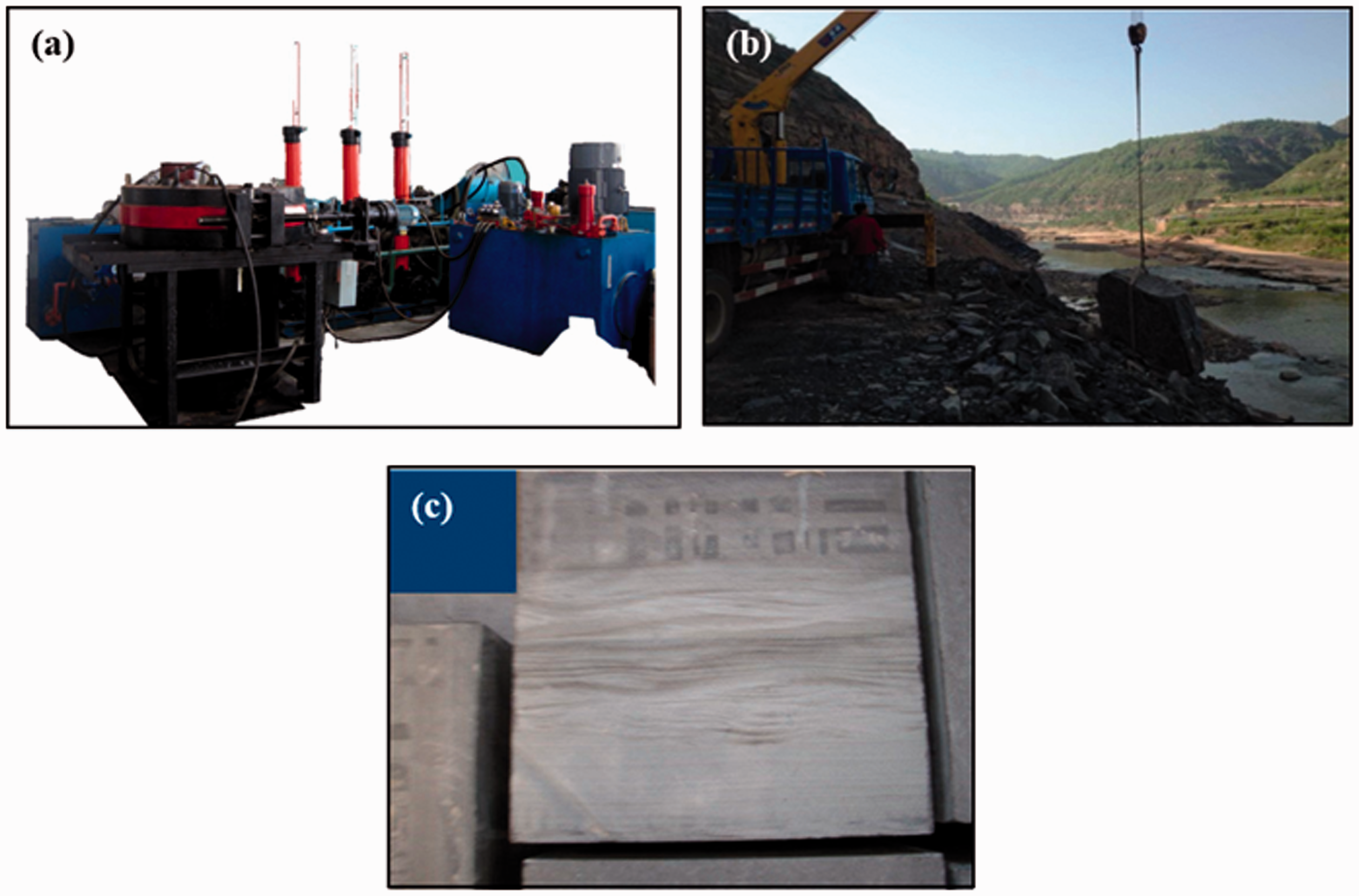
(a) Experimental apparatus (b) Outcrop collection and processing (c) Sample.
For the field outcrops of tight sandstone A without developed NFs and tight sandstone B with developed NFs, the weathered rock surface was cleaned, and the large scale outcrops were excavated (Figure 1(b)), and cut into the 300 mm × 300mm × 300mm samples (Figure 1(c)), including 7 sandstone A samples without developed NFs and 6 sandstone B samples with developed NFs. The 1.5 cm diameter bore hole was drilled in the center of the sample for placing the simulated wellbore, and the gap between the wellbore and the rock wall was bonded with the high-strength epoxy resin to prevent fluid leakage during fracturing. Figure 2(a) shows the perforated well bore and the single horizontal well bore. The perforated well bore simulates the three perforated holes. The single horizontal well bore is 12.5 cm long, and the 4 cm long open hole section is set below the wellbore. Figure 2(b) shows the dual-horizontal wellbores, which simulate the dual-horizontal wells simultaneous fracturing. The wellbore is 12.5 cm long, and the 4 cm long open hole section is set below the wellbore.
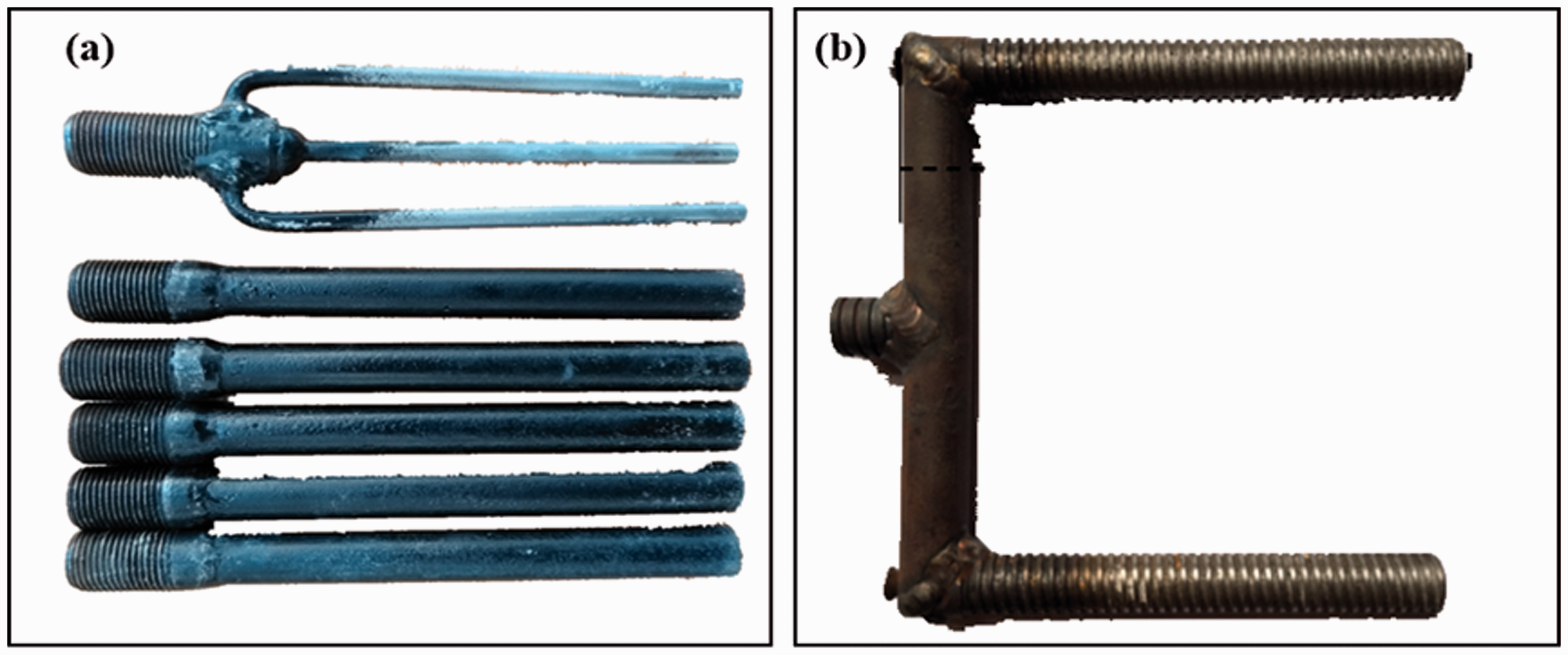
Simulated physical wellbore.
The tri-axial experiments were conducted in 13 standard samples of field outcrops. On average, the tight sandstone A samples have the tensile strength of 5.49 MPa, Young's modulus of 19.2 GPa and Poisson's ratio of 0.232, and are classified as the brittle rock with the brittleness index of 40.1, and the tight sandstone B samples have the tensile strength of 5.1 MPa, Young's modulus of 23.4 GPa and Poisson's ratio of 0.235, and are classified as the brittle rock with the brittleness index of 42.6.
Experimental scheme
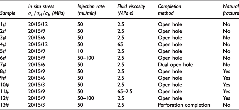
The HF propagation morphology in the tight sandstone was studied in terms of the NF development (with or without NFs), in-situ stress condition (different horizontal differential stress), treatment parameters (injection rate, fluid viscosity), multi-well simultaneous fracturing, and well completion methods. Thirteen sets of fracturing experiments were conducted, as listed in Table 1.
Physical simulation scheme for hydraulic fracturing of outcrop samples.
To simulate the horizontal well fracturing, the wellbores are placed along the direction of the horizontal minimum principal stress (
Experimental procedure
The sample is selected and put in the tri-axial high-pressure cylinder. The tri-axial stress is gradually loaded in the sample to the pre-defined value, and the stress is loaded simultaneously to ensure that the sample is uniformly stressed. When the confining pressure reaches the set value, the stress state is maintained. To observe the fractures, the blue or red ink is added to the fluid as a tracer, and the curve of pressure vs time is recorded. During fracturing, the AEM system is turned on to acquire the data. After completing the experiment, the pressure should be a vent, and the confining pressure should be gradually reduced. Finally, the sample is taken out of the chamber, photographed, and the fracture opening is observed. The chamber is cleaned and the above steps are repeated in the next experiment. Moreover, to analyze the HF propagation mechanism in the tight sandstone, the results of tight reservoirs are compared with those of the Xu 5th Member shale outcrop samples in the Sichuan Basin.
Analysis of results
Effect of horizontal differential stress
Tight sandstone samples without NFs
The horizontal differential stress is among the primary factors that determine the HF propagation morphology in the tight sandstone. Samples 1#, 2# and 3# are the tight sandstone A without NFs. The horizontal differential stresses of 3 MPa, 6 MPa and 9 MPa were loaded respectively, and the samples were fractured at a rate of 50 mL/min to investigate the effect of the horizontal differential stress on the HF morphology, as illustrated in Figures 3 to 5.
Experiment results of Sample 1#.
Experiment results of Sample 2#.
Experiment results of Sample 3#.
Only one HF is generated in Sample 1# under the horizontal differential stress of 3 MPa. The HF penetrates through the sample, but the fracture is not perpendicular to the horizontal wellbore but propagates at a certain angle with the wellbore. One HF is also generated in Sample 2# under the horizontal differential stress of 6 MPa and penetrates through the sample. The HF in Sample 2# is basically perpendicular to the wellbore and deflects nearly at the boundary. When the horizontal differential stress increases to 9 MPa, there is still one HF generated in Sample 3#. The HF penetrates through the sample, and the fracture is almost perpendicular to the horizontal wellbore, i.e. the fracture propagates along the σH direction.
As the horizontal differential stress increases, the HF more perpendicular to the horizontal well bore deflects less during propagation. Moreover, in the tight sandstone without developed BPs or NFs, conventionally hydraulic fracturing causes few HFs with the simple morphology, and the complex fracture network is hardly formed.
Tight sandstone samples with NFs
Samples 8#, 9# and 10# are the tight sandstone B with NFs. The horizontal differential stresses of 6 MPa, 9 MPa and 12 MPa were loaded respectively, and the samples were fractured at a rate of 50 mL/min.
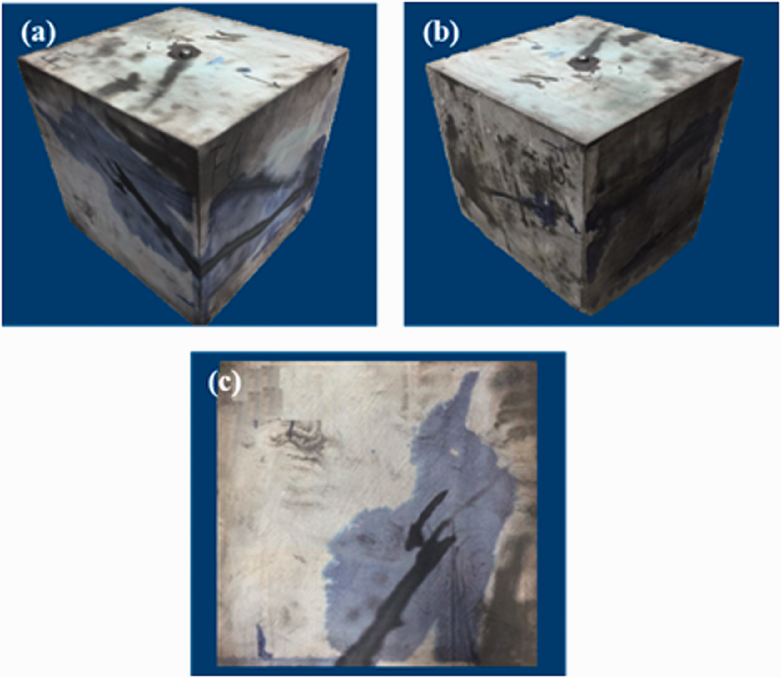
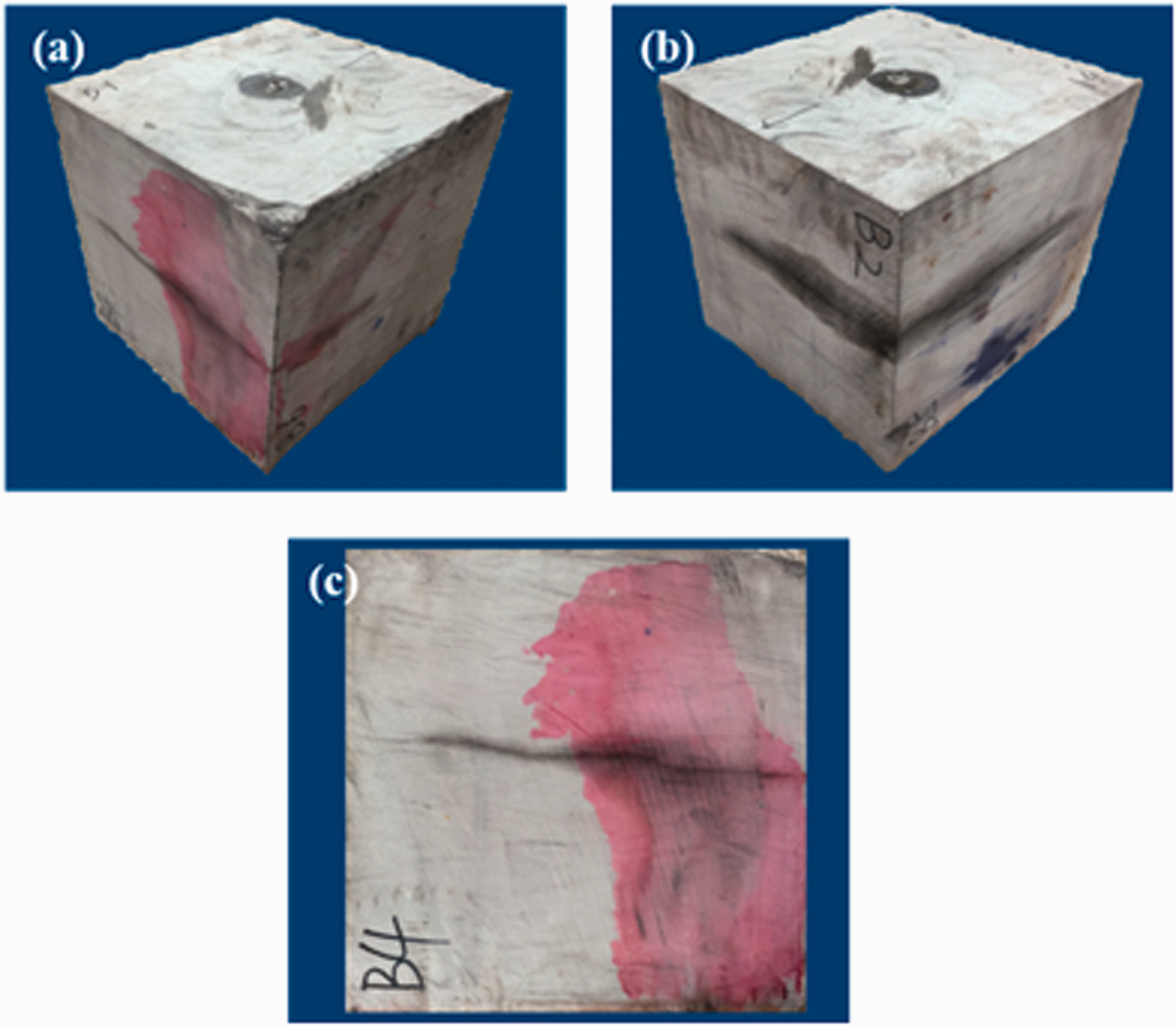
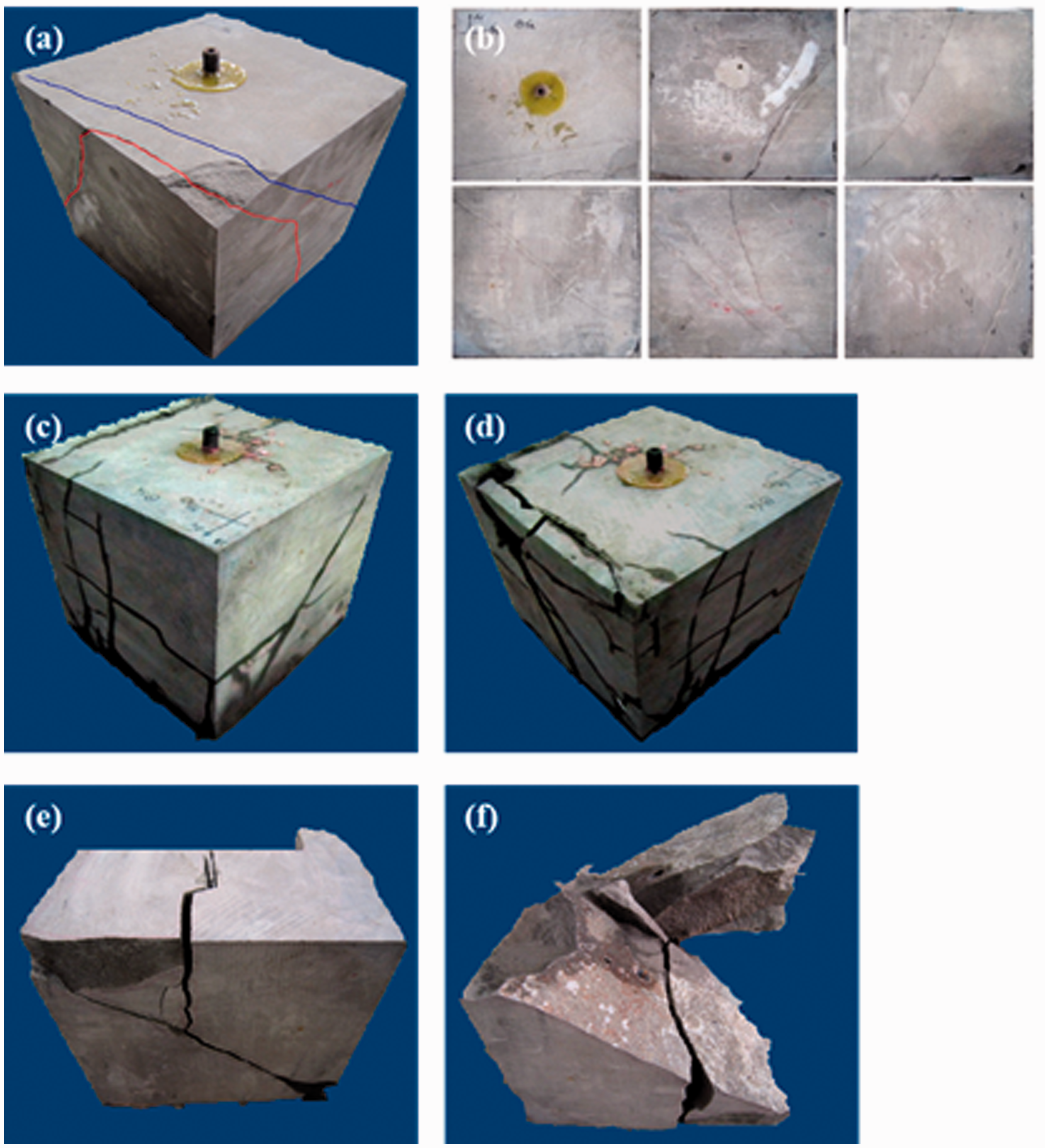
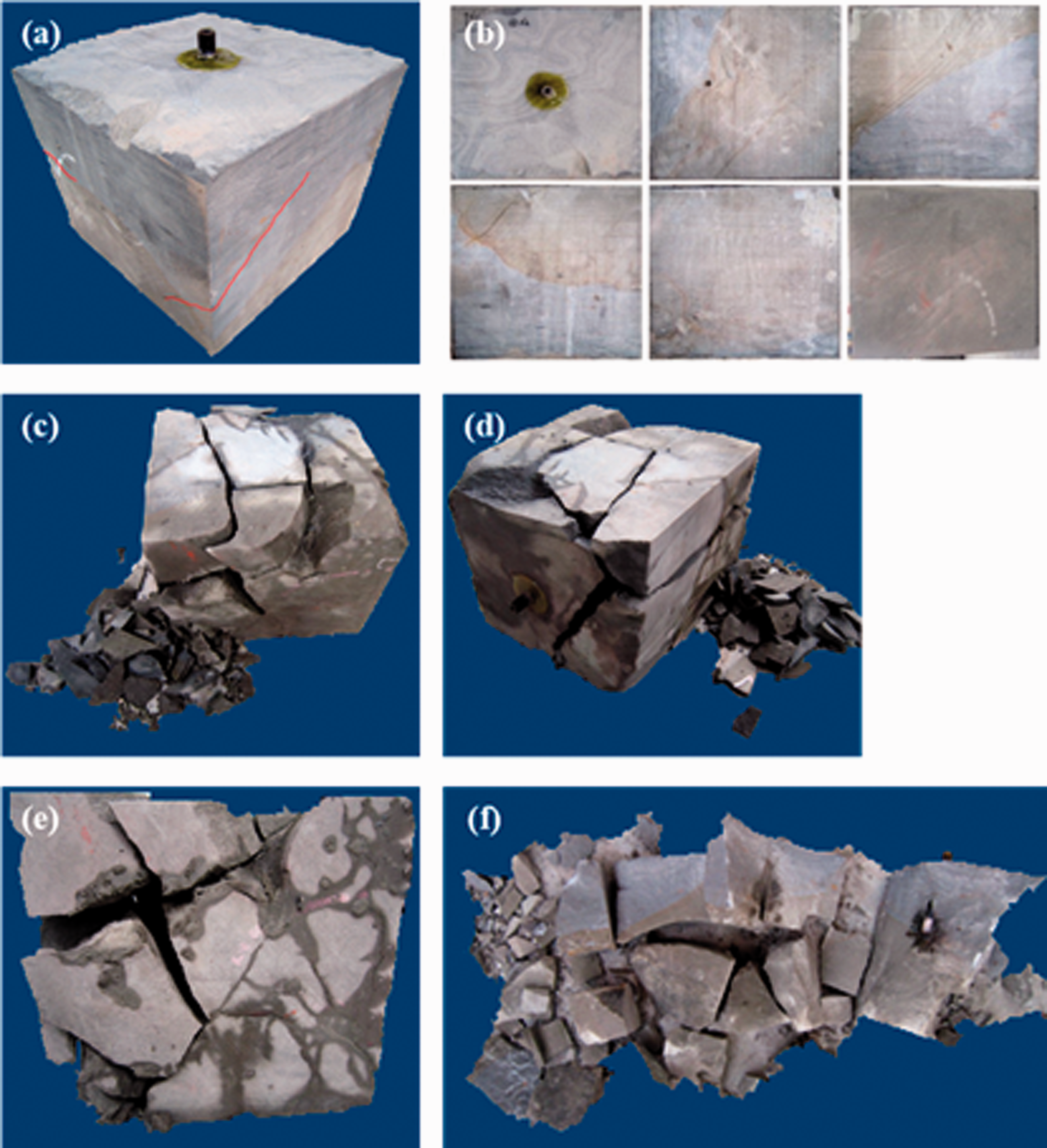
Sample 8# and its experiment results are illustrated in Figure 6. Sample 8# displays the developed NFs before fracturing, and NFs are observed on five faces. The NFs include the clay-filling, weakly cemented NFs with a certain opening, which are marked by the red line, and the siliceous-filling strongly cemented NFs, which are marked by the blue line (Figure 6(a)). After fracturing, several NFs are opened in Sample 8#, and the fracture network system is more complicated than that in the sandstone without NFs. After the fracturing fluid enters the open-hole section, the NFs marked by the red line are opened, and then, the HF propagates along the cemented plane, forming a primary fracture intersecting with the well bore at 45° in the upper part and at about 30° in the lower part (Figure 6(e)). Meanwhile, other NFs that intersect this HF at various angles are communicated with, forming the NF network with a certain complexity (Figure 6(d)). During fracturing, the NFs marked by the blue line are not communicated with, and no transverse HF is generated along the σH direction. The fracture pressure is close to the propagation pressure and is about 11–12 MPa.
Sample 8# and its experiment results.
Under the horizontal differential stress of 6 MPa, hydraulic fracturing leads to the fracture network with a certain complexity by communicating weakly cemented NFs in the sandstone with developed NFs, and the SRV is much larger than that in the sandstone without developed NFs, but it is difficult to form the deeply penetrating transverse primary fracture.
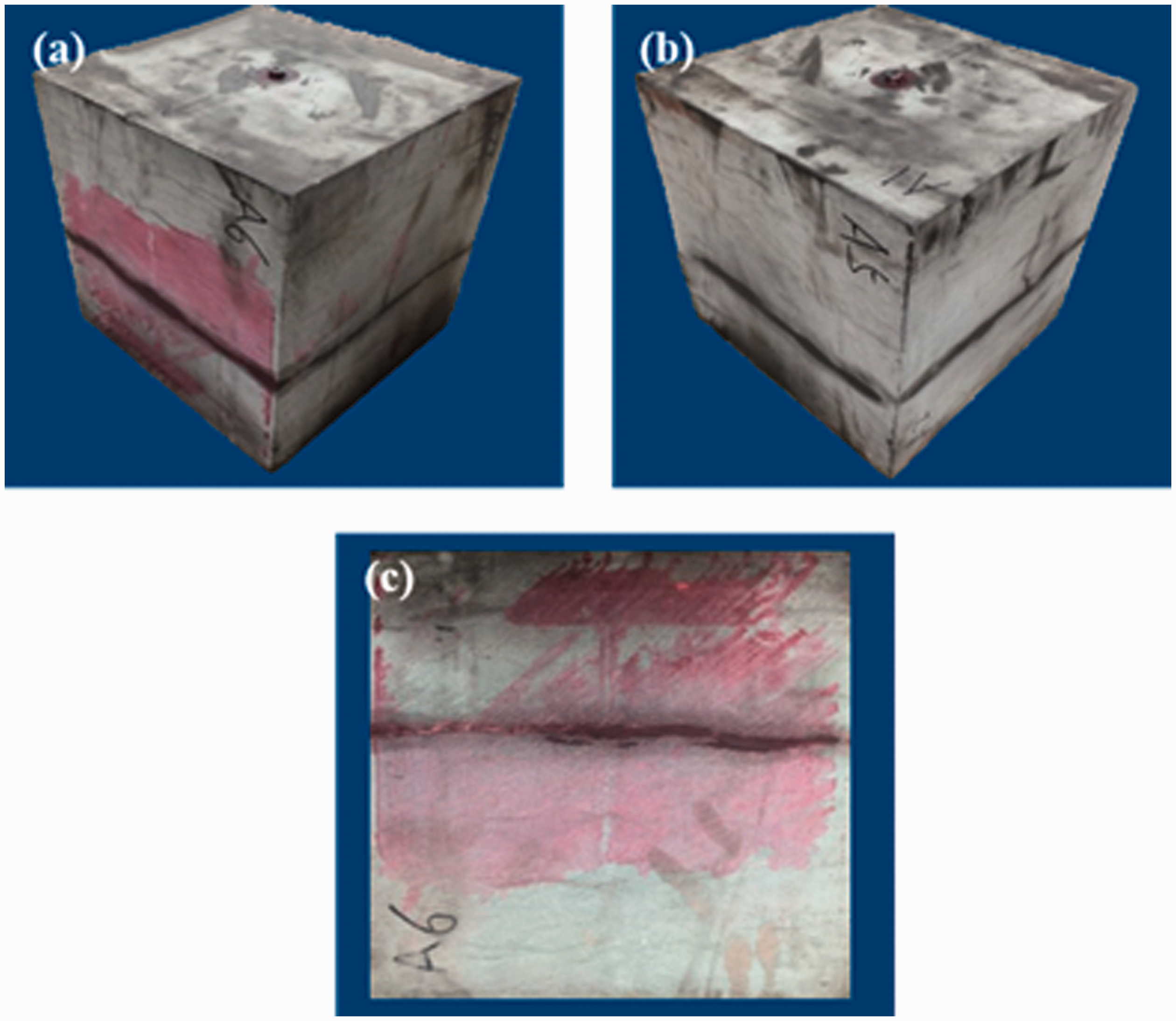
Sample 9# and its experiment results are illustrated in Figure 7. Sample 8# displays the developed NFs on 4 faces before fracturing, and they are dominated by the strongly cemented NFs without opening (Figure 7(a) and (b)).
Sample 9# and its experiment results.
The relatively complicated HF network is also formed in Sample 9#. The fracture is initiated from and propagates along a 30° dip weak plane that intersects the open hole. The lower part of the fracture reaches the sample boundary, and the upper part communicates with other NFs, forming the fracture network with a certain complexity (Figure 7(e) and (f)). During fracturing, no HFs across the wellbore are generated. The fracture pressure is about 10 MPa, and the propagation pressure is 8-10MPa.
Under the horizontal differential stress of 9 MPa, the HF still propagates primarily along the NFs and communicates with the weakly cemented BPs and some strongly cemented NFs in Sample 9#.
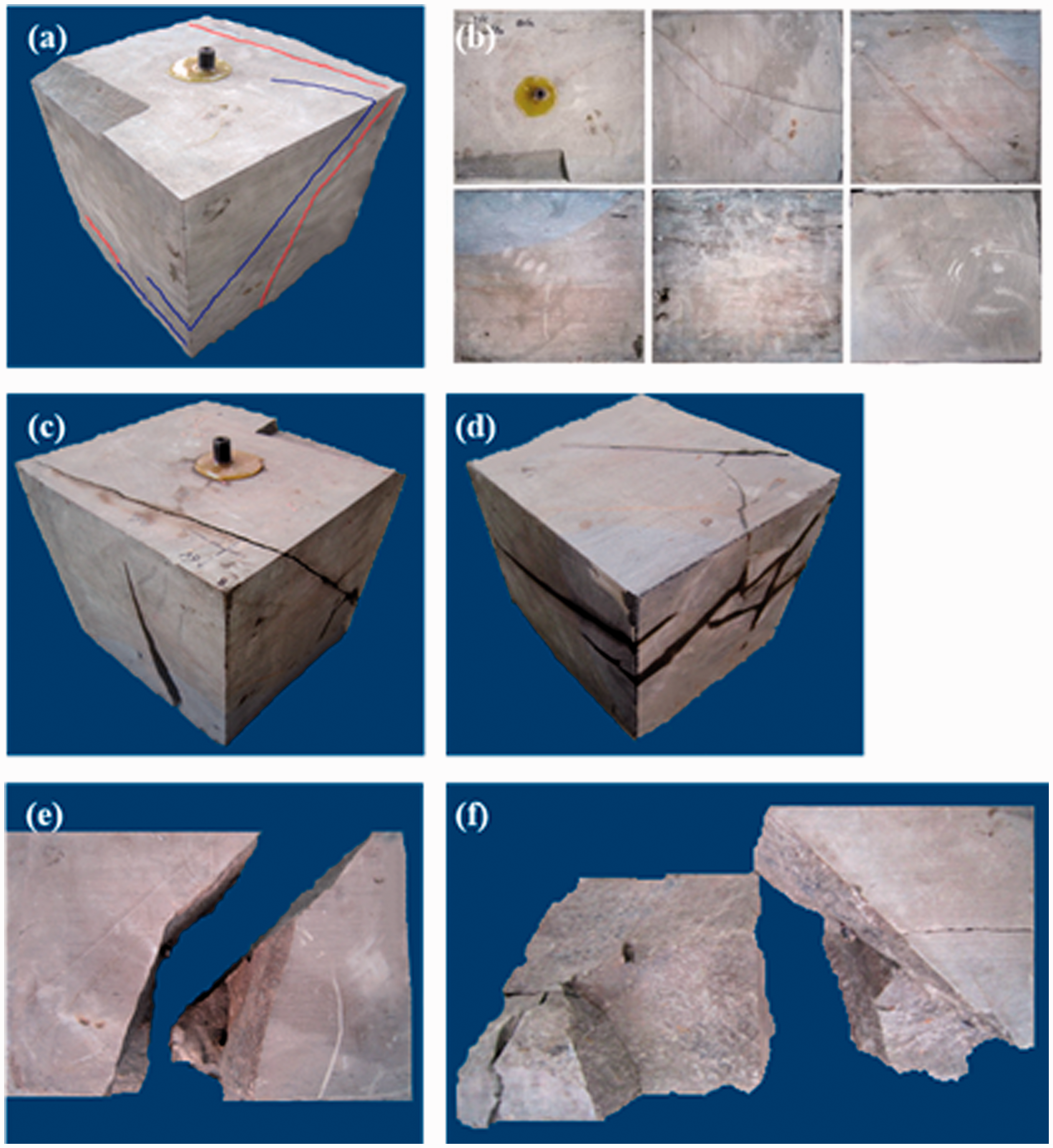
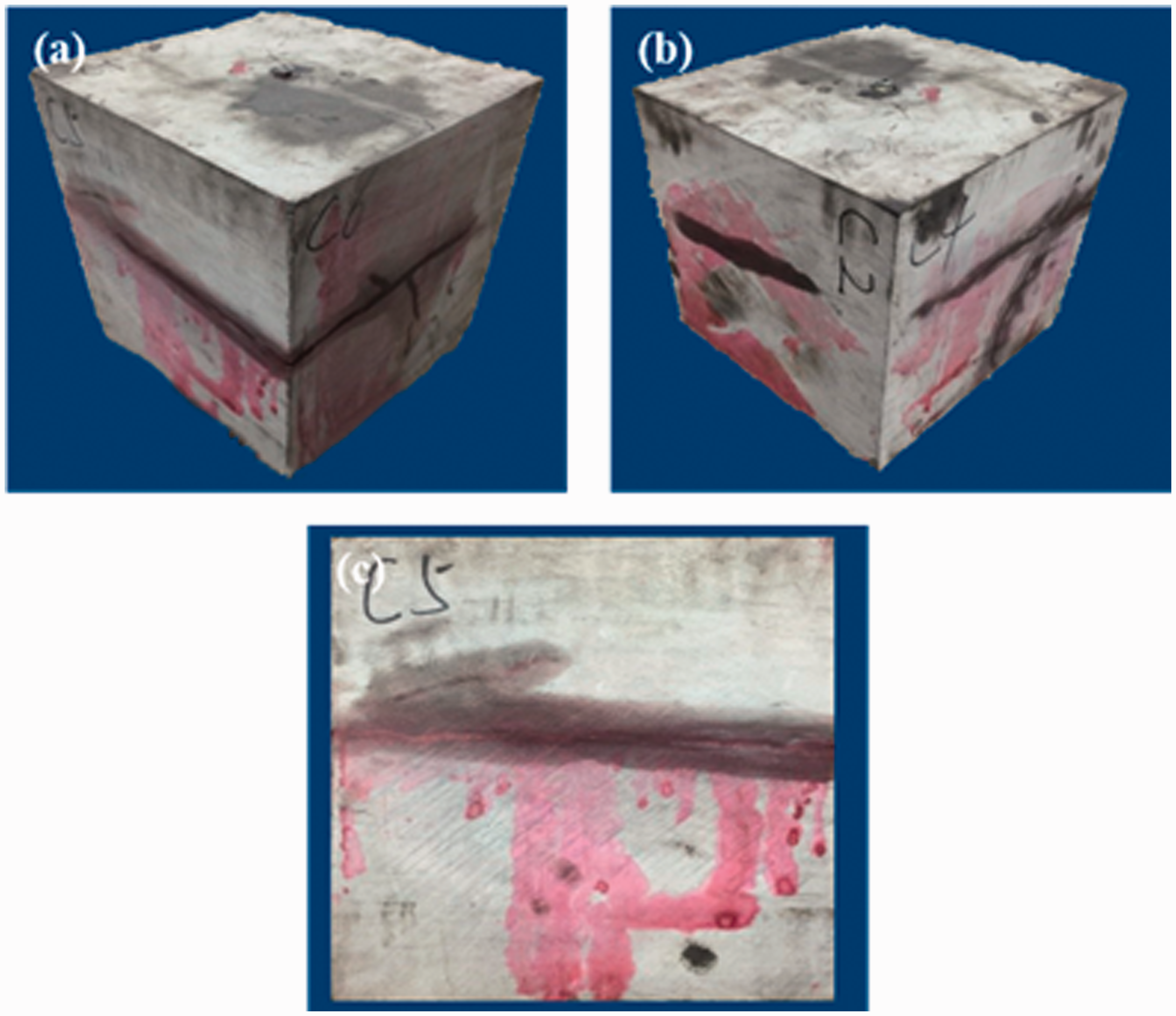
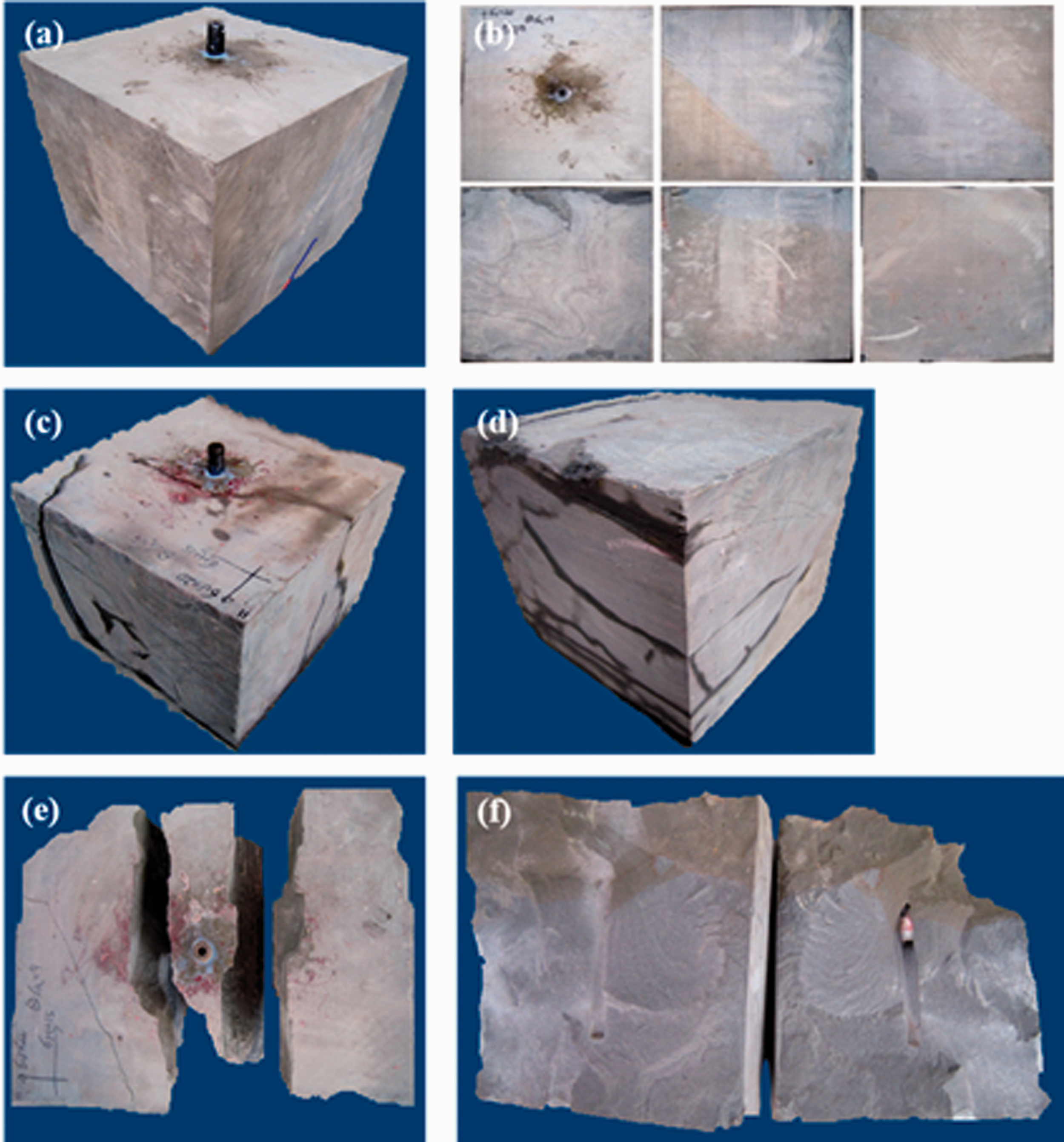
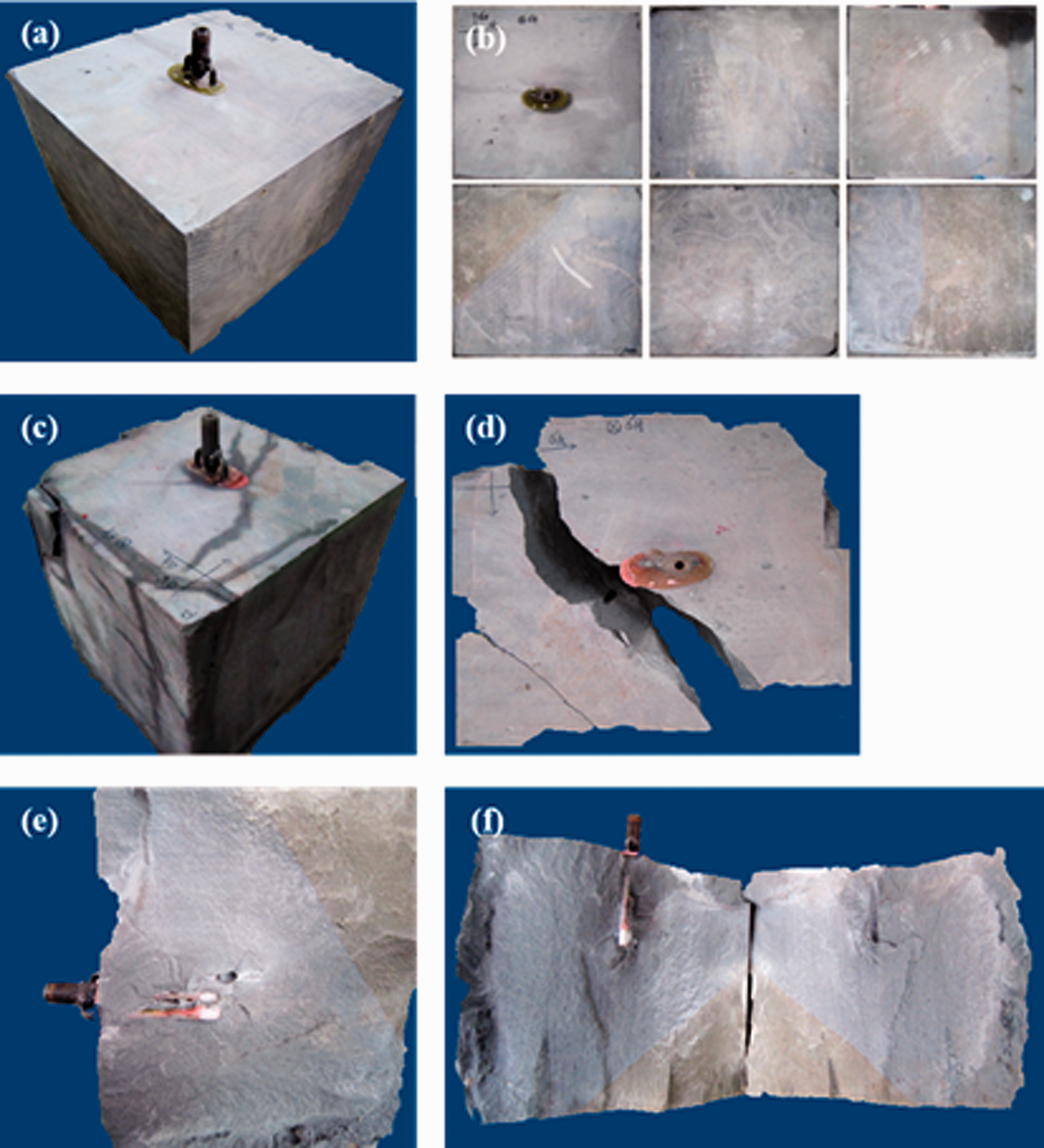
Sample 10# and its experiment results are illustrated in Figure 8. Sample 10# displays both weakly and strongly cemented NFs on 6 faces before fracturing (Figure 8(a) and (b)).
Affected by the high horizontal differential stress of 12 MPa and the highly developed NFs, the HF is generated across the wellbore (Figure 8(e) and (f)), opens the NF intersecting with the wellbore with an angle of 45° during propagation, and communicates with other NFs that intersect with this NF, forming the complex fracture network. Moreover, the transverse HF does not pass through the NF but is diverted at both fracture ends when propagating to the strongly cemented NFs at an intersection angle of 45°. The fracturing pressure curve shows peaks at 5 MPa, 12 MPa and 17 MPa, indicating the massive fracturing within the sample.
Sample 10# and its experiment results.
To sum up, in the tight sandstone with the developed NFs, more strongly cemented NFs are communicated with the HF in the horizontal well fracturing as the horizontal differential stress of the reservoir increases, and the HF is generated across the well bore, forming the more complicated fracture network.
Shale samples
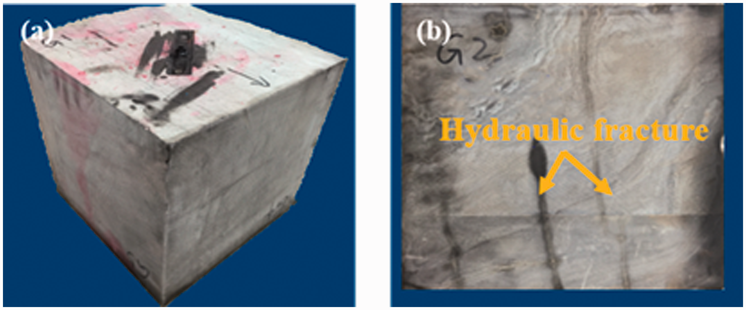
Two shale outcrop samples from the Xu 5th Member in the Sichuan Basin were cut to carry out the experiment for comparison with the above results. The results of shale fracturing under the horizontal differential stress of 3 MPa and 6 MPa and the CT scan results are illustrated in Figures 9 and 10 respectively.
Fracture morphology and CT scan result of the shale fractured under the horizontal differential stress of 3 MPa.
Fracture morphology and CT scan result of the shale fractured under the horizontal differential stress of 6 MPa.
Under the horizontal differential stress of 3 MPa, no obvious transverse fractures are generated in the shale sample. Under the low horizontal differential stress, the HF is difficult to penetrate the NFs around the well bore. During fracturing, the fluid preferentially flows or leaks off along the opened NFs or BPs. When the propagation is stopped, the pressure will rise, and more weakly cemented NFs are opened, forming a narrow stimulation belt consisting of single direction NFs. Under the horizontal differential stress of 6 MPa, the HF opens and communicates with the BPs or NFs through propagation and penetration, finally forming a complex fracture network.
Thus, hydraulic fracturing of the tight sandstone without developed NFs only leads to a single symmetrical double-wing primary fracture, and the horizontal differential stress mainly controls the fracture initiation and propagation direction. For the shale or the tight sandstone with developed NFs, the fracture propagation path is primarily controlled by the high stress difference. Under the higher stress difference, the BPs or NFs systems are opened by or communicated with the HF, forming the complex fracture network and increasing the SVR.
Effect of fracturing fluid viscosity
In shale fracturing, the fracturing fluid viscosity is a primary engineering factor that controls the HF morphology. Sample 4# (without developed NFs) was fractured with the high-viscosity guar gum, and Sample 11# (with developed NFs) was fractured with the variable-viscosity fluid (65–2.5 mPa) to explore the effect of fracturing fluid viscosity on the fracture morphology. Based on the experimental conditions of each specimen, the results of Sample 4# and Sample 1# were compared to analyze the fracturing effect of high or low viscosity fluid. At the same time, the results of Sample 11# and Sample 8# were compared to explore the influence of variable-viscosity fluid on fracture morphology.
According to the results of Sample 4# in Figure 11, fracturing the tight sandstone without NFs and BPs with the high-viscosity fluid also leads to a simple symmetrical double-wing HF, which is similar to those fractures generated with the low-viscosity fluid (Sample 1#). The experimental results show that only using low or high viscosity fracturing fluid has little effect on the fracture morphology formed by fracturing in the tight sandstone.
Rock sample 4# and its experiment results.
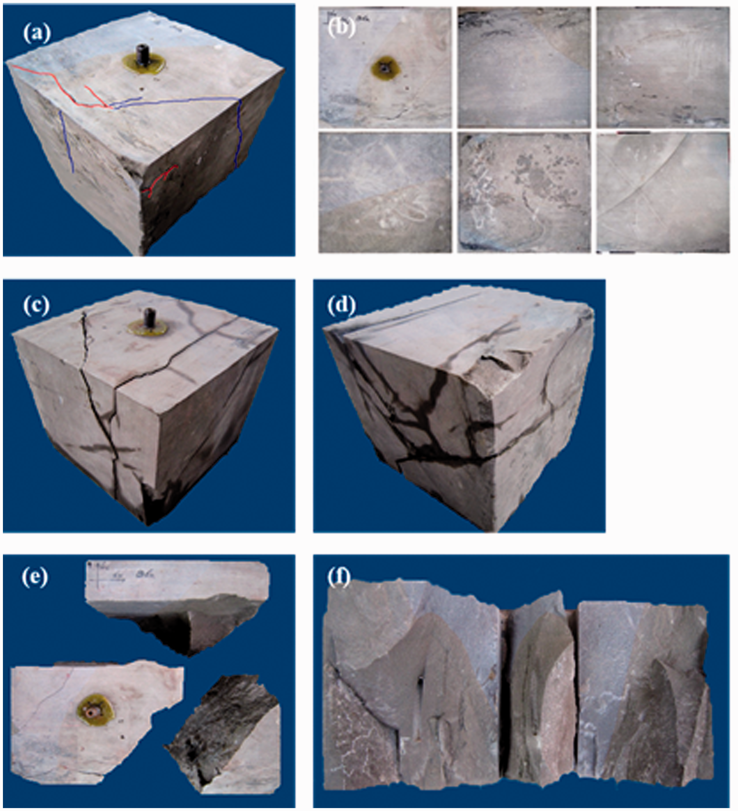
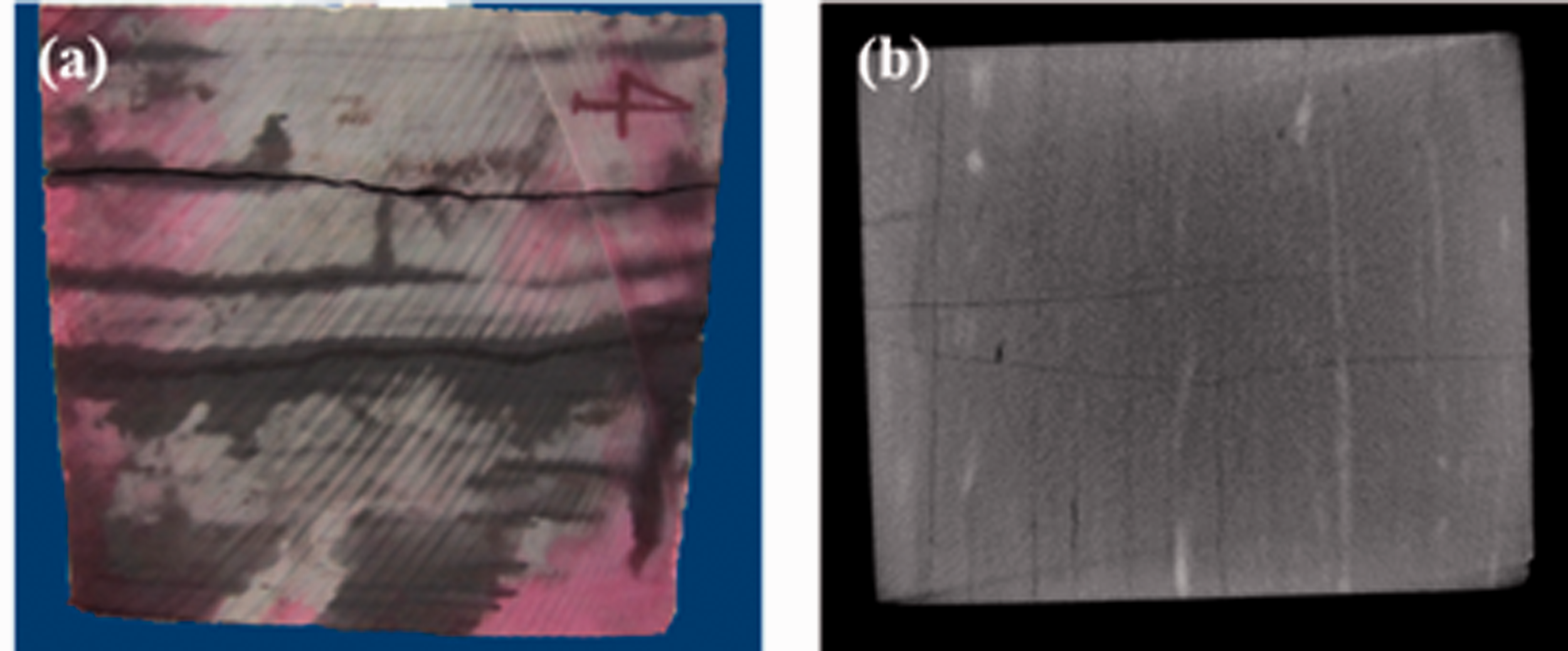
The results of Sample 11# are illustrated in Figure 12. Before fracturing, Sample 11# displays the weakly cemented NFs with a certain opening (Figure 12(a) and (b)). The sample was fractured with 13 ml of 65 mPa·s guar gum (prevent the HF propagation to the boundary and the influence on the slick water injection with less fluids) in the early stage and the 2.5 mPa·s slick water slug in the late stage. After fracturing, the extremely complex fracture network was formed, and a large number of fragments were collapsed. It is difficult to hold the entire sample. CT scan of the fractured sample shows a HF transverse to the horizontal wellbore, and the HF communicates with the weakly cemented NFs oblique to the wellbore. It is estimated that the high-viscosity guar gum produces a higher net pressure and a lower fluid loss, resulting in a transverse primary fracture in the open hole and opening the weakly cemented BPs around the well bore. Later, the low-viscosity slick water penetrates into the pores and micro-cracks and communicates with several NFs intersecting them, forming a complex fracture network (Figure 12(c) and (d)). Overall, the HFs have the various angles, and some are perpendicular to the
Sample 11# and its experiment results.
It can be seen that compared with the Sample 8# only using low viscosity fracturing fluid (other conditions are consistent with Sample 11#), the number of fractures and the complexity of fracture network of Sample 11# with variable-viscosity fluid increased significantly. The results show that the fracturing with variable-viscosity fluid can greatly increase the number of fractures and the complexity of fracture network, and effectively improve the volume of reservoir reconstruction.
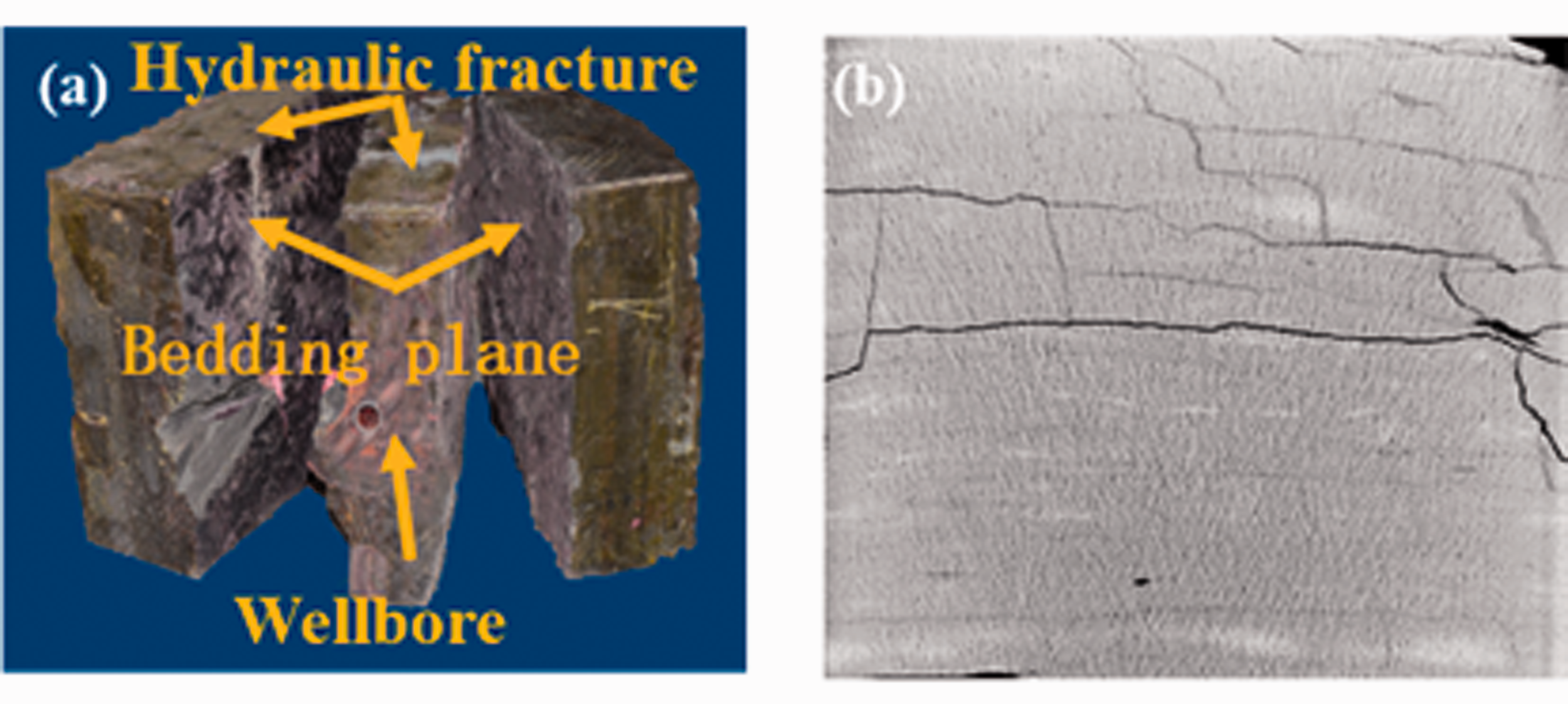
The shale outcrop samples of the Xu 5th Member were cut to carry out the experiment for comparison with the above results. The results of shale fracturing under the horizontal differential stress of 3 MPa and the CT scan results are illustrated in Figure 13. When the shale with developed NFs and BPs is fractured with the high-viscosity guar gum, the fracturing fluid is difficult to filter into the weakly cemented NFs and BPs but directly penetrates them, forming a single HF, which has much less complexity compared with the HF generated with the low-viscosity slick water (Figure 9).

Fracture morphology and CT scan result of the shale fractured with the high-viscosity fracturing fluid.
The fracturing fluid viscosity has a significant effect on fracture propagation. The high-viscosity fracturing fluid leads to the high net pressure and the low fluid leak-off within the fracture, and is not easy to filter into and open the micro-cracks. The simple transverse fracture is always generated, and it is difficult to form a fracture network. The invasive wettability of the low-viscosity fracturing fluid facilitates reducing the friction coefficient of the NF wall, promoting the NF shear slip, opening the NFs and enhancing the fracture complexity. In fracturing with the combined high and low-viscosity fluid slugs, the low-viscosity slick water injected later facilitates forming the complex fracture network with its invasive wettability. It is recommended to fracture the tight sandstone with the developed NFs by injecting the high-viscosity guar gum firstly and pumping the low-viscosity slick water then, and both the deeply penetrating transverse fractures and the complex branched fractures are generated, increasing the SRV.
Effect of injection rate
The injection rate is also a primary engineering factor that controls the HF morphology. The low-rate fracturing facilitates opening of NFs, and the high-rate fracturing facilitates generation of the HF. Sample 5# was fractured at a low rate of 10 mL/min, and Samples 6# and 12# were fractured at a high rate of 50–100mL/min. Based on the experimental conditions of each specimen, the results of Sample 5# (low constant injection rate), Sample 6# (variable injection rate) and Sample 2# (high constant injection rate) were compared to analyze the fracture morphology difference in the reservoir without NFs. At the same time, the results of Sample 12# and Sample 8# were compared to explore the fracture propagation law of constant injection rate and variable injection rate fracturing in the reservoir with NFs.
The results of Sample 5# are illustrated in Figure 14. Only one transverse HF is generated due to lack of NFs and BPs in the sample. The fracture number and morphology in Sample 5# are not much different with those in Sample 2# (other conditions are consistent with Sample 5#) fractured at a rate of 50 mL/min. The low and high injection rate have little effect on HF propagation in the reservoir without developed NFs and BPs. Nevertheless, considering the characteristics of fracturing with high and low injection rates, a variable-rate fracturing method was applied to try to generate the complex fracture system in the tight sandstone without developed NFs.
Experiment results of Sample 5#.
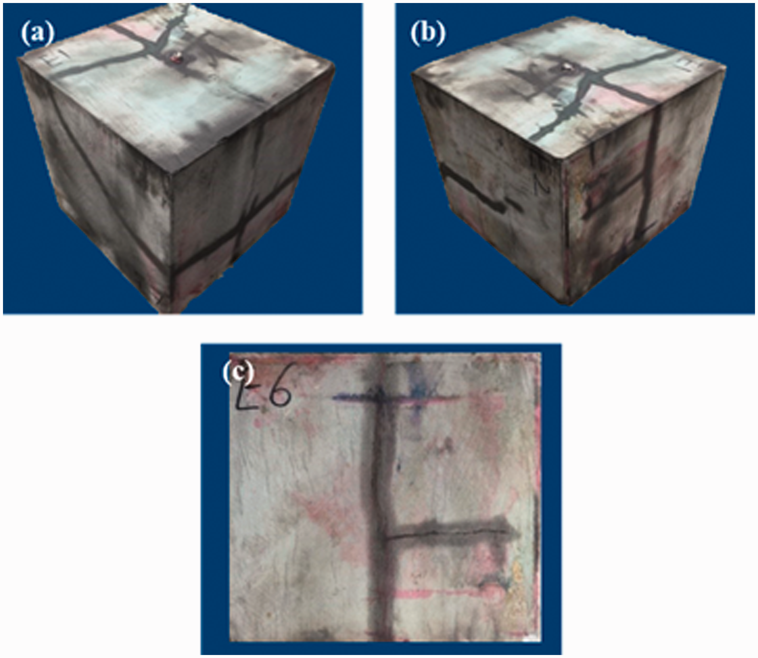
Sample 6# and its experiment results are illustrated in Figure 15. Sample 6# only has one strongly cemented NF on a face before fracturing and was fractured at the variable rate. The rate was set at 50 mL/min initially and increased to 100 mL/min rapidly after fracture initiation. Sample 6# has the fracture with a higher complexity compared with Sample 2# and Sample 5# with only one transverse fracture, and two primary fractures (Figure 15(e) and (f)) parallel to the wellbore and perpendicular to the overlying stress are generated in Sample 6#. The measured fracture pressure is close to 23 MPa, which is due to the high integrity in the open hole not cemented with the resin glue. The slick water is difficult to filter into the low-permeability pores in the open hole, but the fluids at the low injection rate easily penetrate into the weakly cemented NFs oblique to the wellbore. In the later stage of the experiment, the rate was increased to 100 mL/min, and the pressure build up velocity within the wellbore was much higher than the fluid diffusion velocity of the fracturing fluid within the fracture. The pressure builds up instantaneously in the open hole and overcomes the
Experiment results of Sample 6#.
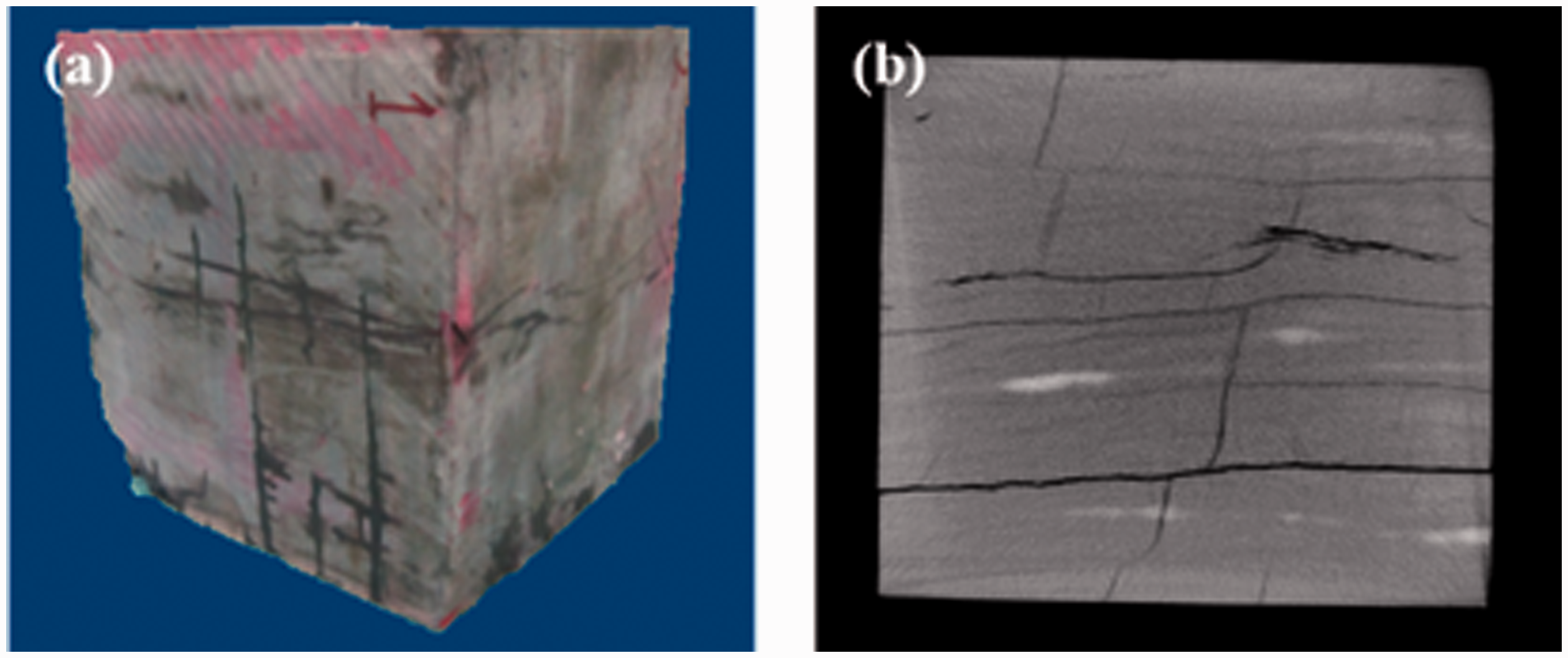
Sample 12#, which is the sandstone with developed NFs, is fractured at a variable rate, and its fracturing results are illustrated in Figure 16. Multiple HFs are generated in the sample and communicate with multiple BPs and BPs, forming the fracture network system. The reason is that the initial low injection rate leads to a slower pressure build up velocity, and the fracturing fluid easily penetrates into NFs. Then, at a high injection rate, the pressure continues to increase, and a transverse primary fracture and some NFs are opened, forming a more complex fracture network. Compared with the Sample 8# with constant injection rate, the number of fractures and the complexity of fracture network in Simple 12# are significantly higher than that of Sample 8#, which indicates that the fracturing with variable injection rate is obviously beneficial to increase reservoir reconstruction volume.
In summary, the variable rate fracturing method can enhance the HF complexity. It is recommended to apply the fracturing with alternated high and low injection rates to generate a large scale fracture network system.
Experiment results of Sample 12#.
Effect of dual-horizontal wells simultaneous fracturing
The dual-horizontal wells simultaneous fracturing, a method to increase the HF number and enhance the HF complexity, was simulated by placing two connected horizontal wellbores in different layers of the tight sandstone sample without developed NFs under the high horizontal stress difference. The results of Sample 7# are illustrated in Figure 17. Two approximately parallel HFs are generated, and they are initiated from the wellbores and propagate along the
Experiment results of Sample 7#.
The results of the dual-horizontal wells simultaneous fracturing in the shale, as shown in Figure 18, show that the HFs are difficult to be initiated simultaneously from the two wellbores, which is primary due to the strong heterogeneity of the shale. However, when the transverse fractures are generated simultaneously in the two wellbore, a large-scale complex fracture network is formed possibly due to the existence of NFs.
Fracture morphology and CT scan result of the dual-horizontal wells simultaneous fracturing in the shale.
Effect of the completion methods
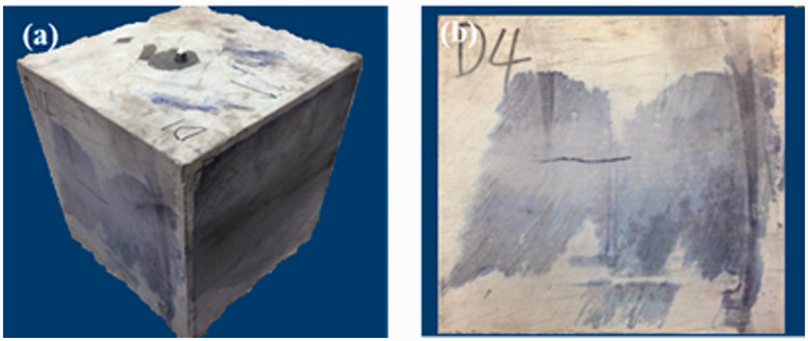
A wellbore with three holes with the azimuth of 0° was placed in Sample 13# to investigate the effect of the completion methods on the HF morphology in the tight sandstone. Sample 13# and its experiment results are illustrated in Figure 19. The sample displays no NFs before fracturing (Figure 15(a) and (b)). After fracturing, a HF is generated along the
Sample 13# and its experiment results.
Relationship between the treatment pressure and the HF morphology
Statistics of the fracturing curves of 13 tight sandstone samples and 5 shale samples was performed (Figure 20) to obtain the relationship between the treatment pressure and the fracture morphology. In general, there are four types of fracturing curves: (a) the non-obvious fracture pressure and stable propagation pressure; (b) the obvious fracture pressure and rapidly declining pressure when the fracture pressure is reached and the HF is opened; (c) the injection pressure varied with the rate in the variable rate farcturing; (d) the obvious fracture pressure and extremely fluctuated propagation pressure. The relationship between the fracture curve and fracture morphology is as follows.
Injection pressure curve of samples. First: the fracture pressure is not obvious, and the propagation pressure is close to the fracture pressure, and extremely stable during fluid injection (Figure 20(a)). This is common in the fracturing simulation of the shale and the tight sandstone with NFs. No obvious HFs are observed in the rock samples, and only multiple BPs are opened (Figures 9, 10 and 13). Second: the fracture pressure is obvious. When the injection pressure reaches the fracture pressure, the HF is opened and the pressure declines rapidly (Figure 20(b)). This is common in fracturing simulation of the tight sandstone sample without developed NFs, and only one HF is generated. (Figures 3 and 4). Third: the injection pressure starts to decrease when reaching the fracture pressure, and the injection pressure continues to rise when increasing the injection rate and drops rapidly after reaching the another fracture pressure (Figure 20(c)). This is common in the fracturing simulation of the tight sandstone at a variable rate. When the fracture pressure is reached for the first time, the HF is initiated and propagates. When increasing the injection rate, the pressure continues to rise, forming a new HF (Figures 15 and 16). Fourth: the injection pressure decreases when reaching the fracture pressure, and then the propagation pressure increases rapidly and decreases then. The injection pressure fluctuates very frequently (Figure 20(d)). This is common in the fracturing simulation of the tight sandstone with developed NFs. The HF is generated when the injection pressure reaches the fracture pressure, and the HFs are communicated with multiple NFs when the propagation pressure fluctuates abnormally. The HF is communicated with multiple NFs during its propagation (Figure 12).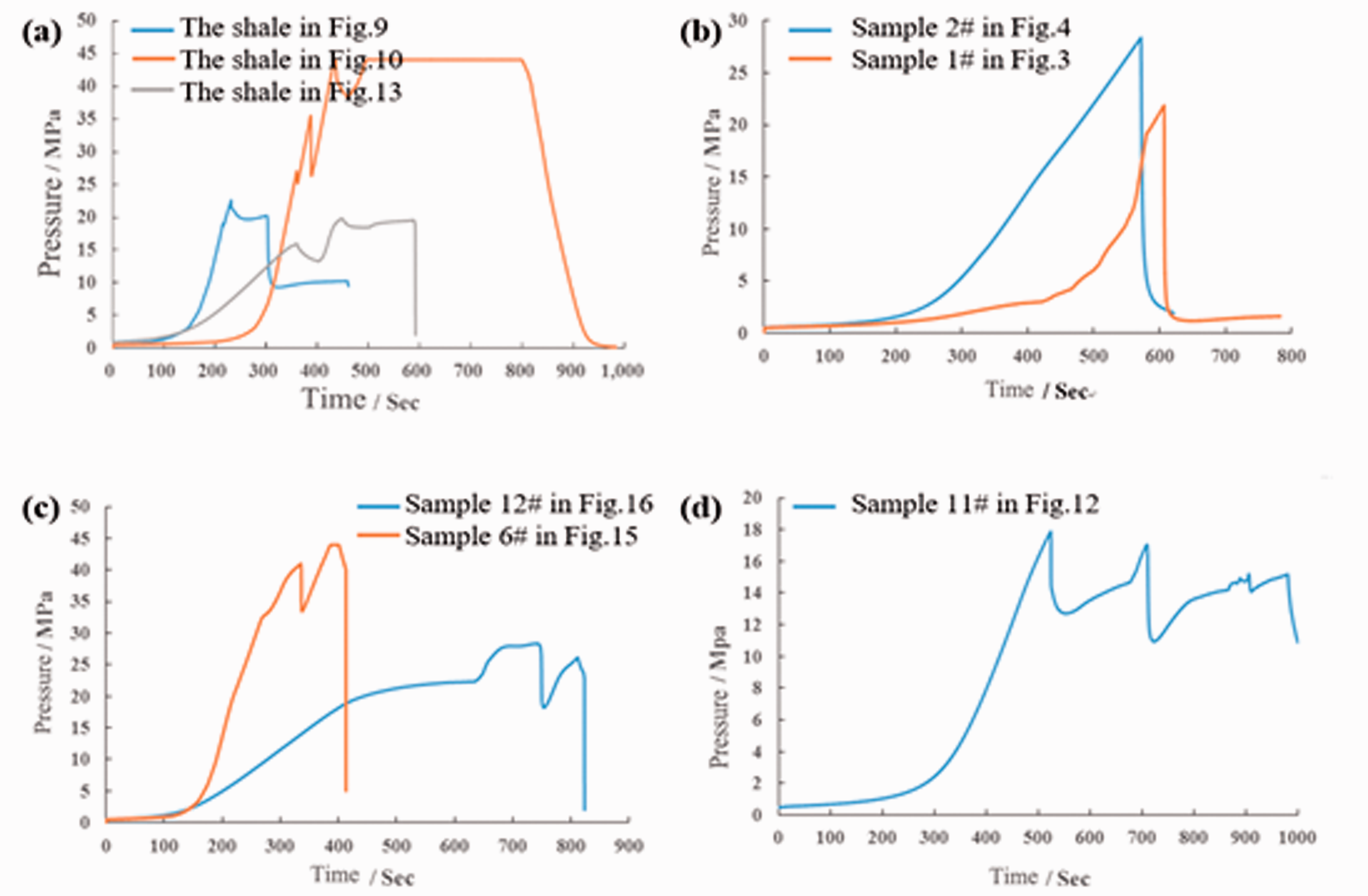
Conclusions
The true tri-axial fracturing simulations were carried out in two types of tight sandstone outcrop samples, and the effects of the NF development, in-situ stress conditions, treatment parameters, fracturing methods, etc. on the HF propagation morphology in the tight sandstone were studied. The results were compared with the fracturing simulation of shale outcrop samples. The conclusions are as follows.
Conventional fracturing of the tight sandstone without NFs only produces a single double-wing primary fracture. The fracture propagation path in the shale or the tight sandstone with developed NFs is controlled by the high horizontal differential stress. Under the higher stress difference, the BPs or NFs systems are opened by or communicated with the HF, forming the complex fracture network. The high-viscosity fracturing fluid leads to the high net pressure and the low fluid leak-off within the fracture, and is not easy to filter into and open the micro-cracks. The simple transverse fracture is always generated, and it is difficult to form a fracture network. The low-viscosity fracturing fluid injected later facilitates generating the complex fracture by interacting with the NFs. It is recommended to fracture the tight sandstone reservoir with the developed NFs by injecting the high-viscosity guar gum firstly and pumping the low-viscosity slick water then. The low injection rate facilitates the fracturing fluid filtration into the NF system, and the high injection rate increases the net pressure within the fracture, overcomes the high stress difference to open NFs at any angle, and produces the transverse primary fracture. Fracturing at a low-high variable rate can overcome the vertical stress difference of nearly 11MPa and open the weakly cemented NFs, increasing the SRV. It is recommended to fracture the tight sandstone reservoir with variable injection rate. The dual-horizontal wells simultaneous fracturing increases the HF density and enhances the HF complexity in the tight sandstone reservoirs, significantly increasing the possibility of forming the large-scale complex fracture network. In the perforation completion, the perforated section has the small size and is less likely communicated with NFs, and thus, the fracture tends to be initiated from the perforation hole, resulting a higher fracture pressure. In the sample without developed NFs, the HF propagates by overcoming the horizontal principal minimum stress, forming a single primary fracture. The fracturing curve reflects the HF propagation state and is mainly divided into the types corresponding to opening of multiple BPs in the shale, generation of a single fracture in the tight sandstone, initiation and propagation of multiple fractures at a variable rate and forming the fracture network by communicating the HF with the NFs. In the field construction, the fracture morphology formed in the downhole can be roughly distinguished by hydrofracture construction curve according to the corresponding relation.
Footnotes
Declaration of conflicting interests
The author(s) declared no potential conflicts of interest with respect to the research, authorship, and/or publication of this article.
Funding
The author(s) disclosed receipt of the following financial support for the research, authorship, and/or publication of this article: The authors would like to acknowledge the financial support of the National Natural Science Foundation of China (Grant No.51874338), and express their gratitude to the project ZR2019QEE005 supported by the Shandong Provincial Natural Science Foundation.