
Abstract
The distribution of remaining oil is affected by a number of geological and engineering factors. However, previous studies have mainly focused on the effect of a certain factor or some factors on the distribution of remaining oil. Therefore, this research considers subaqueous distributary channels of Fuyu oil layer in the Fuyu oilfield as a case with following investigations: analysis of the controlling effects of micro-structure, sedimentary micro-facies, single sand body stacking, architecture elements, flow units, well patterns and injection–production relationships on the distribution of remaining oil. Using the coupled effects of multi-factors method, five models of the remaining oil distribution are established as follows: model one includes micro-structure, sedimentary micro-facies, and injection–production relationship; model two includes micro-structure, sedimentary micro-facies, single sand body stacking; model three includes the secondary micro-facies, flow units, and well pattern; model four includes sedimentary micro-facies, single sand body, and injection–production relationship; and model five includes sedimentary micro-facies, architecture elements, flow units, and injection–production relationship. These five models are effective in the study of remaining oil in Fuyu oilfield and can also have a certain example for the other maturing oilfield.
Introduction
The term ‘remaining oil’ refers to the oil trapped in an oil reservoir after exploitation for a period of time or of a certain amount (Li, 2003; Liu and Xu, 2003). In its existing form, remaining oil can be divided into residual oil and movable oil. There are many factors that control the distribution of remaining oil, including geological and engineered factors. In previous studies, researchers have extensively investigated to find that sand body size less than the distance between water well and oil well (Du et al., 2004; Yu, 2008), seepage discrepancy of different layers (Shi et al., 2005), thick positive rhythm sand bodies (Wang et al., 2006), lateral interlayers in thick sand bodies (Han, 2007; Liu et al., 2006) are one of the main factors for accumulating remaining oil. Sand bodies that are quite thick and appearing at the fork of subaqueous distributary channels are advantageous for the accumulation of remaining oil (Lin et al., 2011). Based on the physical simulations using sand boxes, some scholars have noted that remaining oil accumulates near interlayers and that the horizontal extent of interlayers affects the distribution of the remaining oil (Yue et al., 2012). However, previous studies have mainly focused on the effect of a certain factor or some factors on the distribution of remaining oil (Yue et al., 2007), and studies on the coupled effects of multiple factors are less. Therefore, the authors of this study consider Fuyu oil layer (the fourth member of Quantou Formation, Fuyu oilfield) as an example, analyzed the influence of micro-structure, sedimentary micro-facies, single sand body, architecture elements, flow units, well patterns, and relationships between injection and production on the distribution of the remaining oil. The key controlling factors were identified and used to establish a model for the remaining oil distribution based on the coupled effects of multiple factors (Aggoun et al., 2006; Bhattacharya et al., 2008; Fan et al., 2014; Feng et al., 2012; Yin et al., 2009), which can be used to provide a new method for researching remaining oil in the Fuyu oilfield and other maturing oilfields.
Geological background
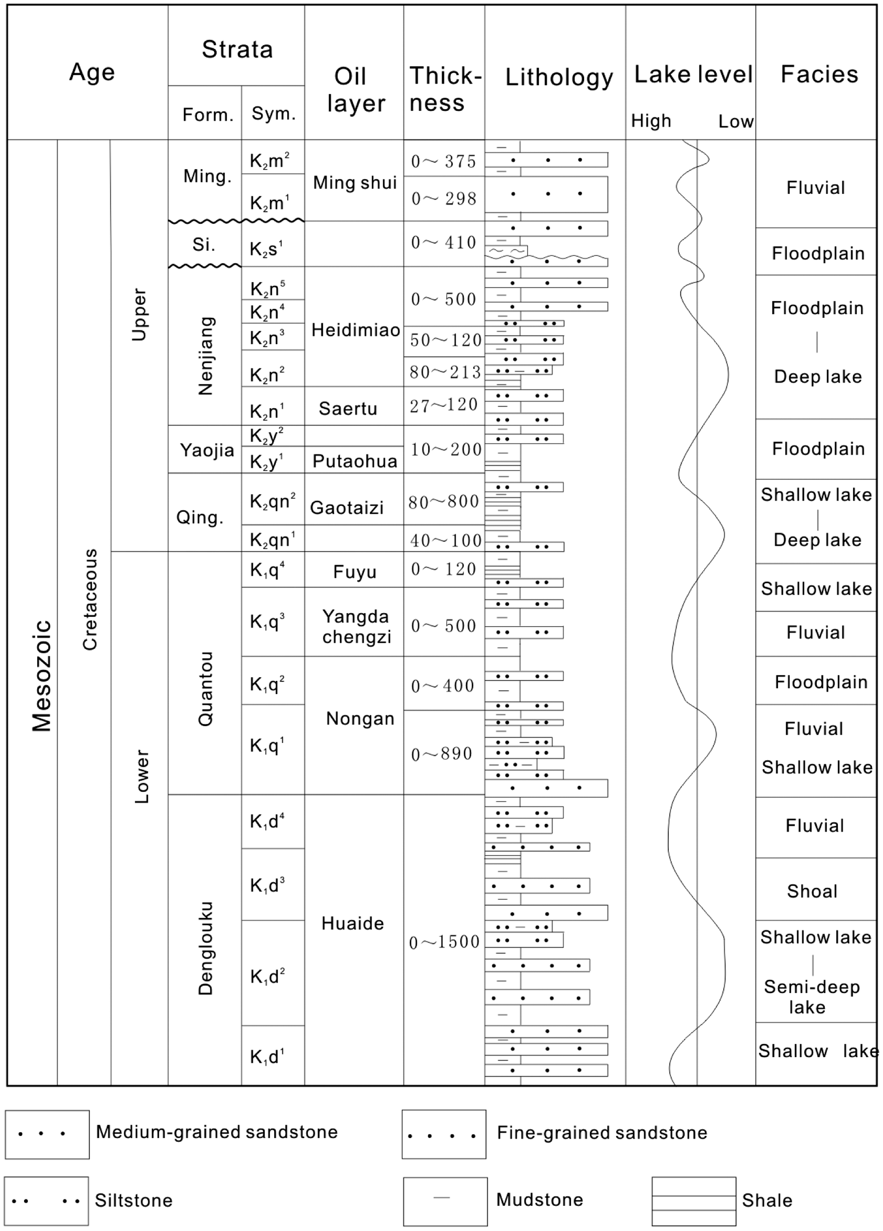
Fuyu oilfield is located on the eastern edge of the central sag area, Songliao Basin (Figure 1). Songliao Basin is a Mesozoic-Cenozoic continental petroliferous basin, which is composed of sub-fault basin and sub-depression basin (Xu et al., 2016). From bottom to top, the fault basin strata include middle and upper Jurassic, and the depression basin strata include Cretaceous, Neogene, and Quaternary (Mi et al., 2013; Xu et al., 2016). The Cretaceous is the main strata of the Songliao Basin and is divided into upper and lower systems. The lower Cretaceous, from bottom to top, is composed of Shahezi Formation (K1s), Yingcheng Formation (K1y), Denglouku Formation (K1d), and Quantou Formation (K1q). The upper Cretaceous, from bottom to top, is composed of Qingshankou Formation (K2qn), Yaojia Formation (K2y), Nenjiang Formation (K2n), Sifangtai Formation (K2s), and Mingshui Formation (K2m) (Ge et al., 2010). The main oil layers are the Quantou, Qingshankou, Yaojia, and Nenjiang Formations (Figure 2) (Ge et al., 2010; Wan et al., 2009). The target layer of Quantou Formation for oil exploitation is Fuyu oil layer (the fourth member of Quantou Formation), which is composed of typical shallow water delta sediments that mainly include siltstone and fine-grained sandstone with a lateral continuous reservoir distribution (Hu et al., 2008; Zhang et al., 2008).
(a) Map of China. (b) Fuyu structural oilfield (modified after Shu et al., 2003 with minor revisions). (c) Location of figures and well data used in this study. General stratigraphy of Fuyu oilfield showing lithology and sedimentary facies.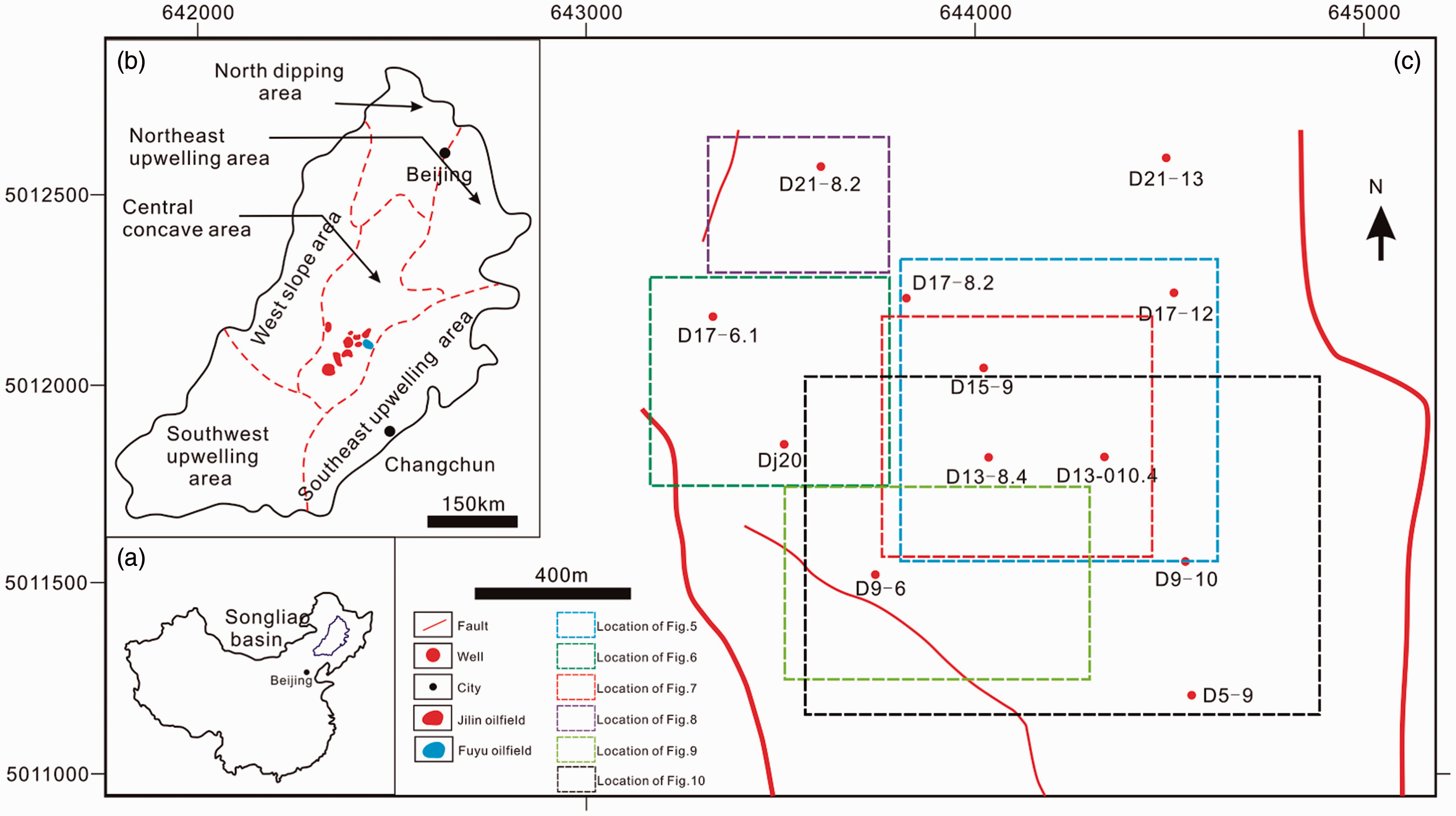
The sediments of Fuyu oil layer consist of quartz, feldspar, and rock debris. The average quartz content is 34.5% with a range of 21.3%–47.4%. The feldspar content is relatively high with an average of 48.6% and a range of 15%–60%, most of which is orthoclase. A large amount of the feldspar has been weathered to kaolinite. The average rock debris content is 16.9% with a range of 7.8%–50%, and it is mainly composed of igneous rock. The major cement is argillaceous cement with a small amount of calcareous cement. The average shale content is 18.5% with a range of 14.6%–24.7% (Sun et al., 2016).
Because oilfields are continuously developing, the study area is currently in the high water-cut exploitation stage. Therefore, its development is facing a serious and contradictory situation that is mainly characterized by the following considerations: (1) sand bodies exhibit large lateral variations, but there are limited numbers of in-depth studies on the effects of geometric shapes, internal structures, and 3D distributions of sand bodies on remaining oil; (2) the vertical distribution of reservoir is quite heterogeneous; high-permeability zones are easy to form water-flooded channels. Heterogeneous reservoirs lead to a relatively strong controlling effect on the distribution of remaining oil; (3) remaining oil has a rather complex distribution and is highly scattered, which leads to difficulties in studying the characteristics of remaining oil distribution; (4) because the well pattern is quite irregular in some regions, water flooding is not effective (Feng et al., 2012). Therefore, it is very possible that remaining oil is still present in these regions. Because of these problems, the distribution of remaining oil in the study area is not clear thereby making it difficult to carry out research.
Main factors controlling the distribution of remaining oil
Effect of micro-structures on the distribution of remaining oil
Researchers have paid increasing amounts of attention to the mechanisms by which micro-structures control the distribution of remaining oil (Ding and Lei, 2004; Hou et al., 2005). Authors have also analyzed the effect of micro-structures on the distribution of remaining oil and it has been found that even with micro-structure, sand body does not necessarily have remaining oil distribution (Figure 3(a)), even without micro-structure but with sand body may also have remaining oil distribution (Figure 3(b)). For example, suppose that within a layer, sand bodies A, B, and C are laterally stacked to form a composite sand body pattern as a result of the lateral migration of a river (Figure 3). A structure event occurs after the sedimentation of this layer; therefore, a positive micro-structure forms at point F and the structure is higher at point F than it is at point E and it is higher at point E than at point D, but remaining oil maybe distributed in sand body C which is higher than sand body A (Figure 3(a)), so even with micro-structure and sand body, point F (Figure 3(a)) does not necessarily have remaining oil distribution. If there is no structure event and the layer is relatively flat, although sand bodies A and B are water flooded, the remaining oil can be distributed in sand body C which is higher than sand bodies A and B (Figure 3(b)), so even without micro-structure in point D (Figure 3(b)), it can also have remaining oil distribution.
The mechanism of micro-structure and top surface of sand body on the distribution of remaining oil. (a) A positive micro-structure layer. (b) Flat layer.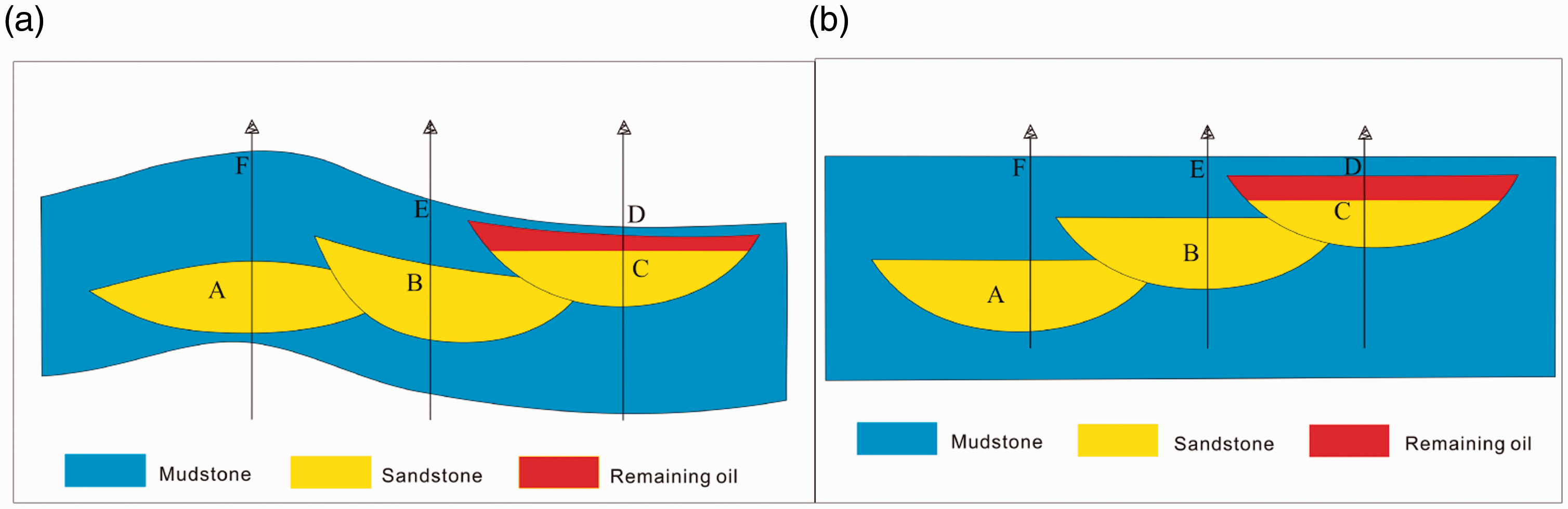
Therefore, only considering the structure of the strata is not enough in the study of positive micro-structure; the top surface of composite sand body in the layer should also be considered, that is to say the top surface of sand body is the key factor in controlling remaining oil distribution.
Effect of sedimentary micro-facies on the distribution of remaining oil
The reservoir of Fuyu oil layer is a typical shallow water delta front reservoir that includes five primary sedimentary micro-facies: subaqueous distributary channel, mouth bar, subaqueous natural levee, distal bar, and subaqueous interdistributary bay. Subaqueous distributary channel has the best physical properties; therefore, a dominant seepage channel is formed easily along the extension of subaqueous distributary channel. In contrast, the flank of subaqueous distributary channel has lower physical properties, which allows remaining oil to be distributed in localized regions. Mouth bar has better physical properties, and its permeability is mostly characterized by reverse or homogenous rhythm. The amount of water flooding is lower than the subaqueous distributary channel (Feng et al., 2012). Thin layers of remaining oil can easily accumulate on the top of the mouth bar. Subaqueous natural levee and distal bar have low physical properties, and remaining oil can accumulate in localized regions. The water flooding levels of Fuyu oil layer in the research area are: from highest to lowest, subaqueous distributary channel, mouth bar, subaqueous natural levee, and distal bar.
Effect of single sand body stacking on the distribution of remaining oil
The sand body stacking pattern is quite different for different stages of lake levels. The stacking of different sand bodies changes the connections and injection–production relationships between sand bodies, which increase the difficulty of researching the remaining oil. The sand body stacking pattern of Fuyu oil layer includes: separated, lateral stacking, multi-bed stacking, swing stacking, and isolated patterns (Feng et al., 2015) (Figure 4). Remaining oil is mainly distributed on the top of each sand body in separated pattern, (Figure 4(a)); the top of the late stage sand body in the lateral stacking pattern (Figure 4(b)); the top of the late stage sand body in the multi-bed stacking pattern (Figure 4(c)); on both sides of the composite sand body in the swing stacking pattern (Figure 4(d)); on the top of each sand body in the isolated sand bodies (Figure 4(e)).
The effect of single sand body stacking on the distribution of remaining oil.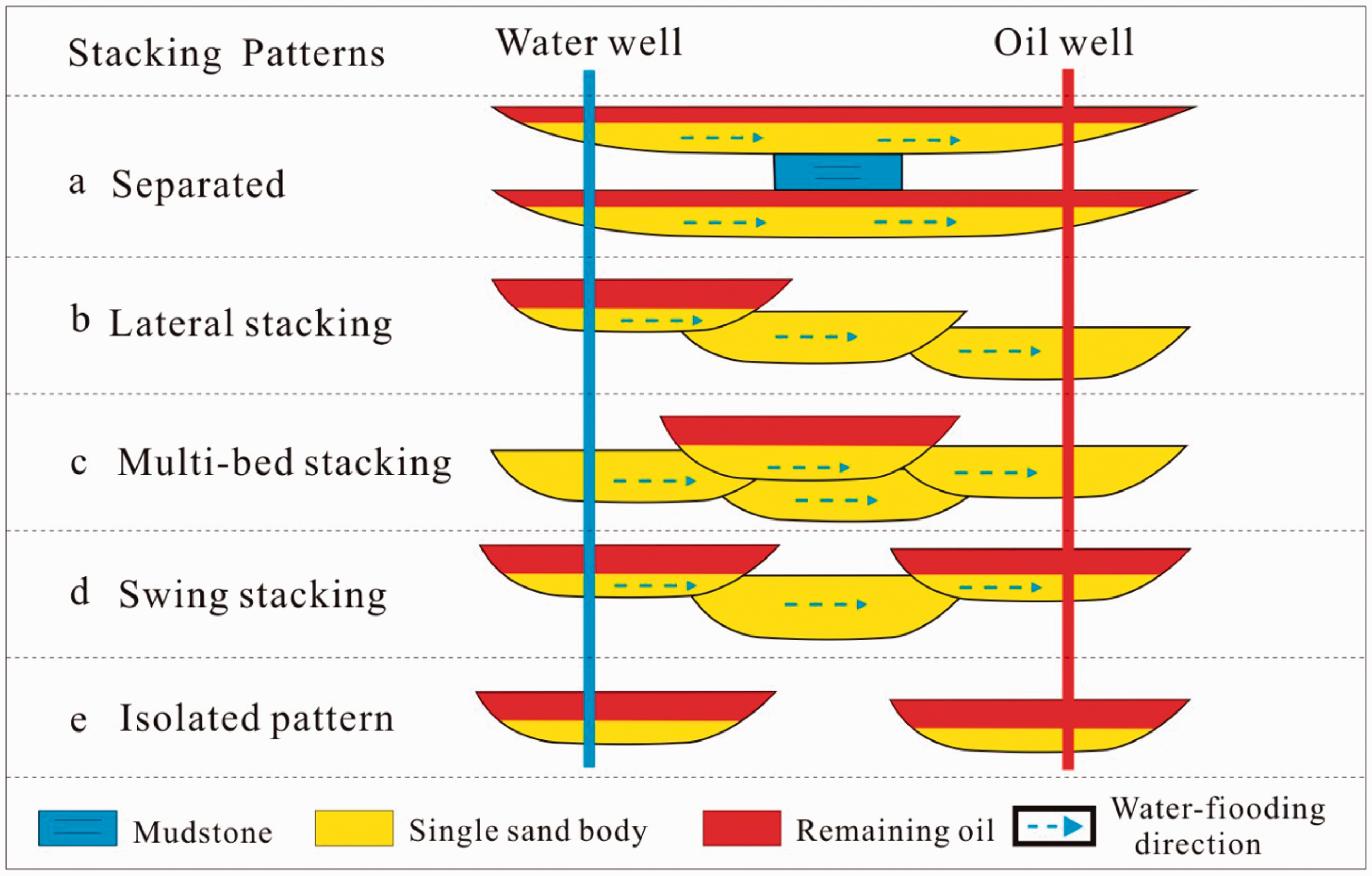
Effect of architecture elements on the distribution of remaining oil
The main architecture elements of single sand body in subaqueous distributary channels of Fuyu oil layer include foreset sand body (sandstone unit) and foreset (mudstone unit) (Feng et al., 2014). The controlling effects of foreset sand body and foreset on the distribution of remaining oil are quite different.
Effect of foreset on the distribution of remaining oil
Based on the damage degree of foresets, the foreset evolution in vertical direction can be divided into three types: remained foreset, destructive foreset, and mixed foreset (Figure 5). The remained foreset is at the lowest level of destruction and remains a certain thickness; the destructive foreset has been regionally or completely destroyed and regionally or not at all remained; the mixed foreset has a combination of the features of the previous two types.
The types of foreset in subaqueous distributary channel.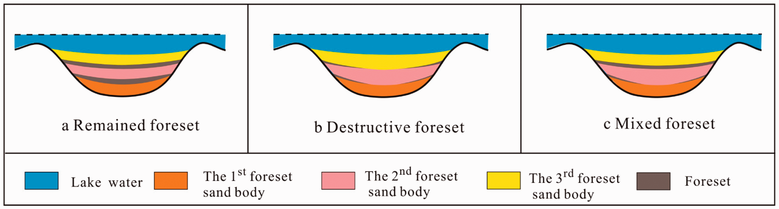
The barrier effect of remained foreset is the strongest because it can separate a thick sand body into several parts (foreset sand body) that have no or few vertical connections; remaining oil generally accumulates on the top of each foreset sand body. The barrier effect of destructive foreset is relatively low, and the sand bodies are vertically connected; therefore, remaining oil only accumulates on the top. Mixed foreset has the characteristics of both remained foreset and destructive foreset.
Effect of foreset sand body on the distribution of remaining oil
The stacking styles of foreset sand body in the study area can be divided into three types: progradation, retrogradation, and aggradation (Figure 6). Remaining oil mainly accumulates to a relatively high level in the updip direction of a progradation foreset sand body, and the injection–production relationship significantly impact its accumulation (Figure 6(a)). Remaining oil also mainly accumulates to a rather low level in the updip direction of a retrogradation foreset sand body, and the injection–production relationship also directly constrains its accumulation (Figure 6(b)). Remaining oil also accumulates in the updip direction of an aggradation foreset sand body, and the injection–production relationship directly constrains the level of its accumulation (Figure 6(c)).
The effect of foreset sand body on the distribution of remaining oil.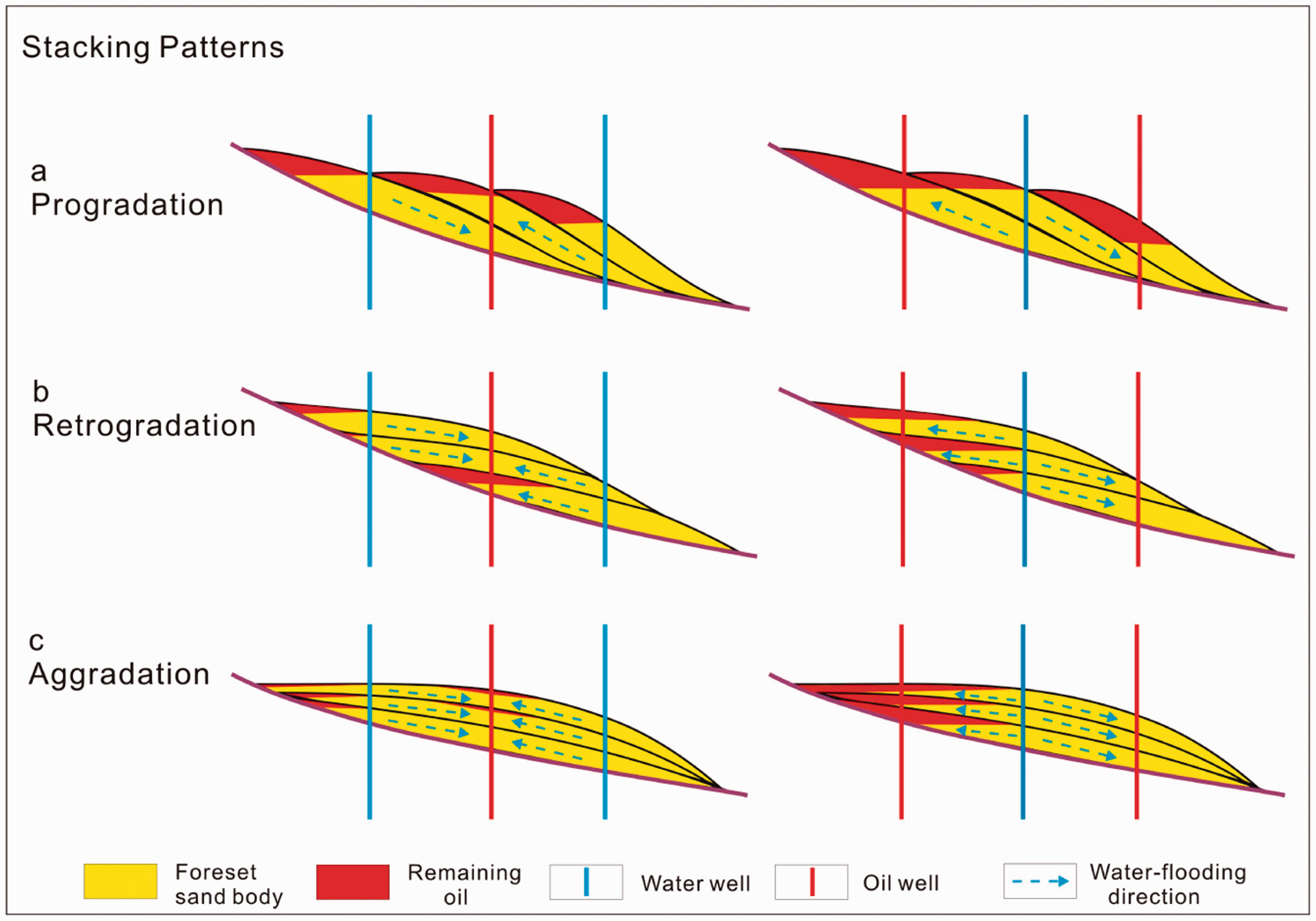
Effect of flow units on the distribution of remaining oil
The flow units in the subaqueous distributary channel of Fuyu oil layer can be divided into types E (excellent), G (good), M (medium), and P (poor). Type E is the best type of flow unit, its lithology including fine-grained sandstone, porosity greater than 28%, and permeability greater than 300 × 10−3µm2. Type G is the second type of flow unit, its lithology including fine-grained sandstone and siltstone, porosity is with a range of 25–28%, and permeability is with a range of 100–300 × 10−3µm2. Type M is the third type of flow unit, its lithology including siltstone, porosity is with a range of 22%–25%, and permeability is with a range of 30–100 × 10−3µm2. Type P is the worst type of flow unit, its lithology including argillaceous siltstone, porosity is lower than 22%, and permeability is lower than 30 × 10−3µm2.
The controlling effects of the different flow unit types on the distribution of remaining oil are quite different. The permeability of the type E flow unit is the highest, which allows dominant seepage channels to form easily. Therefore, remaining oil rarely accumulates in type E flow units. Type P flow units are generally impermeable and, therefore, provide effective impermeable barrier layers. Different types of flow units combine in different patterns that have varying rhythmic characteristics, which lead to different remaining oil distributions: when the rhythmic flow unit combination pattern is positive (M–G–E), remaining oil is mainly distributed on the top; when it is reversed (E–G–M), the water-flooding level is quite high, and generally, no remaining oil accumulates.
Importance of multi-factor coupling for predicting remaining oil
The distribution of remaining oil is affected by a number of factors, which can be divided into two categories: geological and engineering factors. Geological factors include micro-structure, faults, sedimentary micro-facies, reservoir heterogeneity, sand body stacking patterns, and reservoir architecture. Engineering factors include well patterns, injection–production relationships, and production dynamics. Therefore, there is limitation in the analysis of the distributions of remaining oil using only a single factor. The next example will show that using a multi-factor coupling analysis is necessary in the research area.
Large areas of subaqueous distributary channels are developed in the area of well D15-9 in the seventh layer (Figure 7(a)). Using quantitative characterizations of single sand body (Feng et al., 2015), the authors found that the second and third single sand body were clearly laterally stacked in this area; the top surface of the third single sand body was higher than that of the second single sand body (Figure 7(b) and (d)). By overlapping with the contour lines of micro-structure in this area, a positive micro-structure can be found between wells D15-9 and D13-8.4 with a closure height difference of 4 m (Figure 7(c)). Because the top surface of the third single sand body was clearly higher than the second one, it can be concluded that remaining oil is more likely to accumulate in the positive micro-structure region of the third single sand body and cannot accumulate in the positive micro-structure region of the second single sand body (Figure 7(c)). Therefore, analyzing the coupled effects of positive micro-structure, sedimentary micro-facies, and single sand body stacking on the distribution of remaining oil has more effect than analyzing only on the sedimentary micro-facies.
Multi-factor coupling in well D15-9 in the seventh layer. (a) The diagram of sedimentary micro-facies. (b) The diagram of single sand bodies. (c) The diagram of single sand bodies and its micro-structure. (d) The section of single sand bodies.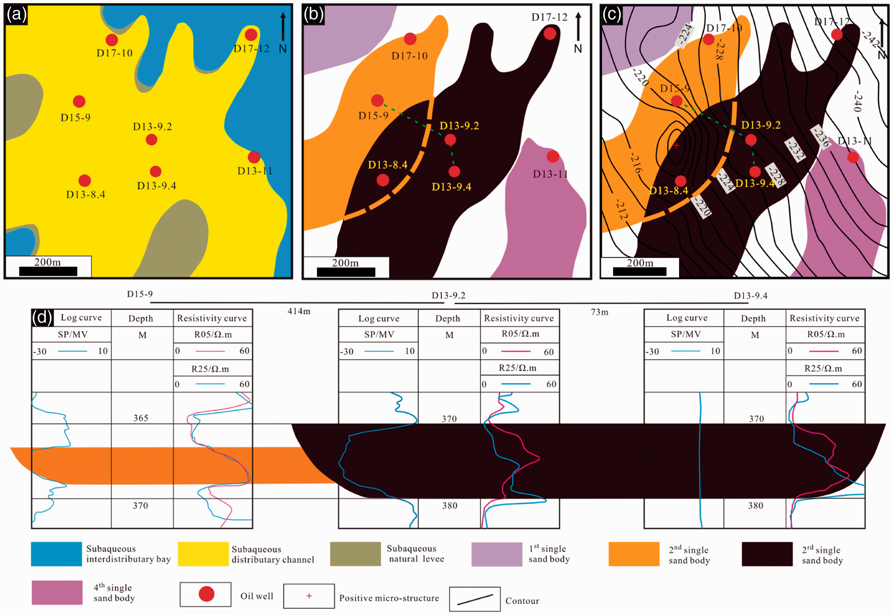
A predictive model for the remaining oil based on the effects of multi-factor coupling
Guided by research on the effect of multi-factor coupling, the authors analyzed the effects of micro-structures, sedimentary micro-facies, single sand body stacking, architecture elements, flow units, well patterns, and injection–production relationships on the distribution of remaining oil in the study area to identify key controlling factors, and established five kinds of predictive models for remaining oil accumulation.
Model based on the coupled effects of micro-structures, sedimentary micro-facies, and injection–production relationships
The remaining oil accumulation model based on the coupled effects of micro-structure, sedimentary micro-facies, and injection–production relationships are a typical pattern in fault oilfield. In the middle development stage of Fuyu oilfield, the subaqueous distributary channel of the delta front is the primary micro-facies, as the later development stage of the oilfield, subaqueous distributary channel sand body easy to form dominant seepage channel because of good connectivity and high permeability, it lead to the remaining oil difficult to enrich. As the micro-structure theory been put forward and through the study on the micro-structure water-flooding mechanism, it was found that some subaqueous distributary channels controlled by positive micro-structure may lead to the enrichment of remaining oil.
Large areas of subaqueous distributary channel sand bodies are developed in the area of well D15-06.4 in the seventh layer. By stacking the micro-structure and sedimentary micro-facies, it is found that there is a positive micro-structure and its closure difference about 4 m in the area of well D15-06.4. Well D15-5.2 in this area is injection water well, and the distance between well D15-5.2 and D15-06.4, D15-05.4, D17-6.4, D17-6.1, respectively, is 136 m, 219 m, 346 m, and 339 m (Figure 8). By single well remaining oil interpretation found that the remaining oil saturation of well D15-06.4 and well D15-05.4, respectively, is 45% and 25%.
The model of remaining oil accumulation based on the coupled controlling effects of micro-structure, sedimentary micro-facies and injection–production relationships.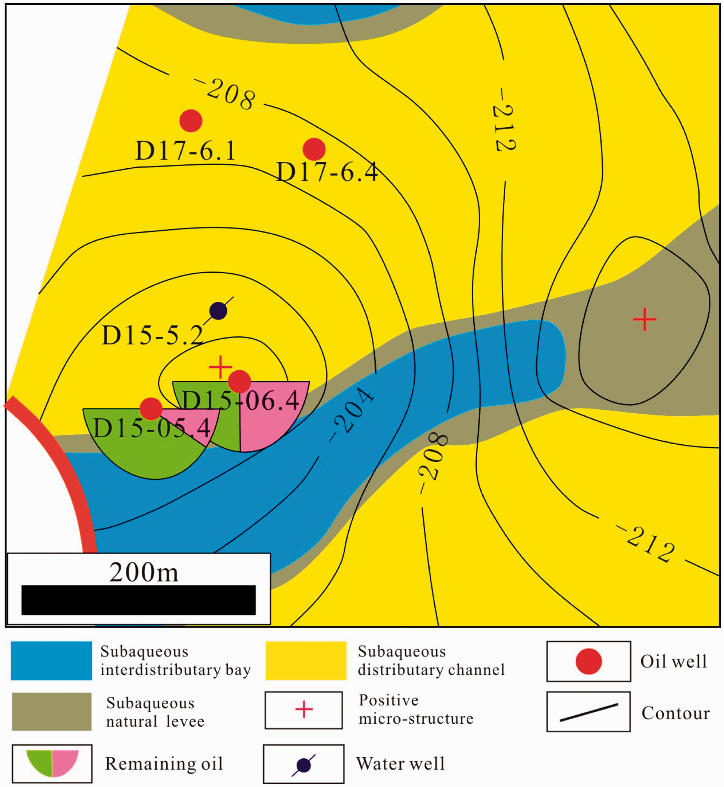
From this example, it can be found that remaining oil can accumulate in this positive micro-structure, and there are three reasons that can lead to remaining oil enrichment: (1) the subaqueous distributary channels have good porosity and permeability; (2) obvious positive micro-structure characteristics; (3) the injection–production relationship between well D15-5.2 and well D15-06.4; well D15-05.4 is in the reverse paleocurrent direction, water flooding is difficult, injection water easily flows through the path along the paleocurrent direction.
Model based on the coupled effects of micro-structures, sedimentary micro-facies, single sand body stacking
The remaining oil accumulation model based on the controlling effects of micro-structure, sedimentary micro-facies, single sand body stacking is concerned with the different stages of single sand body stacking which lead to different elevations on the top surface of the composite sand body; when the injection–production well spacing is greater than the size of the late-stage sand body, it is easy to accumulate the remaining oil on the top of the late-stage sand body.
Large areas of subaqueous distributary channel sand bodies are developed in the area of well D15-09.4 in the seventh layer, and there are four single sand bodies in this area. The third single sand body has a clear cut effect on the second single sand body (Figure 9). By overlapping with the micro-structure contours for the top plane of layer, it is found that the area was with an apparent positive micro-structure and a closure height difference of 4 m near oil well D15-09.4. Water-injection wells D+13-8.2 and D+13-7.2 were drilled outside of the area of this micro-structure. By single well remaining oil interpretation found that the remaining oil saturation of well D15-09.4 is 44%, but the remaining oil saturation of wells D13-7.4, D13-09.4, and D13-010.4 were all relatively low, with values of 20%, 17%, and 28%, respectively. Therefore, in the area with normal micro-structures and stacked single sand bodies, a large amount of remaining oil accumulates (Figure 9).
The model of remaining oil accumulation based on the coupled effects of micro-structure, sedimentary micro-facies, single sand body stacking. The model of remaining oil accumulation based on the coupled effects of secondary micro-facies, flow units and well patterns.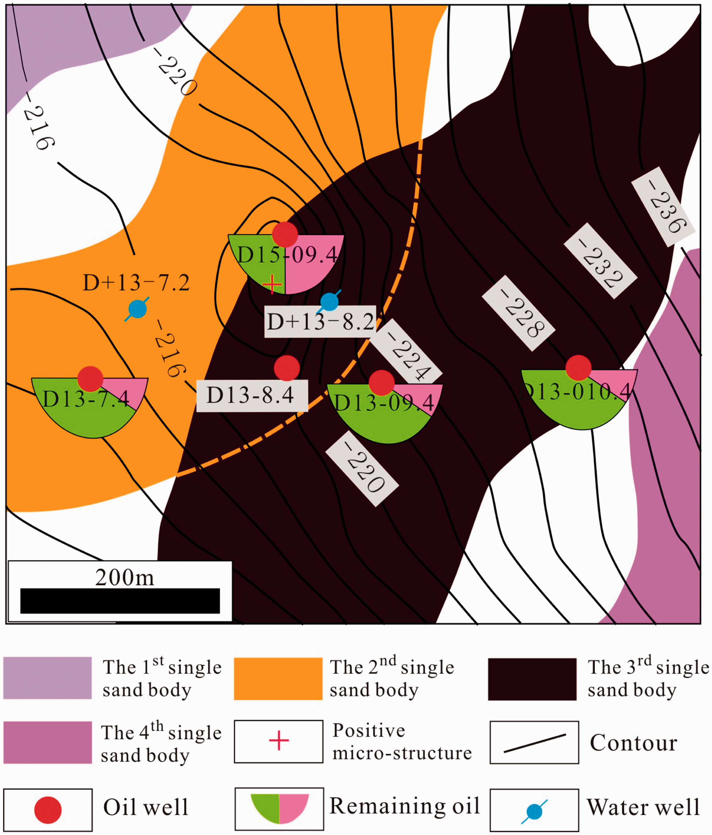
Model based on the controlling effects of secondary micro-facies, flow units, and well patterns
The remaining oil accumulation model based on the controlling effects of secondary micro-facies, flow units, and well pattern is concerned with the remaining oil that accumulates in subaqueous natural levee or distal bar. During the developmental stage of the oilfield, the oil in the main facies, such as subaqueous distributary channel, has been exploited. The lateral heterogeneous reservoir leads to the accumulations of remaining oil in subaqueous natural levee and distal bar with low porosity and permeability, which become important because of their potential to increase oil production and preservation in the late stage of maturing oilfield’s development.
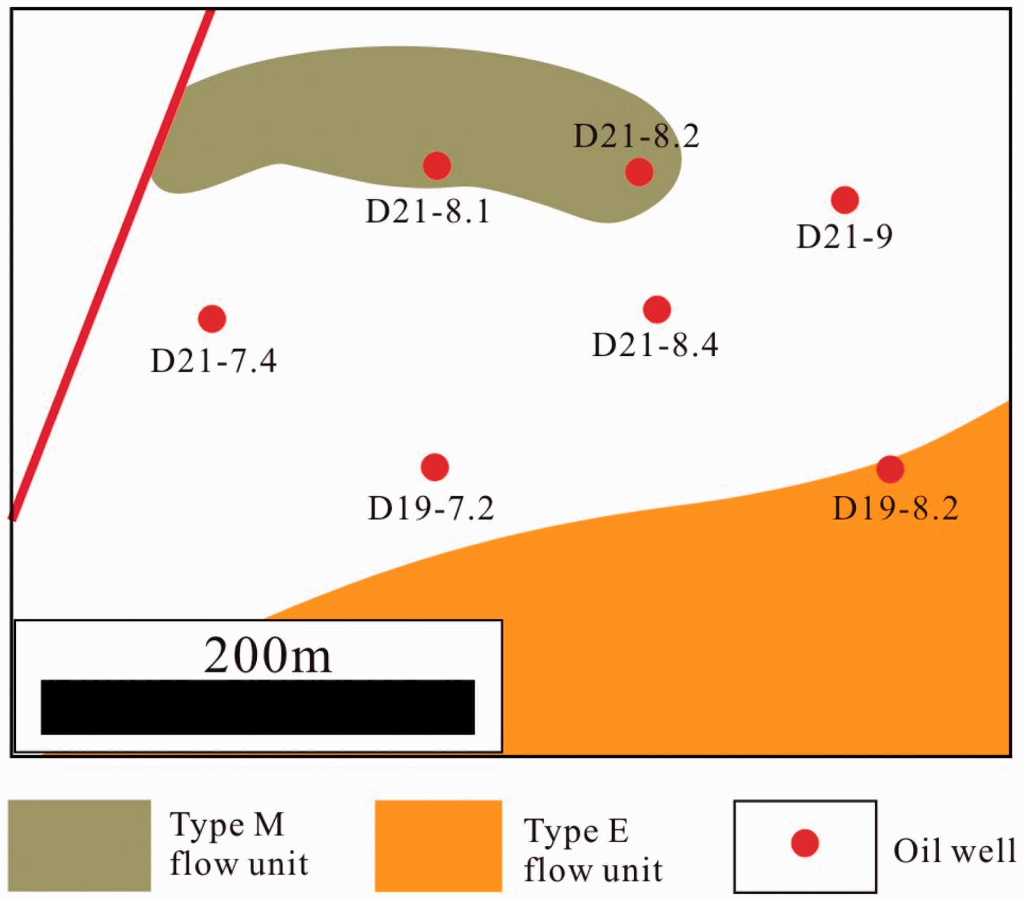
Well D21-8.1 is a distal bar in the northwestern corner of the eighth layer in study area. The sand body is a type M flow unit, which is able to reserve certain amounts of oil. Three oil wells are located in this sand body, but there is no water-injection well (Figure 10). Therefore, this sand body has a well pattern that is characteristic of “production without injection,” and this type of single sand body signals a potential area for remaining oil.
Model based on the coupled effects of sedimentary micro-facies, single sand body, flow units, and injection–production relationships
The remaining oil accumulation model based on the coupled effects of sedimentary micro-facies, single sand body, and injection–production relationship is concerned within the same sedimentary micro-facies and same single sand body, the flow units are of a high-level type and have good amounts of oil. However, if the injection–production well pattern is not matched, this type of single sand body signals a potential area for remaining oil.
The third single sand body in the eighth layer is a branch of the subaqueous distributary channel; the top surface structure is characterized as a homocline from east to west (from low to high). The front of the sand body is a type P flow unit whose porosity and permeability is low. Near well D9-6, there is a type G flow unit that is characterized by high porosity and permeability and has a potential of reserving oil. Within this single sand body, there are five oil wells: D9-5.2, D9-6, D9-6.2, D9-6.4, and D9-7.4. Outside of this single sand body, there is mudstone sedimentation, which belongs to subaqueous interdistributary bay. There is no water-injection well in the single sand body, which is typical of the “production without injection” well pattern. Therefore, this type of single sand body signals a potential area for remaining oil (Figure 11).
The model of remaining oil accumulation controlled by the coupled effects of sedimentary micro-facies, single sand body, flow units and injection–production relationship.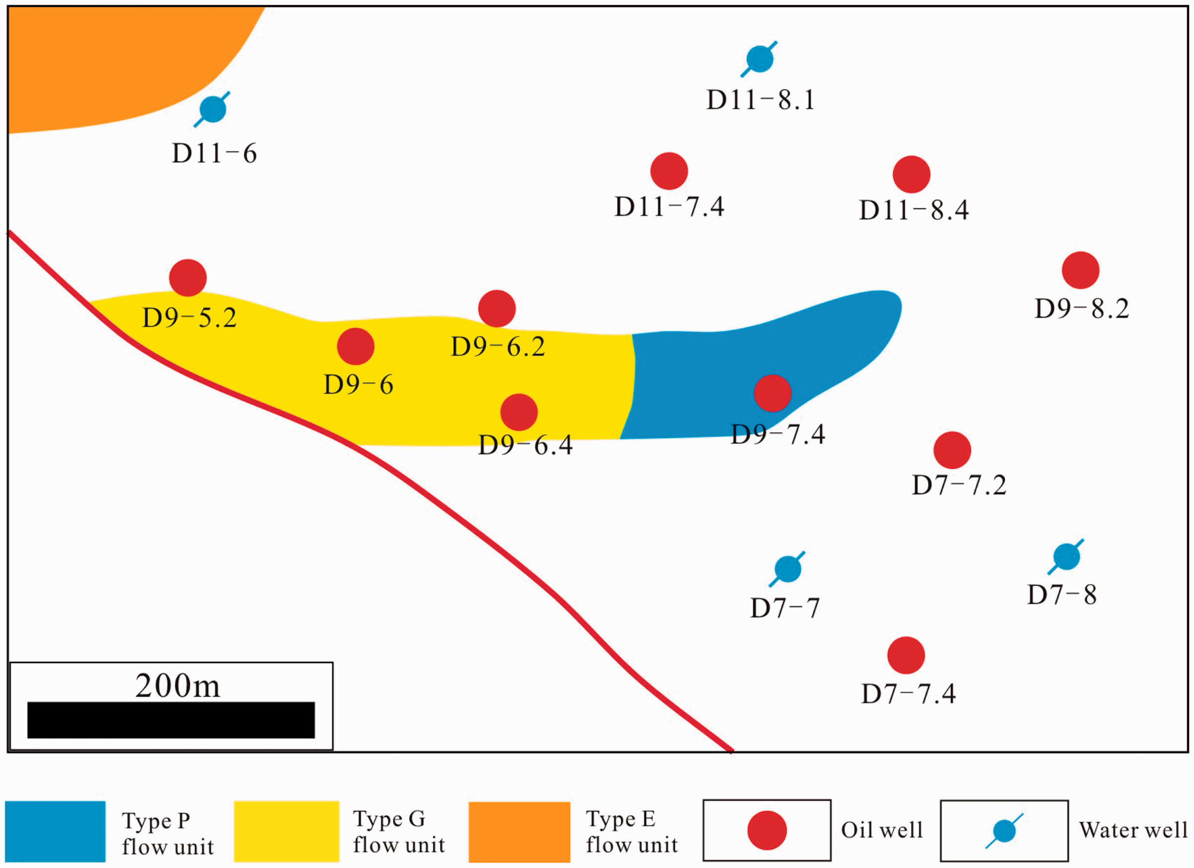
Model based on the coupled effects of sedimentary micro-facies, reservoir architecture, flow units, and injection–production relationship
The remaining oil accumulation model based on the coupled effects of sedimentary micro-facies, reservoir architecture, flow units, and injection–production relationship is concerned that because of the barrier effect of foreset, the different stacking patterns of foreset sand bodies, and the different distribution characteristics of flow units, there is significant heterogeneous in each single sand body of subaqueous distributary channel; therefore, when the injection–production relationship is different, the amount of remaining oil accumulated is also different.
The top surface structure of the third single sand body of the sixth layer is homocline; from southwest to northeast, the structure contour gradually decreases. The single sand body is mainly vertically stacked by two different foreset sand bodies. During the sedimentary stage, the lake level gradually rose; therefore, the second foreset sand body is clearly stacked retrograded on the first foreset sand body. In addition, those two foreset sand bodies are more laterally shifted, and the foreset between these two foreset sand bodies were completely destroyed, which leads to better vertical connections within the two foreset sand bodies.
Flow units of types E, G, M, and P are developed on the second foreset sand body; from southwest to northeast, and the quality of the flow units gradually decreases (Figure 12(b)). Type E flow unit in the second foreset sand body near the fault is the best reservoir. Because only water-injection wells D7-7, D7-8, and D11-11 are within this foreset sand body, in particular, oil wells D9-6, D9-6.4, D7-6.2, and D7-6.4 are located in the updip direction of the foreset sand body, it cannot form an effect injection–production relationship with water-injection well D7-7. According to single well remaining oil interpretation, the remaining oil saturation of wells D9-6.4, D7-6.2, and D7-6.4 are, respectively, 31%, 21%, and 54%. In the updip direction of the second foreset sand body, large amounts of remaining oil accumulate (Figure 12(a)).
The remaining oil accumulation model based on the coupled effects of sedimentary micro-facies, reservoir architecture, flow units, and injection–production relationship. (a) The distribution of flow units and remaining oil in the second foreset sand body. (b) The distribution of flow units in the first foreset sand body.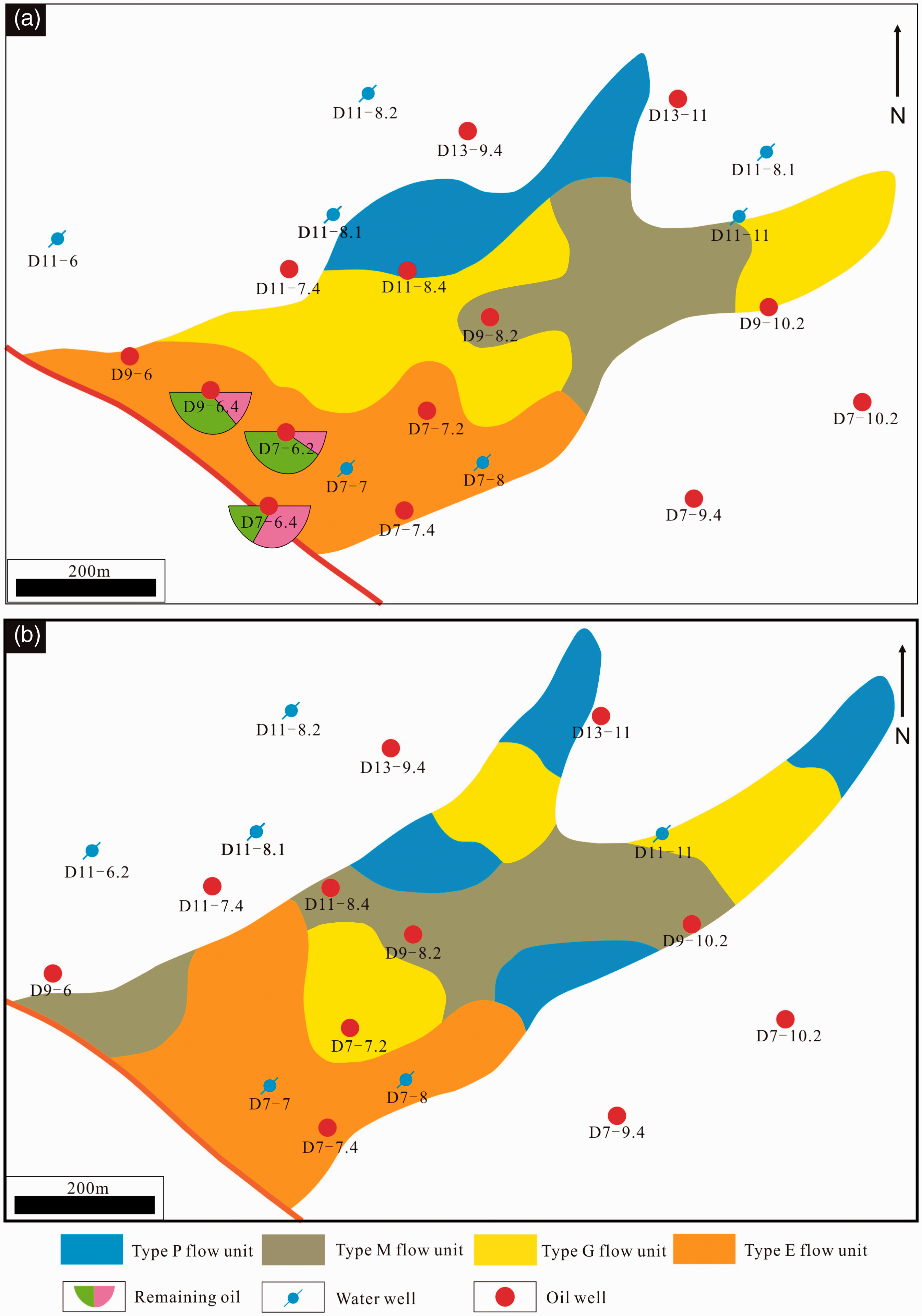
Controlling effect of geological factors on the distribution of remaining oil
The distribution of remaining oil is affected by a number of factors, which include both geological and engineering factors. By controlling the micro-structure, the remaining oil is mostly distributed in the positive micro-structure, and the top surface of sand body is key factor on the distribution of remaining oil. The water flooding levels for oil are quite different in different sedimentary micro-facies. In general, it is easier to drive oil in highly porosity and permeability micro-facies; in contrast, micro-facies with low porosity and permeability accumulate remaining oil more easily. The higher the stacking of single sand bodies, the better connection within the sand bodies. In addition, remaining oil is generally distributed in the top of stacked sand bodies but is also affected by the distribution of mudstone interlayers within the sand bodies. The scale, tilt angle, and tilt direction of architecture elements also significantly affect the distribution of remaining oil. The stacking pattern and distribution of flow units affect the remaining oil distribution. Therefore, it is effective to establish a model of the remaining oil distribution by considering the coupled effects of multiple factors.
Conclusions
The distribution of remaining oil is affected by a number of factors. The top surface of sand body is one of the key factors in controlling the distribution of remaining oil. The water-flooding levels of sedimentary micro-facies, from highest to lowest: subaqueous distributary channel, mouth bar, subaqueous natural levee, and distal bar. Different stacking types of single sand bodies have a strong controlling effect on the distribution of remaining oil, and the remaining oil is mainly distributed on the top of the late stage stacking sand body. On the basis of analyzing multiple controlling factors, and identified key controlling factors, five models for the distribution of remaining oil were established by using the coupled effects of multi-factors method: model one that includes micro-structure, sedimentary micro-facies and injection–production relationship; model two that includes micro-structure, sedimentary micro-facies, single sand body stacking; model three that includes the secondary micro-facies, flow units, and well pattern; model four that includes sedimentary micro-facies, single sand body, and injection–production relationship; and model five that includes sedimentary micro-facies, architecture elements, flow units, and injection–production relationship.
Footnotes
Acknowledgements
The authors would like to thank the anonymous reviewers for their critical reviews.
Declaration of conflicting interests
The author(s) declared no potential conflicts of interest with respect to the research, authorship, and/or publication of this article.
Funding
The author(s) disclosed receipt of the following financial support for the research, authorship, and/or publication of this article: This study was supported by National Natural Science Foundation of China (No. 41502127), MOST Special Fund from the State Key Laboratory of Continental Dynamics, Northwest University, Scientific Research Program Funded by Shaanxi Provincial Education Department (No. 14JK1754) and Postdoctoral Program Funded by China (No. 2015M572594).