
Abstract
This study deals with mathematical modeling and energy analysis of an ice rink cooling system with an underground thermal energy storage tank. The cooling system consists of an ice rink, chiller unit, and spherical thermal energy storage tank. An analytical model is developed for finding thermal performance of the cooling system. The model is based on formulations for transient heat transfer problem outside the thermal energy storage tank, for the energy needs of chiller unit, and for the ice rink. The solution of the thermal energy storage tank problem is obtained using a similarity transformation and Duhamel superposition techniques. Analytical expressions for heat gain of the ice rink and energy consumption of the chiller unit are derived as a function of inside design air, ambient air, and thermal energy storage tank temperatures. An interactive computer program in Matlab based on the analytical model is prepared for finding hourly variation of water temperature in the thermal energy storage tank, coefficient of performance of the chiller, suitable storage tank volume depending on ice rink area, and timespan required to attain an annually periodic operating condition. Results indicate that operation time of span 6–7 years will be obtained periodically for the system during 10 years operating time.
Introduction
Imagination of a prosperous sustainable society without smart energy strategies seems impossible. While the amount of world energy consumption increases nonstop, there are only two solutions to avoid the fatal consequences: producing energy more sustainably and using the produced energy more efficiently. While there are big efforts to use renewable energies, it seems that still there is a long way to go and the dominating resources are still nonrenewable energies. Keeping this in mind, using this energy more efficiently is the best answer to problems followed by enormous energy consumption (Karampour, 2001). With it, much more consumption of fossil fuels causes increasing of CO2, SOx, and NOx emissions to the atmosphere as well as fossil fuels importing for developing countries (Novo et al., 2010; Saidur, 2010). For these reasons, many governments have decided to strengthen their national efforts to increase the deployment of energy conservation technologies and increase the utilization of renewable energy sources (Novo et al., 2010). In addition to these, the number of sports facilities is increasing day by day, especially in developing countries, to improve public health. Examples of these include sports facilities such as ice skating rinks, swimming pools, basketball courts, and volleyball courts. Specially, ice skating rinks are widely used for hockey, curling, figure skating (Kuyumcu et al., 2016). On an ice skating rink, the ice temperature should be maintained between −6 and −1℃, and cooling should be provided by circulating saline solutions in tubes or tubes to ensure that the ice surface has a required hardness for different types of ice sports (IIHF, 2015). Excess energy from the ice rink is rejected from the condenser of a chiller unit into the environment as waste energy by using conventional air source chillers (Işbilen, 1993; Khalid and Rogstam, 2013; Seghouani et al., 2011). Furthermore, the instantaneous change in air temperature can cause irregularity of the system performance (coefficient of performance (COP)) and conventional air source chillers work at low COP values when the weather temperature is high in summer. However, a ground couple chiller, which uses the buried thermal energy storage (TES) tank in the ground as a heat exchanger, can operate at more stable COP values. This is because the ground temperature does not fluctuate greatly during the whole year. It can be easily seen that underground TES tank can be a viable solution for saving the waste energy from the chiller unit.
There are several experimental and analytical studies concentrating on the design, analysis, and optimization of TES and ice rink. Dincer (2002) dealt with the methods and applications of describing and assessing and using TES systems, as well as economical, energy conservation, and environmental aspects of such systems. Zogou and Stamatelos (1998) investigated the effect of climatic conditions on the performance of heat pump systems for space heating and cooling and concluded that warmer Mediterranean climatic conditions are well suited for these applications. Petit and Meyer (1997) studied techno-economic comparison of air source and horizontal ground source air-conditioning systems in South Africa. They reported that the capital cost is higher in ground source system while the running cost is higher in air source system. Nikajima et al. (1982) analyzed the temperature field in the earth in the cylindrical coordinate system and predicted heat transfer of tube inside earth can move from an indoor space. Rismanchi et al. (2013) developed a computer model to determine the potential energy savings of implementing cold TES systems in Malaysia. They found that the overall energy usage of the cold TES storage strategy is almost 4% lower than the nonstorage conventional system. Kizilkan and Dincer (2015) presented a comprehensive thermodynamic assessment of a borehole TES system for a heating case at the University of Ontario Institute of Technology. They performed energy and exergy analyses based on balance equations for the heating application. COPHP and overall exergy efficiency of the studied system are calculated as 2.65 and 41.35%, respectively. Zhang et al. (2007) analyzed a model of a space heating and cooling system of a surface water pond that has an insulating cover, which serves as the heat source in the winter and heat sink in the summer. They considered three running modes to analyze the interaction of the seasonal heat charge and discharge for heating and refrigeration individually.
Yumrutas and Unsal (2000) proposed a computational model for the analysis of ground-coupled heat pump space heating system with a hemispherical storage tank as the ground heat source.
Previous studies about an ice rink, Bellache et al. (2005) made a 2D numerical simulation using a k−ɛ turbulence model for a ventilated ice skating rink. They investigated the heat and mass transfer on the wall and roof of the ice rink and found the convection and radiation heat fluxes on the ice rink. Caliskan and Hepbasli (2010) analyzed the ice rink building at varying reference temperatures whose study deals with energy and exergy analyses of ice rink building. Shahzad (2006) has examined the pipe material and its dimensions by optimizing the heat transfer and pressure drop by using CO2 as the secondary refrigerant circulated in the cooling system of the ice rink.
In this study, an analytical and computational model for an ice rink cooling system with an underground TES tank is developed. The analytical model consists of periodic solutions of transient heat transfer problem outside of the TES tank, expressions for ground-coupled chiller unit and for the ice rink. An interactive computer program in Matlab is prepared to investigate effects of water and ambient air temperature, earth type, Carnot efficiency (CE) ratio, storage tank size and ice rink area on the chiller COP, and to find timespan required to attain an annually periodic operating condition. Results obtained from the computational program are given as figures and discussed in the study.
Description of the cooling system
TES is a low cost, high impact in the storage technologies (Ozisik, 1985). There are many storage technologies, such as electric battery storage, which are often prohibitively expensive for large-scale applications. Nevertheless, TES is a simple technology for storing thermal energy by heating and/or cooling a material and/or space which is called the storage medium. Use of underground TES tank in cooling system has many advantages. Since less work will be used by the compressor, COP of chiller increases, size of chiller to be used will decrease, and then investment cost decreases indirectly. Therefore, use of underground TES tank is proposed from these considerations. Schematic representation of the cooling system is shown in Figure 1. The cooling system has three components, which are an underground TES tank, chiller unit, and an ice rink to be cooled in whole year.
Ice rink cooling system with an underground TES tank. TES: thermal energy storage.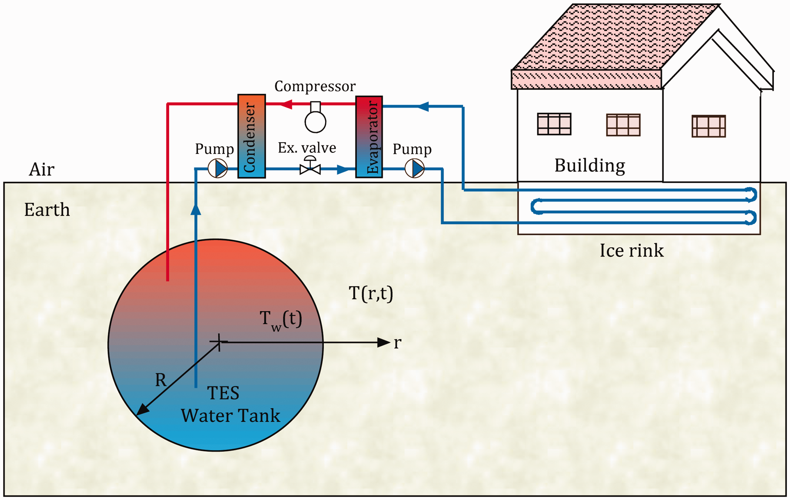
The most important component of the cooling system is the underground TES tank which provides energy savings and contributes to reductions in environmental pollution (Novo et al., 2010). Energy is transferred from the condenser to water in the TES tank. This energy flows through the ground, which decreases water temperature rapidly. The ground is used as large energy storage medium with large mass and stable temperature (De Swardt and Meyer, 2001; Yumrutas and Unsal, 2000). The energy exchange between condenser of the chiller unit and the ground will improve performance of the cooling system. Therefore, the TES tank or ground surrounding the tank will have positive effects on performance of the cooling system. The TES is considered to be spherical in shape and buried under ground. It is assumed that water is to be used as a storage medium in the tank due to high specific heat of water and high capacity rates for thermal charge and discharge. The higher heat capacity and lower cost of water often makes the water as an appropriate choice for TES systems (Yumrutaş et al., 2005).
The chiller unit is another important part of system, which is coupled to the TES tank and ice rink. The ground-coupled chiller technology can achieve higher energy efficiency for space cooling than conventional cooling because the underground environment provides lower temperature for cooling and experiences less temperature fluctuation than ambient air temperature variations (Yumrutas and Unsal, 2012). Main components of the chiller unit are known as evaporator, compressor, condenser, and expansion device. Refrigerant circulated in the chiller unit extracts energy through the evaporator from the ice rink, and it is compressed by the compressor to the condenser to reject heat to the water in the storage tank.
Modeling of the cooling system
The ice rink cooling system is shown schematically in Figure 1. The cooling system consists of three main components. In order to obtain mathematical modeling of the cooling system, it is necessary to make thermal analysis of each component of the system. For that reason, the thermal analysis of each component of the system is presented in this section. This model is developed for the determination of water temperature in the TES tank, the heat rejected from ice rink, COP of the chiller unit for given cooling requirements of the ice rink, and climatic conditions for the location. Temporal variation of water temperature in the TES and inside surrounding earth are determined by solving of the transient heat transfer problem outside the tank. The solution procedure for the TES tank problem, expressions for the chiller unit, and ice rink are presented in this section.
Transient heat transfer problem around the TES tank
It is assumed that the TES tank is spherical in shape and filled with water. The water is considered to be initially at the deep ground temperature T∞, and fully mixed at a spatially lumped time varying temperature Tw(t). The TES tank is assumed to be located deep enough so that the far field ground temperature away from the storage is taken to be constant and equal to the deep ground temperature, T∞. Earth surrounding the tank is assumed to have homogeneous structure and constant thermophysical properties. In this section, an expression will be determined for finding the water temperature in the TES tank as a function of time.
Transient temperature field problem inside the earth of outside the spherical TES tank and its initial and boundary conditions are given in spherical coordinates as follows


The energy transferred to the tank is equal to the difference between sensible energy increase of the tank and the conduction heat loss from the tank to the surrounding earth. This is expressed as

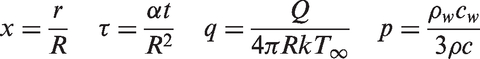


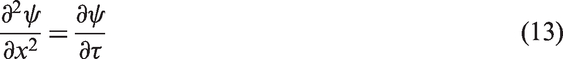
The dimensionless formulation of the problem given by equations (7) to (11) is further simplified by an application of the following transformation


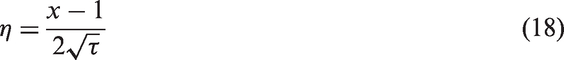
When the following similarity transformation variable η

The dimensionless transient temperature distribution in the earth surrounding the TES tank is obtained using Duhamel’s superposition technique, which is given by the following expression

If the solution for φ is now differentiated with respect to the dimensionless variable x, the result evaluated at x = 1 and substituted into equation (17), the following integro-differential equation is obtained

Equation (21) can be discretized and solved for the dimensionless temperature of the water in the TES tank at the nth time increment to yield
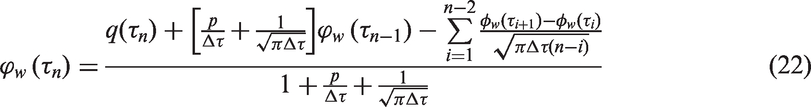
Equation (22) will be used to calculate the water temperature of the spherical TES. The term q(τ) in equation (22) represents the dimensionless net heat input rate to the TES tank. The heat input rate to the TES tank,

Energy analysis of the ice rink
Energy analysis of the ice rink is made in this section. First, energy requirement for making ice sheet which is named as precooling load, and then second, operating cooling load is very important part of total cooling load after working of ice rink. Therefore, calculation of precooling load and operating cooling load is to obtain the total cooling load of the ice rink.
Precooling requirement
Expressions for water chilling and freezing, concrete chilling and refrigeration to cool by secondary coolant loads are given in this section. Water chilling and freezing load, QF is calculated from


Operating cooling requirement
Operating cooling load,


Lighting is a major source of radiation heat to the ice sheet. The direct radiant heat component of the lighting can be 60% of the rating of the luminaries (ASHRAE, 2006). Heat load of the luminaries, Qlump is taken to be 0.0182Arink. Radiation heat component of the lighting, Qlight can be expressed by

Radiation heat load, QR is

Heat gains due to conduction,


Heat gain from skating people,

Total of heat gain due to conduction is expressed by

Operating cooling load,

Total cooling load, QL is the sum of the precooling load (

Energy requirement of the ice rink
Energy demands of the ice rink may be expressed as a function of ambient air temperature which changes with time. Instantaneous energy demands of the ice rink in the whole years may be expressed as


Energy requirement of the chiller unit
The chiller unit used in the cooling system absorbs heat in the ice rink and supplies heat to the underground TES tank. Cooling load for the ice rink can be represented by the product of the COP of the chiller and chiller’s compressor work

COP of the heat pump may be expressed as


When equations (44) and (48) are inserted into equation (46), the dimensionless compressor work may be expressed as

The parameter u in equations (48) and (49) is defined as

Computational procedure
A computer program in Matlab based on the present analytical model was prepared to carry out the numerical computations. The computational procedure was used to find the temporal variation of water temperature in the TES tank and other performance parameters such as the COP of the chiller and the annual energy fractions. The program uses an iterational procedure to calculate these parameters at nearly 10 years. Our program is working nearly 25 min at special computer properties which have 6 GB RAM and 2.6 GHz microprocessor.
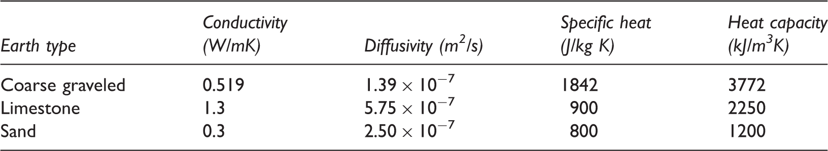
Properties of the geological structures (Ozisik, 1985).
The initial storage temperature is assumed to be equal to the deep ground temperature in the start of the computations. The deep ground temperature is taken 18℃ and the whole year inside design air temperature in the ice rink is taken 12℃. Hourly outside air temperatures are taken from Meteorological Station for Gaziantep.
Some necessary parameter for energy analysis of ice rink (Caliskan and Hepbasli, 2010).
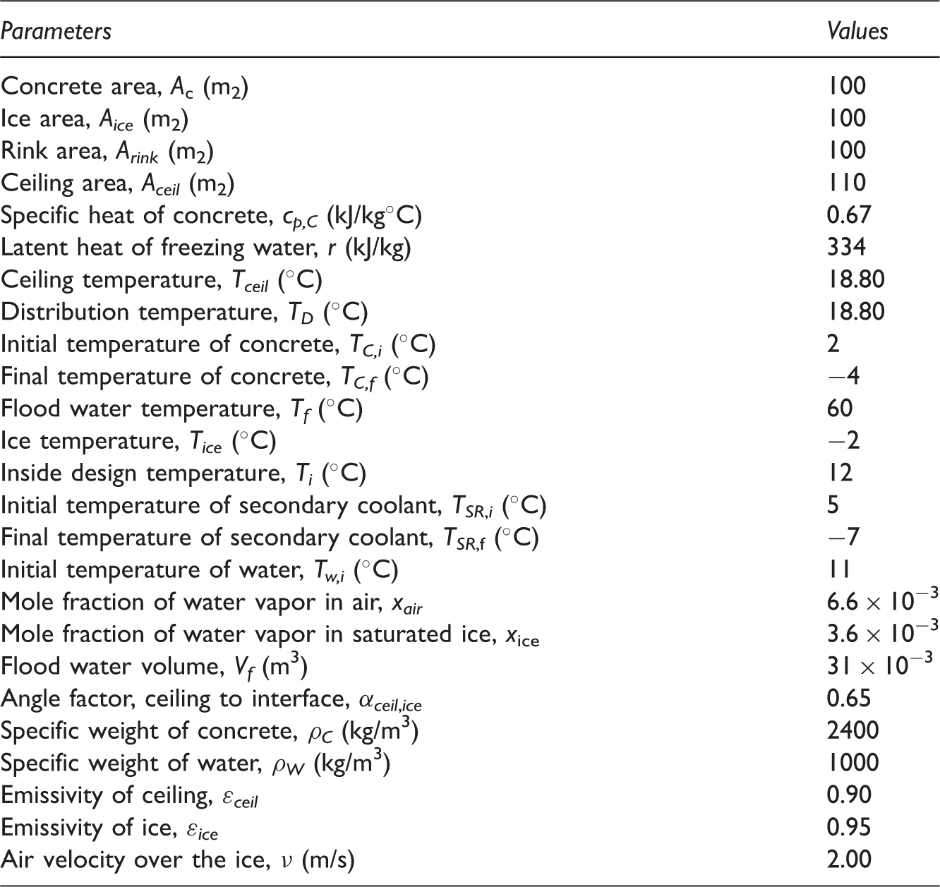
In addition, dimensionless cooling load is calculated for all months of whole year using assumed hourly average temperatures, the inside design air temperature, and the hourly outside temperatures. Net energy charged to the storage is computed from equation (23).
Results and discussion
In this study, effects of the ice rink cooling system parameters on the long-term performance parameters for the ice rink cooling system with underground TES tank are investigated. The system parameters are earth type, storage volume, and ice rink area. Performance parameters are known as water temperature, CF, COP of the chiller unit, and energy fractions. These parameters are estimated by executing the computer code developed in Matlab for an ice rink located in Gaziantep (37.1°N), Turkey. Results obtained from the numerical computations are shown in the figures and discussed in the following subsections.
Effect of earth type on storage temperature
Storage temperature is very important for a ground-coupled heat pump or chiller unit. Since, performance parameters change as functions of the storage temperature. Therefore, Figure 2 is depicted to see effects of earth types on the storage temperature. It indicates annual variation of water temperature in the TES tank during the sixth year of operation for three different geological earth types: coarse graveled earth, limestone, and granite. It is seen from the figure that the highest temperatures are at the end of summer and the lowest ones are at the end of winter. Chiller operates in all months of year, and temperature of the water in the TES tank increases as a result of energy rejected by the chiller unit. It is clear that the highest water temperatures are obtained when the TES tank is surrounded with sand, and the lowest one is obtained for the limestone. The limestone will give better performance than the sand and coarse graveled earth. Thermal conductivity and diffusivity have strong effect on the water temperature. Since, the limestone has higher thermal conductivity and diffusivity than those of the other ones. For ice rink application, soil with higher thermal conductivity and diffusivity should be selected. These observations are in agreement with those presented in Cole et al. (2012), De Swart et al. (2001), Yang et al. (2010), and Yumrutas and Unsal (2000) and Yumrutas et al. 2003, 2005) for annual periodic operation of the system under investigation.
Annual temperature variation of water in the TES tank for November (Aice = 100 m2, CE = 40%, V = 100 m3). CE: Carnot efficiency; TES: thermal energy storage.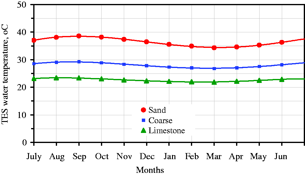
Long-term monthly variation of water temperature of the TES tank surrounded with three different types of earth for November is shown in Figure 2. It indicates that sand gives higher TES tank temperatures when compared with those of coarse or limestone. When the thermophysical properties of the three types of earths (Table 1) are compared, both of the thermal conductivity and diffusivity values for the sand are lower than corresponding values of these properties for the limestone. Also, heat capacity of the sand is lower than the corresponding values of this property for the other types of earth. Another observation depicted in Figure 2 is rapid variation of TES tank temperatures during the first few years of operation. Variations of the TES tank temperatures increase up until the sixth year of operation for all geological structures. After sixth year of operation, TES tank temperatures do not change, which indicates periodic operating conditions thereafter. After the periodic conditions, energy input to the TES tank will be equal to energy loss to the earth surrounding the tank, and all performance parameters do not change or stay constant.
Variation of storage temperature with years
Variations of storage temperature and performance parameters with respect to years are very important to determine number of year at which the water temperature reaches to annual periodic conditions. In order to see rate of the variations of the storage temperature with the years, Figure 3 is depicted for annual temperature variation of water in the TES tank for sand during the first, second, fifth, and sixth years of operation. It is seen from the figure that annually periodic operating conditions reach after the fifth year of operation. During the sixth year of operation, water temperatures do not change, and there is no effect of year on the storage temperature. After the sixth year, the cooling system starts to operate periodically. This year is called as a periodic year at which the cooling system reaches the periodic conditions. After periodic year of operation for the cooling system, performance parameters will stay constant.
Annual temperature variation of water in the TES tank with number of operation years (sand, Aice = 100 m2, CE = 40%, V = 100 m3). CE: Carnot efficiency; TES: thermal energy storage.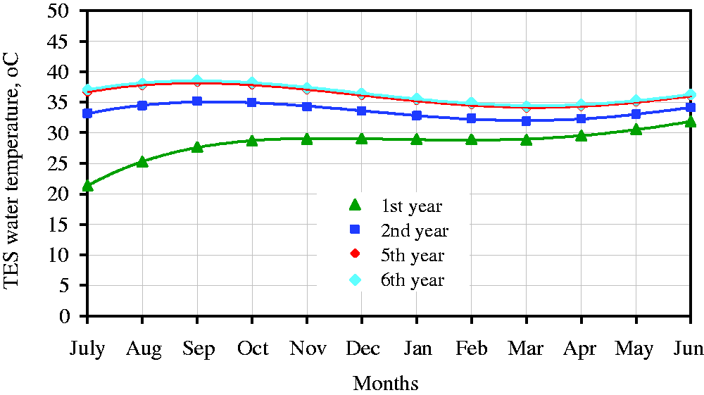
Figure 4 indicates long-term variation of water temperature of the TES tank surrounded with three different types of earth for November. As it is seen from the figure, sand yields higher TES tank temperatures when compared with coarse or limestone. When the thermophysical properties of the structures as listed in Table 1 are compared, both thermal conductivity and heat capacity values for sand are lower than corresponding values of these properties for the other types of earth. The thermal conductivity has an important effect on the storage temperature and performance parameters. Another observation from Figure 4 is rapid variation of TES tank temperatures during the first few years of operation. Increase of the TES tank temperatures continues up until the fifth year of operation for all geological structures, and TES tank temperatures do not change after fifth year of operation indicating periodic operating conditions thereafter.
Effect of earth type on annual temperature variation of water in the TES tank during sixth year of operation (Aice = 100 m2, CE = 40%, V = 100 m3). CE: Carnot efficiency; TES: thermal energy storage.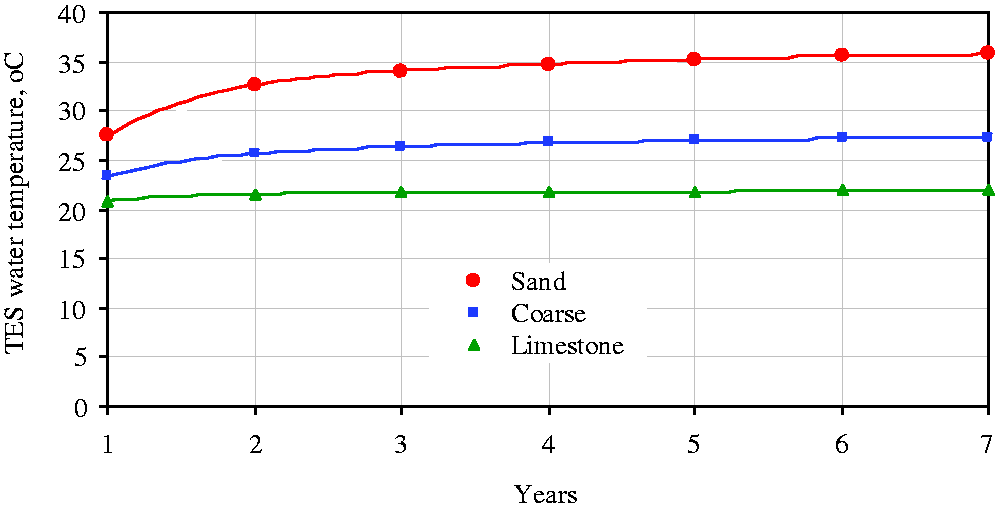
Effect of CE on tank temperature and COP
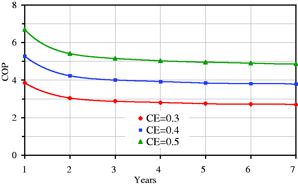
CE is defined as ratio of actual COP to theoretical COP, which is important for finding of the chiller performance. A practically reasonable CE value was used in the study. As it is known, actual COP depends on the types and size of a real chiller at different temperature lifts. It is reported in Zogou et al. (1998) that CE values in the 0.30–0.50 range for small electric heat pumps and accordingly three CE values (0.30, 0.40, and 0.50) were considered in the present study. Results obtained for monthly variation of the TES tank temperature during the sixth year of operation and long-term variation of COP are shown in Figures 5 and 6, respectively. Higher CE values yield lower TES water temperatures, and this is depicted in Figure 5. Effect of CE on the TES tank temperature is small as it is seen in Figure 5. But, its effect on the COP is high as seen in Figure 6. COP decreases with years up until annually periodic operational conditions are achieved. Annual COP value does not change once annually periodic operational conditions are achieved. Effect of the CE on the TES tank temperatures reported in this study is in agreement with results in Yumrutaş et al. (2003).
Effect of CE on annual temperature variation of water in the TES tank during sixth year of operation (sand, Aice = 100 m2, V = 100 m3). TES: thermal energy storage. Effect of CE on COP of the chiller (sand, Aice = 100 m2, V = 100 m3). COP: coefficient of performance.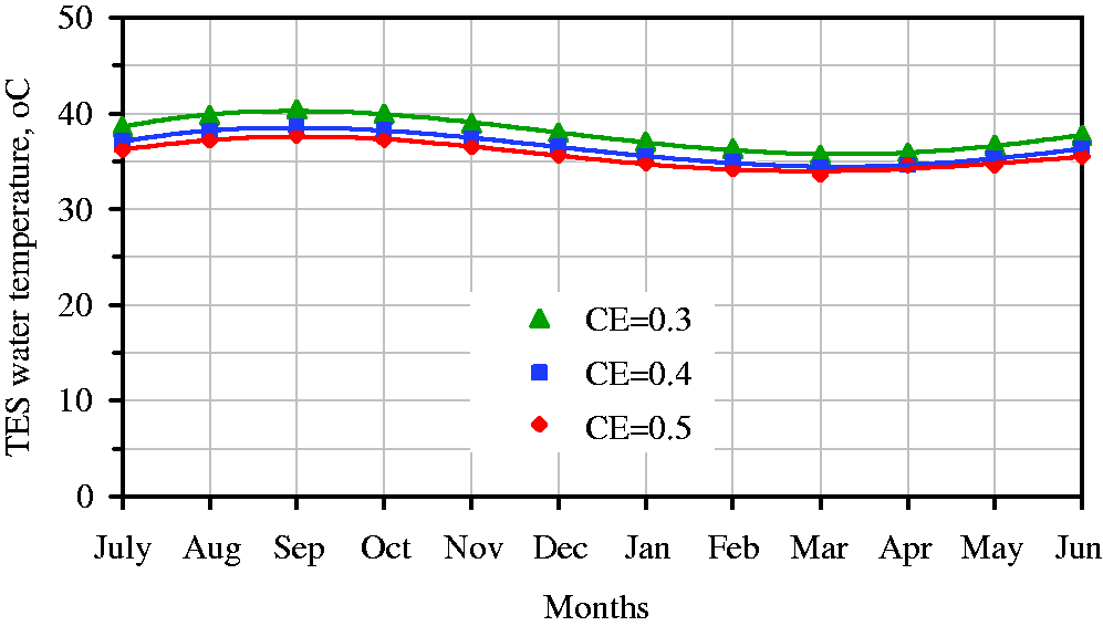
Effect of storage volume on tank temperature and COP
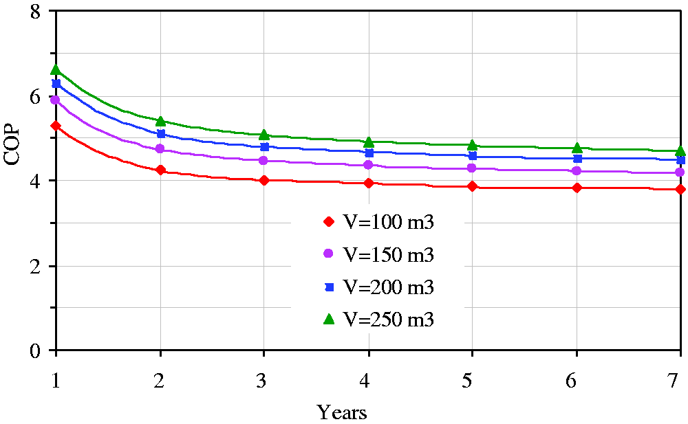
Figures 7 and 8 were prepared to emphasize effects of the TES tank size on system performance. Figure 7 shows variation of water temperature in the TES tank for four different tank volumes during the sixth year of operation. It can be seen from Figure 7 that amplitude of the water temperature increases when the tank size is decreased. Decrease in the TES tank temperature will decrease evaporation temperature of the refrigerant in the chiller cycle. This, in turn, increases the difference between evaporating and condensing temperatures resulting in an increase in chiller work and a decrease in the chiller COP (Yumrutas et al., 2005). On the other hand, as the temperature difference between the sink and the source decreases, work required by the chiller decreases (Yumrutas et al., 2005). Variation of the COP of the chiller unit with years is given in Figure 8 for four different tank volumes. COP increases with the TES tank size. It increases up to the sixth year of operation for all tank sizes. Change in COP is negligibly small after the sixth year. It is also seen in this figure that the change in COP is small when the tank volume is increased from 200 to 250 m3.
Effect of storage volume on annual storage temperature during sixth year of operation (sand, Arink = 100 m2, CE = 40%). Variation of COP with tank volume and operation time (sand, Arink = 100 m2, CE = 40%). COP: coefficient of performance.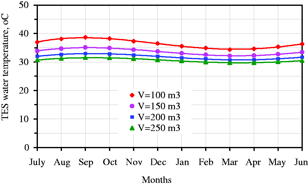
Effects of ice rink are on tank temperature and COP
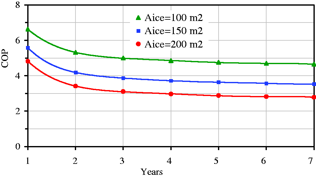
Effects of an ice rink area on the TES tank temperature and on the COP of the chiller are depicted in Figures 9 and 10, respectively. Both figures are depicted for sand and storage volume of 200 m3. It is seen in both figures that the TES tank temperature increases, and COP decreases with increasing ice rink area. As shown in Figure 9, when area of ice rink is taken 100 and 150 m2, annual variation of the storage temperature and COP of the chiller unit can be accepted reasonable ranges. However, ice rink area above 150 m2 requires bigger storage volume. Since, the COP value decreases below 3 after fourth year of operation or long-term operation. And then, it is observed in Figure 10 that the cooling system reaches an annually periodic operating condition within six or seven years for the system parameters considered in this study.
Effect of an ice rink area on annual storage temperature during sixth year of operation (sand, CE = 40%, V = 200 m3). Effect of an ice rink area on COP of chiller (sand, CE = 40%, V = 200 m3). COP: coefficient of performance.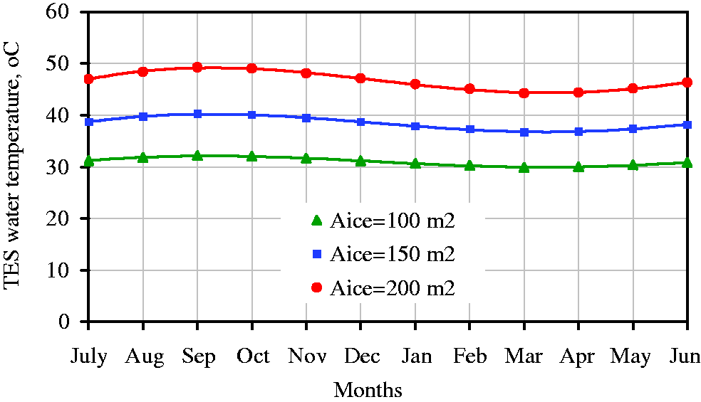
Variation energy fractions
Energy balance of the ice rink cooling system is important. Therefore, it is necessary to define energy input and energy output for the system. Total yearly energy input to the energy storage tank during all time in year consists of heat gain by the ice rink and energy consumption by compressor of chiller unit. The energy input to the tank is partially stored in the tank, partially lost into the surrounding earth. In the present study, energy fractions are defined as the ratio of each energy component to the total yearly energy supplied to the storage tank. Annual energy balance of the system during the first, second, third, and sixth years of operation is shown in Figure 11. It indicates that heat gain of the ice rink decreases and compressor work increases with years. Beside this one, energy stored in the tank decreases, and energy lost to the ground increases with years. The TES tank temperature that stays constant for periodic operation implies that no energy is stored in the TEs tank after sixth year of operation. Consequently, performance of the chiller (COP) increases with years due to decreasing heat gain of the ice rink.
Variation of energy fractions with years of operation (sand, Arink = 100 m2).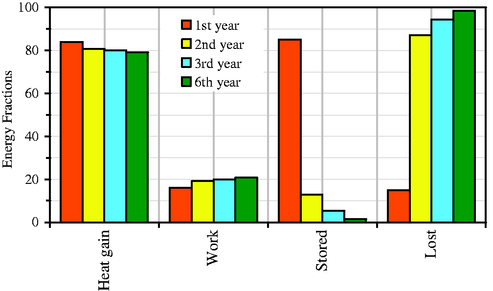
Conclusions
A hybrid analytical and computational model for finding long-term performance of an ice rink cooling system with an underground TES tank is presented in this study. A computer code based on the mathematical model is developed, which is used to investigate the effects of number of operation years, thermophysical properties of earth surrounding the TES tank, CE of the Chiller, storage volume, and ice rink area on the TES tank temperature and on thermal performance of the system considered. As depending on system parameters, results indicate that an operational time span of 5–7 years will be sufficient for the cooling system to reach an annually periodic operating condition. Thermophysical properties of earth around the tank affects the performance of the system and sand earth yields the best thermal performance from within the three earth types considered in this study. Thermal conductivity has strong effect on the system performance. CE has a small effect on the TES tank temperature while having a stronger effect on the COP of the chiller.
Highlights
An analytical model of an ice rink cooling system with an underground energy store was developed. The model was based on energy analysis of the ice rink, energy need of a chiller unit, and solution of transient heat transfer problem for the store. The solution of the store problem was obtained using a similarity transformation and Duhamel superposition techniques. An interactive computer program in Matlab based on the analytical model was prepared to find performance parameters.
Footnotes
Declaration of conflicting interests
The author(s) declared no potential conflicts of interest with respect to the research, authorship, and/or publication of this article.
Funding
The author(s) received no financial support for the research, authorship, and/or publication of this article.