
Abstract
Gas drainage has been the most common technique for gas management in underground coal mines. This method involves drilling holes into a virgin coal seam to allow the gas bleed off from the coal into the drainage holes. A major problem with the underground gas drainage is the air leakage around the gas drainage hole that cannot be blocked off by the sealing material. The air leakage will cause the low concentration of the drained gas and decrease the efficiency of the gas drainage hole, which may further lead to many other risks, such as spontaneous combustion, gas combustion and gas explosions. A thin spray-on liner is defined as a chemical-based layer or coating (3–5 mm) that is sprayed onto the rock surface to support mining excavations. Since their introduction, thin spray-on liners have received some success as a ground support tool for underground mining. Besides ground support, thin spray-on liners also show some potential to be used as a gas management tool in underground coal mines due to their relatively low permeability. This paper describes a field trial of using thin spray-on liners for enhancing the gas drainage efficiency by blocking the fractures around the drainage holes. The project involves spraying a thin spray-on liner onto the area surrounding gas drainage holes whereby the thin spray-on liner acts as a thin membrane decreasing the permeability of coal. This restricts the air migrating through the coal seam and diluting the gas from the drainage holes. The key benefits associated with the application of TSLs are the increase in the methane purity and the decrease in the air contamination. In-situ adhesion tests were conducted in parallel with the gas tests, and the results revealed that the TSL tested could be implemented for underground coal mine applications as the main failure mode is the internal failure of the coal substrate.
Introduction
Coal seams contain gases in quantities which are functions of coalification degree and permeability of the overburdens (Noack, 1998). Gas and coal are formed together during coalification, a process in which biomass is converted by biological and geological processes into coal (Warmuzinski, 2008). Coal seam gas composition is typically greater than 90% methane, with minor amounts of liquid hydrocarbons, carbon dioxide, and/or nitrogen (Jenkins and Boyer, 2008). During mining, gas is constantly released from coal seams and the surrounding strata, and is emitted into the ventilation system. Inadequate air quantities in the ventilation system may cause dangerous gas accumulations in the mine and may lead to gas explosions under certain conditions (Lunarzewski, 1998). When disturbed by the mining excavations, the gas stored in the coal seam may cause coal and gas outburst events and pose a significant threat to the mine safety (Lama and Saghafi, 2002). The emission of gas may also result in an environmental problem, as methane, the main component of coal seam gas, is a greenhouse gas (GHG) with the global warming potential (GWP) around 21 times that of carbon dioxide (Warmuzinski, 2008). However, methane is clean and a high efficient energy source (Flores, 1998; Karacan et al., 2011). To improve mine safety, reduce the GHG emission and recover the methane as a resource, every coal mine has to take a series of measures for the coal seam degasification and recovery.
Gas drainage using pre-drainage and/or post-drainage has become a useful technique for gas management in underground coal mines (Brunner et al., 1997). Pre-drainage methods aim to reduce the gas content of coal bed before mining for the purpose of decreasing gas emissions during development and longwall production. Post-drainage methods aim to capture gas during longwall phases to reduce the gas amount managed by ventilation. Besides reducing the gas content of the coal bed, gas drainage is also effective for decreasing the risk of coal and gas outburst by reducing the pressure of the coal seam near the mine workings (Liu et al., 2014; Noack, 1998). However, a serious air leakage may develop around a drainage borehole due to the coal excavation process (Xia et al., 2014a), and result in a decreased gas concentration, as shown in Figure 1. This low-concentration gas may also cause many other risks, such as spontaneous combustion, gas combustion and gas explosion (Xia et al., 2014b). The material that seals the space between the drainage pipe and the borehole can only seal the borehole; however, the internal cracks in the coal seams cannot be blocked off by the sealing material (Lu et al., 2014).
Schematic of air leakage around a gas drainage borehole (modified from Xia et al., 2014a).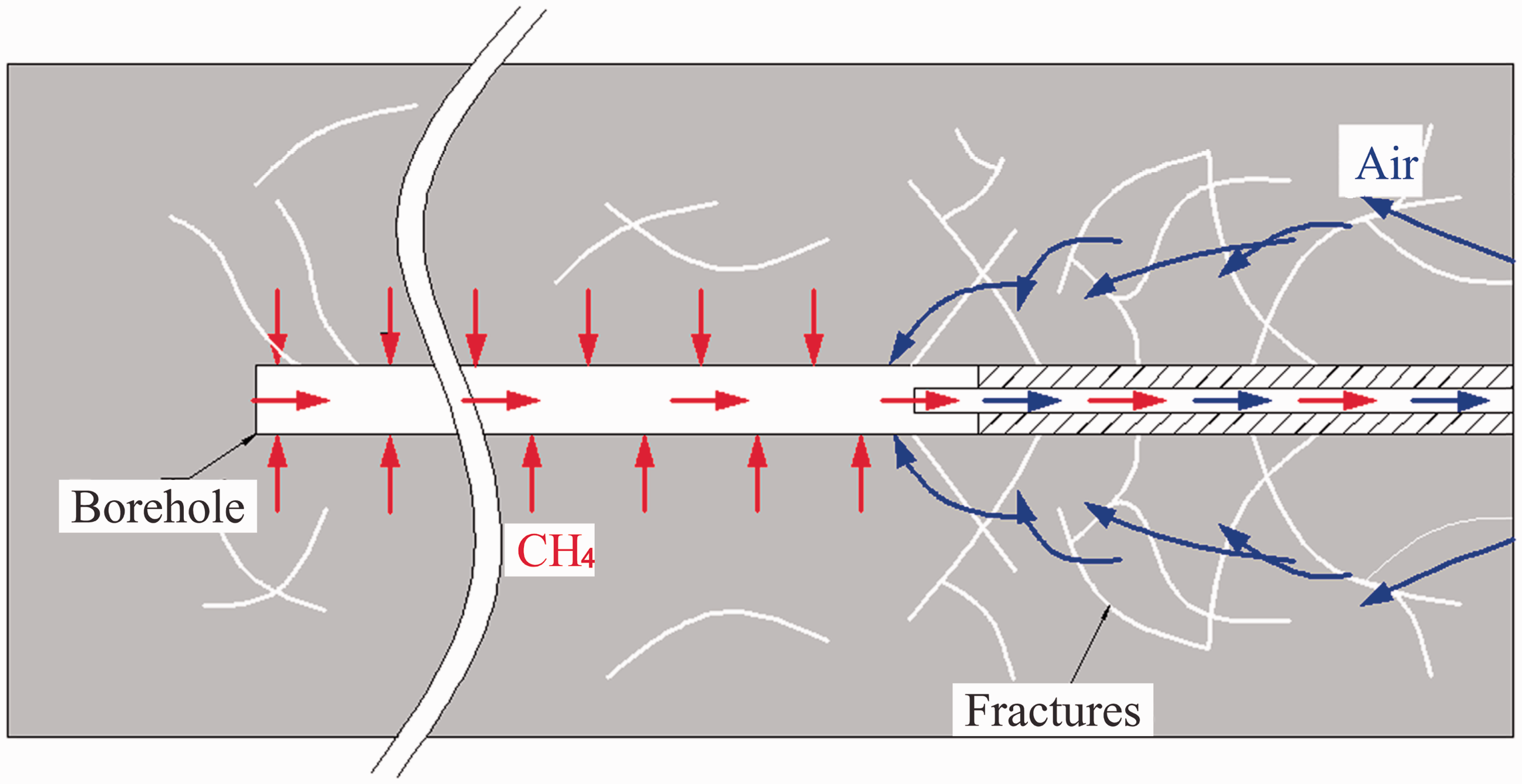
A thin spray-on liner (TSL) is defined as a thin chemical-based coating or layer that is applied onto the mining excavations with a thickness of 3–5 mm (Lau et al., 2008; Richardson et al., 2009; Saydam and Docrat, 2007). They are generally a combination of liquid–liquid or liquid–powder components that are sprayed onto the rock surface, where strong bond with the rock develops (Gilbert et al., 2010). TSLs have been used in civil engineering as sealants for many years before being introduced to mining industry (Kuijpers, 2004; Yilmaz et al., 2003). TSL materials for mining industry were initially designed as rock sealants to limit the weathering of rock and later were intended to be used as a substitute to mesh or shotcrete (Spearing et al., 2009; Yilmaz, 2007). The idea of using TSLs as a surface support was initiated in the late 1980s in Canada and was originated with the idea that a liner as thin as 5 mm should perform the same as or even better than shotcrete (Archibald, 2004; Yilmaz, 2011). Since the 1990s, TSL support has become popular in the mining industry due to the considerable operational benefits, with the potential to reduce costs (Ozturk, 2012).
TSLs have been under research and development for over 20 years, with numerous trials conducted in underground mines. Potvin et al. (2004) listed the most common usages of TSLs, and these applications were usually at locations with exceptionally adverse ground conditions or ground control problems.
Support between rock anchors Supporting areas with limited access and/or logistics constraints Mesh replacement As primary support immediately after blasting Temporary support (before shotcrete) Temporary support in TBM tunnels (poor ground conditions) Reduce rockburst damage Pillar reinforcement Face support Large machine borehole lining and stabilisation Stabilisation of return air tunnel Ore pass lining Prevention of rock falls Rigid ventilation seals Ground degradation (weathering fretting, swelling and slaking) Ground alteration (moisture, heat, humidity and chemical contamination)
Advantages of TSLs are fast application rates, rapid curing time, reduced material handling compared to shotcrete, high tensile strength with high areal coverage, high adhesion which enables early reaction against ground movement, and ability to penetrate into joints (Kuijpers et al., 2004; Pappas et al., 2004). These properties will ease logistics, improve on cycle time, increase mechanization, and improve safety for underground support (Stacey, 2001). Despite these benefits, the original aim of using TSLs as an alternative to mesh and shotcrete has not yet been achieved. Most of the products on the market are still under development and no reports yet exist about TSLs being systematically applied as surface support in mines (Darling, 2011). However, it should be noted that a TSL application may not replace a traditional ground support such as rock bolts. It can only be considered as a temporary or combined support with other ground support tools. Nevertheless, TSLs have performed well when combined with other types of support, such as rock bolts + TSL + shotcrete and rock bolts + TSL + mesh + shotcrete (Hussain et al., 2012).
Besides ground support, TSLs also show potential to be used as a gas management tool in underground coal mines due to their relatively low permeability. Archibald and De Souza (1993) measured the radon gas blocking capacity and gas permeability of different TSL materials and thicknesses. They emphasised the potential use of TSLs in restricting hazardous gas inflows.
Maas and Renken (1997) assessed the effectiveness of different cementitious coatings as barriers to radon gas entry. Their results showed that the coatings tested all exhibited excellent permeability as they were two to three orders of magnitude smaller than the average concrete permeability. Further results indicated that any sealant placed on a highly permeable concrete would significantly reduce the permeability. It is important to note that the hazardous gases, easily diffusing from rock pores into the working area, cannot be effectively blocked by shotcrete (Tannant, 2001).
Saghafi and Roberts (2001) reported measurements of the permeability of a TSL product for methane, carbon dioxide and carbon monoxide. Their results indicated that the permeability of TSLs was in the range of nano darcies. They also pointed out that the permeability for methane and carbon dioxide were very similar while the permeability for carbon monoxide was a few times higher. Hussain et al. (2012) conducted permeability tests on coal samples coated with three different TSLs for carbon dioxide and nitrogen. This was the first test that had investigated the interaction between TSLs and coal. The experimental results showed that the TSLs tested can reduce gas permeability of coal by up to three orders of magnitude.
Laboratory tests of thin spray-on liners
Permeability characteristics of TSLs
Before the in-situ trial, laboratory gas flow tests were conducted on coal samples coated with TSL to investigate the permeability characteristics of the tested TSL. The permeability of a coal sample is measured by injecting dry gas through the sample and measuring the flow rate and differential pressure across the sample. A “Hassler” type core holder was used for the tests. A schematic view of the test apparatus is shown in Figure 2. The tested gas phases included methane and carbon dioxide, as they the main gases of concern for underground coal mining, and helium was used as a control gas to investigate the effect of gas sorption on the permeability results. The test results revealed that the application of the chosen TSL can reduce the permeability of coal by at least two to three orders of magnitude (Li et al., 2015a).
Schematic view of the permeability test apparatus (Li et al., 2015a).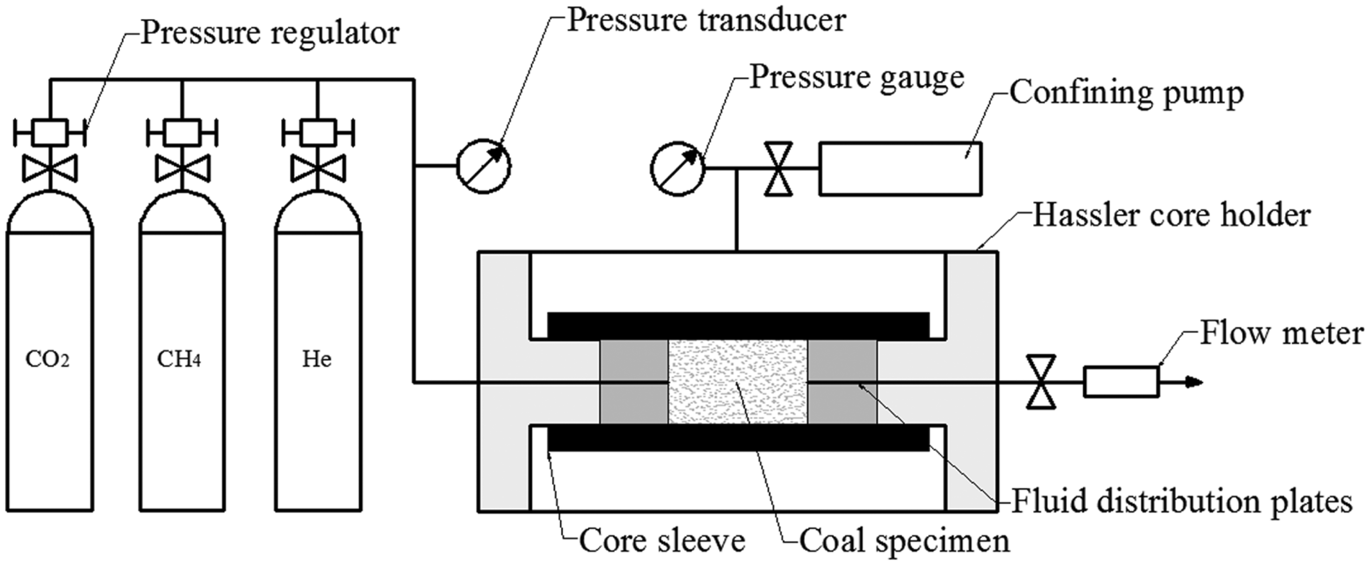
Tensile properties of TSLs
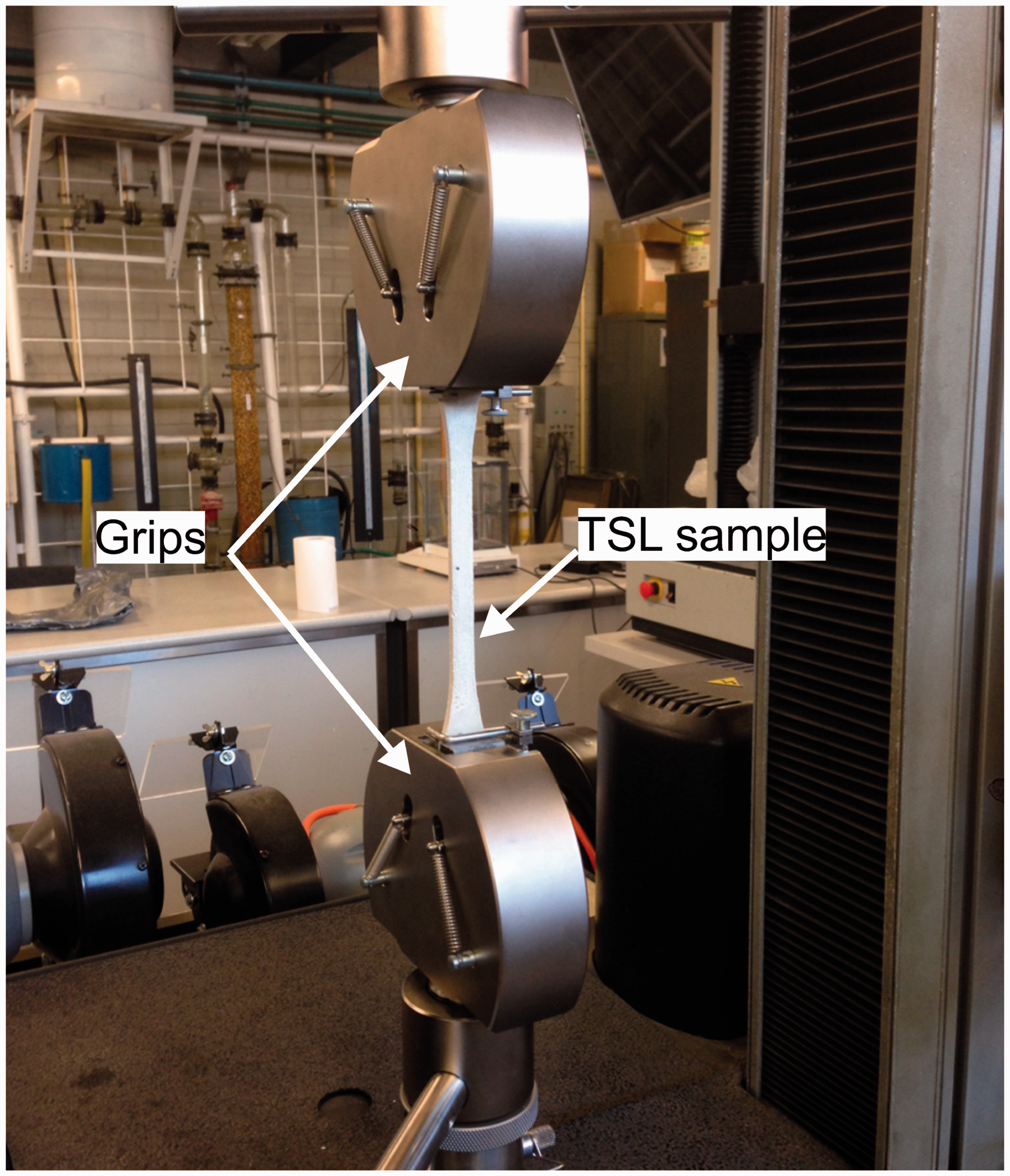
Tensile strength testing has been one of the most common physical property testing methods of TSL products (Yilmaz, 2010). Laboratory tensile strength tests were carried out to determine the tensile strength, deformation modulus in tension, and elongation capacity of the tested TSL. The Standard Test Method for Tensile Properties of Plastics (ASTM D638) was selected and used in this test, as it has been regarded as a primary liner characterisation test by many researchers (Archibald, 2001; Baafi et al., 2011; Kuijpers et al., 2004; Spearing and Gelson, 2002; Tannant et al., 1999; Toper et al., 2003; Yilmaz, 2010). A “dogbone”-shaped specimen was used in this test with a thickness of 5 mm, and the dimensions are shown in Figure 3. The test apparatus is a universal tensile testing machine with a maximum capacity of 5 kN. The test apparatus is shown in Figure 4.
Shape and dimensions of the tensile strength test specimen (ASTM D638, 2010). Tensile strength test set up.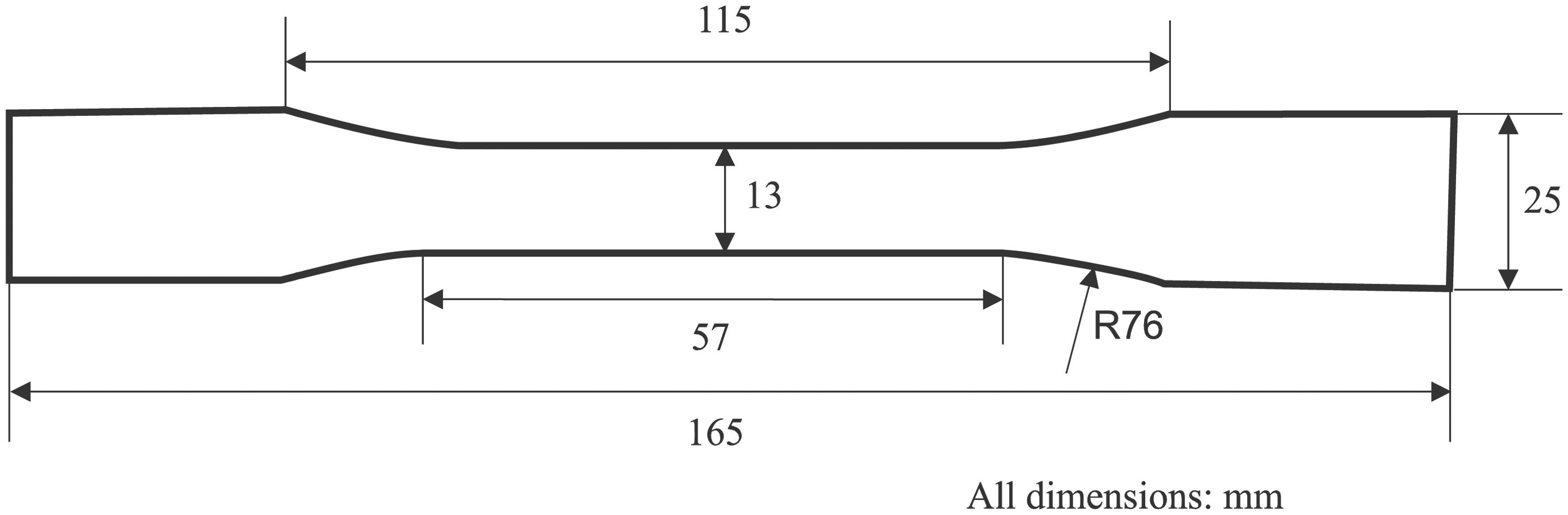
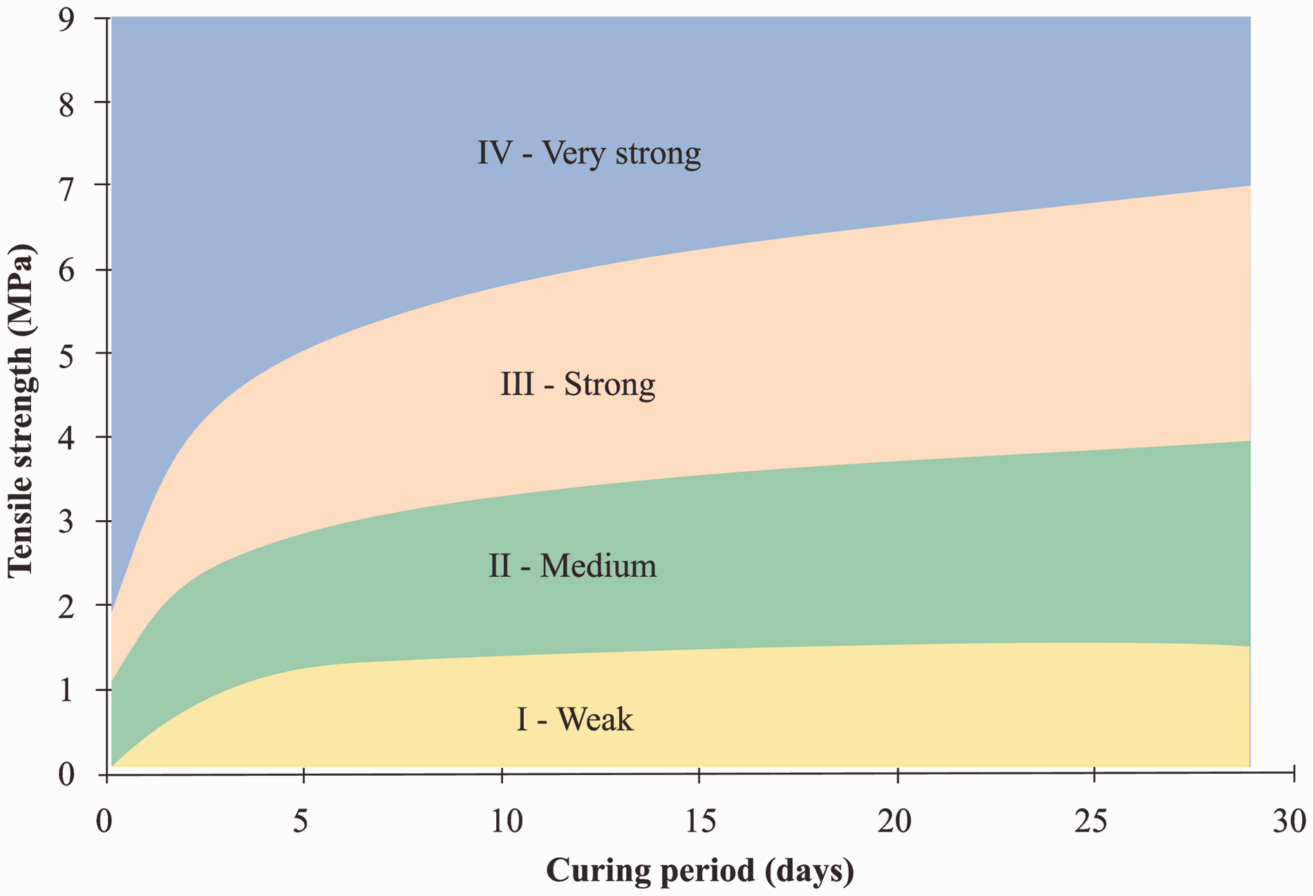
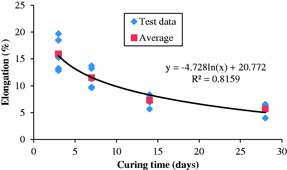
Tensile strength tests were conducted on samples with different curing time: 3 days, 7 days, 14 days and 28 days. Five samples were prepared for each curing conditions. The results show that the tensile strength increases with the curing time, as seen in Figure 5. After three days curing, the tested TSL had a tensile strength of about 1.6 MPa. The final tensile strength reached 3.5 MPa. Based on the criteria proposed by Yilmaz (2010), the tested TSL is in the strong category, as shown in Figure 6. From the elongation results shown in Figure 7, it can be observed that as the curing time increases, the elongation capacity of the tested TSL tends to decrease.
Tensile strength with different curing time. Tensile strength categories of TSLs (Yilmaz, 2010). Elongation with different curing time.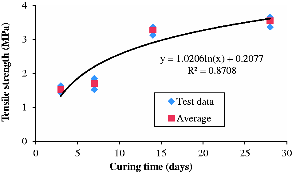
In-situ tests
Gas management in the mine
The trial was conducted at an underground coal mine in the Southern Coalfields, about 25 km northwest of Wollongong in the Macarthur region of New South Wales, Australia. The coal is extracted from the Bulli Seam at a depth of up to 560 m, with seam thickness between 2.1 m to 3.4 m. The produced coal is premium, hard quality coking coal used for steel production by companies from Australia and around the world.
The mine produces around 6.5 million tonnes of coal per annum from longwall retreating faces with a width of about 300 m. Two heading gate roads are driven on both the maingate and tailgate side of the longwall panel. Methane and carbon dioxide are the most common gases present in the mine, with the gas content of the coal seam ranging from 2 to 16 m3/t.
Due to the high seam gas content and adjacent coal seams, gas emissions around the longwall made managing gas levels, particularly methane, in the ventilation circuit and face area a difficult task. As a response to the gas emission problem, a methane drainage system was introduced to the mine, including a surface suction plant and pipe reticulation of the gas to the surface (Eade, 2002).
The mine utilises hydraulic directional drill rigs for the inseam drilling. Directional drilling technology provides a methodology that allows for a hole in a coal seam to be drilled in a pre-determined direction. Compared to the traditional drilling method, the directional drilling technology has many advantages including high proportion of in-seam boreholes, high borehole drill suitability, enhanced gas drainage efficiency, and low gas control cost (Wang et al., 2012). The holes are drilled in a fan pattern from the stubs into the future longwall blocks. The spaces between the boreholes vary depending on the permeability and the structures in the drilling area. These boreholes can serve two purposes: reducing the methane content of the coal seam prior to mining and shielding the developing entries from gas migration (Diamond, 1994).
Trial location
The location of the trial site was on the tailgate of a longwall panel between the two adjacent cut-throughs. Figure 8 shows the approximate locations of the gas drainage holes in relation to the gas drainage stub and other nearby longwall panels. It should be noted that the borehole locations are just approximate and not to scale. Before the trial application, 10 fan pattern boreholes were drilled into the solid, virgin coal to reduce the gas content of longwall panel 1 as well as shield the development headings of the maingate.
Location plan of the test site (not to scale).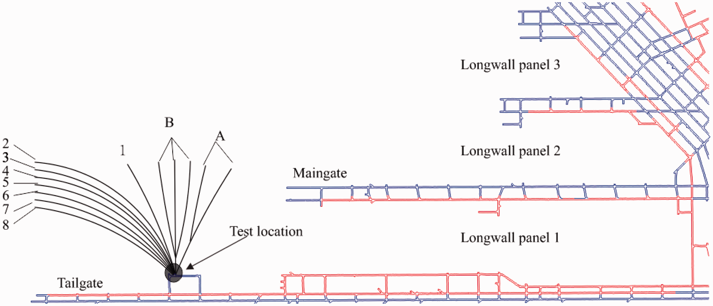
For this project, TSL material was sprayed onto the rib and roof areas surrounding the gas drainage holes, as shown in Figure 9. The main aim of this field trial was to investigate the effect of TSL application on methane purity and flow rate of the gas drainage holes. The methane purity was expected to increase after the application of TSL, as TSL application can increase the air pathway resistance from excavations into drainage holes and then reduce the ventilation air migration, which is the leading cause of gas dilution.
Intended TSL application areas on the rib and the roof (Not to scale) (modified from Tenney et al., 2015).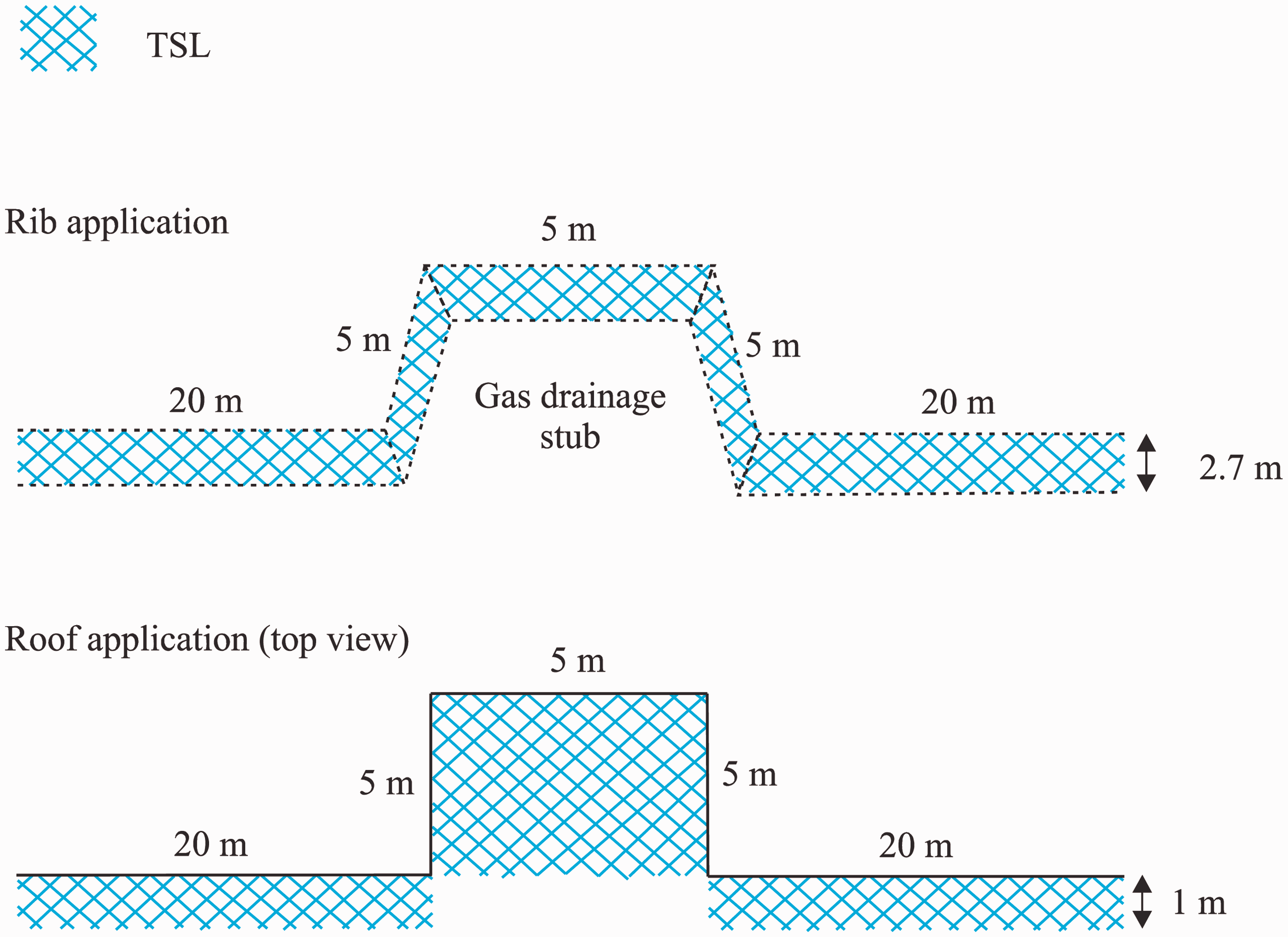
TSL application
The sprayed TSL is a one-component polymer powder available in 20 kg bags. Due to confidentiality agreements, the product name is not disclosed. The product is mixed with water in the spaying nozzle and impacts the substrate as a paste. The recommended ratio for the mix is about 45% water and 55% powder. The product sets within 5–10 min and progressively increases in tensile strength and bond strength over the next hours, days and weeks. The TSL material and spraying equipment are shown in Figure 10.
TSL material and spraying equipment.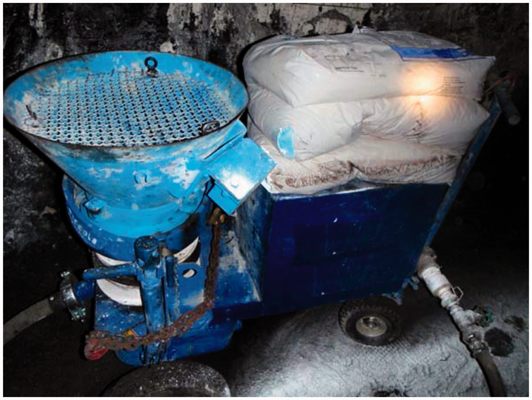
Before TSL application, debris was removed from the rib areas. It is required that the rib areas should be as accessible and clean of rubbish as possible. The ribs in the trial location were covered by stone dust prior to TSL application to prevent the explosion risk. To achieve better bond strength between the TSL and coal, water was used to remove the stone dust in the TSL application area. Based on previous research, dust can significantly decrease the adhesion strength of TSL materials (Ozturk and Tannant, 2011). After preparation, TSL material was sprayed onto the rib areas surrounding the gas drainage holes with a thickness of about 5 mm, as shown in Figure 11.
TSL application onto the rib surrounding the gas drainage holes.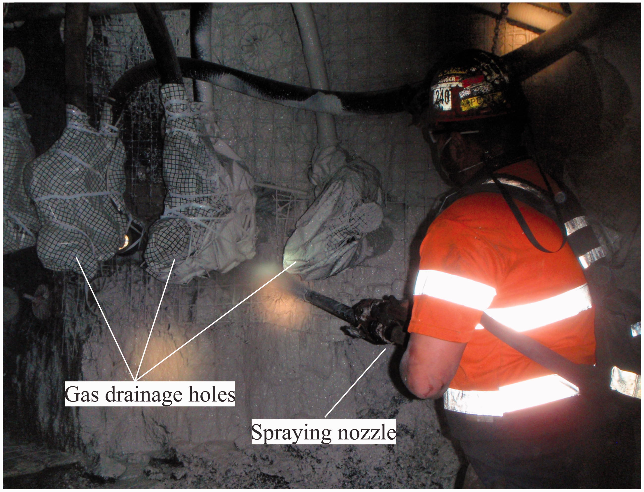
Data collection
Gas composition
The gas sample from each drainage pipe was collected with the help of a water-driven pump, as shown in Figure 12(a). After filling the gas sample bags, they were carefully sealed and labelled, as shown in Figure 12(b). Later, all the gas samples were taken to the gas laboratory located at the mine site for the gas composition analysis.
(a) Gas pump with an air hose attached (b) gas sample bag.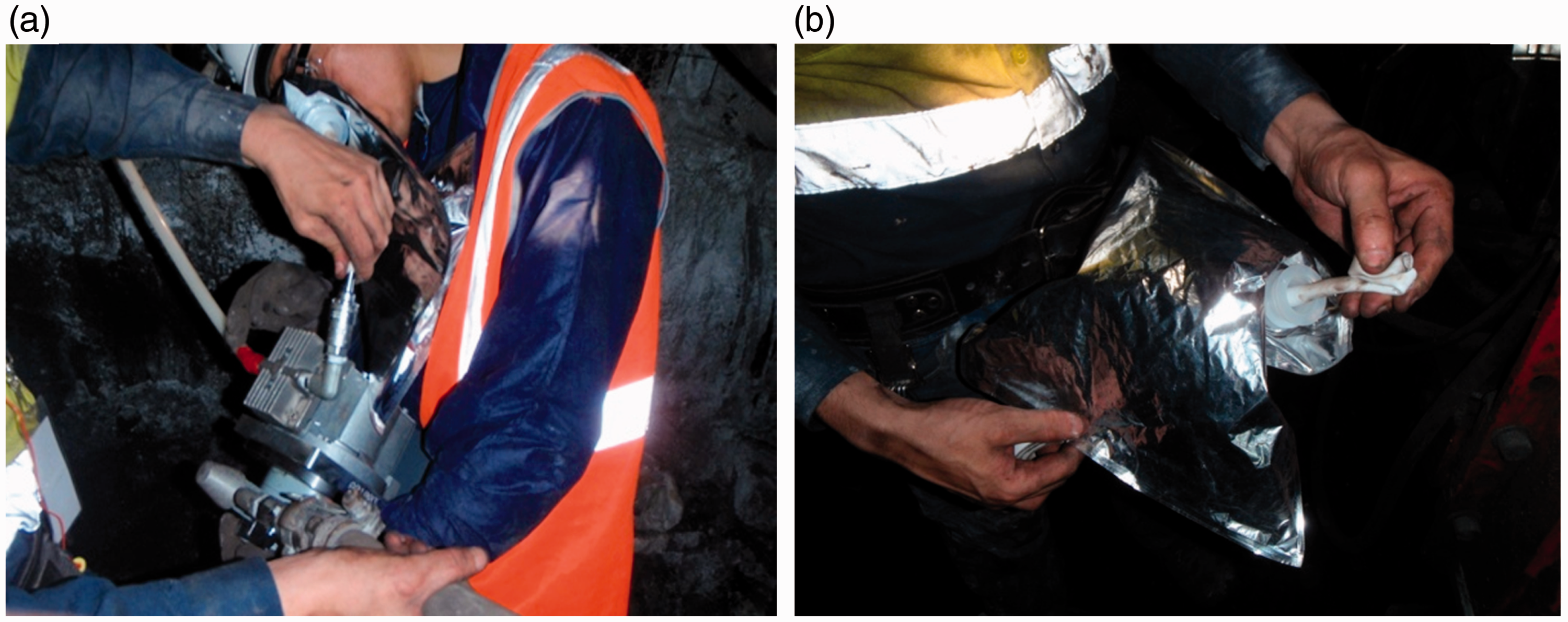
Measuring flow rate and suction pressure
The flow rate in each drainage hole was calculated by measuring the differential pressure over the orifice plate, as shown in Figure 13(a). The suction pressure was also measured for each drainage hole, as shown in Figure 13(b).
(a) Taking differential pressure over the orifice plate; (b) measuring suction pressure.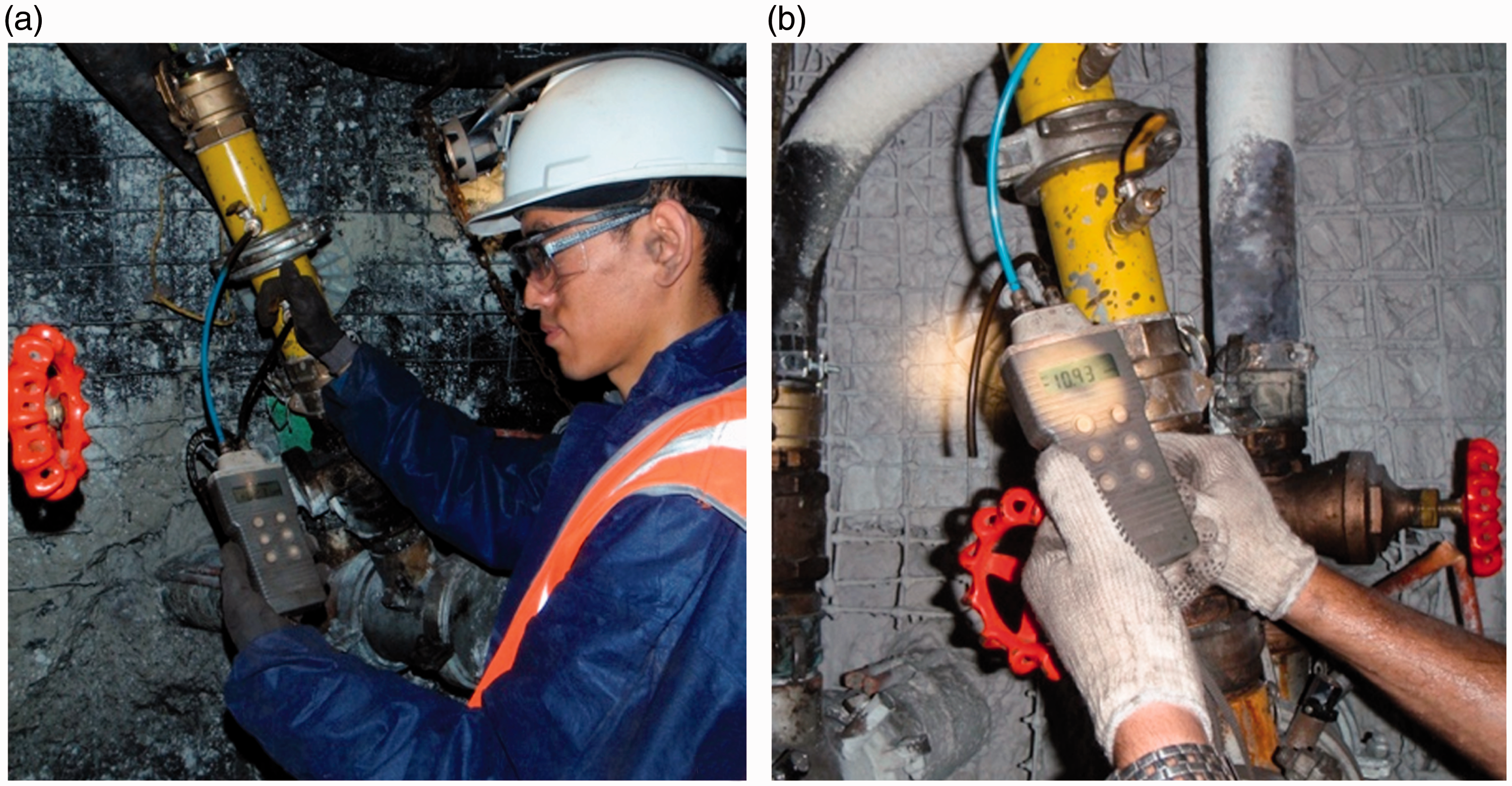
Gas test results and analysis
Methane purity
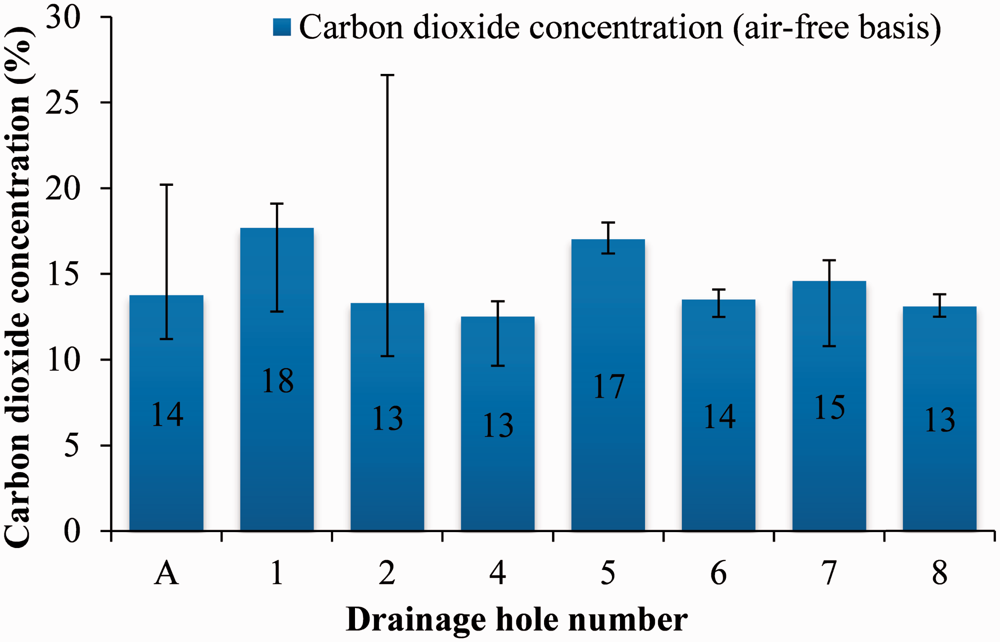
Coal seam gas is made up of mostly methane and carbon dioxide. The average methane and carbon dioxide concentration results for each drainage hole are shown in Figures 14 and 15. The gas concentration results are analysed on an air-free basis. The coal seam gas composition for the test area is about 86% of methane and 14% of carbon dioxide.
Average methane concentration for each drainage hole. Average carbon dioxide concentration for each drainage hole.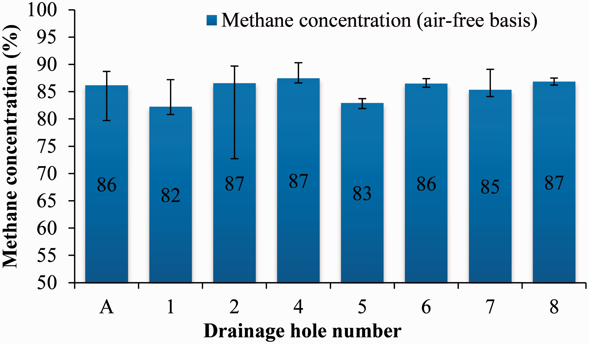
Methane purity from the drainage holes can be influenced by two factors: dilution by the ventilation air ingress and variability of the coal seam gas composition. The gas samples collected from the gas drainage holes were sent to the laboratory located on the mine site for gas composition analysis. The gas sample results include the concentration of methane, carbon dioxide, oxygen, nitrogen and other gases. The gas sample data were collected for each drainage holes from 12 days before the TSL application to four weeks after the TSL application. Due to some operational problems and damage to the drainage pipe, the gas results for holes B and 3 were not measured.
The methane concentrations for each drainage holes are shown in Figure 16. After the application of TSL, there was a dramatic increase in methane concentrations for holes 1 and 6. The methane purity for hole 6 was only about 20% before the spraying, and after the application, the value increased to about 80%. Not much change in methane purity can be found for holes other than holes 1 and 6, as the methane concentrations for these holes were almost over than 80% before the TSL application and there was not much leakage for these holes.
Methane concentration from the gas drainage holes.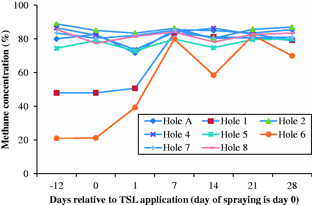
Air contamination
The coal seam gas is mainly composed of methane and carbon dioxide. If nitrogen and oxygen are found in the gas sample bags, it means that drained gas has been diluted by the ventilation air. This is called “air contamination”.
Air contamination is recorded for each gas sample collected and this can happen in a number of ways. The most likely reason is due to the negative pressure applied on the gas drainage holes. For gas drainage practice, negative pressure is usually applied on the gas drainage holes for two purposes: on the one hand, the negative pressure can prevent the gas leakage during the gas transportation, and on the other hand, it can also help desorption of gas from the coal seam. Due to this negative pressure, the ventilation air may migrate through the coal seam and dilute the drained gas. Cleats may also assist this process by providing pathways with less resistance for air to migrate.
The experimental error may also influence the air contamination results. The gas samples were collected with a water-driven pump. The air samples may be diluted if the connections are not sealed properly during the sampling. For example, one gas sample during the field test reported 100% air. This was considered as an experimental error and was removed from the test results. The air contamination results for each drainage holes are shown in Figure 17.
Air contamination results from field-test trial.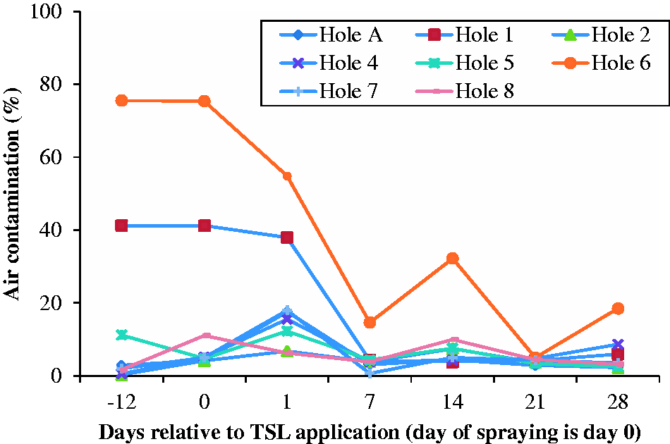
Before the application of TSL, there were significant air contaminations for holes 1 and 6, which were about 40% and 75%, respectively. This means serious air leakage existed for these two drainage holes. For comparison, the air contaminations for other holes were all lower than 20%, with relatively small amounts of deviation. After the spraying of TSL, a dramatic decrease of air contaminants was found for holes 1 and 6, with the final value lower than 20%. However, there was not much change for the other drainage holes with a relatively low air contamination previously.
It is clear that the application of TSL has had a positive effect on holes 1 and 6. The dramatic increase in methane concentration and reduced air contamination indicate that TSL has reduced air migration from primary pathways that allow air to dilute gas drainage holes 1 and 6. These primary pathways were likely to be the fractures around the drainage holes, shown in Figure 18(a), rather than the cleats intercepting these gas drainage holes, shown in Figure 18(b). If the sealed pathways were cleats intercepting with holes 1 and 6, these cleats must have intercepted with other drainage holes, as the holes were drilled in fan patterns. However, the air contaminations for other drainage holes were not influenced. It is therefore suggested that if the cleats intercepting with the drainage holes can be identified before the TSL application, TSL can be specially applied in these cleats to have better sealing effects.
Schematic view of using TSL to seal (a) fractures around the gas drainage holes and (b) cleats intersecting the drainage holes.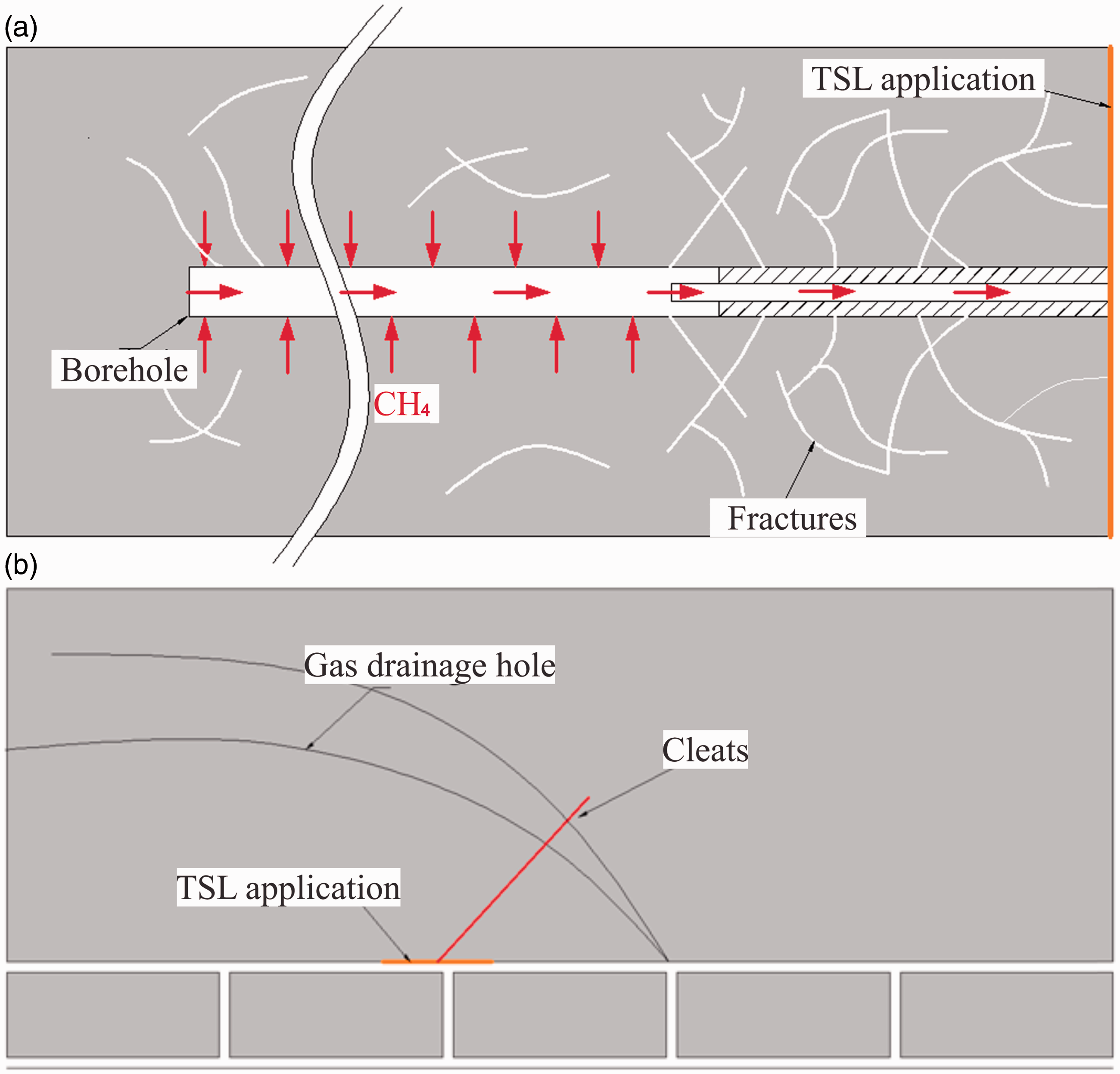
Methane flow rate
Methane flow rates for different drainage holes were calculated from the pressure differential results measured with the orifice plate. The methane flow rate results during the trial period are shown in Figure 19. As seen in the figure, the results show significant variability and no considerable conclusions can be made from the methane flow rate results.
Methane flow rate of each drainage holes throughout the study.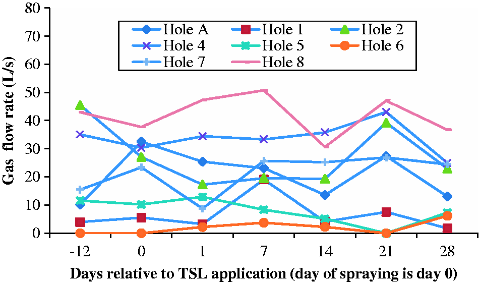
Several factors may attribute to this variation in methane flow rate results. First, the flow rate results were measured with the orifice plate and momentum flow rates were used to represent the average flow rates. Second, the water within the standpipes can influence the flow rate. Water in the standpipes can develop a wave-like motion that will cause the gas flow rate to vary due to waves pushing the gas in successions.
In-situ adhesion tests of thin spray-on liner and coal
In parallel with the gas tests, in-situ adhesion tests were also conducted to investigate the adhesion strength between the TSL and the coal substrate. The adhesion strength of a TSL can be defined as its ability to adhere to a particular surface (Swan and Henderson, 2001). Over the years, many adhesion test procedures have been proposed by researchers to assess the performance of TSLs. These adhesion test procedures can be divided into core adhesion test, embedded dolly test and glued dolly test. Glued dolly test method is the most widely used procedure by researchers due to its ease of application and accuracy of results (Archibald, 2001; Espley-Boudreau, 1999; Li et al., 2014, 2015a; Kuijpers et al., 2004; Mercer, 1992; Saydam and Docrat, 2007; Tannant et al., 1999), and was used in this study.
Description of the adhesion test
An area was specifically sprayed for conducting the adhesion tests, as shown in Figure 20. Due to the influence of the excavation, the coal in the top part is more fractured while the coal in the bottom part is relatively intact. Adhesion tests were conducted in both these regions to investigate the influence of substrate integrity on the adhesion strength. More detailed test plan and execution can be found in the paper of Li et al. (2015b).
Location of the adhesion test area.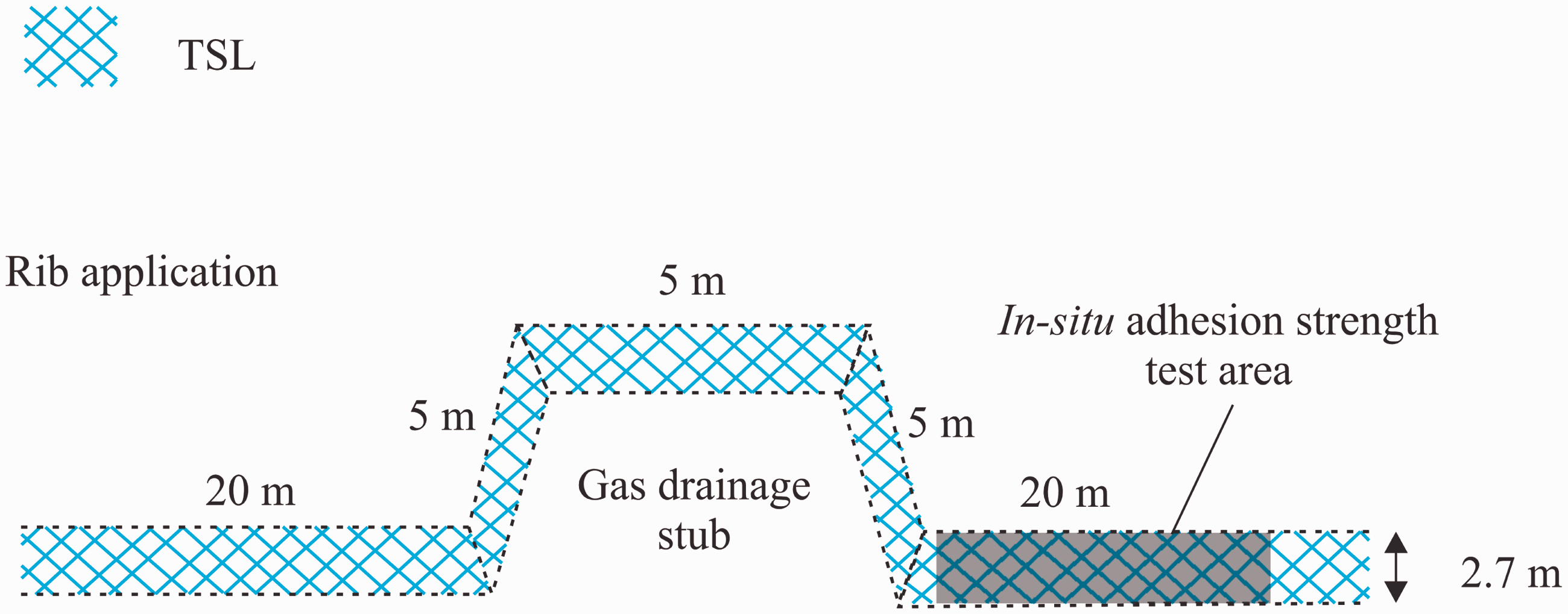
Test results and analysis
The in-situ adhesion strength test results with different curing time are shown in Figure 21. As the curing time increases, the adhesion strength firstly increases and then stabilised for both intact and fractured coal. For each curing time, the adhesion strength on intact coal is higher than that on fractured coal. For intact coal area, the adhesion strength peaks at 0.9 MPa after 14 days of curing, while for fractured coal area, the adhesion strength stabilised at about 0.55 MPa after seven days. As seen from Figure 21, the adhesion strength on fractured coal varies considerably compared to those on intact coal. Li et al. (2015b) pointed out that this may be due to the variability of the friability of the coal at each dolly site.
Adhesion strength with different curing time.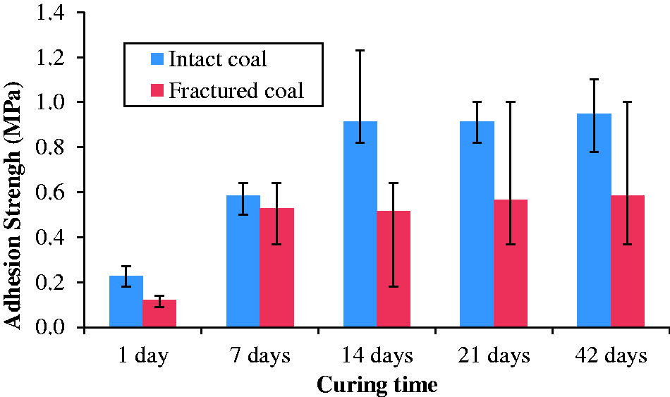
The adhesion test can fail in several ways. These include failure between the liner and the host rock (which is coal in this case), internal failure of the host rock, and debonding of the adhesive material between either the liner or the steel dollies (Gilbert et al., 2010; Saydam and Docrat, 2007). The percentage of coal on the failure surface for different curing time is shown in Figure 22. After seven days of curing, the failure mode for both intact coal and fractured coal is mainly attributed to the internal failure of the coal substrate. This indicates that the TSL material tested has very strong bond strength on coal and could be implemented for underground coal mining applications.
Percentage of coal on failure surface with different curing time.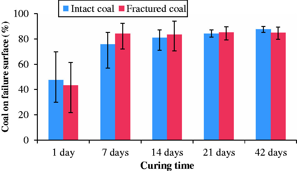
Conclusions
The permeability results show that the applied TSL can reduce the permeability of coal samples by at least two to three orders of magnitude for methane and carbon dioxide. The results have indicated the potential benefits of using TSL in coal mines as a gas management tool.
The application of TSL around the gas drainage holes can increase the drained methane purity and reduce the air contamination. Before TSL application, there were serious air leakages for holes 1 and 6, which lead to a low methane concentration. The TSL spraying had significantly improved the methane purity of these two holes, with the final methane purity about 80%. For other drainage holes with minor air leakage, the methane purity was not changed significantly.
The tested TSL is in the range of strong TSL based on the tensile strength results, with the final tensile strength reaching 3.5 MPa. The failure mode for the in-situ adhesion tests is mainly the internal failure of the coal substrate, which means the liner can bond well to the coal surface and could be implemented for underground coal mine applications.
The field trials showed the potential of using TSLs for gas management. However, there has been limited research in this area. It is obvious that further investigation is needed to see whether this technology can make a key impact on gas management in coal mines. Further to this research, the long-term performance of TSLs should be investigated. Improved techniques for measuring the flow rate need to be developed to remove the substantial variation in data.
The relationship between TSL application and coal gas outburst should also be investigated. Further field trials would include spraying TSLs on cleats intercepting with the drainage holes to investigate the sealing ability of the TSLs. A wider coverage area with TSL is also recommended to be conducted to see TSLs’ effect in reducing rib emissions.
Besides the benefits of TSLs for gas management, the application of TSLs could also bring many other benefits, such as for ground support and ventilation benefits. A financial and technical model should be built to evaluate the cost benefits of TSLs to determine the applicability of TSLs for underground coal mine applications.
Footnotes
Acknowledgements
The authors thank Mr Kanchana Gamage from the School of Mining Engineering UNSW Australia for his help and support. The authors would also like to thank Professor Alan Crosky from School of Materials Science and Engineering UNSW Australia for helping with the TSL tensile strength tests.
Declaration of conflicting interests
The author(s) declared no potential conflicts of interest with respect to the research, authorship, and/or publication of this article.
Funding
The author(s) received no financial support for the research, authorship, and/or publication of this article.