
Abstract
Overheating in buildings can be mitigated during periods of excessively warm weather through the application of a night purge ventilation strategy. Building on the mathematical model of Waterson and Hunt (2024), we investigate the emerging field of hybrid ventilation – specifically the rates of airflow achieved by the simultaneous combination of ‘stack-driven’ natural displacement ventilation and a mechanical supply. Whilst the focus of Waterson and Hunt (2024) was specifically on predicting the time taken to complete a purge, herein we focus on airflow rates and in doing so elucidate the somewhat counter intuitive role that the mechanical supply has on the natural ventilation flow rates. Our results challenge the perception that a hybrid approach must be superior to both solely natural and mechanical strategies. Focusing on the variation in airflow rates during a hybrid purge, our model reveals: (i) a hybrid purge offers an improvement over a solely mechanical purge only during one of the two distinct flow regimes identified; and (ii) the manner in which the stack-driven and mechanical components combine is highly nuanced and cannot be predicted by the linear superposition of the constituent stack-driven and mechanical contributions.
Keywords
Practical application
This research is anticipated to be of direct interest to practitioners involved in the first-order design of hybrid ventilation systems. Expressions quantifying the airflow rates for a hybrid strategy are developed and explored, with these analytical solutions offering ventilation practitioners a rapid predictive capability.
Introduction
The use of purge ventilation can be an effective way to help maintain a comfortable thermal environment in buildings, especially during periods of excessively warm weather. This method of ventilation is particularly effective in buildings incorporating phase change materials1,2 or high levels of exposed thermal mass.3,4
The purging of excess heat from a room is generally accomplished by the introduction of cooler air from the external environment and the resulting expulsion of the warm air inside. The goal of the purge is to achieve, ideally in an energy efficient manner, a comfortable internal environment that enhances health, well-being and productivity.5,6 The purge routinely takes place at night when the external temperatures are typically at their coolest and, hence, is commonly referred to as a night purge.
Historically, purge ventilation has been accomplished by either natural or mechanical ventilation strategies. Natural ventilation strategies harness the wind- and/or temperature-induced (the ‘stack effect’) pressure differences to drive a flow of air. 7 Herein, we focus on purges in the absence of any wind assistance. Through appropriate design, the wind may be readily harnessed to enhance the stack-driven flow rates7,8 and so, in that sense, we consider what could reasonably be regarded as a ‘worst-case’ (lowest airflow rate) scenario in terms of the natural component. Mechanical ventilation makes use of electrically-powered fans to drive the movement of air. In practice, the fan voltage and, therefore, the rate of rotation, is unlikely to be varied during the purge. Accordingly, in this work we focus on modelling a mechanical system that supplies air from the exterior to the interior at a fixed rate of flow (m3s−1).
Natural and mechanical ventilation strategies have inherent and contrasting strengths and weaknesses. Natural strategies consume little or no energy, but are often perceived as being challenging to control given: (i) that the naturally-driven flow rates can fluctuate widely depending on the external and internal conditions;4,8,9 and (ii) the rate of natural purging slows during a purge both with the presence of an assisting wind 8 and without. 10 Conversely, mechanical strategies offer the potential to supply air at a nominally invariant rate, irrespective of routine variations in wind speed and external air temperatures, but with an inherent energy penalty. Moreover, installation, operation and maintenance costs can be high and poorly designed or managed mechanical systems often do not work as expected. 9
The focus of our work herein is on the emerging field of hybrid ventilation, specifically on the simultaneous combination of stack-driven natural ventilation with a mechanical supply fan. Hybrid ventilation is often perceived as a means of overcoming the aforementioned limitations of both natural and mechanical ventilation strategies. 11 Herein we challenge this perception by addressing the following questions: (i) whether the perception is correct that a hybrid approach is always superior to both solely natural and solely mechanical ventilation?, and (ii) to what extent does the mechanical supply assist the natural component?
Waterson & Hunt developed the first mathematical model for transient hybrid ventilation, with the focus being on quantifying the time taken to purge excess heat from a room by means of a mechanical supply at floor level combined with stack-driven natural displacement ventilation via vents in the floor and ceiling.
12
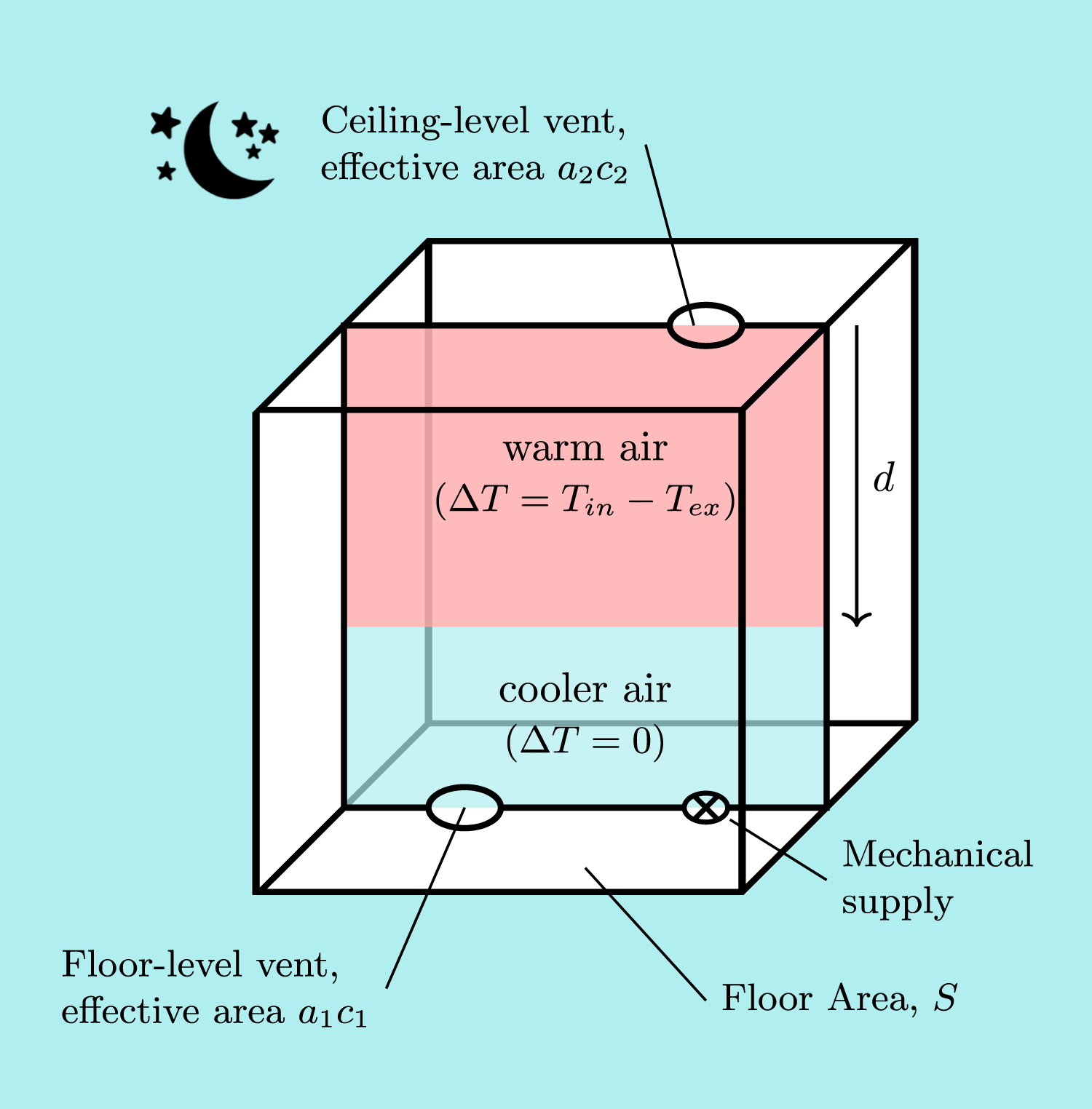
This arrangement is depicted in Figure 1. We showed that it is possible to develop analytical solutions for the resulting hybrid purge time. These predictions agreed closely with measurements from complementary laboratory experiments and, thereby, give confidence in the practical application (by, for example, practitioners, ventilation designers, etc.) of these solutions to guide first-order design. Annotated sketch of a room with floor area S. A vertical section is highlighted, with red shading indicating the excessively warm air (of temperature T
in
) to be purged and blue shading the cooler incoming air at the external air temperature (T
ex
).
Rather than being a straightforward extension to the theory that underpins a natural purge, the work of Waterson & Hunt revealed hybrid behaviour to be highly nuanced.
12
Indeed a hybrid purge was shown, through both theoretical and experimental developments, to typically take place across two distinct flow regimes: a ‘forward flow’ (FF) regime and a ‘reverse flow’ (RF) regime – shown in Figure 2. The analytical solution for the time taken to complete a purge is then the summation of the elapsed time in each regime. Waterson & Hunt’s mathematical model reveals that the time to complete a hybrid purge depends primarily on two ratios, (i) the mechanical supply flow rate relative to the initial natural stack-driven flow rate (a ratio we denote as Schematics showing a vertical section through a room subjected to a hybrid purge. The purge commences at time t = 0 and the room is shown at times t < t
rev
, t = t
rev
and t > t
rev
, where t = t
rev
represents the instant of flow reversal through the floor-level vent. For t < t
rev
, the direction of airflow through the vents is characteristic of the FF-regime. At t = t
rev
, the instant of transition between the flow regimes, there is no airflow through the floor-level vent. For t > t
rev
, the direction of airflow is characteristic of the RF-regime.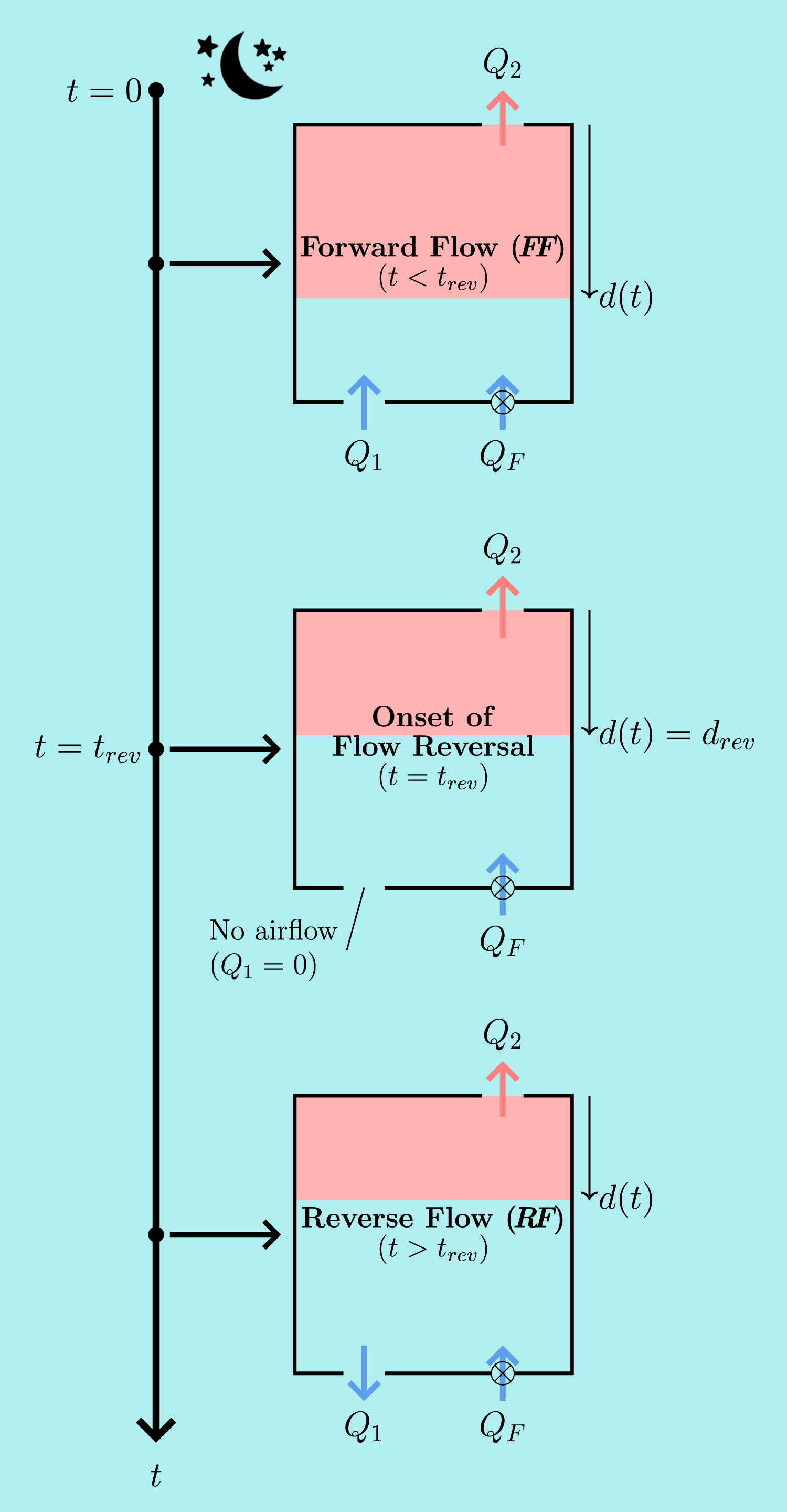
Expanding on the work of Waterson & Hunt,
12
our focus herein is instead on analysing and explaining the airflow rates through the vents during a hybrid purge. We reason that this analysis is instrumental to our fundamental understanding of hybrid flows given it reveals the (somewhat counter-intuitive) role that a mechanical supply has on the natural component of the flow. Moreover, through this analysis we provide new insight into: (i) the transition between the FF- and RF-regimes; and (ii) the relationships between the airflow rates through each vent and the governing ratios
Mathematical model for a hybrid purge
Consistent with the case considered by Waterson & Hunt,
12
we consider the purging of excess heat from a single room of uniform cross-sectional area S, as depicted in Figure 1. The excess heat takes the form a layer of warm air with a uniform temperature T
in
and an instantaneous depth d(t), where t denotes the time since the start of the purge. The external environment is at a uniform temperature T
ex
, where T
ex
< T
in
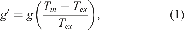
. Thus, the buoyancy (or ‘reduced gravity’) of the warm interior air relative to the cooler exterior air is

Given our focus on a night purge, the room is considered to be unoccupied and not subject to any active heat input, for example from lighting, computer equipment, radiators or underfloor heating, or solar heat gains.
Regarding notation, consistent with that adopted in earlier mathematical studies of steady-state and transient hybrid ventilation flows,12,13 quantities relating to the vents are given the subscripts (⋅)1 for the floor-level vent and (⋅)2 for the ceiling-level vent, and those relating to the mechanical system are identified by the subscript (⋅)
F
, the latter reading ‘forced’. Accordingly, a1 denotes the area of the floor-level vent and a2 the area of the ceiling-level vent. When considering the natural displacement ventilation component of the hybrid flow in isolation, the areas of these vents may be expressed (following, for example, Hunt & Linden
8
and Coffey & Hunt
14
) in terms of an overall effective vent area for the room
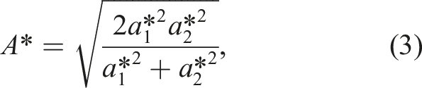

In (4), c1 and c2 are the (dimensionless) loss coefficients associated with the flow through the floor-level and ceiling-level vent, respectively. 1 Figure 2 illustrates this notation, showing the direction of the flow rates Q1 (m3s−1) and Q2 (m3s−1) through the vents. The (invariant) direction of flow from the mechanical supply Q F is also indicated. As anticipated in practice, the mechanical supply is maintained at a fixed flow rate, i.e. Q F is constant.
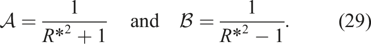
At this stage it is convenient to define the ratio of effective areas, R*, as
Modelling assumptions
The key assumptions used in the development of our mathematical model for hybrid ventilation are consistent with those which underpin the current industry guidance for the first-order design of natural ventilation strategies, for example CIBSE’s AM10,
15
as well as a substantial body of works that centre on modelling aspects of natural ventilation, for example.7,8,10,16,17 These key assumptions may be summarised as follows: (1) The internal and external air pressures vary hydrostatically; (2) The air is treated as incompressible; (3) The small differences in density between the warm and cool air mean that the Boussinesq approximation can be applied, see Supplemental Appendix 1 for details; (4) The flow is treated as being quasi-steady, allowing the application of the steady form of the Bernoulli equation at a given instant in time; (5) The room is considered to be perfectly insulated, such that there is no heat transfer between the air and the building fabric. (6) The loss coefficients remain constant throughout the purge.
18
The reader is referred to the work of Waterson & Hunt 12 for further details and justification.
In addition to the assumptions outlined above, the modelling herein relies on a displacement flow being maintained – thereby necessitating the absence of: (i) an exchange flow through the ceiling-level vent; (ii) interfacial mixing resulting from the mechanical supply; and (iii) interfacial mixing from the inflow through the floor-level vent. Hunt & Coffey 19 demonstrate experimentally that exchange flow is avoided if the ratio of inertial to gravitational forces, expressed as the Froude number Fr2, at the ceiling-level opening exceeds the critical value of 0.33 – hence, herein we require Fr2 > 0.33. Their research also reveals that interfacial mixing occurs if the Froude number associated with the inflowing air at the level of the interface Fr i exceeds the critical value of 0.67 – hence our requirement to prevent interfacial mixing necessitates Fr i ⩽ 0.67. The reader is referred to Supplemental Appendix 2 in Waterson & Hunt for further details. 12
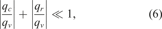
In the event that, contrary to our assumption of perfect insulation, there are radiative and convective heat transfers between the thermal mass of the room surfaces and the interior air, then the natural component will be enhanced, increasing the rate of outflow and delaying the onset of reversal. However, we envisage that heat transfer from thermal mass within the room will not play a significant role in the purging of warm air if the radiative and convective heat fluxes from the thermal mass to the air are small in respect to the advective heat flux from ventilation. This criterion can be expressed as
Model development for a hybrid purge
Flow rates through the vents
Following the approach of Waterson & Hunt,
12
we derive (see Supplemental Appendix 1) the following quadratic polynomials for the flow rate through the floor-level vent, Q1, in the FF- and RF-regimes
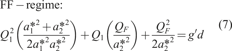
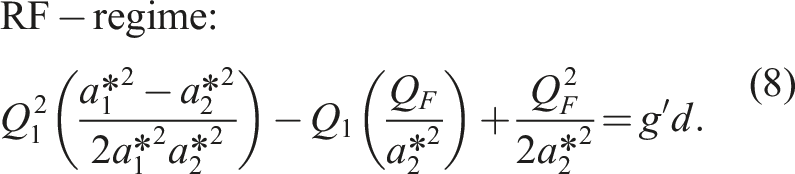
Note the changes of sign in the coefficients of the quadratic and linear terms in (8) relative to those in (7).
The quadratic polynomials for Q2 are derived from (7) and (8) by applying the principle of conservation of volume for an incompressible flow to a control volume coincident with the perimeter of the room, namely


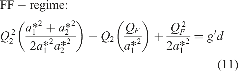
Clearly, from (9) and (10), the airflow rates through the vents are equal, i.e. Q1 = Q2, only for the case when there is no mechanical supply flow rate (Q F = 0) and the purge is in the FF-regime.
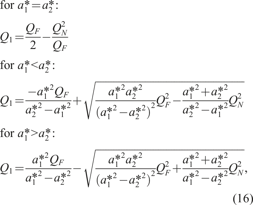
Solving (7) and (11) yields the following hybrid flow rates through the floor-level and ceiling-level vents in the FF-regime
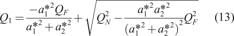
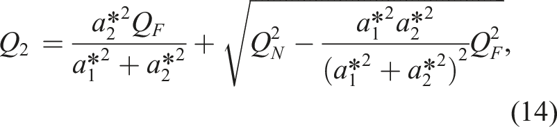

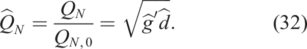
Being non-physical, the other solutions to the quadratic equations are neglected. With reference to, for example, Linden et al. 10 it is evident that the quantity Q N in (15) is the instantaneous stack-driven airflow rate, i.e. the flow rate which would be achieved in a solely natural (non-hybrid) purge.
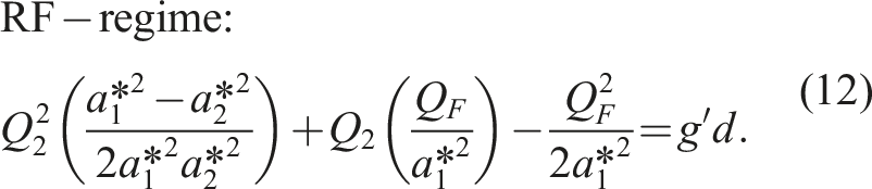
Similarly, from (8) and (10), the hybrid flow rates through the vents in the RF-regime are
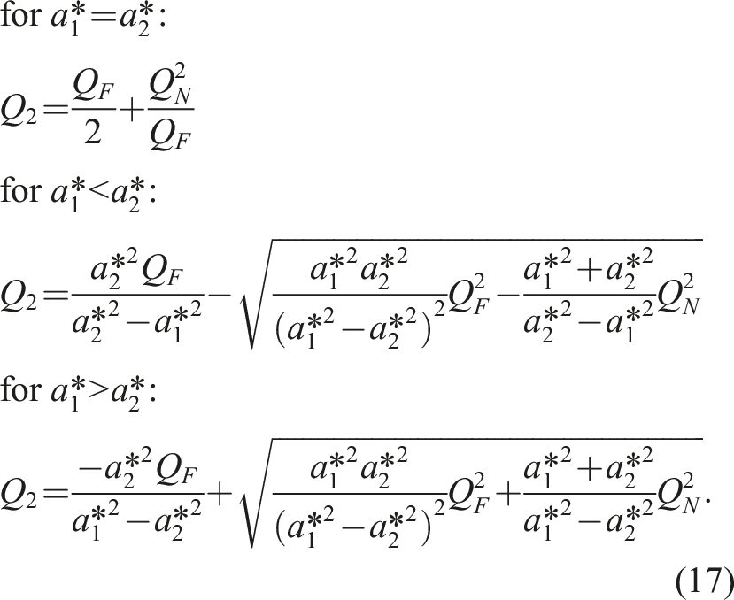
Note that, unlike the solutions for the FF-regime, the form of the solutions for the RF-regime depends on the relative magnitude of
Onset of flow reversal
A reversal in the direction of flow through the floor-level vent compared with that of a solely natural purge was always observed during the experiments conducted by Waterson & Hunt that commenced in the FF-regime. 12 For ‘modest’ 2 mechanical supply flow rates defined in (21), experimental observations showed flow directions consistent with the timeline shown in Figure 2. Initially (when d > d rev ), inflow was observed through the floor-level vent, with this transitioning to sustained outflow at later times (when d < d rev ). At the instant of transition, the time is denoted t rev and the layer depth d rev . By contrast, for mechanical supply flow rates exceeding a critical value (that Waterson & Hunt quantified and expressed as QF,crit 12 ), outflow was observed through both floor- and ceiling-level vents for the entire purge, i.e. the hybrid purge commenced, and continued, in the RF-regime.
At the instant of transition, there is no flow through the floor-level vent (Q1 = 0) and, hence, volume conservation (9) dictates that Q2 = Q F . This is identical to the rate of outflow of a solely mechanical purge, hence no benefit is derived from the stack-driven component at the instant of transition. Indeed, Q2 ⩽ Q F for the entire duration of the RF-regime, such that (somewhat counter-intuitively) the rate of outflow of warm air could be increased to Q F by closing the floor-level vent for t ⩾ t rev .
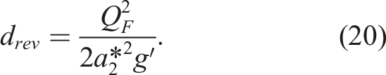
Substituting Q1 = 0 into (13) or (16) and rearranging yields the flow rate through the ceiling-level vent at the onset of reversal

This reveals that, somewhat surprisingly, the onset of flow reversal is independent of the area of the floor-level vent. This is not explicit in other works on hybrid ventilation,12,13 the criteria for reversal being defined therein only as a function of both A* and R*.
The form of

Upon analysing (19) and (18) we deduce that, for hybrid purge ventilation, the direction of flow through the floor-level vent reverses when the flow rate through the ceiling-level vent exceeds the maximum possible natural flow rate through that opening.
Criterion governing the flow regime at the onset of the purge
The purge is in the FF-regime when d > d
rev
and in the RF-regime when d < d
rev
, where, on rearranging (18)
It then follows that the purge will commence, and continue, in the RF-regime if d
rev
> d0. Thus, the purge commences in the RF-regime for mechanical flow rates that exceed

Non-dimensionalisation & governing parameters
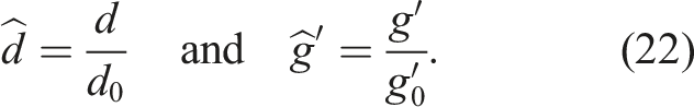
Following Waterson & Hunt, 12 we now choose characteristic quantities with which to non-dimensionalise the solutions for the flow rates through the vents, (13), (16), (14) and (17).
Using d0 as the characteristic length scale and
Non-dimensionalising in this manner facilitates comparisons with the natural ventilation purge and between hybrid purges with different opening areas.
The time taken to purge by natural displacement ventilation,
10
namely
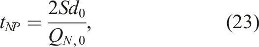

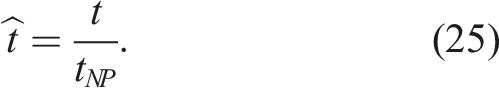
Accordingly, dimensionless time is defined as
The non-dimensional initial conditions are therefore

Thus, the purge commences when
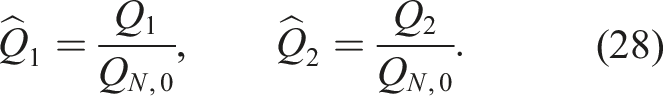
Upon non-dimensionalising the solutions, (13), (14), (16) and (17), the following non-dimensional flow rates are produced
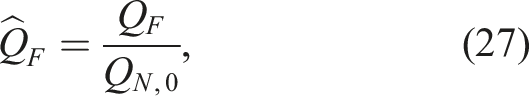
The dimensionless mechanical forcing,
The dimensionless geometric parameter R*, (5), is shown by Waterson & Hunt to control, alongside the governing parameter
The ambivalent nature of mechanical assistance
The behaviour in the forward flow regime
Converting (13) and (14) into non-dimensional form yields
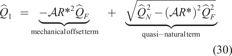
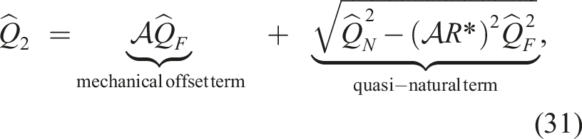
A comparison of the forms of (30) and (31) with (32) reveals that hybrid purge ventilation is fundamentally different to the natural purge. From (30) and (31), the flow rate through each vent during the hybrid purge is the summation of a ‘mechanical offset term’,
This behaviour demonstrates the duality which arises from introducing a fixed mechanical supply flow rate to a naturally ventilated room. The mechanical forcing provides a constant boost to
At first sight, the combination of natural displacement ventilation and an imposed mechanical supply flow rate might be considered as being analogous to the scenario of a room ventilated using natural displacement ventilation with an assisting wind. If this were the case, then, following Hunt & Linden,
8
the overall flow rate through the room could simply be expressed in the same form as a purely stack-driven flow, but with a virtual warm air layer depth
The behaviour in the reverse flow regime
Converting (16) and (17) to the non-dimensional form yields
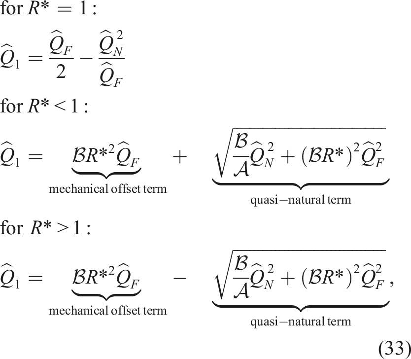
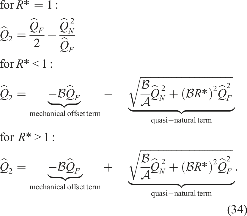
For R* ≠ 1, the flow rates through the vents can be expressed in the same form as for the FF-regime, i.e. as the summation of a mechanical offset term,
Conversely, for R* = 1 there is no quasi-natural term. Instead, the flow rate through each vent is equal to one half of the mechanical flow rate with an offset of magnitude
As for the FF-regime, the relationships between the flow rates through the vents and the dimensionless mechanical forcing is non-trivial and evidently cannot be predicted by the simple superposition of the natural and mechanical flow rates calculated in isolation.
Flow rate variations with warm air layer depth
We now investigate the variations in the flow rates as the depth of the layer of warm air decreases. Figure 3 plots Variation in the flow rates through the vents with warm air layer depth. Solid lines indicate the FF-regime, dashed lines the RF-regime and crosses the onset of flow reversal. The grey shaded region shows 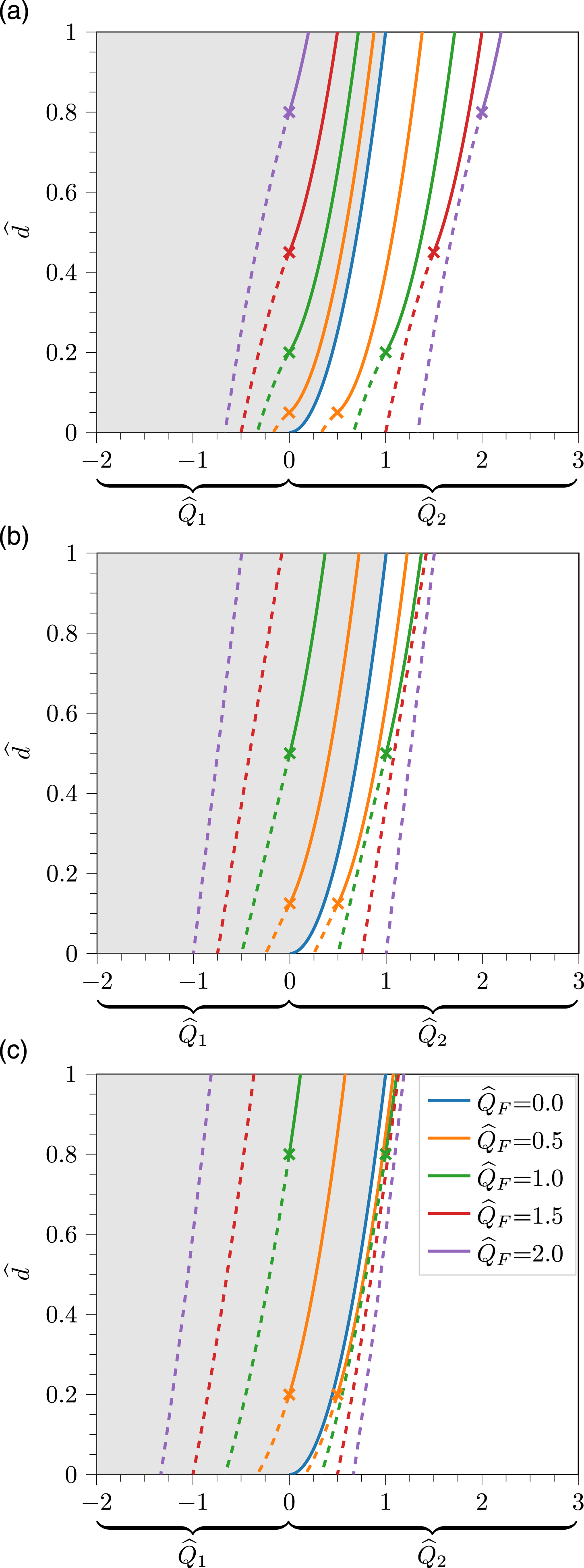
For the natural case (i.e. for
Increasing the dimensionless mechanical forcing
Comparing Figure 3(a)–(c), over which R* increases by a factor of four, it is evident that the value of R* has a profound influence on the flow rates achieved during a hybrid purge. The predictions plotted in Figure 3 imply that decreasing only the value of R* (i.e. increasing the area of the ceiling-level vent relative to the area of the floor-level opening such that A*, QN,0 and, hence,
During the FF-regime, the flow rate through the ceiling-level vent always exceeds the mechanical supply flow rate
In natural displacement ventilation (e.g. Etheridge & Sandberg
18
), the inflow through the floor-level vent exactly matches the rate of outflow through the ceiling-level vent (Q1 = Q2 ⇒ Q1/Q2 = 1). However, this is not the case for hybrid ventilation. Figure 4 plots the ratio of the flow rates through the vents in the floor and ceiling against the depth of the layer of warm air, from (30), (31), (33) and (34) – note that negative values of 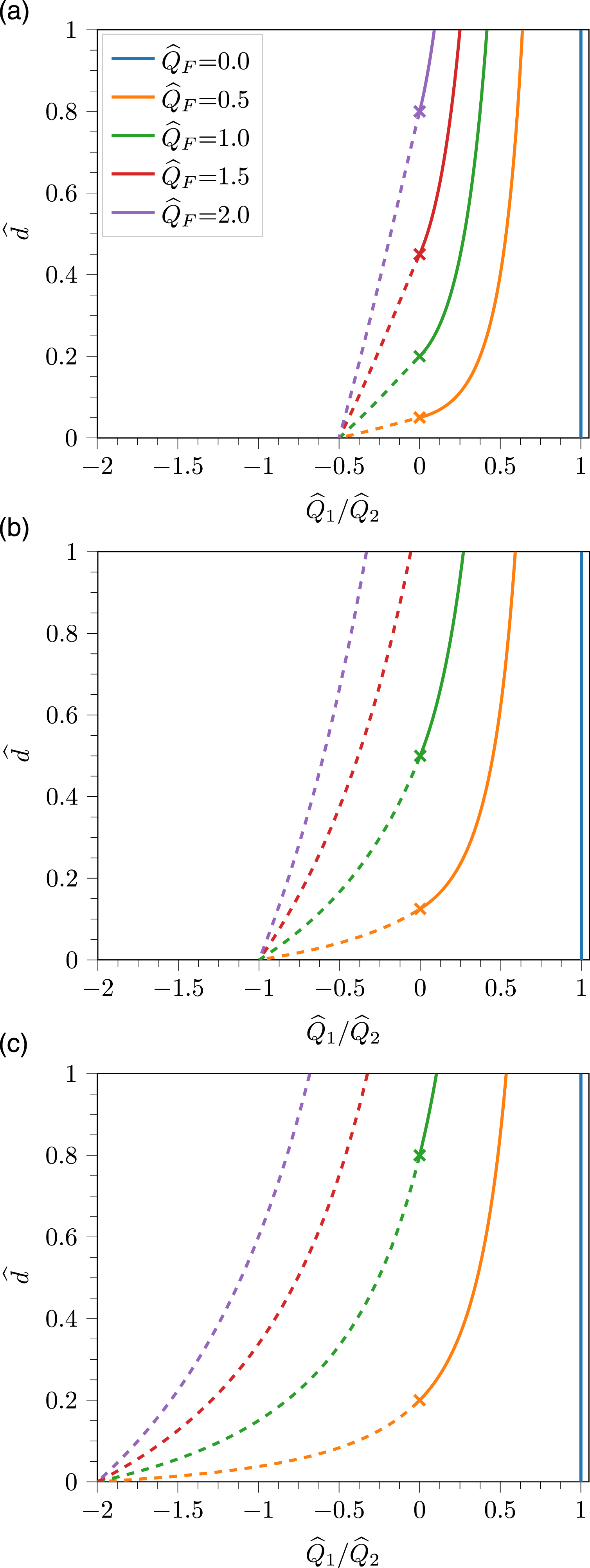
Irrespective of the values of
This can be explained by considering that at the completion of the purge there is no warm air inside the room and, therefore, no stack-driven pressure differences across the vents. Instead, the flow rate from the mechanical supply is simply distributed between the ceiling-level and floor-level vents depending on how restrictive these vents are to the flow of air (see Supplemental Appendix 4 in Waterson & Hunt 12 ).
The fallacy of prediction by flow rate superposition
From sources within the hybrid ventilation industry, we understand that, at the time of writing, practitioners routinely estimate the flow rates of a hybrid system by: (i) calculating the natural component in isolation; and (ii) adding this natural component directly to the mechanical supply flow rate. We refer to this approach hereinafter as the method of superposition. Much as for the wind-assisted 7 and wind-opposed 20 natural ventilation scenarios, the mechanical and natural components of a hybrid system do not superpose additively to yield the total flow rate. This is a direct consequence of the non-linear relationship between pressure and velocity as is evident in the Bernoulli equation.
Our results highlight that the rate of outflow calculated using superposition is always an over-prediction. As the quality of the internal environment is intrinsically linked to the rate of ventilation, 3 over-predicting the flow rate at the design stage will lead to a poor design in practice. While our focus has been on purge ventilation, this finding is equally valid for steady-state scenarios in which the depth of the layer of warm air remains constant.
From the work of Waterson & Hunt, the rate at which excess heat is purged from a room is proportional to
Based on this definition,
Figure 5 shows the variation of Variation in the ratio of the flow rate through the ceiling-level vent to the flow rate derived by simple superposition of the natural and mechanical flow rates calculated in isolation from (36). Solid lines indicate the FF-regime, dashed lines the RF-regime and crosses the onset of flow reversal. (a) R* = 0.5, (b) R* = 1.0, (c) R* = 2.0.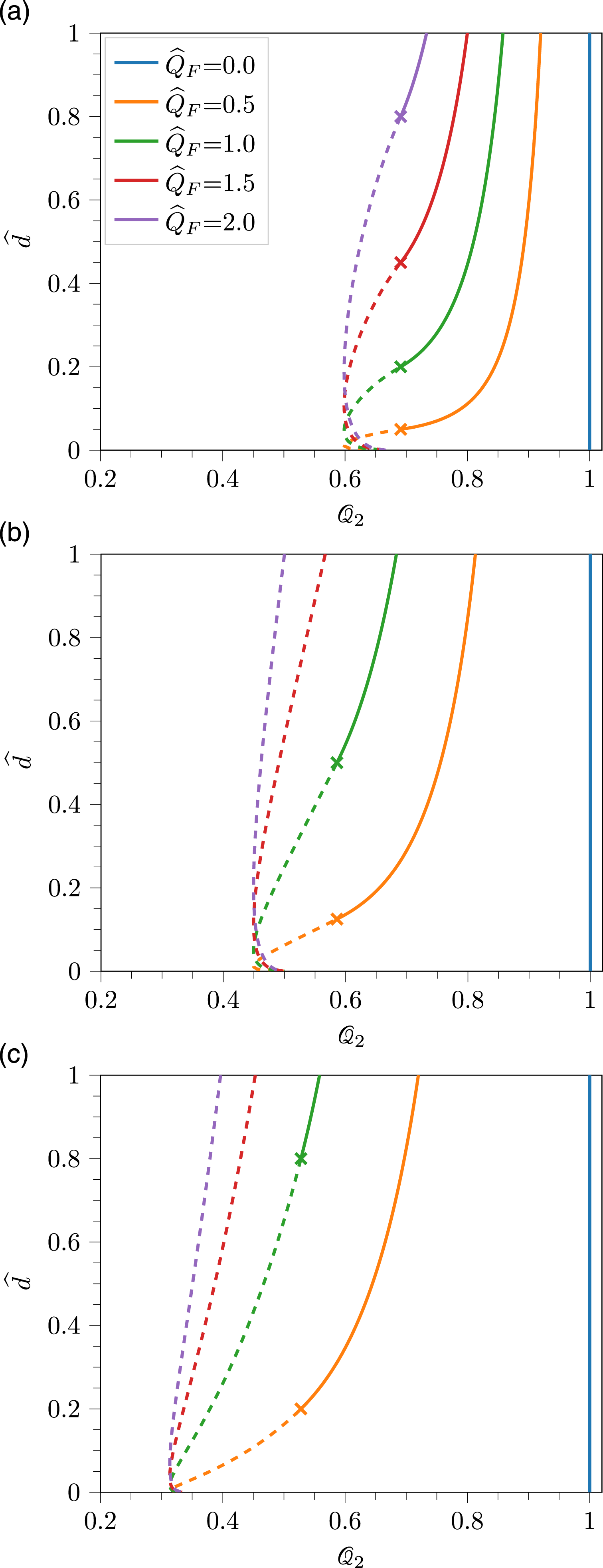
As

Qualitatively, from Figure 5, the minimum value The variation in the 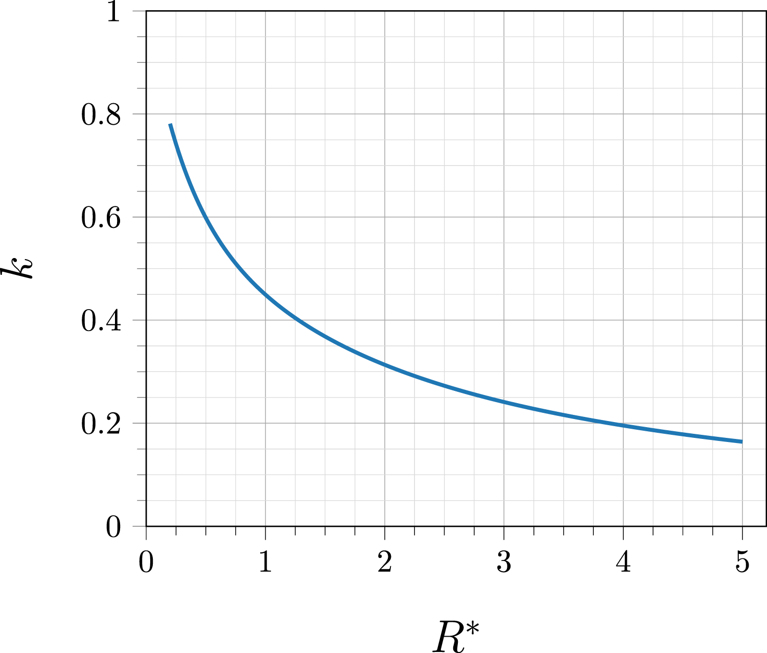
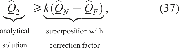
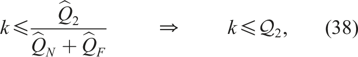
A typical design has 0.5 < R* < 2, leading to 0.3 < k < 0.6 on reading from Figure 6. This range of k highlights just how significantly the uncorrected superposition method overpredicts the rate of outflow through the ceiling-level vent, with the flow rate being less than one half of the value predicted by superposition for R* ≳ 0.75. Any practitioners calculating hybrid flow rates using simple superposition, either directly in their hand calculations or embedded within software packages, are therefore strongly advised to instead make use of the analytical solutions for the flow rates provided herein, i.e. (13), (14), (16) and (17), or to apply the relevant correction factor from Figure 6. The values of k shown in Figure 6 satisfy (38) for all values of
Approximating the flow rate through the ceiling-level opening as
Flow rate approximations
With a focus on the rate of outflow through the ceiling-level vent and with a view to enhancing our fundamental understanding of hybrid ventilation flows, hereafter we derive approximations for
(a)

Therefore, for
(b)
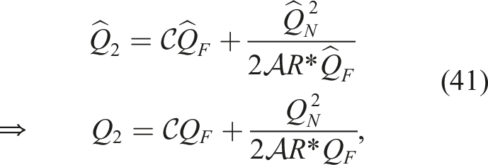
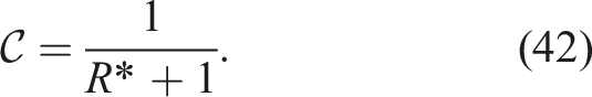
While (41) is an approximation for R* ≠ 1, for R* = 1 it reduces to the analytical solution (34). In (41), the term
Approximations to the hybrid purge time can be derived from these flow rate approximations, as shown in Supplemental Appendix 3. Good agreement with the full analytic solution (see equation (48) of Waterson & Hunt
12
) is obtained for the small
Geometric analogies – hybrid ventilation triangles
In the development of our mathematical model, we highlight that the mechanical and natural components of a hybrid system combine in a complex manner, with the mechanical supply simultaneously assisting and opposing the stack-driven flows. We also highlight, for example in Figure 5, that simply summing the mechanical and natural components calculated in isolation is erroneous and significantly overestimates the flow rates through each vent. Inspired by the ‘natural ventilation triangle’ aide-memoire 4 of Hunt & Linden, 8 and with the aim of clarifying the manner in which the mechanical and stack-driven components combine, we now present geometric analogies for the (dimensional) flow rates through the vents in terms of R*, Q F and Q N .
By presenting the combination of the natural and mechanical components in a geometric manner, i.e. in the form of scaled diagrams, we envisage that readers and practitioners will find it easier to visualise and understand the influence of R* (through
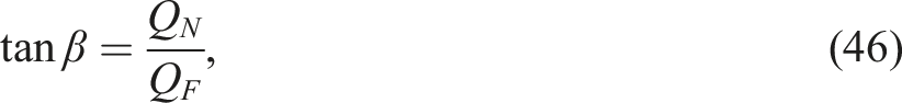
Considering the FF-regime, from (14) the underlying equation describing Q2 can be written as follows
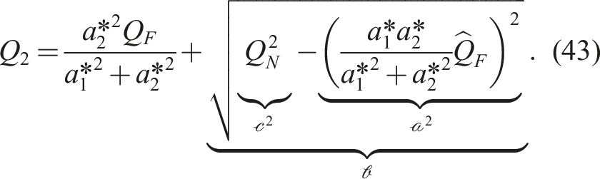
For a right-angled triangle with hypotenuse of length
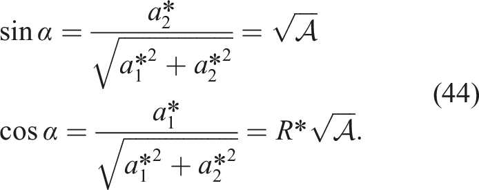
Figure 7 shows the variation in α with R*, demonstrating that as R* increases α decreases, and vice versa.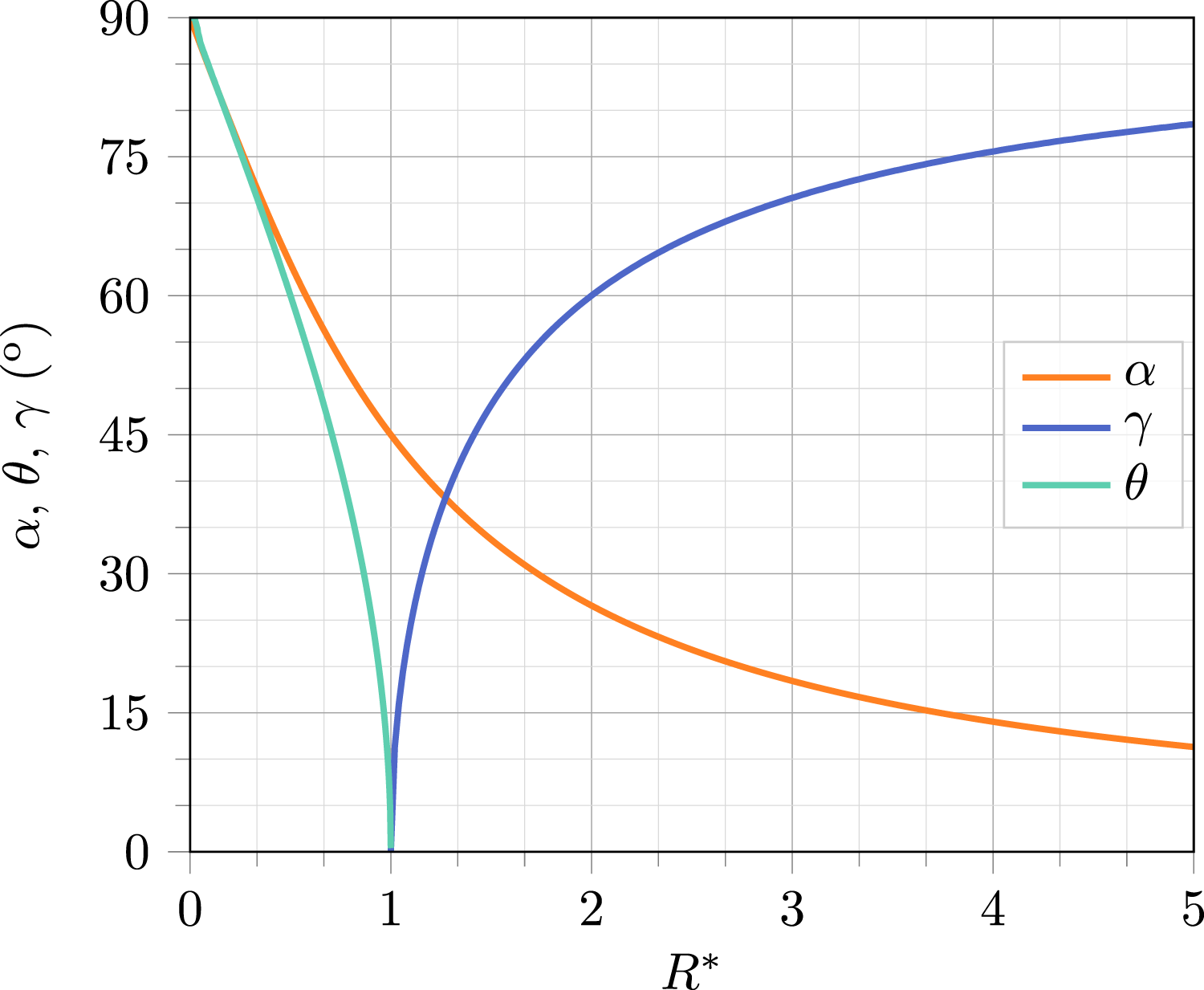
Using the trigonometric identities from (44), the solution for Q2 in the FF-regime, (43), can be rewritten as

With knowledge of Q
N
, Q
F
and R*, ‘hybrid ventilation triangles’ showing the values of Q1 and Q2 in the FF-regime can be constructed using (44) and (45) as follows. (1) From the origin, point O, draw a vertical line along which the lengths Q2 and Q1 will lie. (2) Calculate the angle α from (44). (3) Draw a construction line from O at an angle (90 − α) degrees from the vertical. (4) Draw a straight line of (scaled) length Q
F
from O at an angle of 2(90 − α) degrees from the vertical. The end of this line is labelled point A. (5) Draw a straight line joining A to the construction line at point B, such that the angle ∠OAB is α and the angle ∠ABO is 90°. (6) Draw a straight line from point B which meets the vertical at point C such that the angle ∠OBC is α and the angle ∠BCO is 90°. (7) Draw a straight line of (scaled) length Q
N
joining B to the vertical at point D. (8) The length OD is then Q2. (9) Draw a circular arc about the origin O which joins A to the vertical at point E. (10) The length ED is then Q1.
Figure 8 shows the resulting hybrid ventilation triangles for the FF-regime for R* = {0.5, 1.0, 2.0}. Comparing Figure 8(a)–(c), as R* increases (i.e. from Figure 7, α decreases), the contribution of the mechanical forcing to the flow rates through both the floor-level and ceiling-level vents decreases – indicated diagrammatically by the increase in angle between Q2 and Q
F
. As the purge progresses, the depth of the layer of warm air decreases and therefore the stack-driven (natural) component, Q
N
, decreases. In Figure 8, a decrease in the length Q
N
acts to point D vertically downwards, decreasing both Q1 and Q2.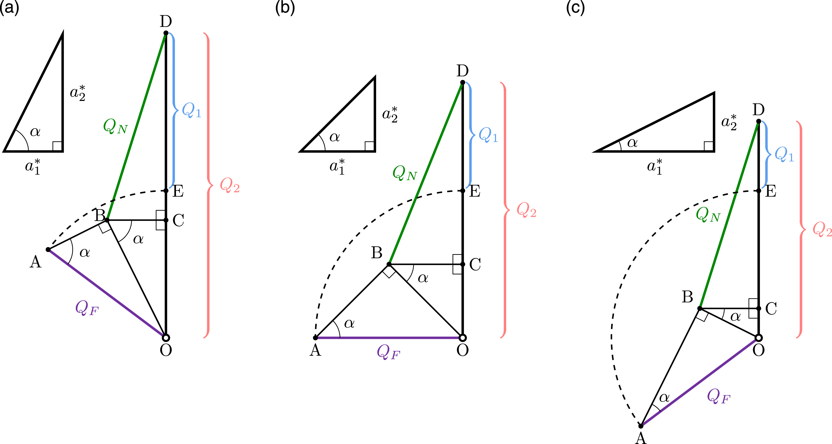
Flow reversal occurs when the natural component is reduced such that Q2 = Q F and Q1 = 0. The position of point D at the instant of reversal is indicated in Figure 8 by point E (the black dot where the dashed arc of radius Q F meets the vertical). From a comparison of Figure 8(a) and (c), it is apparent that this reversal in flow direction will occur at larger values of Q N if R* increases.
The behaviour in the RF-regime is more complex than the FF-regime, with the equation for
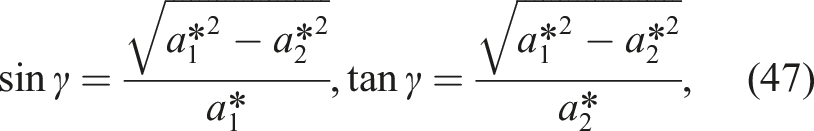
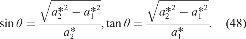
For reference, the values of γ and θ as a function of R* are shown in Figure 7, with θ valid only for R* ⩽ 1 and γ valid only for R* ⩾ 1. As R* decreases below R* = 1, θ increases, whereas γ increases as R* increases from R* = 1.
Applying the trigonometric identities from (46)–(48) to (34), the flow rate through the ceiling-level opening in the RF-regime is given by
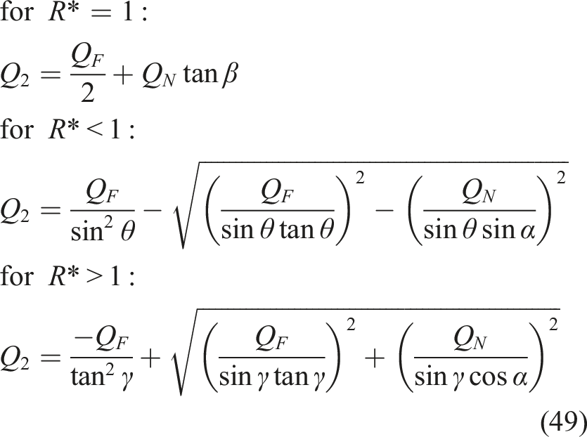
The flow rate through the floor-level vent can be determined from (49) by applying the equation for volume conservation in the RF-regime, (10). Evidently, from (49), a different set of hybrid ventilation triangles is required depending on the value of R* with respect to unity.
Using (46)–(48) and (49) and a similar methodolgy to that applied in the FF-regime, Figure 9 depicts the combination of the stack-driven and mechanical components in the RF-regime in the form of hybrid ventilation triangles. In the RF-regime, volume conservation dictates that Q
F
= Q1 + Q2, indicated by the dashed arcs. Therefore, as depicted in Figure 9, the stack-driven component influences only the distribution of the mechanical flow rate across the vents – whereas in the FF-regime, increasing Q
N
increases both Q1 and Q2 and decreasing Q
N
decreases both Q1 and Q2.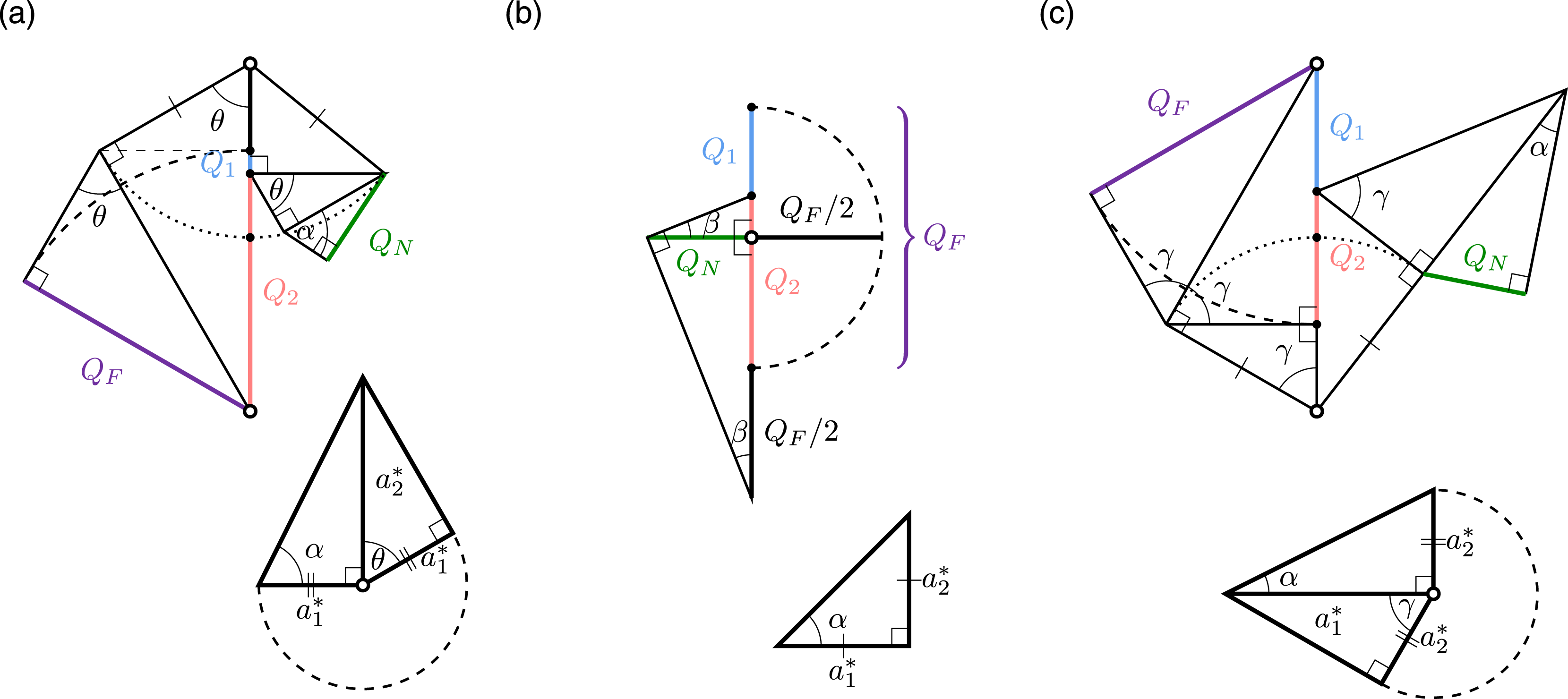
In contrast to the diagrams for the FF-regime which require only a single angle α, the solutions for the RF-regime are functions of α and the angles θ (for R* < 1), γ (for R* > 1) or β (for R* = 1).
Comparing Figure 9(a)–(c), a lower value of R* results in a larger flow rate through the ceiling-level opening and therefore warm air is purged at a greater rate (as for the FF-regime). For Figure 9(a)–(c), as Q N decreases the point dividing Q1 and Q2 slides vertically downwards, increasing Q1 and decreasing Q2. Volume conservation in the RF-regime, (10), shows that the summation of Q1 and Q2 is equal to the mechanical supply flow rate.
Conclusions
Hybrid ventilation is often perceived as being superior to both mechanical and natural ventilation, however, our results challenge this notion. Expanding on our previous study of hybrid ventilation, 12 wherein the focus was on the analytical determination of the time taken to complete a hybrid purge, herein we quantify and analyse the airflow rates produced during a hybrid purge. Whilst presented in the context of a hybrid purge, our analysis is of more general application given it elucidates, from first principles, how the natural and mechanical supply flow rates combine. The system considered comprises the simultaneous operation of a (constant flow rate) mechanical supply and (time-varying) stack-driven natural displacement ventilation via vents at floor and ceiling levels. Our analysis follows within the same framework of simplifying assumptions that underpin the current industry guidance for practitioners, and therefore we anticipate that our results will be welcomed by practitioners concerned with the application of hybrid ventilation to modern highly-insulated buildings.
The hybrid purge takes place across two distinct flow regimes (so-called ‘forward’ and ‘reverse’ flows), and our analysis shows that only during the initial forward flow regime can the rate of outflow of warm air exceed the flow rate of the mechanical supply. In the reverse flow regime, only a fraction of the mechanical supply contributes to the purging of warm air from the room – the remaining mechanically-supplied air being ‘short-circuited’ out through the floor-level opening. We may conclude then that in the reverse flow regime, hybrid ventilation is less effective than a purely mechanical system given that for the latter the rate of outflow of warm air is equal to the mechanical supply. Moreover, this finding implies that hybrid purge strategies which operate predominantly in the reverse flow regime will require more time to complete a purge and consume more energy (energy is needed to drive the mechanical supply of air into the room) compared with a solely mechanical purge.
The manner in which the stack-driven natural and mechanical components combine to yield the overall hybrid rate of airflow through the vents is shown to be complex. Indeed, the mechanical supply simultaneously assists, at the ceiling-level vent, and opposes, at the floor-level vent, the stack-driven flow. Importantly, the hybrid flow rate is not given by, or generally well-approximated by, the summation of the natural and mechanical components calculated in isolation. We highlight that hybrid airflow rates calculated through such a summation (or superposition) are overestimates of the true hybrid flow rates. This finding applies to both steady-state and transient flows. This erroneous method of superposition is widely used in industry and, given our findings, we strongly recommend that practitioners instead deploy the analytical solutions developed herein for the calculation of hybrid airflow rates. If the practitioner is insistent on the use of superposition to estimate hybrid flow rates then applying the correction factor derived herein (a factor typically between 0.3 and 0.6 depending on the ratio of the floor- and ceiling-level vent areas, see Figure 6) will ensure their estimates no longer grossly overpredict the flow rates.
To expose how the natural and mechanical components do combine, we develop a visual aide memoire - referred to herein as a ‘hybrid ventilation triangle’. The construction of these triangles, following the step-by-step algorithm developed, highlights the influence of the ratio of the floor-level to ceiling-level vent areas, the mechanical supply flow rate and the stack-driven component on the rates of hybrid airflow. As such, these triangles can be constructed as a guide to assist understanding and preliminary ventilation design.
Supplemental Material
Supplemental Material - Night cooling by hybrid supply ventilation – analytical predictions of airflow rates and the ‘hybrid ventilation triangles’
Supplemental Material for Night cooling by hybrid supply ventilation – analytical predictions of airflow rates and the ‘hybrid ventilation triangles’ by Matthew Waterson and Gary R Hunt in Building Services Engineering Research and Technology.
Footnotes
Acknowledgments
MW is grateful for the support of the EPSRC through their studentship programme (ref: EP/T517847/1). GRH would like to extend his personal thanks to Prof.C.Middleton and the Laing O’Rourke Centre for Construction Engineering and Technology at the University of Cambridge. GRH is grateful for the financial support of Innovate UK (ref: 106163 Product Based Building Solutions – High Productivity Digital Integrated Assured DfMA for Lifecycle Performance) in collaboration with Laing O’Rourke.
Declaration of conflicting interests
The author(s) declared no potential conflicts of interest with respect to the research, authorship, and/or publication of this article.
Funding
The author(s) disclosed receipt of the following financial support for the research, authorship, and/or publication of this article: This work was supported by EPSRC (No. EP/T517847/1).
Supplemental Material
Supplemental material for this article is available online.
Notes
References
Supplementary Material
Please find the following supplemental material available below.
For Open Access articles published under a Creative Commons License, all supplemental material carries the same license as the article it is associated with.
For non-Open Access articles published, all supplemental material carries a non-exclusive license, and permission requests for re-use of supplemental material or any part of supplemental material shall be sent directly to the copyright owner as specified in the copyright notice associated with the article.