
Abstract
Many low-energy buildings rely on a night purge strategy during periods of excessively warm weather in order to flush out excess heat and thereby help prevent overheating on the following day. A typical purge utilises either a mechanical or a natural displacement ventilation strategy. However, we investigate purging by the simultaneous application of natural and mechanical ventilation, i.e. using a hybrid strategy. Hybrid ventilation is widely promoted as a means of overcoming the inherent limitations of both natural and mechanical ventilation, although relatively little is understood about its operation on a fundamental level. Such was the lack of knowledge on hybrid ventilation that even the time taken to complete a purge was not known at the outset of this work. Through the development of a mathematical model, supported by a series of laboratory experiments, we show that the time taken to purge a room using hybrid ventilation can be established analytically, and is controlled by two ratios: (i) the flow rate of the mechanical supply (the ‘forcing’) relative to the initial flow rate through the vents in the absence of mechanical forcing, and (ii) the ratio of the floor-level and ceiling-level vent areas. The analytical predictions show close agreement with our measurements. Supplementing a natural displacement ventilation strategy with even a modest mechanical supply can reduce significantly the time taken to purge warm air from a room. Some of the implications of our findings for preventing overheating in buildings by increasing the efficacy of a night cooling strategy are discussed. Practical Application This research is directly applicable to practitioners involved in the first-order design of hybrid ventilation systems – particularly designs which incorporate a ‘night purge’ regime. Governing equations are derived and the key parameters controlling the rate of purging of warm air are revealed, allowing informed first-order design decisions to be made without the need for expensive and time-consuming computational simulations.
Keywords
I. Introduction
Effective strategies for purge ventilation are crucial for maintaining a comfortable internal environment in many buildings during the summer months, particularly those incorporating phase change materials1,2 or with high levels of exposed thermal mass.3,4
In general terms, purge ventilation refers to the flushing of excessively warm, stale or polluted air from a room through the introduction of air from the external environment. For a successful purge, the external air should be cool and/or fresh compared with the internal air, so that purging improves the quality of the internal environment. Such improvements have been shown to enhance the health and well-being of occupants, 5 and to increase their productivity. 6 The purging of excessively warm air typically takes place at night – and hence is commonly referred to as a night purge – in order to take advantage of the lower external night time air temperatures and thereby maximise the cooling effect achieved during the purge.
Studies from around the world have shown that effective night cooling strategies that rely on the purging of warm air from buildings can reduce the amount of mechanical cooling energy required on the following day to maintain the thermal comfort of occupants. For example, Piselli et al. 7 study the simulated performance of typical mid-rise apartment buildings in different Italian cities and show that it is possible to reduce the cooling energy requirement of these buildings by between 22% and 60% through the use of phase change materials and a natural night cooling strategy. Shaviv et al. 8 demonstrate that even in a hot and humid climate, reductions in peak internal air temperature of 3-6°C are achievable in a “heavy constructed building”, i.e. a building with significant thermal mass, through the use of a natural night cooling ventilation strategy.
Historically, designers have relied on either natural or fully mechanical ventilation strategies as the means to purge excess heat from a room. Hybrid ventilation offers an alternative approach, with a well-designed hybrid system being perceived to embody the best elements of both natural and mechanical ventilation in terms of energy use, ventilation control, occupant comfort, and cost. 9 Despite the potential benefits, a survey of the literature reveals that little is known about the use of hybrid ventilation systems to purge air from a room – hence the focus of this work being on the the use of hybrid ventilation to implement a purge.
Hybrid purge ventilation is defined herein as the flushing of warm air from a room by the simultaneous use of natural displacement ventilation and a constant mechanical supply of cooler air from the external environment. This definition is fundamentally different to that of a ‘mixed-mode’ ventilation strategy. In a typical ‘mixed-mode’ strategy, ventilation is provided by either a mechanical system or via natural ventilation, with the choice of mechanical or natural ventilation provision being made based on measurements of the internal and external conditions. For example, a ‘mixed-mode’ strategy may utilise a mechanical ventilation system during the winter months and a solely natural ventilation strategy during the summer months. For the purposes of clarity, we refer to mechanical ventilation as being the provision of an unvarying volume flow rate of external air to a room using a fan or pump. Natural ventilation refers to the provision of external air to a room using the buoyancy force generated by differences in air temperature between the internal and external environments, i.e. by the ‘stack effect’. As there is no guarantee of an overnight breeze, our focus is on understanding a hybrid purge in the absence of wind. We consider the purge to be complete if all of the warm air in the room at the start of the purge has been replaced by air at the external air temperature.
The capability to perform rapid predictions, as would, for example, be afforded by an analytical description of hybrid purge ventilation, is essential to facilitate and expedite preliminary design. Moreover, analytical predictions can assist those using computational fluid dynamics (CFD) to design and study hybrid purge systems. For example, analytical predictions can provide initial estimates for the areas of the vents and the strength of the mechanical forcing (m3s−1) required to complete a purge in a given time period, thereby streamlining the CFD design process by reducing the number of iterations which must be computed before a final design solution is reached. Moreover, as we shall establish in §II.B, the development of analytical solutions for hybrid purge ventilation reveals the key parameters that control the purge and their interdependence – this knowledge offering the designer new insights that would not be as readily achievable using other approaches. Despite the potential benefits that a hybrid strategy may offer, based on a review of the available literature it is evident that the purging of excess heat from rooms by hybrid ventilation has not been previously modelled theoretically or considered in any detail by experiment or in numerical simulations. This provides the motivation for the current study.
Based on our survey of the open literature, we have identified a number of significant gaps in the current understanding of hybrid purge ventilation. These concern: (1) How the flow rate of the mechanical supply and the areas of the vents influence the rate of purging (§II.B.6); (2) How the rate at which excess heat is removed varies during a purge (§II.B.1) and therefore what controls the time taken to complete a hybrid purge (§II.B.7); (3) Whether a potentially undesirable reversal in the direction of air flow through the floor-level vent occurs during a purge. Indeed, in §II.B.4 we demonstrate that, somewhat counter-intuitively, the direction of flow will reverse before the purge is complete and there will always be part, or all, of a hybrid purge which takes place in this ‘Reverse Flow’ regime; and (4) How to guide a practitioner in the design of a hybrid purge ventilation strategy, given, to our knowledge, there is no existing guidance available.
Without bridging these gaps in knowledge, practitioners have no bespoke analytical framework on which to even begin designing a hybrid purge ventilation system, and little or no insight into whether their design will be efficient or even operate as intended. Herein we develop a mathematical model for predicting the purging of excess heat from a room by means of hybrid ventilation and, in doing so, are able to throw considerable light on these concerns. The primary purpose of the model we develop is to offer designers a rapid predictive capability for assessing how the time taken to complete a hybrid purge varies with the area of vents, the flow rate of the mechanical supply (sometimes also referred to as the ‘strength’ or ‘duty’), and the geometry of the room. The model also offers new insights into hybrid flows and addresses a number of fundamental questions. For example, a practitioner might reasonably enquire whether the purge time is halved if the flow rate of the mechanical supply is doubled, or whether the relative sizing of floor-level and ceiling-level vents influences the time taken to purge the room if the combined area of these openings is fixed. We address these and other questions that are likely to be of interest to a designer.
Figure 1 depicts the essential geometry investigated, in which a typical box-shaped room is to be purged of warm air by means of a mechanical supply of cool external air at floor level operating in tandem with a natural displacement ventilation strategy – the latter achieved by means of stack-driven flow through horizontal vents in the floor and ceiling, again connecting the interior to the same cooler external environment. Sketches of the basic room geometry under consideration. (a) The positions of the natural vents and the mechanical supply; (b) the direction of airflow through each vent and the thermal stratification in the forward flow (FF) regime; and (c) the reverse flow (RF) regime. The flow of warm/cool air is indicated by the red/blue arrows respectively.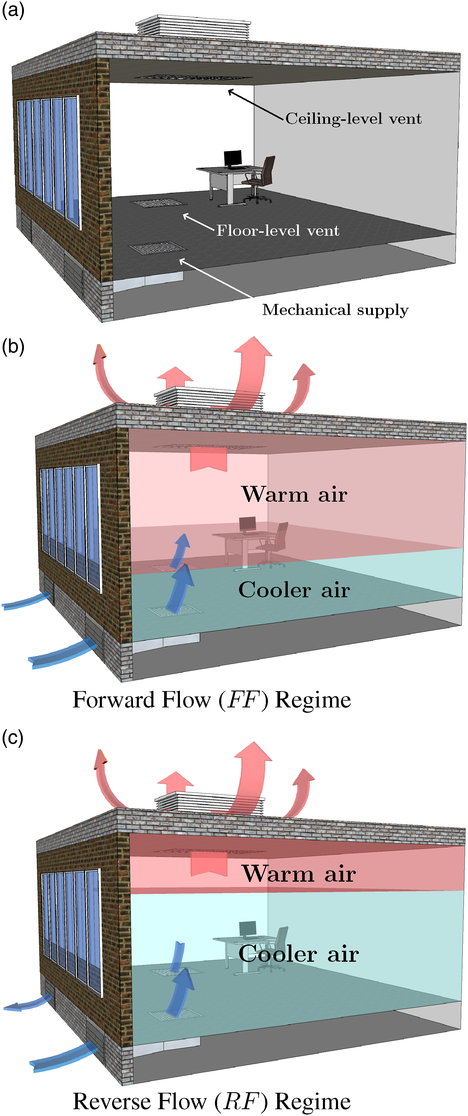
The mathematical model we develop for hybrid purge ventilation follows a tried-and-tested approach – an approach based on solving the underlying equations of fluid mechanics which describe the bulk motion of air by the natural and mechanical components that comprise the hybrid system. For natural ventilation, mathematical models developed following this approach now form the bulk of the relevant first-order design guidance written for practitioners, for example CIBSE’s AM10 10 and ASHRAE’s Design Guide for Natural Ventilation 11 . Working within the same framework of standard assumptions and justifiable simplifications that underpin this guidance for natural ventilation, in §II.B.3–II.B.7 we develop a suite of analytical solutions for hybrid purge ventilation, thereby facilitating rapid ‘hand’ calculations at the initial design stage. To our knowledge, the work presented herein is the first to mathematically model time-dependent hybrid ventilation, the previous theoretical works on hybrid ventilation focusing exclusively on the prediction of steady flows12–14. The aspects of these works on steady flows and of others pertinent to our theoretical developments are outlined below.
A number of studies have succeeded, through the use of simplified mathematical models, to enhance our fundamental understanding of purging by natural ventilation. For example, for a room with vents at high and low level, Linden et al. 15 predict the time taken to purge the room with the assumption that a displacement flow is maintained, and Wise and Hunt 16 quantify how this purge time is extended given that Hunt and Coffey 17 show that such a displacement flow must transition to an (unbalanced) exchange flow before the purge is completed. For solely high-level vents, Epstein 18 established the rate at which the air cools by balanced exchange flow in a room with a single high-level opening, and Kuesters and Woods 19 examine the formation and evolution of stratification during a purge facilitated by two or more high-level vents. Hunt and Linden 20 extend our predictive capability still further by developing a mathematical model for the stack-and-wind driven purging of air from a room. Notably, the wind influences the external pressures on a façade, thereby modifying the pressure differences that are established across the vents compared with a solely stack-driven flow. By contrast, for hybrid ventilation, the addition of a mechanical supply to an otherwise solely stack-driven flow increases the internal pressures relative to the those externally. Thus, a hybrid purge cannot be modelled by simply replacing the terms describing the wind-driven component of a stack-and-wind driven purge in the theoretical model of Hunt and Linden 20 with terms that describe the mechanical component of the hybrid system. This then provides further motivation for the current work.
The remainder of this paper is laid out as follows. Section II begins by outlining, with justification, the simplifying assumptions that underpin the development of the mathematical model for hybrid purge ventilation. The limiting case of a hybrid purge for which the strength of the mechanical supply is zero, i.e. a natural ventilation purge, is then discussed (§II.A) – this discussion being necessary to establish a reference flow rate and purge time with which to scale the results for the general hybrid case. The governing equations are then developed for the time-varying flow rates through each vent for hybrid purge ventilation (§II.B.1). After non-dimensionalisation (§II.B.2), these equations are solved to yield analytical solutions for the flow rates in the ‘forward flow’ and ‘reverse flow’ regimes (§II.B.3 and §II.B.5). Given our focus is to derive expressions for the time taken to purge a room using a hybrid system, we proceed by considering the onset of flow reversal (§II.B.4) rather than dwelling on the nuances of the time-varying flow rate through each vent – an in-depth analysis of the flow rates during the hybrid purge is the focus of a complementary paper by Waterson & Hunt 21 . Equations describing the time rate of change of the depth of the layer of warm air are then derived and solved analytically (§II.B.6). These solutions reveal the controlling parameters and their interdependence. A solution of immediate practical interest to practitioners is then explored, specifically the time taken to complete a hybrid purge, i.e. the ‘hybrid purge time’ (§II.B.7). The details of a complementary experimental campaign are outlined in (§III) before theoretical and experimental results are presented (§IV). Excellent agreement is found between the theoretical and experimental results. An analytical approximation of the overall purge time is then derived (§V) and example calculations are presented for the purging of a lecture room (§VI). Concluding remarks are made (§VII), highlighting some of the key implications of our results for hybrid ventilation design.
II. Mathematical model for a hybrid purge
To gain a first insight into hybrid night purging, we consider the purging of heat from a single room, of floor area S, rather than from interlinked rooms in a building. Lynch & Hunt 22 highlight the considerable added complexities which arise when purging heat naturally from multi-storey atrium buildings due to the interconnected nature of the geometry and unavoidable mixing. Consequently, a single room represents a logical starting point for the current study. Given our focus on a purge at night, the room is considered to be unoccupied and without any active internal heat sources (e.g. lights, computer equipment, radiators or underfloor heating) or solar heat gains.
Figure 2 depicts the basic room geometry considered. The layer of warm air has a temperature T
in
and depth d, and the cooler external air temperature is T
ex
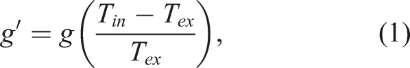
. As the timescale for purging by natural displacement ventilation (the worst-case scenario for this hybrid model) is generally significantly shorter than the timescale over which there is a significant variation in external air temperature, the temperature of the external air is considered to be constant for the entire duration of the purge. The difference in temperature between the warm internal air and the cooler external air, ΔT = T
in
− T
ex
is more conveniently expressed in terms of the buoyancy (or ‘reduced gravity’) of the warm air relative to the cooler external air: Annotated sketch of a typical room with floor area, S. A vertical section is highlighted, with red shading indicating warm air to be purged, and blue shading the cooler air at the external air temperature.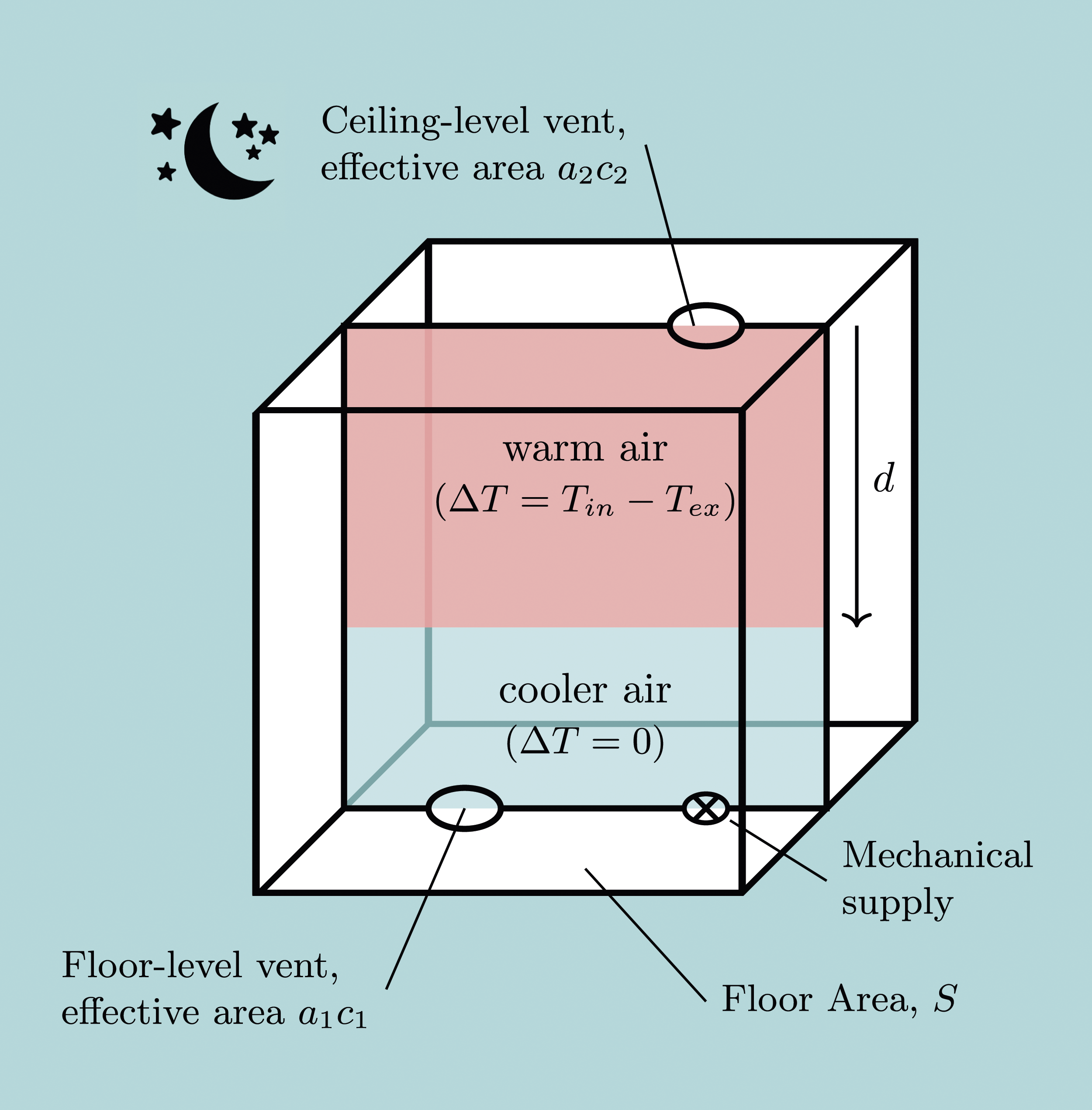

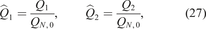
As the buoyancy driven pressure difference driving the flow is a function of the depth and buoyancy of the layer of warm air, we find that our selection of d and g′ as the key variables allows for a clearer understanding of the purge behaviour relative to that gained on selecting, say, h, H, T in and T ex . Indeed, it is worth noting that the room height, H, is not a key parameter in the theoretical description of a purge given that it serves only to limit the maximum depth that the warm air layer can initially take.
Consistent with the notation adopted by Connick & Hunt,
12
quantities relating to the vents are given the subscripts (⋅)1 for the floor-level vent and (⋅)2 for the ceiling-level vent, and those relating to the mechanical system are identified by the subscript (⋅)
F
which reads ‘forced’. Accordingly, a1 denotes the area of the floor-level vent and a2 the area of the corresponding ceiling-level vent. As is typical of the situation in practice, the areas of the vents in the floor and ceiling are considered to be small in comparison to the floor area, i.e. {a1, a2}≪ S. The instantaneous natural ventilation flow rates are denoted Q1(t) and Q2(t), and the mechanical, or ‘forced’, supply flow rate is denoted Q
F
. As anticipated in practice, the mechanical supply is maintained at a fixed rate. Figure 3 illustrates this notation and shows the directions of flow for the distinct flow regimes anticipated for the hybrid purge. Hybrid purging. A timeline with associated schematics of a typical hybrid purge showing a vertical section through the room modelled in §II at times t < t
rev
, t = t
rev
, and t > t
rev
, where t = 0 represents the instant the purge commences. For t < t
rev
, the direction of airflow through the vents is characteristic of the FF-regime. At t = t
rev
, the time of transition between the flow regimes, there is no airflow through the floor-level vent. For t > t
rev
, the direction of airflow is characteristic of the RF-regime. To track the progress of the purge, d(t) denotes the depth of the layer of warm air as a function of the time since the start of the purge.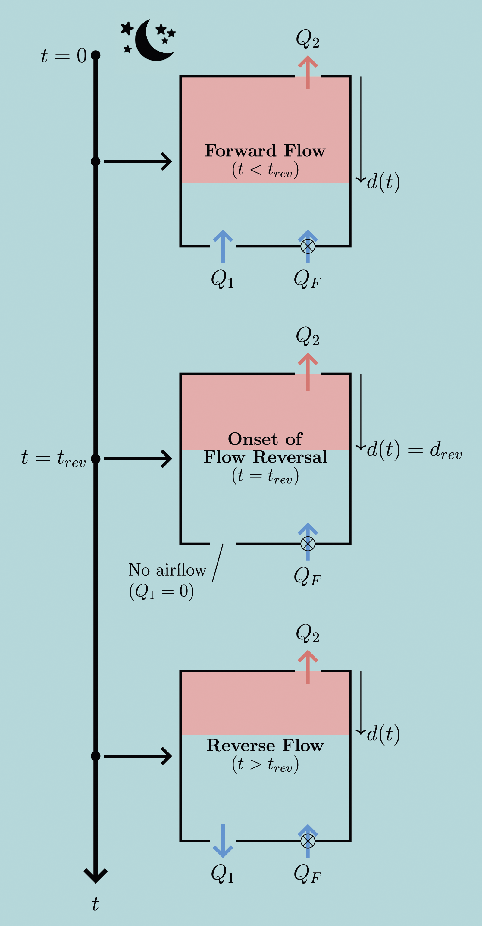
In line with previous first-order mathematical models that consider natural (e.g. Linden et al. 15 ) and hybrid ventilation (e.g. Connick and Hunt, 12 Hunt, Carroll and Waterson 13 ), we have opted to depict a box-shaped room and anticipate that it is these geometries that will be of primary interest to practitioners, particularly those considering ventilation strategies for modern buildings. However, our model is not restricted to box-like rooms because the primary constraint we impose is that the horizontal cross-sectional area of the room, S, does not vary with height – restrictions on how small this cross section can be are discussed in §II.B.1.
The purge is initiated by the simultaneous activation of the mechanical supply and the opening of the vents in the floor and ceiling. The inflow of cooler external air at low level displaces the warm air from the room via the vent in the ceiling. By assuming that there is no mixing between the upper layer of warm air and the cooler air entering through either the mechanical supply or the vent at floor level, and that there is unidirectional flow through the ceiling-level opening, it follows that a stable two-layer stratification is established (warm air above cool) and maintained as the purge progresses. The formation of a two-layer stratification is a standard assumption in models seeking to predict the purge time for natural displacement ventilation. 15 Hunt and Coffey 17 establish that the ratio of the inertial force to the gravitational force of the inflow at the height of the interface, expressed as the Froude number Fr i , must be less than 0.67 (Fr i < 0.67) for interfacial mixing to be avoided. It is assumed that the mechanical supply is fitted with an appropriate diffuser, if required, such that this Froude number criteria is satisfied. Wise & Hunt 23 show that bidirectional exchange flow occurs if the Froude number at the ceiling-level opening Fr2 falls below a critical value of Fr crit = 0.491c2 for a circular opening and Fr crit = 0.375c2 for a square opening. Thus, we restrict the applicability of our model to Fr i < 0.67 and Fr2 > Fr crit (see Appendix B for further details).
Buildings built to modern standards, or those that have recently been refurbished, will generally have high levels of insulation specified. For example, in the UK, Part L of the building regulations24,25 stipulates maximum U-values of 0.16, 0.26, and 0.18 Wm−2K−1 for roofs, walls and floors, respectively. Thus, we make the simplifying assumption that there is no heat exchange with the fabric of the room over the duration of the purge and thus the temperature of the air to be purged remains constant at temperature T in .
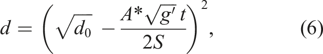
A. The limiting case of a natural ventilation purge
Although the existing literature does not address hybrid purging, the limiting case of a hybrid purge, namely, if the strength of the mechanical supply is reduced to zero can be assessed on examining a purge by natural displacement ventilation. 15
Given Q
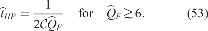
F
≡ 0 for a natural purge, with reference to Figure 3, Q1 = Q2 = Q
N
where Q
N
is the natural ventilation flow rate, the subscript N reading ‘natural’. It is readily shown that this flow rate is initially:


Based on the assumptions of no mixing (see Appendix B) and that displacement flow is maintained
2
, Linden et al.
15
predict that the variation in layer depth with time is:
B. Model development for a hybrid ventilation purge
B.1 Flow rates through the vents
In order to establish analytical predictions of the required purge time for a hybrid strategy, we must first derive relationships for the flow rates in the hybrid purge. Specifically, we need to quantify Q1(t) and Q2(t), for both the forward flow (FF) and reverse flow (RF) regimes, in terms of the mechanical supply flow rate Q
F
, the area of the vents, and the difference in air temperature between the room and the exterior, the latter represented by
For hydrostatic distributions of air pressure internally and externally (given that {a1, a2}≪ S, the vertical acceleration of the rising thermal interface is small in comparison to the acceleration due to gravity) the driving pressures across the vents at floor level (ΔP1) and ceiling level (ΔP2) are:
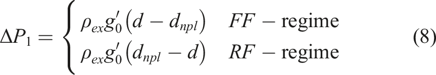
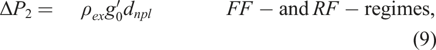
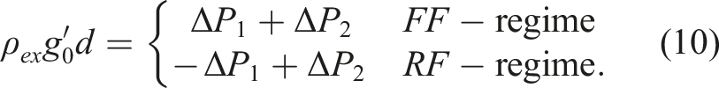
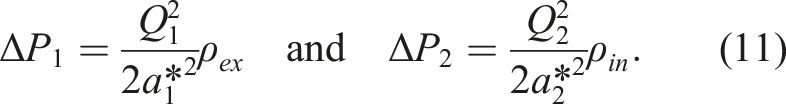
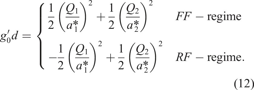


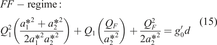
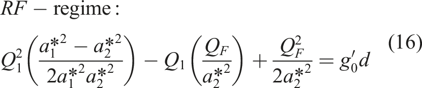
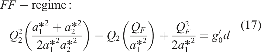
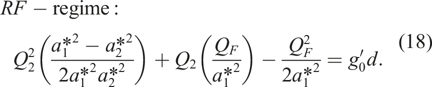
The expressions (15-18) govern the behaviour of the hybrid system, and they reveal how the instantaneous flow rates through the vents are related to the effective areas of the vents, the mechanical forcing, the buoyancy of the warm internal air, and the instantaneous depth of the layer of warm air.
Setting Q
F
= 0 in the equations for Q1 and Q2 in the FF-regime, (23) and (25), yields:
B.2 Non-dimensionalisation & governing parameters
Regarding the non-dimensionalisation of the governing equations and the initial conditions, d0 is the characteristic length scale and
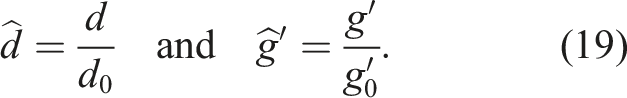

Scaling d as in (19), rather than using, for example
Defining:
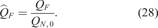
Scaling Q
F
using the initial natural ventilation flow rate QN,0 offers a straightforward and intuitive means of assessing the relative strengths of the mechanical and natural components of a hybrid purge system. For example, if
If there is no mechanical supply,
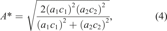
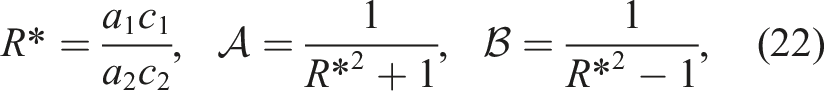
The parameter R* is introduced, (22), in line with the existing body of work on hybrid ventilation.12,13 This ratio of the effective opening areas in the floor and ceiling is typically in the region 0.5 < R* <2.0 for a room served by a natural ventilation system. 12
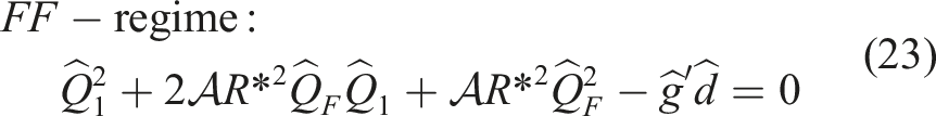
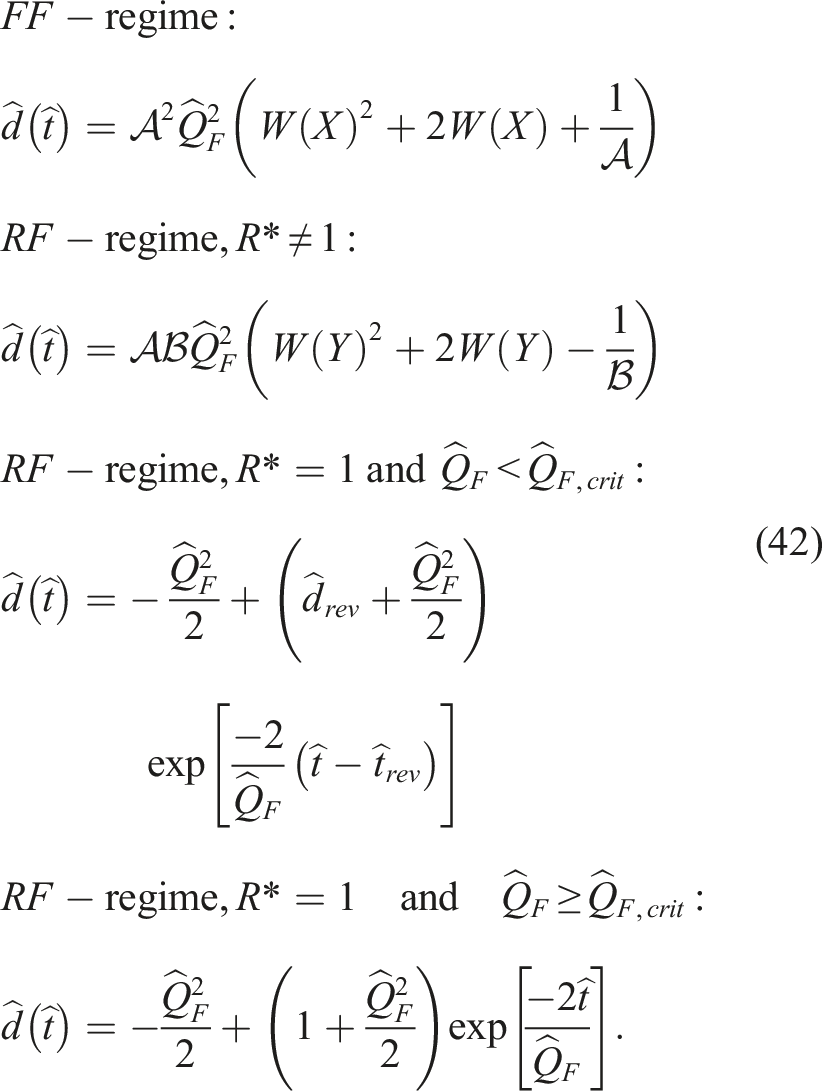
B.3 Solutions for forward flow
For the FF-regime, the solutions of (23) and (25) may be expressed as:
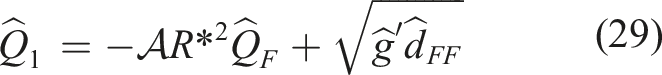
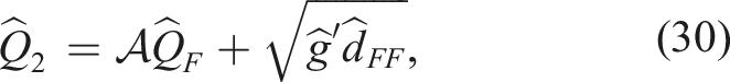
The second roots of the quadratics (23) and (25) are discarded given these yield non-physical predictions which do not match the natural case for
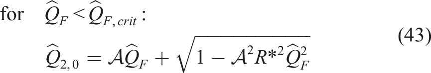
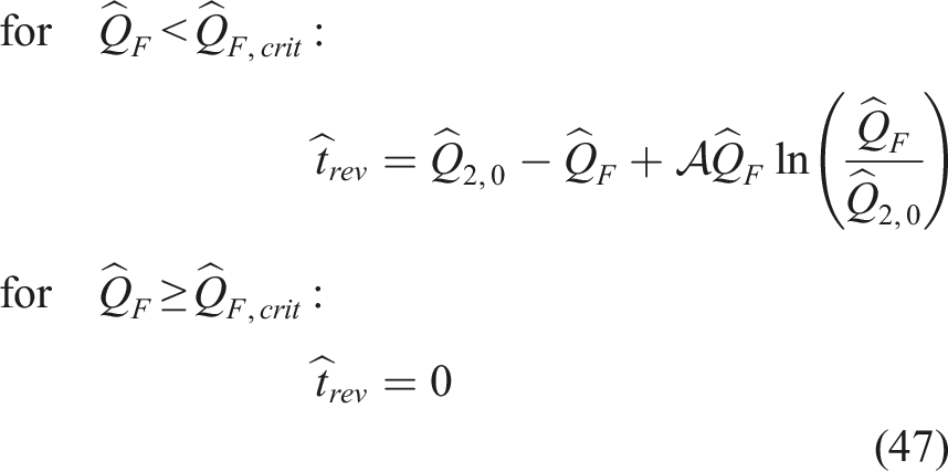
B.4 Onset of flow reversal
In physical terms, a reversal in the direction of flow through the floor-level vent (from inflow to outflow) occurs if the increase in internal pressure generated by the mechanical supply exceeds the buoyancy-induced pressure differences – for a purely natural purge, the latter drives an inflow through the floor-level vent. It is this reversal in the direction of flow through the floor-level vent which characterises the reverse flow regime. In this RF-regime, air enters the room only via the mechanical supply, i.e. there is no inflow through either vent (see Figure 3).
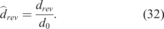
The depth of the layer of warm air at the instant t = t
rev
that the RF-regime commences is denoted d
rev
, where ‘rev’ reads ‘reversal’. In non-dimensional form:

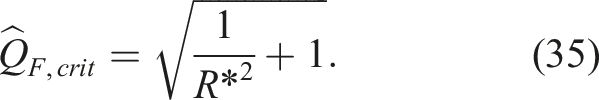
An expression for
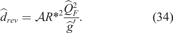
From (34), it is clear that increasing
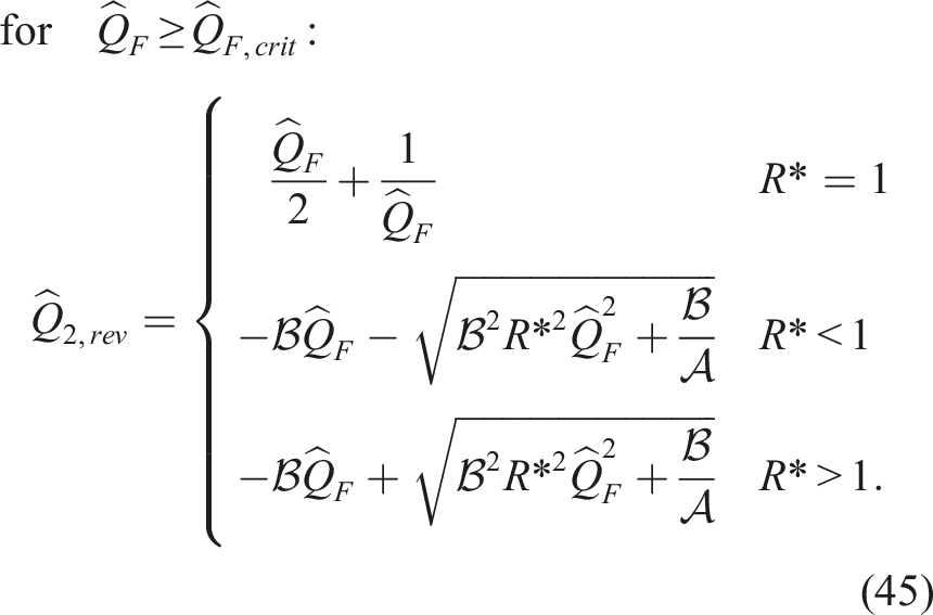
B.5 Solutions for reverse flow
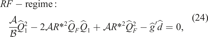
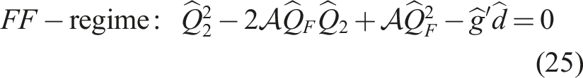
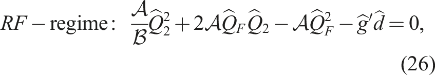
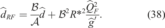
The solutions of (24) and (26) for the RF-regime are more complex than for the FF-regime, as they take a different form depending on the value of R* relative to unity. The solutions are:
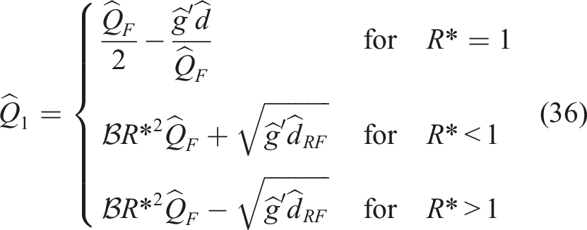
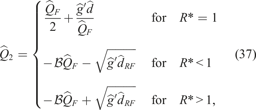
where
B.6 Rate of purging by hybrid ventilation
The rate at which warm air is purged from the room, and thus the time-varying depth of the layer of warm air, can now be established mathematically from the solutions to
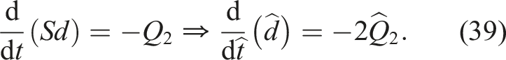
Defining:
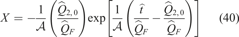
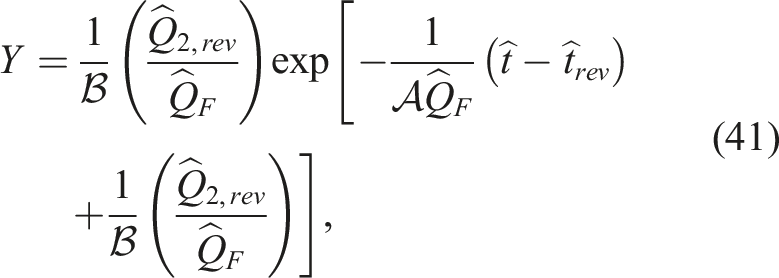

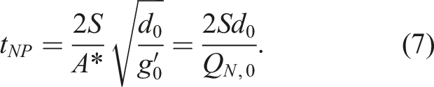
As we seek the hybrid purge time, (42) can be rearranged to instead give
where
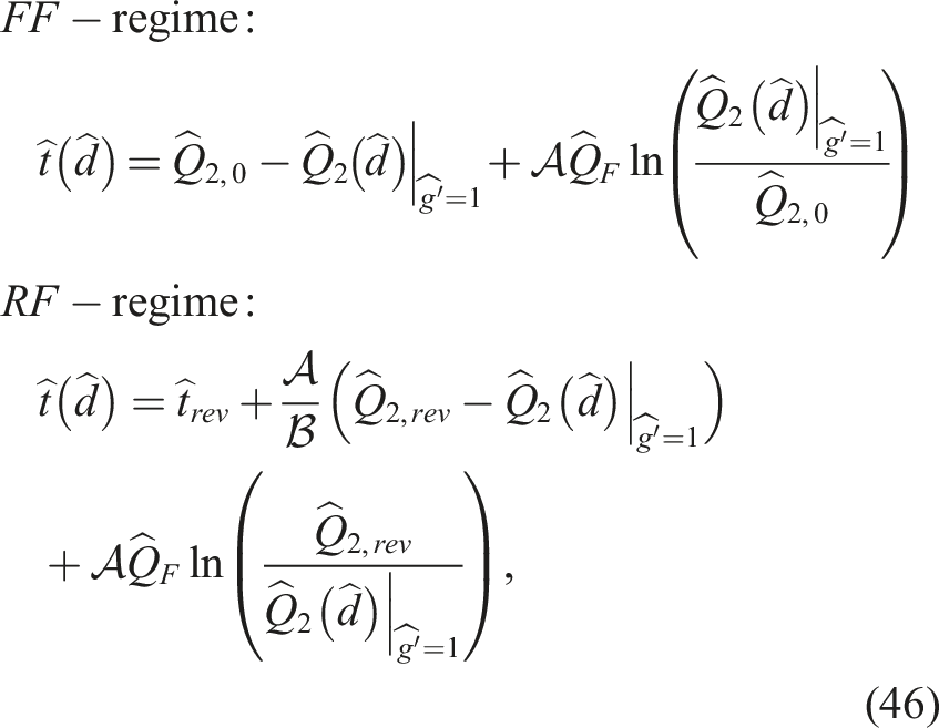
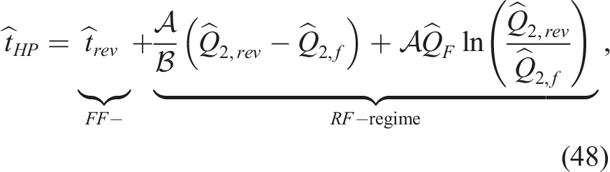
B.7 Time to complete a hybrid purge
The dimensionless time,

III. Laboratory experiments
In order to assess the accuracy with which our theoretical approach models a hybrid purge, complementary laboratory experiments were conducted for a wide range of R* and
Before commencing experiments on the hybrid purge, independent experiments were conducted (see Appendix A) to deduce the value of the discharge coefficient for the openings in the laboratory model of the room – this value being required to compare the theoretical predictions to the experimental results in §IV. Based on the data gathered, c1 = c2 = 0.669 ± 0.005. This value, lying between the accepted value of 0.61 for a sharp-edged opening 27 and 0.8 for a ‘short tube’, 30 was as anticipated given the aspect ratio of the opening.
A. Setup
Experiments were conducted at laboratory scale, with the setup depicted in Figure 4. The room being purged was represented by an acrylic box with a uniform rectangular cross-section (internal dimensions: 30.0 cm (height) × 30.0 cm (length) × 40.0 cm (width)) suspended within a larger acrylic visualisation tank representing the external environment (internal dimensions: 75.0 cm (height) × 100 cm (length) × 100 cm (width)). Using an established approach, dense saline solution and fresh water were used as the analogue of warm and cool air respectively. This choice is routinely used to investigate the purging of warm air from buildings, for example.15,20,26,31–33 The relatively large density differences which are possible between saline and fresh water allow for approximate dynamic similarity with the flows expected in the purging of rooms in buildings. The box was filled with a saline solution made by dissolving sodium chloride crystals in fresh water drawn from the same mains supply as the water that filled the visualisation tank. The densities of the freshwater and saltwater solutions were measured using an Anton Paar DMA 5000 M density meter, with the corresponding calculated values of g′ = g(ρ
saline
− ρ
fresh
)/ρ
fresh
being in the range: 5.40 ≤ g′ ≤ 29.2 ± 0.0585 cm s−2. Initial layer depths were in the range 17.9 ≤ d0 ≤ 25.9 ± 0.125 cm. Annotated sketch of the experimental setup – elevation view.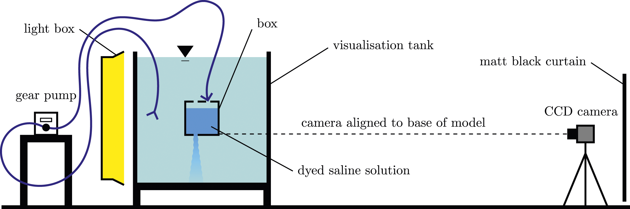
Because the (dense) saline solution was used in the laboratory experiments to represent the (buoyant) warm air, the experimental orientation is vertically inverted compared to that of a room filled with warm air. This inversion does not unduly alter the dynamics of the purge. In the experiments, the dense layer of saline solution was purged out of the base of the box, whereas in a room the buoyant layer of warm air is purged out of a vent in the ceiling. The Ismatec MCP-Z Process gear pump, which represented the mechanical supply, was connected to the top of the box and provided a mechanical supply rate of fresh water from the visualisation tank equivalent to
In order to replicate the vents in the floor and ceiling of the room, circular openings of diameter 3.00 cm and 5.00 cm were revealed as required in the top and base of the box through the removal of acrylic bungs. For a subset of the experiments, smaller circular openings of diameter 2.00 cm were used. The range of R* and A* values explored experimentally were: 0.500 ≤ R* ≤2.00 ± 0.0835 and 2.11 ≤ A* ≤5.95 ± 4.03 × 10⁻¹⁰ cm2.
For the purposes of tracking the density interface, the (relatively) dense saline solution was dyed using methylene blue dye. A light box, comprising an array of fluorescent tubes in an opal acrylic box, was used to blacklight the box with uniform diffuse lighting. The purge was recorded using a JAI SP-5000M-USB CCD (charge-coupled device) camera fitted with either a 35 mm or 75 mm fixed lens. The camera was aligned vertically with the base of the box in order to have a clear view of the interface, even as the purge was nearing completion. A frame rate of at least 3.125 frames per second was used to ensure that the behaviour around the instant of transition between the FF- and RF-regimes was captured. Image processing of the recorded experiments allowed the time-varying position of the density interface, and thereby the depth of the layer of dense fluid, to be established.
The direction of flow through the opening in the top of the box (equivalent to the floor-level vent in the room orientation) was monitored by tracking the motion of releases of neutrally buoyant dye injected (horizontally) into the opening. For experiments which commenced in the FF-regime, a change from an inflow to an outflow of dye indicated that there had been a transition to the RF-regime.
IV. Results and discussion
A. Flow reversal
Figure 5 plots the variation of Variation of the fractional warm air layer depth at the onset of flow reversal 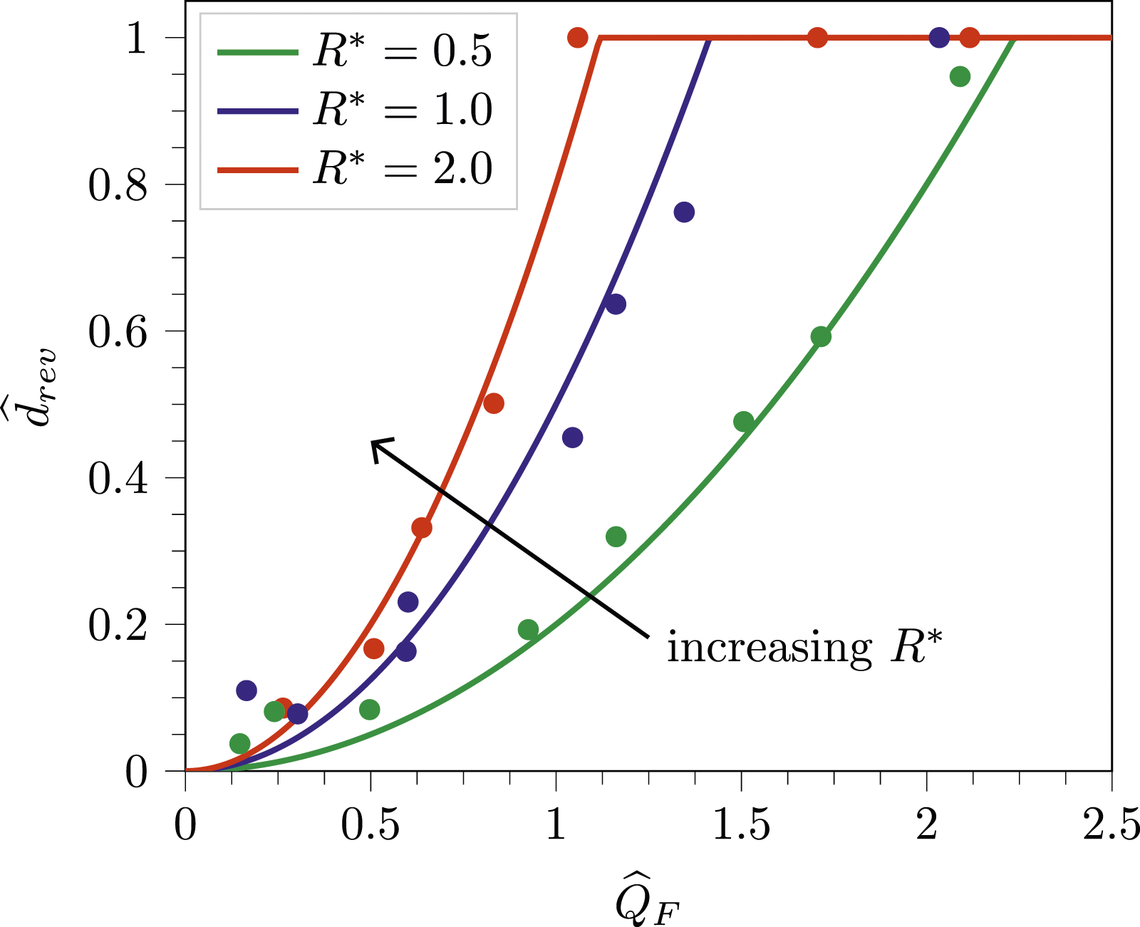
The implications of these results for the room ventilation scenario are that the depth of the layer of warm air at the onset of flow reversal increases as the strength of the mechanical forcing increases or as the area of the floor-level vent increases relative to the area of the ceiling-level vent. In other words, increasing
B. Rate of purging
The variation of the layer depth Variation in the warm air layer depth with time. (a) R* = 0.5, (b) R* = 1.0, (c) R* = 2.0. Left – theoretical predictions, centre – experimental results, right – combined theoretical predictions and experimental results. Analytical predictions for the FF- and RF-regimes from (46) are shown by solid lines and dashed lines respectively. The dashdot lines show the idealised natural purge from (6). The analytical predictions for flow reversal from (34) are shown by triangles, and the experimental results are shown by filled circles for the FF-regime and hollow circles for the RF-regime. Measurement errors in 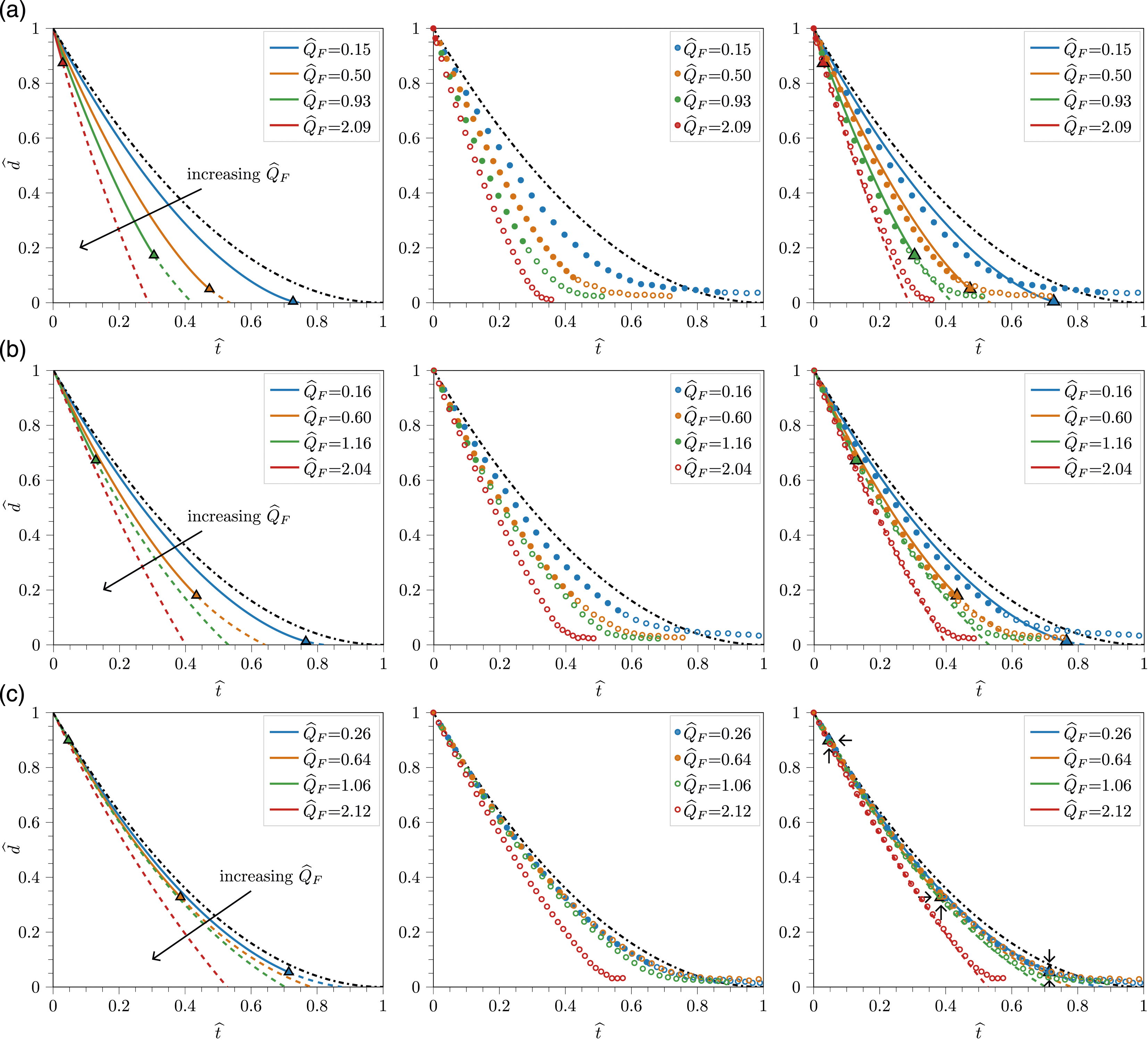
Qualitatively, the right column of Figure 6 highlights that there is generally very good agreement between the experimental measurements and theoretical predictions for the wide range of R* and
The results in Figure 6 have a number of practical implications for the hybrid purging of a room. Firstly, a hybrid purge can offer a significant improvement in purge time compared with a solely natural purge (for which
Figure 7 shows theoretical predictions of the warm air layer depth alongside images taken from a typical experiment at times Theoretical predictions superimposed onto images from one of the laboratory experiments at times 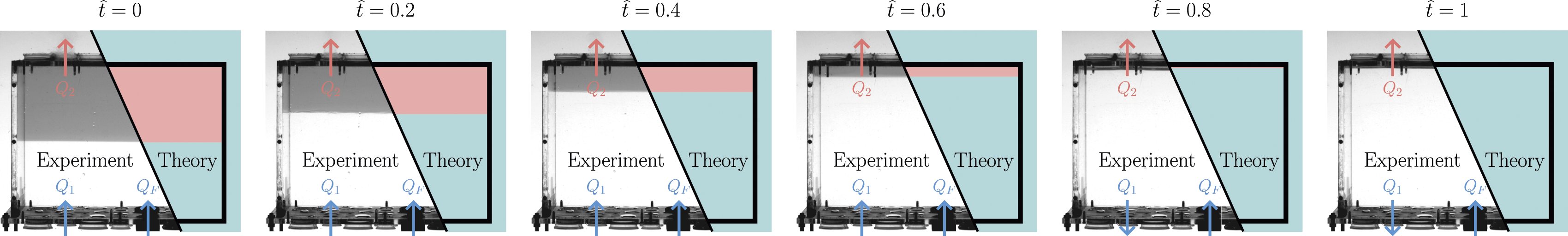
In order to highlight the differences between natural and hybrid purges, Figure 8 shows vertical sections through an example room at the following six ‘snapshots’ in time during the purge, Diagrams showing the theoretically derived layer depths and flow rates (the length of each arrow is proportional to the volume flow rate – a longer arrow indicating a higher flow rate) for four purges at six snapshots in time (left to right) to illustrate the role of R* at a fixed 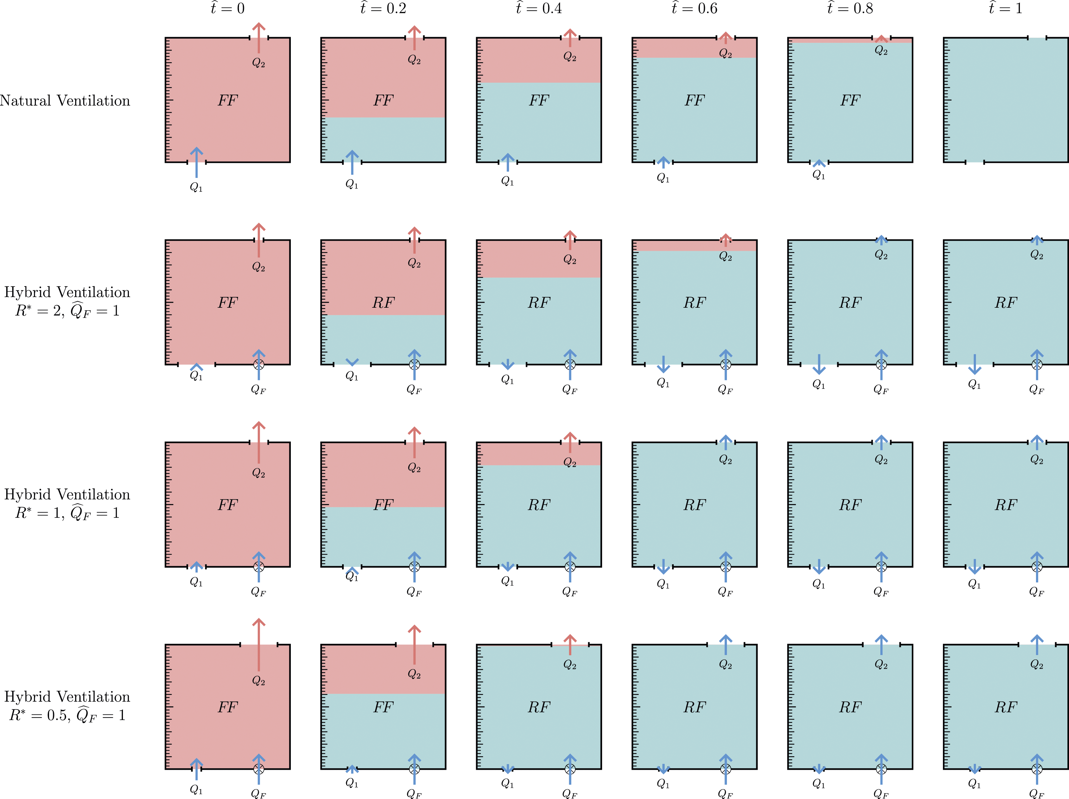
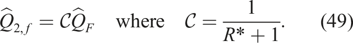
C. Time to complete a hybrid purge
In light of the draw down regime observed experimentally for shallow layer depths, Figure 9 plots the experimental results and theoretical predictions for the variation in the time taken to purge 90% of the initial layer depth Variation in the time to purge 90% of the layer of warm air from (46) with mechanical flow rate 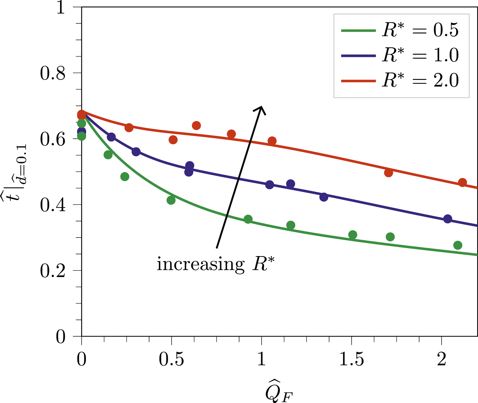
In practical terms, the addition of a floor-level mechanical supply to a room previously ventilated solely using natural displacement ventilation (i.e. using a hybrid strategy) can significantly reduce the time required to purge a given proportion of the layer of warm air, especially in a room with a low R* value (compare The variation in the hybrid purge time 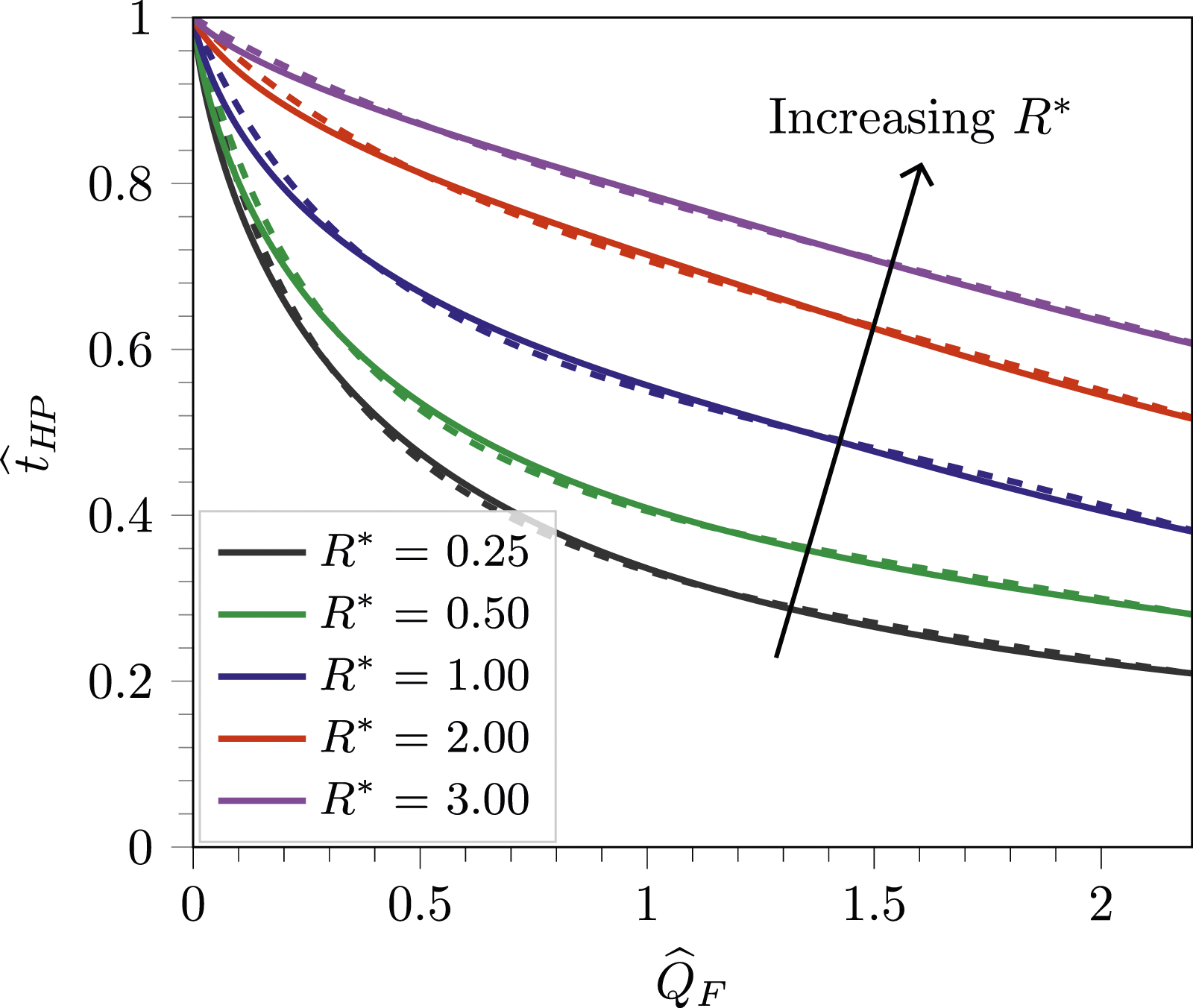
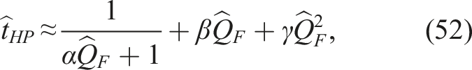
V. Approximating the hybrid purge time
With a view to improving the accessibility of our work, we now present an approximation for the hybrid purge time which avoids the use of logarithmic functions. This approximation shows good agreement with the full solution given in (48) for
A ‘curve-fitting’ analysis shows that the hybrid purge time can be approximated by:
In addition to the approximation above, we show in Appendix D that assuming the mechanical forcing dominates throughout the purge yields the upper bound estimate for the hybrid purge time:
VI. Example calculations
In order to acknowledge the wider applicability of our model for hybrid purging, the chosen example purge takes place when the room is unoccupied during the day, rather than at night. All calculated values are given to three significant figures, unless stated otherwise.
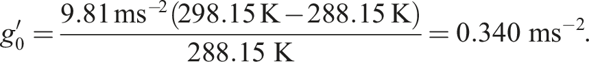
The scenario: Air at 25°C (=298.15 K) is to be purged from a modern well-insulated box-shaped lecture room with a floor area of S = 80 m2 and a floor-to-ceiling height of H = 4 m. The external air temperature is 15°C (=288.15 K). The room must be purged in the hour prior to the first lecture of the day and, on occasion, in the short break of circa 30 minutes between lectures, without relying on any wind assistance.
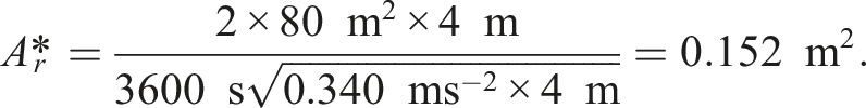
Solution procedure: As a starting point, we first seek a natural ventilation design that achieves the desired purge time of circa 60 minutes – this requires us simply to establish the required value
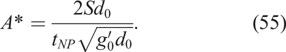
The natural solution: From (1), the initial reduced gravity of the warm air is:

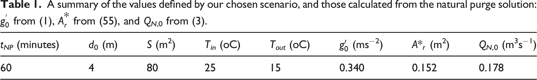
A summary of the inputs used to calculate the full and approximate hybrid purge times from (48) and (52).
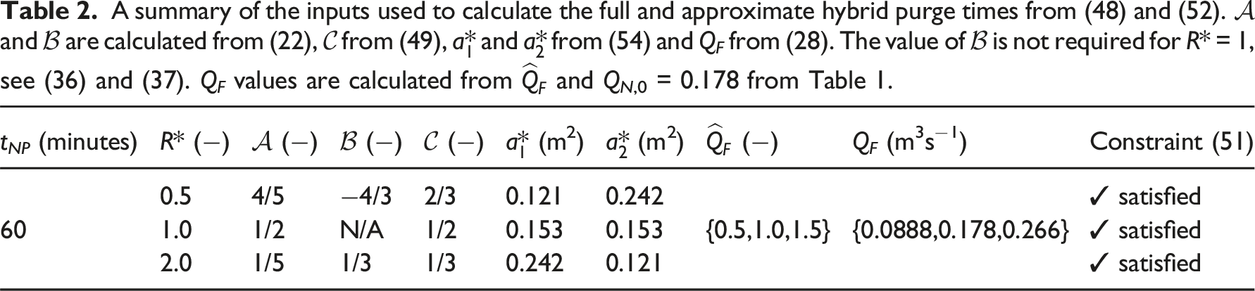
Full and approximate hybrid purge times, from (48) and (52), for R* = {0.5, 1.0, 2.0} and
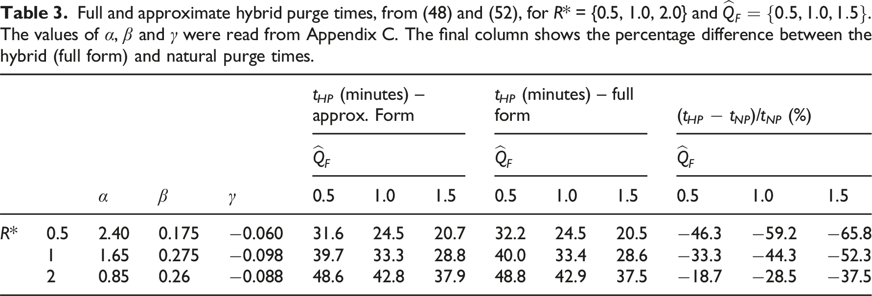
The hybrid approximation: To calculate our approximate solution for the hybrid purge time, the values of α, β and γ must first be read from Appendix C and then substituted into (52). For R* = 0.5: α ≈ 2.4; β ≈ 0.175; and γ ≈ − 0.06. Thus for 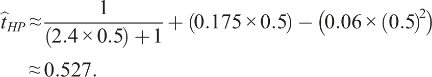

The full hybrid solution: To apply the full solution for the hybrid purge time (48), the values of 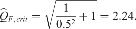
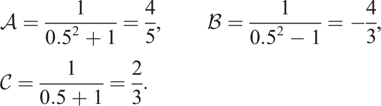
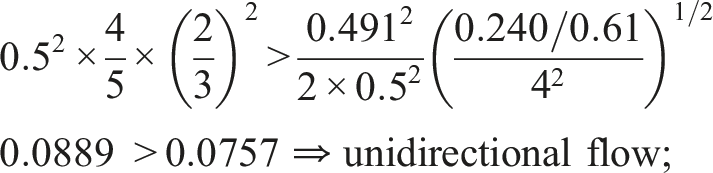
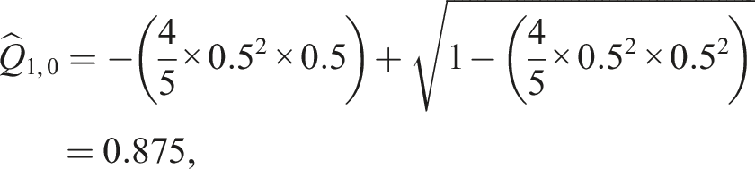
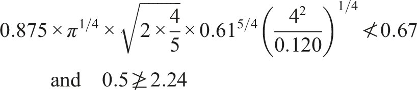
Given the purge commences in the FF-regime (as 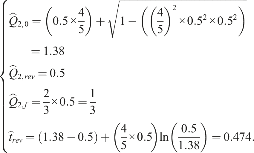
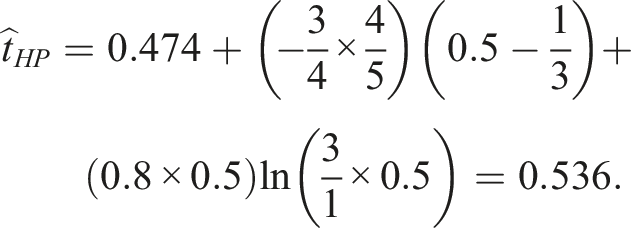

With a percentage difference of less than 2%, this example highlights the close agreement between the approximate and the full solutions, as well as highlighting that, with the addition of a modest mechanical supply flow rate of
After following the same calculation process for the other R* and (a) Bar chart comparing the natural purge time to the full and approximate hybrid purge times from (48) and (52). The bars show the full solution and the dashed lines the approximate purge time, the two are almost graphically indistinguishable. (b) Graphic showing, for 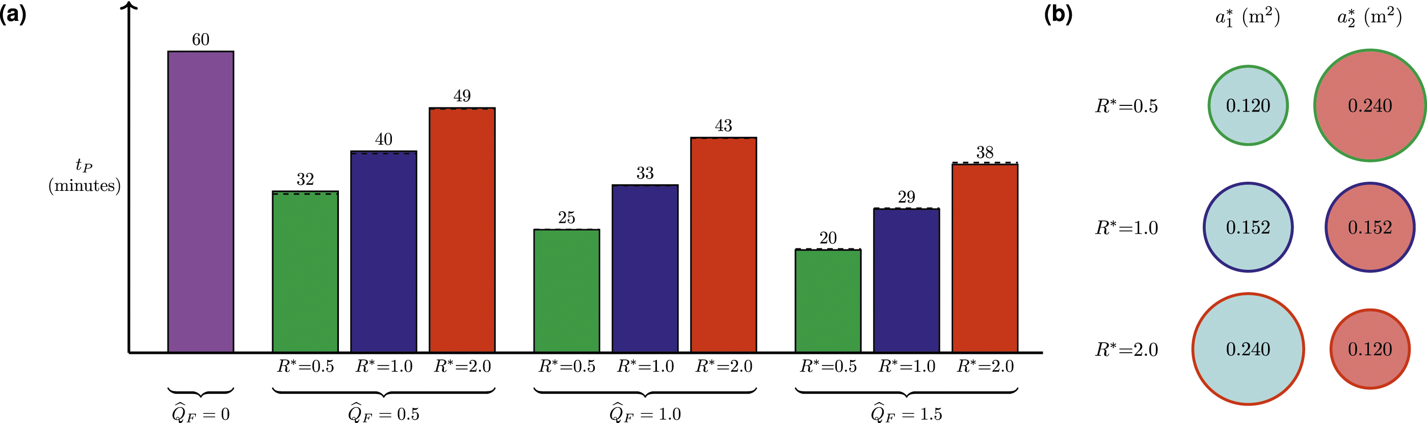
Using Figure 11(a) or Table 3, a hybrid purge time of under 30 minutes is achieved for:
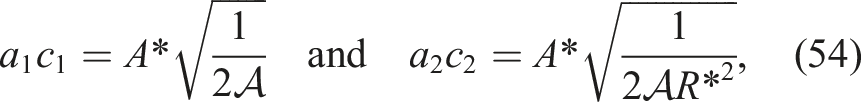
While the results in Figure 11(a) may suggest that an R* value lower than 0.5 would be preferable, note that Figure 11(b) highlights that the sum of the effective areas for R* = 0.5 and R* = 2.0 exceeds that for R* = 1. This increase in the sum of the vent areas becomes more pronounced as R* decreases further, for example, from (54), if R* = 0.5 then a1c1 + a2c2 = 0.360 m2, whereas if R* = 0.25 then a1c1 + a2c2 = 0.555 m2 – the latter a 53.7% increase from R* = 0.5 and an 82.2% increase from R* = 1. Thus for R* values further from unity, the sum of the effective vent areas must increase in order to ensure that
VII. Conclusions
Following within the simplifying framework of assumptions that underpin the current industry guidance on the calculation of natural ventilation flows, we have developed analytical solutions, supported by corresponding laboratory experiments, for predicting the transient flows associated with the purging of excess heat from a room using a hybrid ventilation strategy. The analytical solutions we derive, including for the time taken to complete a purge, offer practitioners the capability to expedite the first-order design of a hybrid system. Given the absence of any previous mathematical modelling on hybrid purge flows, we focused on an idealised scenario in which the building fabric was highly insulating and there was no reliance on wind to assist the purge. The hybrid strategy considered comprised the simultaneous use of a mechanical supply at floor level combined with stack-driven natural displacement ventilation via vents in the floor and ceiling.
A priori, one may have reasonably anticipated that a mathematical model for a hybrid purge would require no more than a straightforward extension to the theory that underpins a natural purge – and that there would be no change in the basic behaviour of the flow, other than for the rate of purging to increase. However, to the contrary, our work has shown that the behaviour is highly nuanced, the hybrid purge typically taking place across two distinct flow regimes with the time taken to complete the purge being the summation of the elapsed time in each. The rate of purging is indeed enhanced, with the ever-decreasing depth of the layer of warm air varying from a quadratic dependence in time for a natural purge, to a linear dependence for a mechanically-dominated hybrid purge.
Our approach reveals that the time to complete a purge depends on two ratios, (i) the strength of the mechanical supply relative to the natural stack-driven component
In our model, we restrict the vigour of the inflow in order to prevent interfacial mixing and restrict the area of the ceiling-level opening in order to prevent the onset of unbalanced exchange flows. These behaviours are the focus of ongoing research, and are likely to prolong a hybrid purge, as well as influencing the spatial distribution of internal heat during the purge.
Footnotes
Acknowledgments
GRH would like to extend his personal thanks to Prof. C. Middleton and the Laing O’Rourke Centre for Construction Engineering and Technology at the University of Cambridge. GRH is grateful for the financial support of Innovate UK (ref: 106163 Product Based Building Solutions – High Productivity Digital Integrated Assured DfMA for Lifecycle Performance) in collaboration with Laing O’Rourke.
Declaration of conflicting interests
The author(s) declared no potential conflicts of interest with respect to the research, authorship, and/or publication of this article.
Funding
The author(s) disclosed receipt of the following financial support for the research, authorship, and/or publication of this article: This work was supported by the Engineering and Physical Sciences Research Council (EP/T517847/1).