
Abstract
This study investigated the optimal design of a capillary heat exchanger device for the heat pump system and its innovative engineering application in a building. The overall aim was to use a capillary heat exchanger to obtain energy in coastal areas for promoting renewable energy in low-carbon building design. Initially, the main factors affecting the efficiency of the capillary heat exchanger were identified, a mathematical model was then established to analyse the heat transfer process. The analysis showed the flow rate and the capillary length are the key factors affecting the efficiency of the capillary heat exchanger. Secondly, to optimize the structural design of the capillary heat exchanger, the heat energy transfer is calculated with different lengths of the capillary under various flow rates in summer and winter conditions, respectively. Thirdly, a typical building is selected to analyse the application of the capillary heat exchanger for extracting energy in the coastal area. The results show the performance of the selected capillary heat exchanger heat pump system, in winter, the heat energy transfer rate is 60 W/m2 when the seawater temperature is 3.7 °C; in summer, the heat energy transfer rate is 150 W/m2 when the seawater temperature is 24.6 °C. Finally, the above field test results were examined using a numerical simulation model, the test and simulation results agree with each other quite well. This paper is conducive in promoting the development of the capillary heat exchanger heat pump as an innovative sustainable technology for net-zero energy and low carbon buildings using renewable energy in coastal areas.
Introduction
Previous studies have focused on exploiting renewable energy for reducing energy consumption.1,2 Heat pump technology has been identified as a key technology in low carbon-building design and is widely used as a heating and cooling system in buildings. 3 There are many countries such as China, America and the UK that has rich shallow geothermal energy in coastal areas. 4 Heat pump technology can often be effectively used with seawater to extract renewable energy for buildings to achieve a net-zero target. Compared with the traditional energy extraction methods, heat pumps have the following beneficial features; large heat capacity, high heat exchange coefficient and little damage to the seabed in coastal areas. 5 Therefore, the heat pump has considerable potential for application in renewable energy extraction in coastal areas.
For many years, the application of heat pump technology to achieve low carbon design of buildings has attracted wide attention. The are several burial forms of heat exchanger pipes of the traditional ground source heat pump systems, such as the horizontal, vertical and coiled types. 6 Many scholars have studied the different laying forms of the ground source heat exchanger. Kupiec (2015) developed a mathematical model of a horizontal tube underground heat exchanger, which was based on a one-dimensional equation of transient heat conduction. 7 Fan (2007) investigated the configuration of a vertical dual-function ground heat exchanger, which was used in a ground-source heat pump system with an integral soil cold storage. 8 However, there are some deficiencies in the previous forms of the ground heat exchanger system. If the heat exchanger is laid horizontally, it needs a large underground area and has an unstable operational performance. If the heat exchanger is laid vertically, the capital cost is high due to the expensive excavation work required for digging deep trenches or boreholes. If the heat exchanger is laid in a coil, due to the overlap between the pipes, a short circuit might occur. Compared with traditional exchanger systems of ground source heat pumps, in this study, a capillary heat exchanger was buried in the shallows under the seawater as the energy extraction device, which is heated and cooled by the medium in the capillary. According to the actual conditions in coastal areas, capillaries can be assembled both horizontally and vertically, which forms a three-dimensional heat exchange network. Compared with traditional heat pump technology, the capillary heat exchanger is more competitive because it has a number of advantages, for example, large heat exchange areas, small resistance and uniform heat exchange process. 9 The main aim of this paper is to investigate and evaluate the optimum design and the application of capillary heat exchanger heat pump in buildings and to promote capillary heat exchanger heat pump systems as a key technology in the low carbon-building development.
Previous researchers have studied the capillary heat exchanger as air conditioning terminal radiation systems. Lazarus (2015) proposed placing a capillary tube heat exchanger underground a 120 m2 greenhouse to keep the room at 12 °C during the night. 10 The capillary system was used as ground thermal storage in the greenhouse. Attar et al (2013) conducted numerical calculations using the simulation tool Transient System Simulation (TRNSYS 16) to optimise the capillary heat exchanger length and water flow velocity. This resulted in reduced energy costs of 25% in December in the heating condition and by 51.08% in April in the cooling condition when the capillary heat exchanger was adopted in the greenhouse. 11 Hazami et al (2017) used water as a cooling source and extracted energy at 30 m below ground level with a capillary heat exchanger. 12 It was concluded that the thermal efficiency was approximately 80% in the Tunisia Salammbo museum and aquarium. Hazami et al (2017) proposed the devices using a local daily solar energy storage system. 13 Approximately 30% to 49.5% of the daily energy was stored in the heat storage unit. These previous studies indicated that capillary heat exchangers are critical in the utilisation of renewable energy with heat pump systems to extract energy. At present, theoretical research into the capillary heat exchangers is more mature. Currently, the research on the capillary tube is mainly limited to the capillary radiation heat exchanger systems. Also, there are few pieces of literature about capillary heat exchangers used as a front-end heat exchanger in ground source heat pump systems in coastal areas. Consequently, little attention has been paid to the optimum design and application of the capillary heat exchangers in coastal areas. In addition, few studies are comparing theoretically calculated values and field test data on the performance of a capillary heat exchanger in a typical building. The optimal design of capillary heat exchangers is critical to improve the energy efficiency of buildings and promote the development of low-carbon buildings. Therefore, how to design the front-end heat exchange system, which can adapt to various water areas with high heat transfer efficiency and low cost becomes an important challenge to solve the front-end heat transfer of surface water.
Capillary technology presents a new method in the field of Heating Ventilation and Air-conditioning (HVAC). Due to the low water temperature required for heating, the energy consumption during the transmission process and distribution can be greatly reduced. The matching heat pump system can further improve the Coefficient of Performance (COP) value of the heat pump unit, and the energy-saving effect is remarkable. The hot and cold water flows in capillary tubes with an outer diameter of 4.3 mm, an inner diameter of 2.8 mm, which can quickly extract heat or cooling capacity from the seabed to rapidly meet the requirements of heating or cooling. Due to the large heat exchanger area, a large amount of cold or heat is extracted from the seabed, which reduces the temperature difference between the heat exchanger surface and the seabed around the coast. The unique parallel structure of the capillary network greatly reduces the resistance of the pipeline. The outer diameter of the capillary tube is 4.3 mm, the space occupied by a pipe is small, the water flow of the single pipe is small, and the safety is high. The whole capillary heat exchanger system can compress or absorb more heat compared with the conventional system, which makes the system save energy significantly, and the energy consumption is less than 50% of the conventional system.
In this research, the capillary heat exchanger is buried in the coastal shallows. Capillary polypropylene plaits are taken as an underground energy extraction device and its optimal selection method and rationale are studied. In coastal areas, the seawater temperature has a big influence on the capillary heat transfer. Thus, it is important to understand the thermal and fluctuation heat exchange behaviours between seawater and seabed. The objective of this research focuses on three aspects of the capillary heat exchanger, including the optimum design method, reasonable utilisation and comparison on simulation results and field test data. First, based on the minimum principle of entropy theory, the optimum structure is designed for the capillary heat exchanger. Second, the feasible utilisation and heat transfer effect analysis are carried out for the capillary heat exchanger in coastal areas based on case studies. Finally, a comparison between the results of the numerical simulation and the previous experimental field tests is made.
Methodology
To use capillary heat exchanger heat pumps to reduce the energy consumption of buildings and promote low carbon building design, it is necessary to optimise the structural design of the capillary heat exchanger device and its engineering application in building. First, an investigation of the overall background of the capillary heat exchanger heat pump system is required. Then, the related heat transfer theory of capillary heat transfer is described.
Three steps have been taken to achieve this aim. The first step is to optimise the structure of the capillary heat exchanger according to the basic principles of heat transfer. The second step is to select a typical building to analyse the heat transfer of the capillary heat exchanger in both winter and summer. The third step is to compare the data calculated by the numerical simulation with field test data. The detailed methods of the three steps are described in the following sections.
Capillary heat exchanger system
The heat exchanger is composed of capillary tubes with 4.3 mm external diameter (do) and 2.8 mm inside diameter (di), and the wall (Am) is 0.75 mm thick. The spacing between plastic capillary tubes is 20 mm, as shown in Figure 1. 14 The heat transfer medium in the polyethylene of raised temperature resistance (PERT) materials capillary heat exchanger is the aqueous solution of 12.5% ethylene glycol fluid. The heat transfer per unit area is the heat transfer per single mat capillary heat exchanger per square metre.
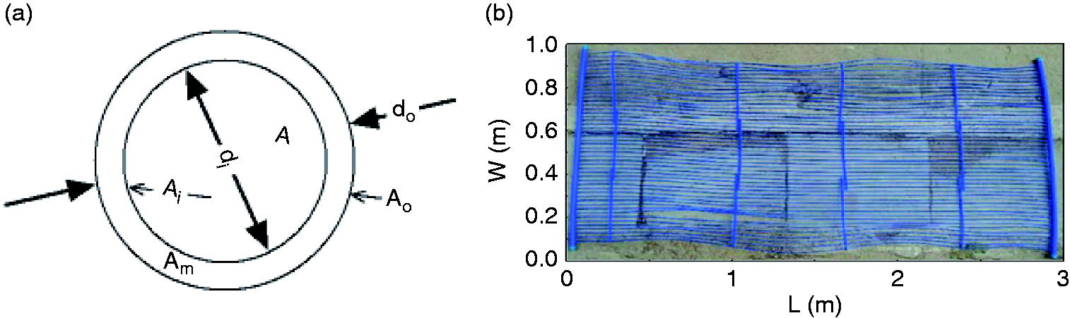
The capillary heat exchanger. (a) Cross-section of a capillary tube and (b) photo of a single mat capillary heat exchanger.
Since the capillary heat exchanger is placed undersea in coastal areas, the heat capacity of the seabed is approximately infinite. The heat pump systems consist of the capillary heat exchanger, ethylene glycol solution flow circulation, heat pump units and room terminal. The heat pump system schematic drawing is shown in Figure 2. The heat pump unit consists of the evaporator, conversion valve, throttle device, compressor and condenser. The heat transfer process of the capillary heat exchanger is described as follows. First, the capillary heat exchanger extracts heat from the seabed. Then, heat or cooling energy is transferred to the indoor heat exchanger with the heat pump unit. Finally, the indoor heat exchanger heats or cools the indoor air in the room as the air-conditioning system. 15
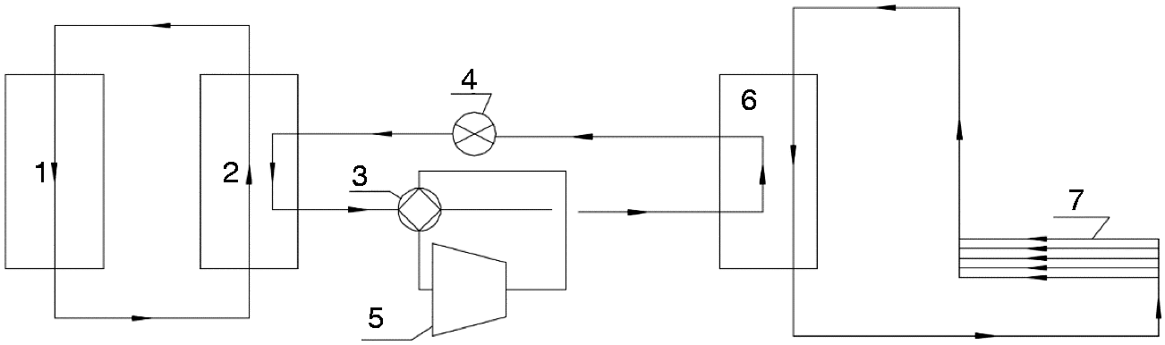
Diagram of the heat pump system with capillary heat exchanger. 1. Indoor heat exchanger, 2. Evaporator, 3. conversion valve, 4. Throttle device, 5. Compressor, 6. Condenser, 7. Capillary heat exchanger.
The capillary heat exchanger has advantages: it can be applied under high temperature, high-pressure and corrosion resistance. It can be designed with a thin tube wall for a large heat exchange area to achieve high heat exchange efficiency. Also, this new type of heat exchanger has the advantages of utilizing low-quality water. The buried part of the capillary heat exchanger in the coastal areas is mainly in the sandy under the shallow water near the coast. The capillary heat exchanger heat pump system in coastal areas, which uses renewable ocean heat and seabed heat coupled with the characteristics of ground source heat pump system and seawater source heat pump system, is also affected by the periodic change of ocean tide. Such a heat pump system with this front-end capillary heat exchanger is different from other types of the heat pump system, the study of the performance of this new type of heat pump system is important.
Compared with the open seawater source heat pump system, the benefit of a capillary heat exchanger heat pump system in coastal areas is avoided the corrosion to the heat pump unit and pipework by seawater. It does not need to add auxiliary equipment such as filtration and water treatment and does not need to use a high-cost Titanium alloy anti-corrosion heat exchanger, therefore can greatly reduce the project investment and operation cost; it can also address the issue of fixing the front-end heat exchanger of closed seawater source heat pump system, and the capillary heat exchanger will not have the problems of heat flow short-circuit and easy scaling of a spiral coil heat exchanger. The system has great significance in engineering application. The capillary heat pump system provides a new engineering solution for heating and cooling by utilising renewable seawater heat and seabed heat. The operation characteristics of a capillary heat pump system in coastal areas are obtained in this study, which can give guidance for the large-scale heat pump system using the capillary as the front-end heat exchanger and provide corresponding theoretical and technical support.
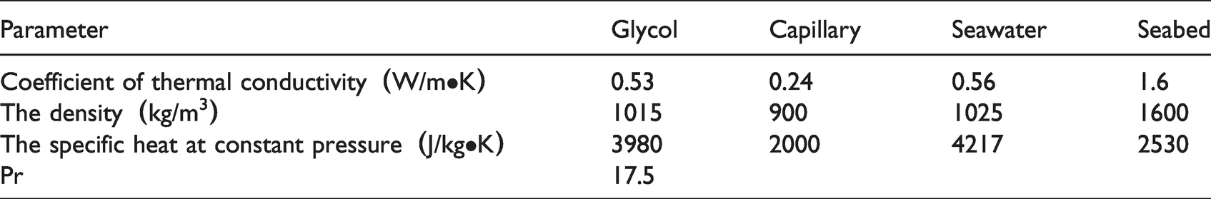
The relative physical parameters are defined for the design of the capillary heat exchanger in the coastal areas shown in Table 1. The average design temperature of seawater is 3.7 °C in winter and 24.6 °C in summer. 16 Seabed temperature at a depth of -10 m is maintained constantly at 13.8 °C annually. 17
Capillary heat exchanger system parameters.
Heat transfer theory
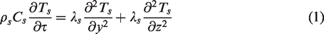
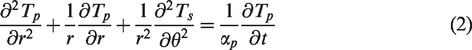
The heat transfer process of the capillary heat exchanger is analysed. Heat transfer equations of the sandstone layer around the capillaries are given in equations (1) to (8).18–20
Heat transfer equation of the seabed around the capillary:
Heat conduction equation of capillary wall:
Fluid heat transfer equation in a capillary tube is given:

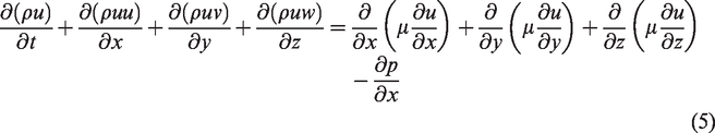
For a microelement at any position in the capillary, mass conservation equation:

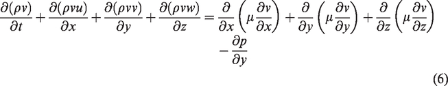
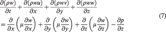
Conservation of momentum equation:
Energy conservation equation:

The heat transfer design mathematic model is composed of equations (1) to (8) equations for the capillary heat exchanger, which has typical characteristics of fluid-solid coupling heat transfer. These 8 heat transfer equations need to be combined to calculate the temperature distribution of the heat exchanger. The outlet temperature of the heat transfer medium in the capillary is calculated using the computational fluid dynamics (CFD) software.
According to the heat transfer theory, heat energy exchange base on the heat transfer medium in the capillary heat exchanger, heat energy 
The formula for the performance coefficient of seawater source heat pump units is given as equation (10).
24

Methodology
Capillary optimal design method
According to the above capillary heat transfer design mathematic model, the length of the capillary heat exchanger is determined by the total energy load of the building and the maximum outlet temperature of the capillary. The following steps can be followed to determine the total length of the capillary:
The building hourly energy load is calculated based on the detailed design of the building. Then, the heat pump unit is selected. The energy load Q of the capillary heat exchanger is determined by the heat pump unit. The capillary heat exchanger length and its wall surface temperature are calculated based the above Q, the operation time, the seabed thermal property parameter, and the given initial setting of the capillary heat exchanger. The local water temperature is checked. The summer and winter heat transfer temperatures are determined by the local seawater temperature. With the rate of heat transfer assumed to be constant, the inlet temperature of the capillary heat exchanger could be obtained. According to the type of capillary heat exchanger, the difference capillary length and the heat transfer temperature are calculated based on the unit-cooling load and heat load of the heat exchanger. To obtain the total cooling and heat load of the capillary heat exchanger, the maximum length of the capillary heat exchanger is calculated under the total cooling and heating load of the building. Finally, the total amount of circulation flow of the capillary heat exchanger is calculated, and the number of capillary circuits required in parallel is determined.
The heat energy transfer for the capillary heat exchanger buried in the coastal shallows is calculated considering the heat exchanger efficiency as well as the inlet and outlet temperature of fluids in the capillary. When the type of capillary is given, the efficiency of the capillary heat exchanger is reckoned. The higher and lower temperature of the inlet and outlet medium fluids is given as constant parameters. The suitable numbers of heat transfer units are selected for the heat exchanger in the process of the calculation method. 23
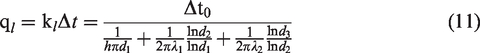
By using the theory of steady-state heat transfer, the heat energy transfer (q
l
) between the fluid in a unit length capillary heat exchanger and the seabed is given by equation (11).
25
The heat exchange load of the unit area of a capillary heat exchanger is 
When The heat energy transfer of capillary heat exchanger and the temperature difference in the capillary is fitted, based on numerical simulations, the results for p are p1= −0.03; p2 = 0.69; p3 = 5.67; p4 = 55.49; p5 = 0.18. Therefore, the Q for the unit area of the capillary heat exchanger is calculated from equation (13).

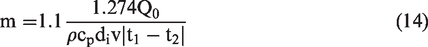
The total number of capillaries (m) required is calculated using equation (14).
Entropy production (Ns) is a measurement parameter for energy dissipation, which reflects operational effectiveness. The minimum entropy theory has been extensively studied in the flow and heat transfer of irreversible concentrating. 26 Theoretically, the distribution of the available energy loss is obtained by calculating the total entropy production of the system. If the total entropy production of the system is minimised, the energy consumption is minimized, and heat transfer optimized. 22
Aiming at the convective heat transfer process that is prevalent in the thermodynamic cycle, the minimum entropy production theory and heat transfer capacity evaluation system are proposed. The thermodynamic optimisation of total entropy production is caused by viscous dissipation produced by entropy.
27
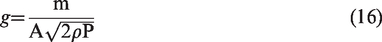
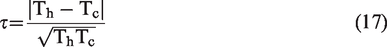
Minimum entropy production for capillary exchanger is calculated in the coastal areas. The entropy production is shown in equations (15) and (16).


In equations (18) and (19), when the fluid is heated, constant factor n = 0.4; when the fluid is cooled, n = 0.3. 

In the design method of the capillary heat exchanger, the temperature difference method and the effective heat transfer unit number method are adopted.
5
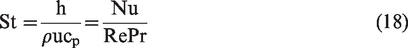
The effective heat transfer unit method is used to evaluate the performance of the capillary heat exchanger. The heat exchanger efficiency, ε, is defined as the ratio between the actual heat transfer capacity and the maximum heat transfer capacity. ε is shown in equations (22) and (23). The number of the heat transfer unit (NTU) represents the amount of heat transfer capacity as equation (24). When the capillary heat exchanger efficiency increases, the heat transfer performance is better.
12


From the above mathematical evaluation for the capillary heat exchanger placed undersea, internal flow velocity and capillary length are identified as the main factors influencing the efficiency of heat exchange. The
Flow chart of the calculation process.
Capillary application method
To assure both the heating load in winter and cooling load in summer, it is necessary to calculate the heat energy transfer of the capillary heat exchanger in winter and summer. Then, a suitable number of capillary tubes that meet the requirements of both winter and summer can be selected to make sure the capillary heat exchanger can accommodate the whole year.
After the optimum design of the capillary heat exchanger is applied, the heat transfer per unit area is calculated, the total heat energy transfer by capillary is obtained when the seawater temperature is 3.7 °C in winter and 24.6 °C in summer. Finally, the total number of capillaries and the number of grids is calculated in both winter and summer.
Comparison method
It is necessary to conduct a comparative analysis and verification of the capillary heat exchanger design method. To place a given structure of capillary heat exchanger at the coastal area in Qingdao P.R. China, the heat transfer performance was tested by an on-site experiment using the capillary design method. According to the methods described in the previous study, Zhou (2016) selected the capillary heat exchanger of a certain structural type and made tests in the field. The verification is based on the measured experimental data. 16 The capillary heat exchanger is shown in Figure 4, which is buried in the coastal shallows.
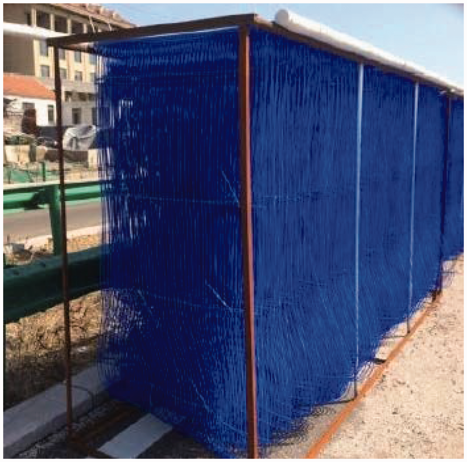
The capillary heat exchanger buried in the coastal area.
The field testing of capillary heat exchanger heat pump with horizontal pipes were buried in the coastal shallows. The piles were buried 5.0 m in depth and 50.0 m far away from the coast. The flow rate was 10.4 m3/h. The condenser inlet average temperature was 35.4 °C and the outlet average temperature was 40.6 °C in the field testing period from 2nd April to 18th April 2017. The evaporator inlet average temperature was 11.0 °C and the outlet average temperature was 6.5 °C during the test period from 4th of July to 12th of August 2017 for cooling. (See appendix 1)
Results and discussion
Optimisation of capillary design
The optimised design of the capillary heat exchanger is of significance for energy reduction and promotion of low carbon application in buildings. This section describes the calculation results of the optimal design for the capillary heat exchanger. Figure 5 shows the
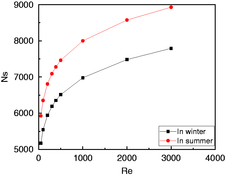
Ns distribution vs. Reynolds number.
According to the calculated results, the relationship between the capillary heat exchanger energy load Q, the inlet and outlet temperature difference
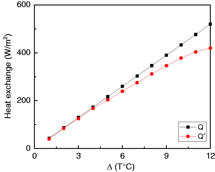
Comparison of the formula of heat transfer per unit area.
Application analysis for capillary heat exchange in the coastal area
To demonstrate that capillary heat exchanger technology can be utilised in low carbon building design, a typical building is chosen for the field test. A typical building with 100 m2 floor area in Qingdao was selected as the pilot test building. The building heat transfer rate was 60 W/m2 in winter and 150 W/m2 in summer, according to previous records. 16 , 17 The total cooling load was 15 KW in summer, and the total winter heat load was 6 KW. The heat transfer capacity per unit length tube of the horizontally buried geothermal heat exchanger was 50 W/m2 in summer and 30 W/m2 in winter. The total length of the buried caterpillar tube required was calculated to be 300 m. The horizontal spacing of each buried tube was 1.5 m, and the total underground area was 300 m2.
If the capillary flow rate is 0.1 m/s, each capillary mat length is selected as 3 m for both winter and summer based on the common engineering application. A close circuit capillary heat exchange system for a building is recommended. In winter, the minimum temperature is 3.7 °C for seawater. Considering the operational safety of the capillary heat exchanger, the recommended difference between the capillary inlet and outlet temperatures is approximately 2 °C, and the outlet temperature is 1 °C. The capillary inlet and outlet temperature difference is 1.43 °C in winter. The Winter unit area heat transfer rate is 59.3 W/m2. In summer, the seawater temperature is 24.6 °C. The capillary inlet and outlet temperature difference is 3.2 °C in summer. Also, the total amount of heat transfer is 132.7 W/m2.
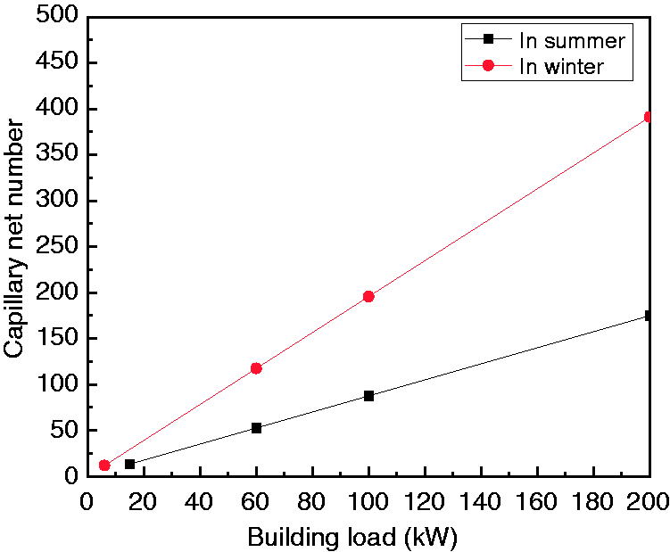
As shown in Figure 7, the number of capillaries varies with the different medium flow velocity inside the capillary. If the flow velocity is 0.1 m/s in the capillary, the corresponding numbers of the capillary grid are 1690 in the summer and 1888 in winter.
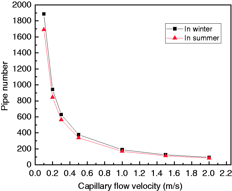
The number of capillary tubes required.
As shown in Figure 8, it is confirmed that the numbers of capillary mat are 10 to satisfy the total building load. Each capillary mat is 3 m long and 1.0 m wide (Figure 1). There are 50 capillaries with an interval of 0.02 m along the width direction, and the heat exchange area is 3 m2.
The numbers of the capillary mat.
Comparison between calculation and field test
A typical building is selected for testing and the numbers of capillary layers are calculated. The building maximum heat load is 60 KW in summer, and the building maximum cooling load is 53 KW in winter. The area of the capillary tube is 204 m2. The actual laying area of the capillary is 244.8 m2. The actual laying of the capillary has a coefficient of 1.2, which is to ensure the building gets enough energy. The area of each capillary mat is 4 m2. The number of capillary layers is 61.
The average building monthly load is shown in Figure 9. The highest heat load appears in January, while the highest cooling load is in August. The test periods during the last 4 days in the heating season and the start of the transition season of Qingdao on the 2nd of April 2017, the outdoor temperature ranged from 11 °C to 16 °C. The seawater temperature was 3.9 °C on 2nd April and 10 °C on 18th April, the sea was at a distance of 50 m from the selected hotel building, and during the test period, the average indoor temperature was 22.4 °C and the seawater temperature was 14 °C. The COP was 4.06 in the seawater source heat pump unit. The COP was 3.17 in the whole capillary heat exchanger heat pump system. During the test period from 4th of July to 12th of August 2017 for cooling, the outdoor air temperature ranged from 28 °C to 33 °C, the seawater temperature variation was from 24 °C to 32 °C. The measured average indoor temperature was lower than the design air-conditioning temperature of 25 °C. The EER was 4.5 in the seawater source heat pump unit. The EER was 3.21 in the whole capillary heat exchanger heat pump system. (See appendix 1)
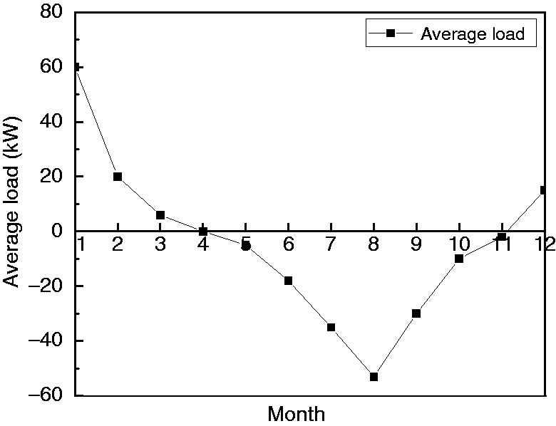
The monthly average value of building load.
Figure 10 shows the heat exchange rate comparison between the calculated and experimental results. Three conditions are selected with flow velocities of 0.13 m/s, 0.15 m/s and 0.17 m/s respectively. It shows that the calculated results agree well with the experimental results. When the capillary heat exchanger area is 244.8 m2, in the cooling mode, the corresponding heat transfer per unit area is 0.25 KW/m2, 0.28 KW/m2 and 0.29 KW/m2 by calculation. In heating mode, capillary heat transfer per unit area is 0.19 KW/m2, 0.20 KW/m2 and 0.21 KW/m2 by calculation. Capillary unit area heat transfer in the cooling condition is higher than that in the heating condition. The capillary heat transfer per unit area in experimental results is also shown in Figure 10.
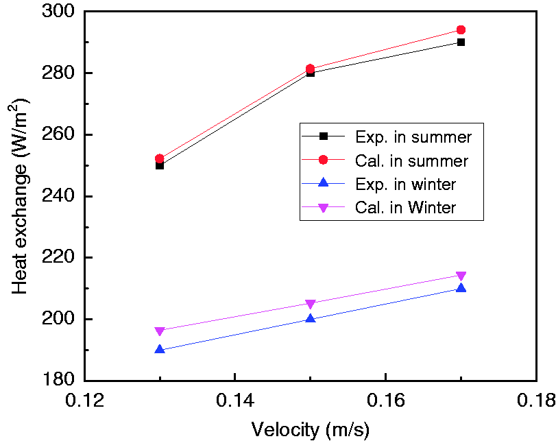
Heat exchange amount comparison in calculation and experimental.
The difference between the experimental results and the calculated heat transfer rate of the capillary heat exchanger in Figure 10 is analysed in both winter and summer conditions. The results of the margin error analysis of heat transfer are shown in Figure 11. In both winter and summer conditions, following the different velocity of the medium in capillary tubes, the errors are less than 5%, which indicates that both calculative and test heat transfer are consistent within an acceptable range.
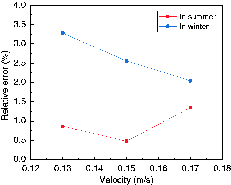
Heat exchange amount relative error analysis in summer and winter conditions by calculative and experimental value.
Based on the experimental data in winter and summer, it has been shown that the capillary design method is applicable for selecting the heat exchanger in the coastal area studied. For a typical building of 100 m2 in the northern coastal areas of China, the capillary tube numbers of each capillary grid are 1888. The capillary tube numbers meet the requirement of a total summer-cooling load of 15 KW and a total winter heat load of 6 KW. The results show that the calculation is consistent with the test data, which are proposed by the capillary design method, further verifying the rationality of the design method and the reliability of its application.
The technical challenges and barriers for the application of capillary heat exchangers are that it proposes a high requirement on the medium flowing in the capillary tube. To obtain a better heat transfer effect, the distance between capillaries should be large. The horizontal arrangement of capillaries covers a large area. In the case of blockage, it is not easy to maintain and remove obstacles during operation. In future, further research is proposed in this area, such as the variation of water level caused by the tide, durability, growth of algae, and economic analysis which would add practical values for the designers and users.
Conclusions
In this paper, a new capillary heat exchanger for use with heat pumps to reduce the energy consumption of buildings is proposed. This paper proposes the design and application of capillary heat exchangers as an energy acquisition device to extract energy from the seabed in coastal areas. The main factors affecting the heat transfer efficiency are the flow rate and the length of the capillary used in the heat exchanger. Meanwhile, other factors have a minor influence on the heat transfer rate.
The key contributions of this research are listed as follows:
An optimised design model of the capillary heat exchanger was established, which would fundamentally improve system performance and reduce irreversible losses. A capillary heat exchange formula is established based on minimum entropy production. The capillary heat exchanger design is considered as the research objective in the minimum entropy production process. The heat transfer performance and the thermal short-circuit consumption are regarded between the heat and the capillary effect. In summer and winter conditions, the maximum length of the capillary is calculated. When parameters such as heat transfer load, inlet capillary temperature, outlet capillary temperature, and water temperature are selected, the capillary length and numbers are determined by the number of heat transfer units. The optimum design method of the capillary heat exchanger is applied, which is based on the minimum entropy theory. For the capillary heat exchanger placed in the coastal area, in winter, seawater temperature is 3.7 °C, the heat transfer rate is 60 W/m2; when seawater temperature is 24.6 °C in summer, the heat transfer is 150 W/m2. The total number of capillaries and the number of grids is calculated in both winter and summer. This paper compares the heat transfer effect of a capillary heat exchanger for a typical building. The theoretically calculated values and experimentally determined values are compared. The results show that the capillary design method is validated by the experimental tests.
The limitation of this paper is that the different weather conditions in different climates are not considered. In future work, different types of building in each typical climate zone from different countries (e.g., UK, China and America) will be compared to consider the impact of climate changes on capillary heat transfer. That will further help to justify the application of capillary heat exchangers in buildings to reduce energy consumption and promote low carbon building design around the world.
Footnotes
Declaration of conflicting interests
The author(s) declared no potential conflicts of interest concerning the research, authorship, and publication of this article.
Funding
The author(s) disclosed receipt of the following financial support for the research, authorship, and/or publication of this article: This project was supported by the “National Natural Science Foundation of China a major plan”, and the “Thermal mass transfer and thermal performance index system of enclosure structure in extremely hot and humid climate zone in China”. (Grant No. 51590912).