
Abstract
It is important to limit dwelling infiltration to reduce energy demand and help meet national climate change commitments while concurrently providing sufficient ventilation to deliver adequate indoor air quality. DOMVENT3D is a model of infiltration and exfiltration that assumes a linear pressure distribution over any number of uniformly porous facades and integrates the airflow rate in the vertical plane to predict the theoretically correct airflow rate through them. DOMVENT3D is a new development of an existing two-dimensional model of infiltration that provides more opportunities for investigating a greater number of dwellings than was previously possible. Initial testing suggests that DOMVENT3D is mathematically robust and is suitable for modelling a wide variety of dwelling types and geometries to assist engineers and policy makers.
Practical application: The modern building services engineer may be required to model airflow networks in a building to balance the conflicting needs of energy consumption reduction and occupant health. Limiting exfiltration is one method of reducing heat losses from a building and so there is a need to model it accurately. This article presents a new model of infiltration and exfiltration through a uniformly porous facade that can be incorporated within advanced complex airflow network tools or applied using a simple spreadsheet.
Introduction
The infiltration of cold air and the concurrent exfiltration of conditioned air through adventitious openings in the thermal envelope of a dwelling can be a significant component of its heating load. Measuring infiltration is technically difficult, invasive and expensive and so it is often inferred from a measurement of air permeability, the rate of airflow through the fabric of a building measured at a steady high pressure difference, normally 50 Pa, when the effects of wind and buoyancy forces are effectively eliminated. 1 This inference is also problematic 2 and so there is a clear need to predict dwelling infiltration theoretically, which is both cheap (in the sense that no measurements area required) and computationally quick. There are two approaches commonly used to model infiltration. The first approach relies on the knowledge of the location of adventitious openings, known as air leakage paths (ALPs), their geometry or expected losses across them. Each ALP is specified explicitly and appropriate leakage characteristics are derived either from measurement or from appropriate sources in the literature for specific building components. 3
However, it is suggested that ‘there is insufficient data available in the literature to justify [anything] other than a uniform distribution’ 4 of porosity. The second approach to modelling infiltration uses an appropriate number of ALPs, equally spaced in the vertical plane to account for buoyancy driven flow and sized according to the dwelling’s permeability. This is known as the multiple element approach 5 and it is advised that 11 equally spaced ALPs is an adequate number. 2
An elegant development of this approach, when the number of ALPs is large, is the method proposed by Lyberg 6 and Lowe. 7 The basic equations proposed by Lyberg are additionally used to model airflow through large openings 5 but his formulation also handles airflow through envelopes with a wide range of properties; a brief discussion of the fundamental differences is given in ‘Initial tests’. Lowe’s two-dimensional infiltration model, known as DOMVENT, assumes a linear pressure distribution over a uniformly porous facade and integrates the airflow rate in the vertical plane to predict the theoretically correct airflow rate through that facade. Deru and Burns 8 have extended this work by defining equations for the situation where both infiltration and exfiltration occur simultaneously through a single facade driven by natural forces. However, the approach does not consider the effects of a mechanical system on facade infiltration and exfiltration rates. The simplicity of Lowe’s DOMVENT model 7 and its implementation using bespoke MATLAB 9 code means that the calculation and post-processing time is significantly less than that for conventional airflow analysis tools, such as CONTAM 10 and AIDA, 3 two independent validated airflow analysis tools. These tools do not have an airflow path that specifically characterizes infiltration and so must follow the multi-element approach described here. The predictions of DOMVENT have been compared against those of established envelope flow models 2 and is used to investigate energy use and CO2 emissions in dwellings 7 and the relationship between permeability and infiltration in conjoined dwellings. 2 Thus, DOMVENT is a useful tool for undertaking the simulations necessary to investigate the infiltration one might expect to find in a dwelling subjected to varying weather conditions. However, the current formulation of DOMVENT described in the literature is exclusively for a cuboid dwelling with two identical exposed facades when internal and external temperatures are unequal. This constrains its application to the modelling of mid-terrace houses and some apartments. Mid-terrace houses account for only 19% of the English housing stock, 11 whereas end-terrace, semi-detached and detached houses account for 53% of the stock. 11 Accordingly, if one is also to have confidence in the predictions of infiltration in dwelling types that comprise the majority of the English stock, a more versatile form of DOMVENT is needed that is able to consider any number of vertical facades with differing geometries.
This article addresses the limitations of DOMVENT by developing a three-dimensional model of infiltration and exfiltration known as DOMVENT3D. Here the term ‘3D’ implies the potential of the model to predict infiltration and exfiltration in three-dimensions even if it is not always applied in this way. In ‘Modelling infiltration’, the model is derived from first principles so that it can predict the infiltration rate of any dwelling with cuboid geometry. Uncertainties and limitations are discussed and the model is corroborated against the predictions of CONTAM. In ‘Applications’, suitable applications of DOMVENT3D are discussed.
Modelling infiltration
Consider a dwelling of height H (m), depth D (m) and width W (m), with one or more exposed facades (see Figure 1, which shows a cuboid representation of a dwelling, and Figure 2, which shows a cross-section through one of any number of vertical facades). When a building contains no mechanical ventilation system or a perfectly balanced mechanical ventilation system, mean infiltration and exfiltration rates are equal in magnitude and opposite in sign. They are a function of the geometry of the building, its local environment and the prevailing meteorological conditions. When an unbalanced mechanical ventilation system is present, the rates of infiltration and exfiltration are generally unbalanced. Cuboid dwelling of height H, width W and depth D. Facades 1 and 2, dwelling front and back; facades 3 and 5, sides (exposed if detached or internal if terraced); facades 4 and 6, ceiling and floor. Vertical cross-section through a facade of height H, under pressure from: (a) action of the wind and (b) stack pressure. The resulting (c) linear pressure distribution gives an (d) airflow distribution with areas of (1) infiltration and (2) exfiltration, separated by a neutral point z0 .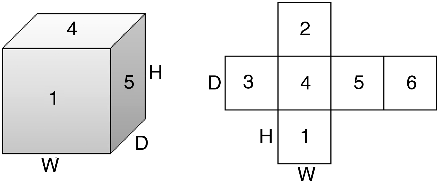

A general model
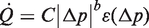
Most models of infiltration and exfiltration use a power law relationship between the pressure difference Δp (Pa), across an adventitious opening, known as an ALP, and the volume flow rate
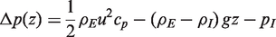
The modelling of specific ALPs is appropriate if their locations are known but in most cases they are not. In the absence of a priori knowledge on their locations, it is common to assume that a vertical wall or facade is uniformly porous.2,4 The vertical pressure distribution over the facade of a building is a function of the action of the wind, the difference between internal and external air densities, known as the stack pressure, and a change in internal pressure that occurs to balance mass through all openings in the building (see Figure 2 (a)–(c)). Accordingly, the pressure difference across a point on the facade at a height z (m) above floor level is given by
1
A number of ALPs are defined in the vertical plane to model a uniform distribution of porosity of any number of facades. The airflow rate through and pressure difference across each ALP is defined by equations (1) and (3), respectively. The two equations are solved by varying
DOMVENT3D: An integrating infiltration model
When z is a variable and all other parameters are constant, the pressure difference across the facade varies linearly with z and equation (3) has one root or equilibrium point. The height at which the root occurs is known as the neutral height z0 (m). When
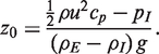
Equation (4) shows that as
The pressure difference over a facade can also be described with reference to z0 thus

If equation (1) is now assumed to be the flow rate through an infinitesimal section dz (m) of a facade in the vertical plane due to a pressure difference across it, it can be rewritten to describe the total volume flow rate of air through the facade,
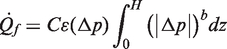
Now, C can be expressed as

Lowe
7
states that equation (1) can be rewritten to show that the dwelling air leakage rate,
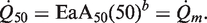
Here,
Equations (5), (6) and (7) are combined so that
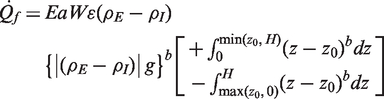
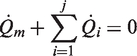
Note that for simplicity, the flow function input is reduced to the difference between the air densities because the difference between these parameters governs the airflow direction. Each of the integral limits of equation (9) are taken to be zero if the lower limit of integration exceeds the upper. The integration of equation (9) describes both infiltration and exfiltration (see Figure 2) and can be split into two separate equations whose sum is equal to
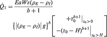
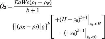
Ordinarily, equations (1), (2), (10) and (11) are solved numerically but there are three situations when an explicit solution is possible for a naturally ventilated cuboid dwelling whose external facades are of equal height. First, when u = 0 m/s and infiltration is solely attributable to buoyancy forces, z0 = H/2 m. Second, when a building has two exposed facades, the mean of the neutral heights on the windward and leeward facades equal H/2 m. Finally, a single-sided dwelling has a neutral height of z0 = H/2 m for all environmental conditions. These situations are true because: (a) an average value of air density is used in equation (7) and (b) the permeability of the exposed facades is considered to be uniformly distributed and so the area of exposed facades that provide infiltration must equal the area of exposed facades that provide exfiltration.
DOMVENT3D only requires three equations to model the airflow rate through a uniformly porous facade and a maximum of two equations are required at one time. This represents a considerable simplification of the multiple element approach and a development of the original DOMVENT model.
Model limitations
The application of equation (1) to airflow through a single ALP and to airflow through a whole building, characterised by a number of ALPs, is an approximation. The coefficients that describe the airflow through such a building are, in reality, not always constant but the assumption of constant values is not a significant obstacle to the use of this fundamental equation in the way proposed by Lyberg. 6 Furthermore, the power law relationship described by equation (1) is the most widely used method of interpolating between measurements of air leakage rates 2 and so is used here. It is noted that the quadratic relationship is considered to be more accurate at operational pressure differences 1 and so a future version of DOMVENT3D may incorporate this approach.
Equation (3) assumes that pI and ρE are uniform and u and cp are not a function of z when z ≤ H. These assumptions restrict equation (2) to low-rise buildings. Here, Liddament 12 suggests that mean pressure coefficients are appropriate for low-rise buildings of up to three storeys and so this limit is adhered to here. The authors are unaware of any empirical evidence of temperature distributions in dwellings that could be used to add another density term to equation (3) to accurately describe stratification. Moreover, the consideration of stratification increases the computational complexity of the model. Thus, it is acknowledged that although ignoring the effects of stratification introduces uncertainty into the model, it is nevertheless considered to be an acceptable trade-off between model complexity and prediction accuracy. 5
Initial tests
The theory that underpins this article can handle envelopes in which flow varies continuously from turbulent (b = 0.5) to laminar (b = 1); see equation (1). It can therefore be configured for comparison against the two-way single-opening ventilation element (TWSO) that is used to model airflow through large doors and windows by CONTAM,
10
a validated multi-zone ventilation and pollutant transport model. The TWSO requires input of the width of the opening, height and discharge coefficient, Cd (akin to E, the relative leakage area). The flow exponent is fixed at b = 0.5 and the minimum value of Cd is 10−3. These restrictions make the TWSO unsuitable for modelling a porous facade because b is too small— for adventitious cracks
3
b is between 0.6 and 0.7— and Cd is too big; for example,
2
E = 1.64 × 10⁻⁴ for an archetypal apartment with a permeability of 10 m3/h/m2. Nevertheless, a numerical corroboration of DOMVENT3D against the TWSO element is possible and so a single DOMVENT facade and TWSO element are modelled when Cd, E, W and H are set to unity, b = 0.5, g = 9.81 m/s2 and u = 0 m/s. The internal and external air temperatures are TI = 292.15 K and TE = 282.15 K, respectively. The air density is given by
The differences between the predictions of CONTAM and DOMVENT3D for both buoyancy-driven flow and combined wind- and buoyancy-driven flow are negligible and so can be said to be in agreement.
Applications
When comparing DOMVENT3D to most models of infiltration, its consideration of the physics is relatively complex because it assumes a linear pressure distribution over a uniformly porous facade and integrates the airflow rate in the vertical plane to predict the theoretically correct airflow rate through that facade; yet, its application is simple. Thus, DOMVENT3D can be used to make many predictions quickly, making it an ideal tool for predicting the infiltration rates one might expect in a stock of buildings in reasonable computational time. DOMVENT3D’s limitations (see ‘Model limitations’) constrain its application to the evaluation of low-rise buildings, such as houses. In England, there are some 22.3 million dwellings;
11
yet the number of measurements of dwelling air permeability made in the existing stock is limited.13,14 Although the air leakage testing of all new dwelling developments is now mandatory, 88% of the stock was built before 1990
11
when tests were not required. Therefore, the government formulates its policy on the retrofitting of energy efficiency measures designed to meet climate change mitigation commitments using a limited quantity of data. A forthcoming article by the authors uses DOMVENT3D to investigate infiltration rates in English dwellings following a study of infiltration rates in the U.S. housing stock using CONTAM.
4
The latter study
4
assumes uniform porosity, which means that it applied the multiple element approach, although this is not stated. Accordingly, the accuracy of their predictions could be improved if the TWSO element is amended to allow
ALPs in horizontal facades (floors and ceilings) can be defined by equations (1) and (3) and incorporated within DOMVENT3D using equation (2). When a simple single zone airflow model is required, equations (10) and (11) can be easily incorporated within AIDA 3 or placed into an Excel spreadsheet and solved using its ‘Goal Seek’ command.
To demonstrate the potential of DOMVENT3D, it is used to estimate the range of infiltration rates one might expect to find in a typical UK detached house
15
located in open, rural and urban terrain. The house has dimensions W = 6 m, D = 8 m, and H = 4.8 m, a volume of 230.4 m3, an envelope area of 230.4 m2 and an air permeability of 10 m3/h/m2. The house has a loft and a suspended floor and so the entire thermal envelop is assumed to be permeable at a pressure differential of 50 Pa. A typical flow exponent
3
of b = 0.66 is applied and so, using equation (8), the relative leakage area is calculated to be E = 1.52 × 10⁻⁴ when Infiltration rate (h−1) envelope of a typical detached house located in open, rural and urban terrain for temperature differences of 5, 10 and 15 K.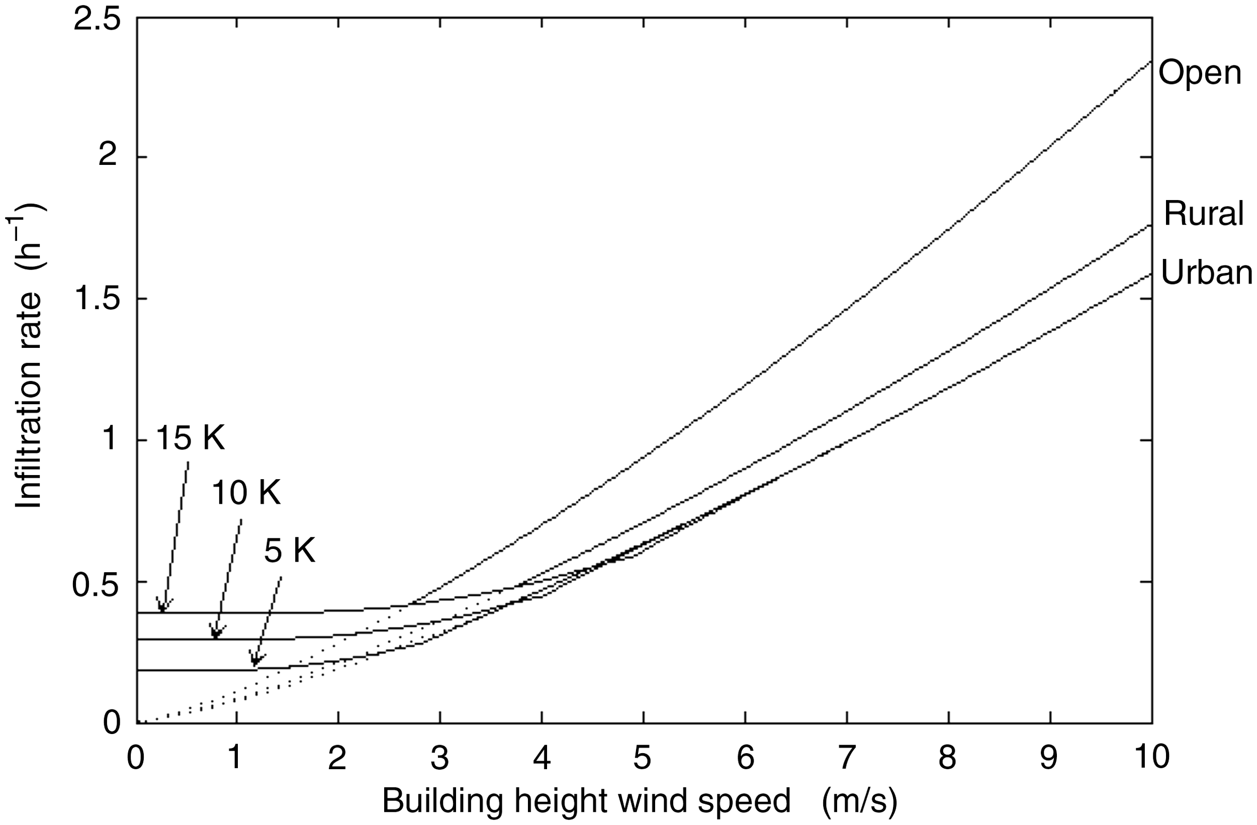
Conclusions
This article presents a brief analysis of approaches used to model infiltration in low-rise buildings, such as dwellings, and describes a new general model of infiltration known as DOMVENT3D. The theory that underpins this article can handle any number of facades where airflow through them varies continuously from turbulent to laminar and the pressure differences across them are caused by both mechanical and natural forces. The model was tested against CONTAM with encouraging results. It is shown that two simple modifications to CONTAM’s TWSO ventilation element would allow it to make improved predictions of infiltration rates. Finally, with increased confidence in it predictions, it is proposed to use DOMVENT3D to investigate the infiltration rates one might expect to find in UK houses and thus to help policy makers make informed decisions on the installation of energy efficiency measures in houses.
Footnotes
Funding
The authors are grateful to the European Commission for its funding of the PURGE project by its 7th Framework Programme under grant agreement number 265325.