
Abstract
In this paper, a novel approach for tracking moving structures in multiphase flows over larger axial ranges is presented, which at the same time allows imaging the tracked structures and their environment. For this purpose, ultrafast electron beam X-ray computed tomography (UFXCT) is being extended by an image-based position control. Application is scanning and tracking of, for example, bubbles, particles, waves and other features of multiphase flows within vessels and pipes. Therefore, the scanner has to be automatically traversed with the moving structure basing on real-time scanning, image reconstruction and image data processing. In this paper, requirements and different strategies for reliable object tracking in dual image plane imaging mode are discussed. Promising tracking strategies have been numerically implemented and evaluated.
Keywords
Introduction
Fast imaging techniques are essential experimental tools in fluid dynamics research, particularly for the investigation of multiphase flows. Such flows are to be found in, for example, chemical reactors, thermal power plants, oil and gas processing, refrigeration systems, fluid transport systems and others. Multiphase flows are inherently complex due to the co-existence of multiple phases with different physical properties and highly deformable interfaces; for example, in gas-liquid and liquid-liquid flows. The modelling and numerical simulation of multiphase flows with computational fluid dynamics (Brennen, 2005: 20 ff.) require validation data from experiments. For such measurement techniques with high temporal and spatial resolution are needed. Particularly, non-invasive imaging is of great attractiveness (Reinecke et al., 1998). However, today there is no multiphase flow imaging technique available, which gives a full three-dimensional (3D) view of opaque multiphase flows at high speed and resolution. As an example, we address a simple bubbly flow in a pipe or vessel, that is, a coexistent flow of continuous liquid and disperse bubble in a flow channel. As such, it would be ideal to “see” all bubbles in a given volume, that is, pipe or column section, at a spatial and temporal resolution that discloses the dynamics of the bubbles themselves, the dynamics of their interfaces and their geometric relations to other bubbles. Of course, it would also be of interest to know the local continuous liquid velocities. As this is all not possible today, an alternative would be to have a fast cross-sectional, that is, two-dimensional (2D) imaging, with a capability to track a moving structure, like a bubble. This would at least allow to study a single bubble and its environment dynamically. In the following, we will describe our approach to solve this task by tracking structures in a flow with an ultrafast X-ray tomography device. Before that, we will briefly review dynamic imaging techniques for multiphase flows, to provide a good start into the subject.
Today, there are a few fast flow measurement techniques available for scientists and engineers. Most prominent are high-speed cameras. However, they are seldom applicable for multiphase flows as such are inherently opaque. The same holds for ultrasound-based imaging techniques. Techniques, which are in principle suitable for multiphase flows, are electrical tomography, radiation-based imaging techniques and magnetic resonance imaging. Hence, we will first briefly review these techniques with a focus on their current capability to deliver a full picture of, for example, a bubble flow in a pipe or column.
Electrical tomography, with its variants electrical capacitance tomography (ECT), electrical resistance tomography (ERT) and electrical impedance tomography (EIT), is able to recover structures with different electrical properties in multiphase flows. The techniques can be made quite fast and have a certain 3D imaging capability (Xie et al., 1995). However, their spatial resolution is very limited, which hampers tracking of dedicated structures.
Transmission imaging techniques based on radiation can be classified into radiographic and tomographic imaging. Fast radiography is known for X-rays (Boden et al., 2014) and neutrons (Kaestner et al., 2011a, 2011b). X-ray radiography may be used and has been implemented in the form of X-ray stereoscopic particle tracking (see below). Conventional X-ray tomography, that is being used in medicine and for non-destructive testing, is generally too slow as it requires mechanical movement of system components (Kak and Slaney, 1988). An exception is ultrafast X-ray tomography, which we address in this study (Fischer et al., 2008).
Magnetic resonance imaging (MRI) provides high spatial resolution and 3D imaging capacity. However, the fastest MRI scanners achieve up to 50 fps (frames per second) (Müller et al., 2007; Tayler et al., 2012b), which is still quite slow compared with the time scales of multiphase flows. Recent applications of ultrashort echo time MRI have attempted to track moving structures in fluidized beds (Fabich et al., 2017) and bubbly flows (Tayler et al., 2012a) at 40 fps. A main advantage of MRI is the simultaneous measurement of liquid-phase velocities that cannot be achieved by radiation-based tomography methods. However, the relatively small volume of investigation limits the application to snapshots of bubble swarms rather than visualizing their paths and dynamics over a larger range.
Besides imaging techniques, there exist also pure structure tracking techniques for multiphase flow. Such are CARPT (Degaleesan et al., 2001), PEPT (Cole et al., 2010), and X-ray stereoscopy (Nadeem and Heindel, 2018). In PEPT and CARPT, radioactively marked tracer particles are tracked over a longer period. As they are pure tracking techniques the surroundings of the tracked structures (particles) are not disclosed. X-ray stereoscopy obtains the position of high-contrast particles from triangulation. To some degree surrounding structures are disclosed in the associated X-ray images. However, as these images provide no good depth information, the 3D imaging capacity is rather low (Nadeem and Heindel, 2018).
Ultrafast X-ray tomography is a relatively new fast imaging technique that comes very close to the given requirements. It bases on X-rays, provides high frame rate of up to 8000 fps, 1 mm spatial resolution and dual plane imaging (Bieberle et al., 2012). As this technique yet has only 2D imaging capability, though in two planes simultaneously, structure tracking out of the imaging planes is not possible. To qualify this technique for structure tracking, a fast positioning system for the scanner has to be implemented and a fast data analysis strategy for controlling the system has to be developed. The latter development has been started already in our group with the transfer of the data processing onto graphic processing units (GPU) (Bieberle et al., 2017; Frust et al., 2017). This now gives short enough latency times for real-time axial scanner position control.
In the scope of the control concept the two imaging planes of the X-ray scanner act as a pair of binary structure sensors. Many control schemes for binary sensors or binary sensor networks (BSN) are known from the literature. However, their application is limited to either unidirectional continuous processes, for example, liquid level control (Wang et al., 2003), or multi-dimensional positioning problems for zero-dimensional objects, for example, tracking of persons across various rooms, (Bai et al., 2015). Thus, Liu et al. (2013) proposed a strategy for extraction of velocity and size of a circular object moving at constant speed using a set of transmitter-receiver style binary sensors. However, the extracted information is used neither to control the process nor to track it actively by repositioning the sensors.
There are also various strategies for image-based control, for example, based on high-speed camera footage (Hutchinson et al., 1996). They are, however, only applicable for controlling processes within the imaging region. Combining the available concepts, we propose a control strategy for image-based control of processes occurring normal to the imaging plane(s). Here, instead of a BSN, only a pair of controllably traversable binary sensors is used.
To track a moving structure, an effective position control of the ultrafast X-ray CT scanner must be provided, employing a low-latency trajectory generation. For that a so-called model predictive control approach is most suited in which the target’s position changes are suitably modelled. Furthermore, constraints regarding the maximal applicable velocity and acceleration need to be included. This requires iterative computation techniques that are critical in terms of real-time operation (Kim et al., 2007; Neunert et al., 2016). Current analytic approaches do not include such a movement model (Haschke et al., 2008; Ruppel et al., 2011). However, for tracking of a temporarily non-visible moving target, such as a bubble moving between imaging planes, this is indispensable. Thus, a time-optimal, analytic trajectory generation is proposed that complies with maximum velocity and acceleration constraints. A double-setpoint controller is employed based on the periodic modelling of the structure’s movement with a parabolic position profile. Similar to the receding horizon approach, the model parameters are updated in every time-step and only the optimal control output for the next time step is used. Different from classic receding horizon control, the analytic solution allows modelling the movement up to the current control target instead of exploring only a fixed prediction horizon.
Materials
The ultrafast electron beam X-ray CT scanner
As shown in Figure 1a, the ultrafast electron beam X-ray CT scanners use an electron beam that is focussed and deflected onto a circular tungsten target to generate a rapidly rotating X-ray focal spot along two staggered paths without any mechanical movement of components. Data acquisition is performed by a radiation detector that comprises two distinct rings of CdTe detector pixels arranged concentric to the X-ray target. The CT scanner under consideration offers a circular imaging area with a diameter of
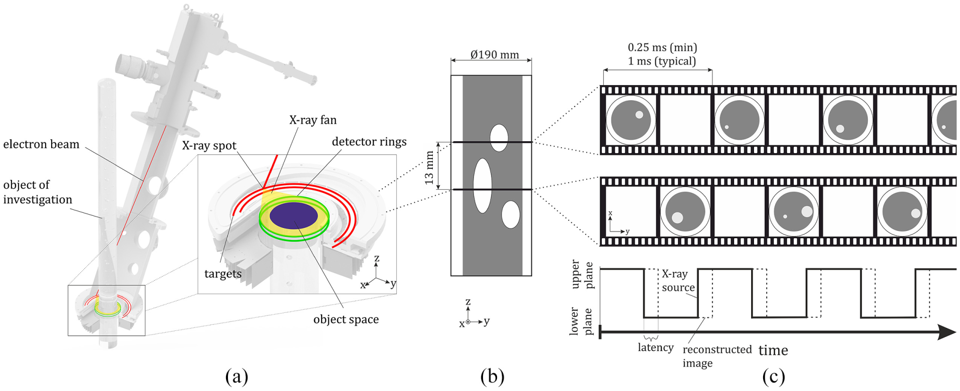
(a) Principle sketch of the ultrafast electron beam X-ray CT, (b) vertical view of the object area. Horizontal lines indicate the imaging planes and (c) principal order of alternating cross-sectional images per plane over time. Latency is sketched for the real-time image reconstruction.
Image reconstruction is currently performed offline. That is, the digitized signals of the radiation detectors are temporarily stored in the random access memory of the detector electronics before they are being transferred to the host computer after completion of a scan (Bieberle et al., 2017). There, image reconstruction and post-processing is done at a later time.
For structure tracking, real-time image reconstruction as well as control strategies to traverse the CT scanner are needed. Data processing pipeline systems (Frust et al., 2017; Kopmann et al., 2016) seem to be proper tools for that. For that we evaluated three different traverse control concepts, as explained in the following.
Tracking strategy
A moving structure, in this case represented by a rising gas bubble, is fully described by the following set of one-dimensional parameters (Figure 2a): the current position
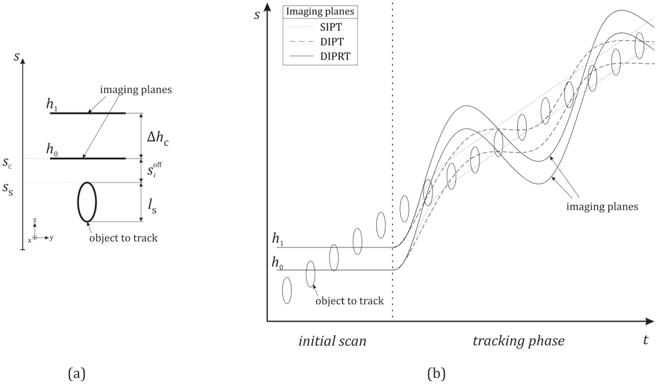
(a) Description of important system parameters. (b) Qualitative scanner movement for the different control strategies.
To track the moving structure, the scanning position
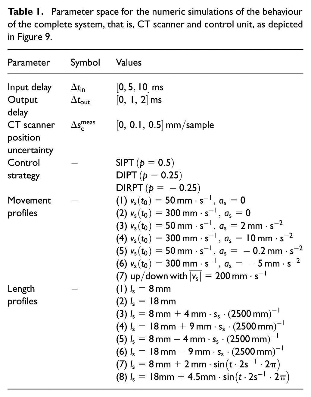
Parameter space for the numeric simulations of the behaviour of the complete system, that is, CT scanner and control unit, as depicted in Figure 9.
Parameter extraction of the moving structure
No matter which tracking strategy will be applied, parameters of the investigated object have to be extracted initially from the image pair data. However, as recognizable from Figure 1c, in a single image plane, a small and slowly rising structure leads to the same image sequence as a tall and fast rising structure. Thus, for the extraction of the structure velocity, the images from the second imaging plane
Determination of structure velocity and axial dimension using dual-image mode of the CT scanner.
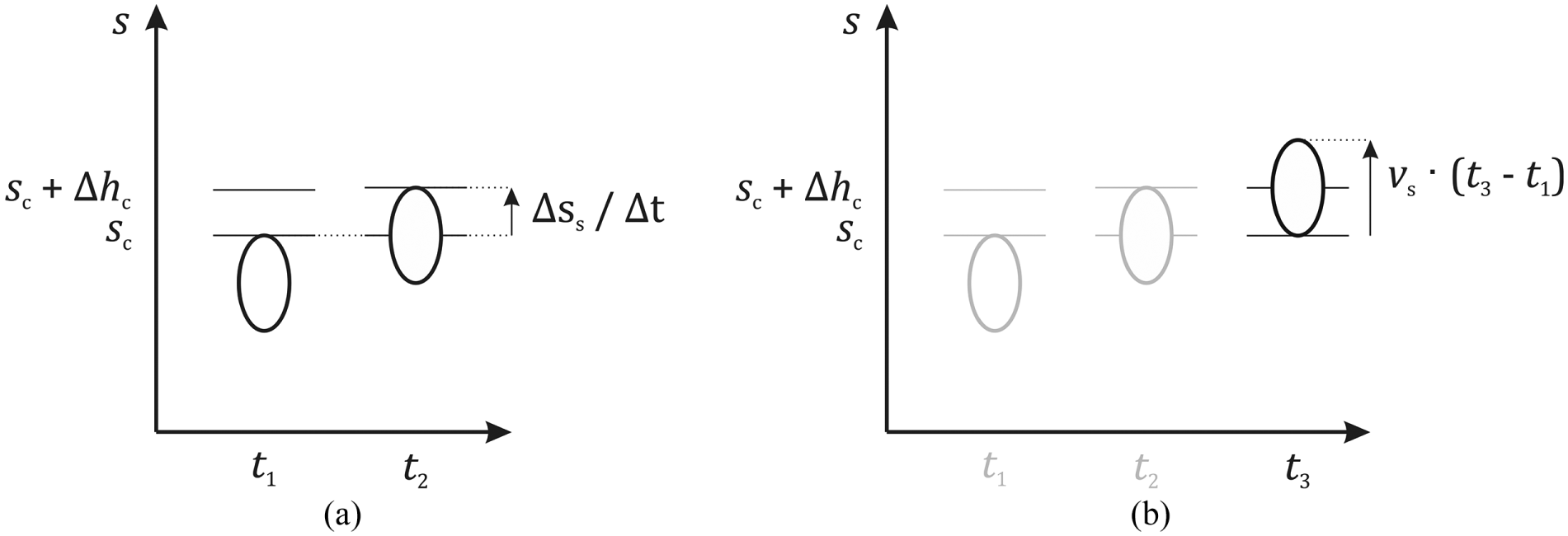
The time interval
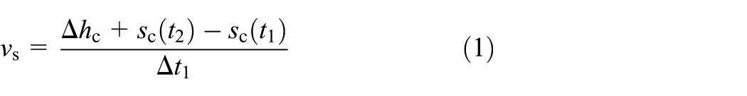
Secondly, the time interval

using the latest previously estimated velocity
By following an axially moving structure, its boundaries are tracked every time one crosses one of both image planes. Between these crossing events at times
To distinguish between the structure’s upper and lower boundary, six different CT scanner states
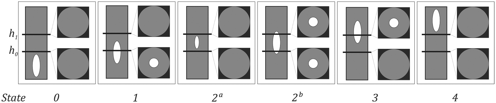
Defined CT scanner states with corresponding cross-sectional images to distinguish between upper and lower structure boundary.
States
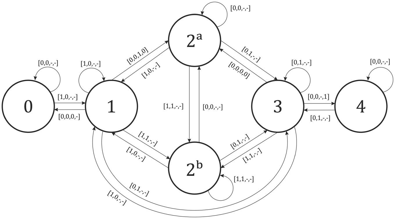
State transition graph with valid state transitions and their respective transition conditions.
Each transition is used to identify the tracked structure’s upper or lower boundary, respectively. For example, transition
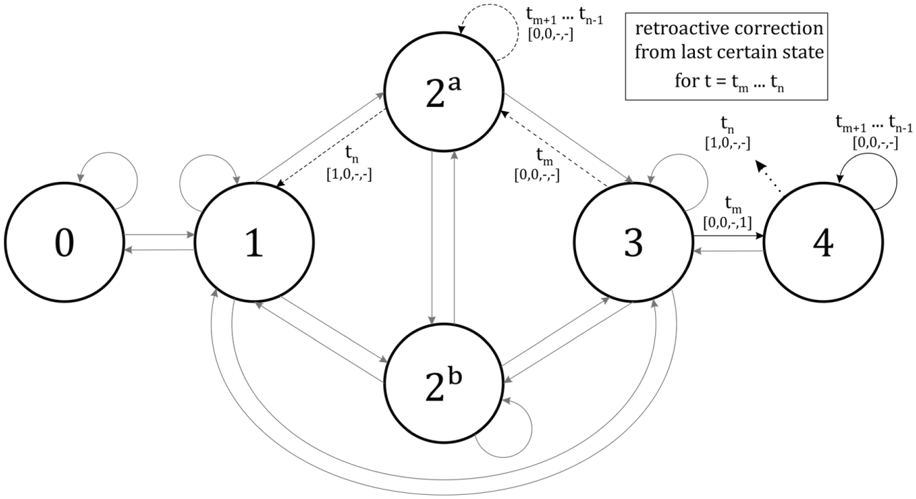
Exemplary retroactive correction for invalid state transitions.
In case such an invalid transition is detected, the system falls back to the latest certain state at time
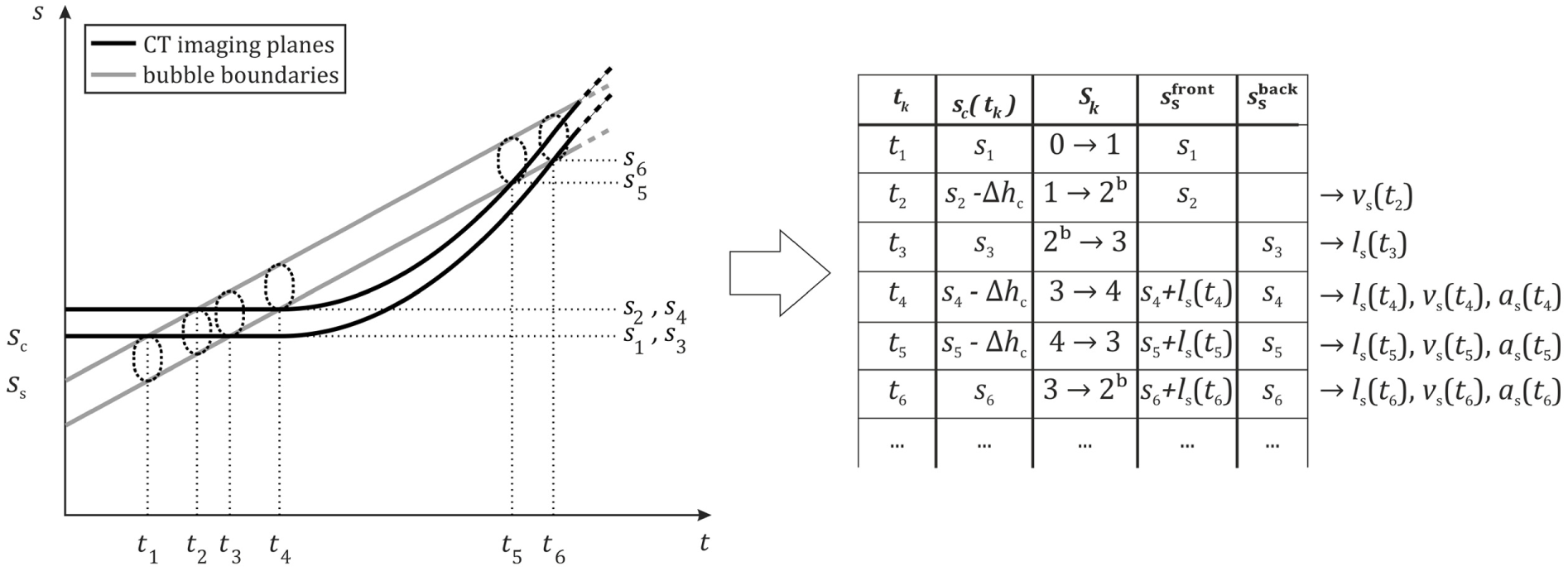
Concept of evaluating structure’s front and back using image-pairs and the history of the CT scanner states using the example of the initial investigation of structure parameters required at the beginning of each of the aforementioned structure tracking strategies.
Motion planning for the CT scanner
Depending on the above given tracking strategy and the latest parameter estimation of the structure, a new target position


The structure’s movement profile is described by
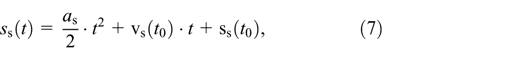


For better readability and without loss of generality, terms in the form
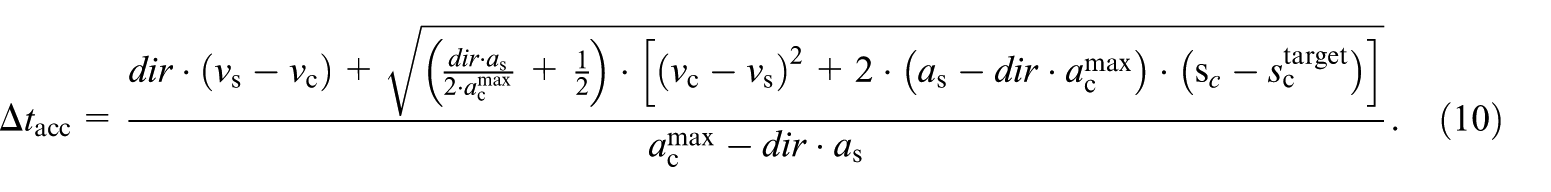
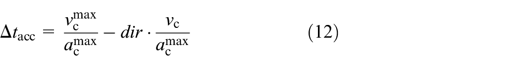
Therein, the directional term
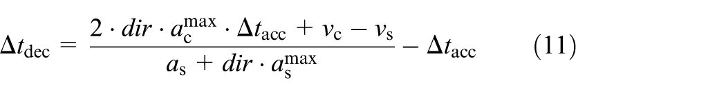
can be calculated. Otherwise, an intermediate phase segment with constant and maximum velocity of duration
considering the current velocity
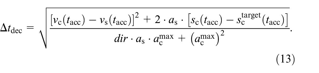
Lastly, the intermediate time interval
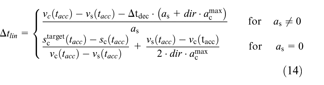
Finally, equation (15) compiles the minimum traverse time
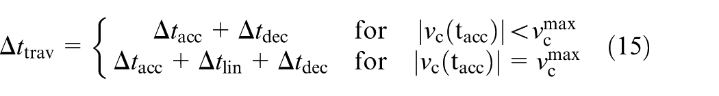
on which the scanner will hit its target scanning position. The trajectory is updated every master clock cycle and passed as input to the scanner’s positioning unit.
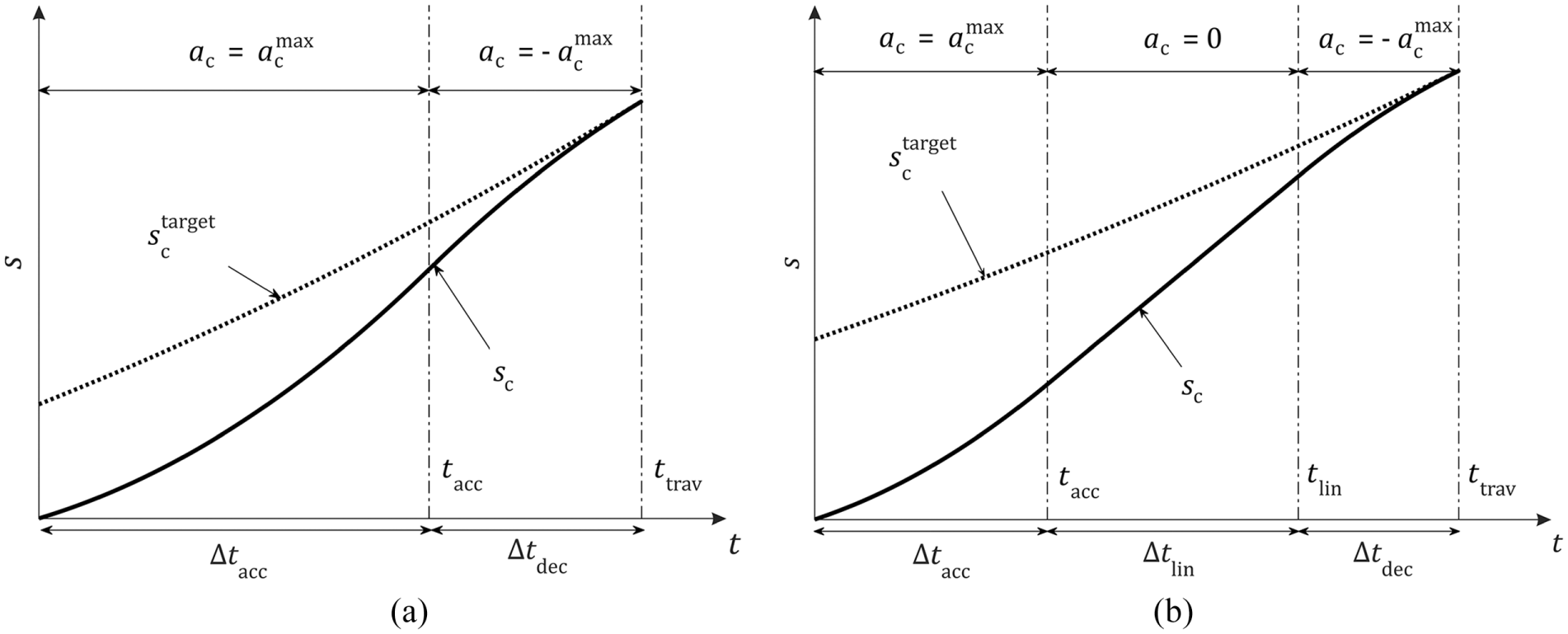
Velocity profile for the CT scanner (a) without and (b) with a constant velocity segment to be able to follow a moving structure.
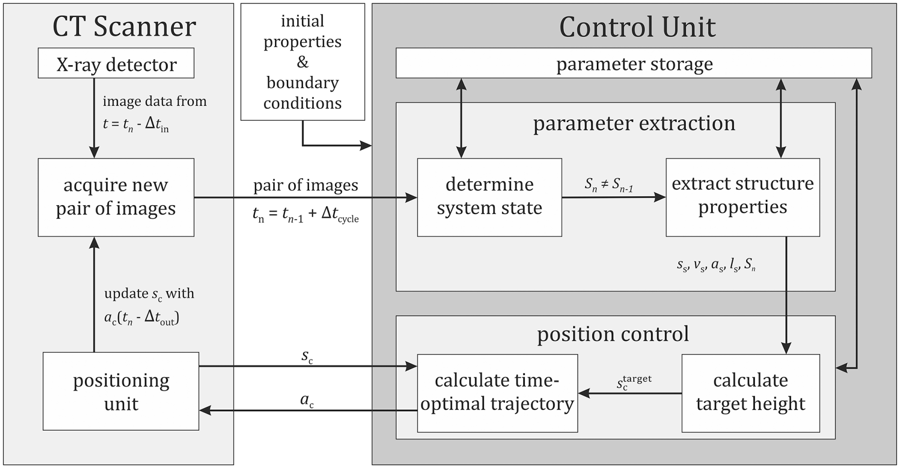
After presenting different tracking strategies and the parameter extraction procedure for the observation of dynamic structures, the entire control concept (Figure 9) can be concluded. As input parameters the continuously reconstructed image-pair stream as well as the current position of its imaging planes
Basic tracking sequence to determine a structure’s rising velocity and length using a dual-plane CT scanner.
Each time the CT scanner state
Results and discussion
To investigate the feasibility of the proposed control strategies the behaviour of the entire system, that is, CT scanner and control unit as depicted in Figure 9, has been simulated for various flow scenarios. For this, an artificial 1D logical phantom vector which resembles predefined structure motion and length profiles (see Figure 10) was used.
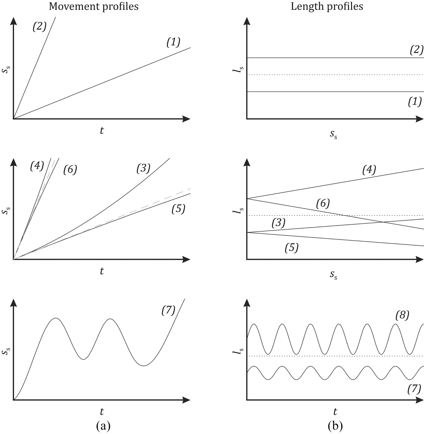
Simulated structure movements. a) Movement profiles with their respective indices (linear (1,2), accelerated (3,4), decelerated (5,6), up and down (7)) and b) length profiles (constant (1,2), linear increase (3,4), linear decrease (5,6), fluctuating (7,8)) along the test section. Dotted lines represent
To cover a wide range of technical applications different movement and structure length profiles have been simulated (see Figure 10). This set of parameters includes linear, accelerated, decelerated and up/down movement as well as constant, linearly increasing / decreasing and fluctuating structure lengths. The used values for the study are compiled in Table 1 with their respective indices. Combining all parameter variations, a total number of 4536 different parameter sets have been simulated.
During the simulation, the path and the velocity of the structure phantom is calculated for each current time step
In the real positioning system, the position

The CT scanner starts at standstill, that is,
Structure parameter extraction
To evaluate the tracking strategies regarding velocity information extraction, the momentary velocity estimations
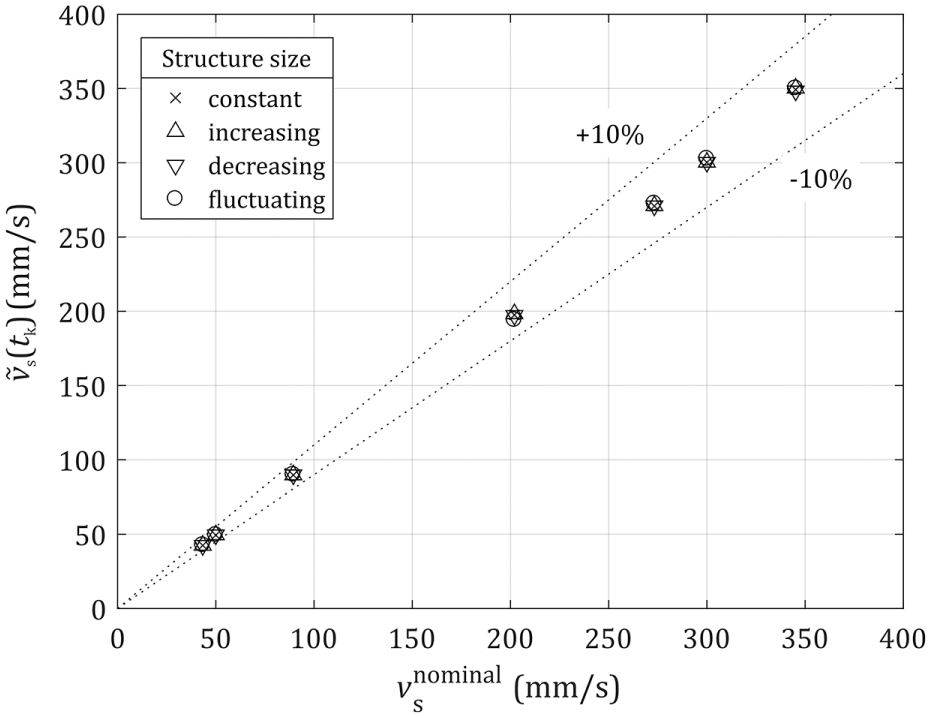
Median momentary velocity estimates for different movement profiles (standard deviation
Results at all sample points show an agreement between nominal velocity and median measured velocity
To evaluate the length estimation quality the momentary length estimations
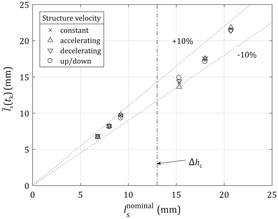
Median momentary length estimates for different movement profiles (standard deviations
Comparison of control strategies
As depicted in Figure 13a, all control strategies deliver similar velocity estimation results of about
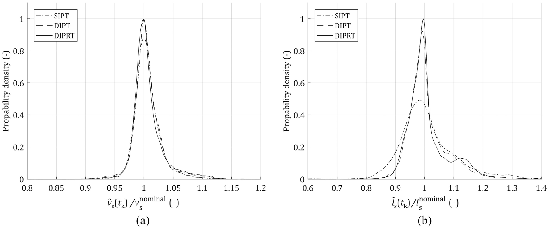
Comparison of feature extraction quality for different control strategies "SIPT", "DIPT" and "DIPRT". (a) velocity determination, (b) length determination.
Moreover, DIPRT’s length estimates show a bimodal distribution (see Figure 13b). Further investigations of length estimations for DIPRT in different structure length profiles reveal that this bimodal distribution occurs only for fluctuating structure length profiles (see Figure 14a).
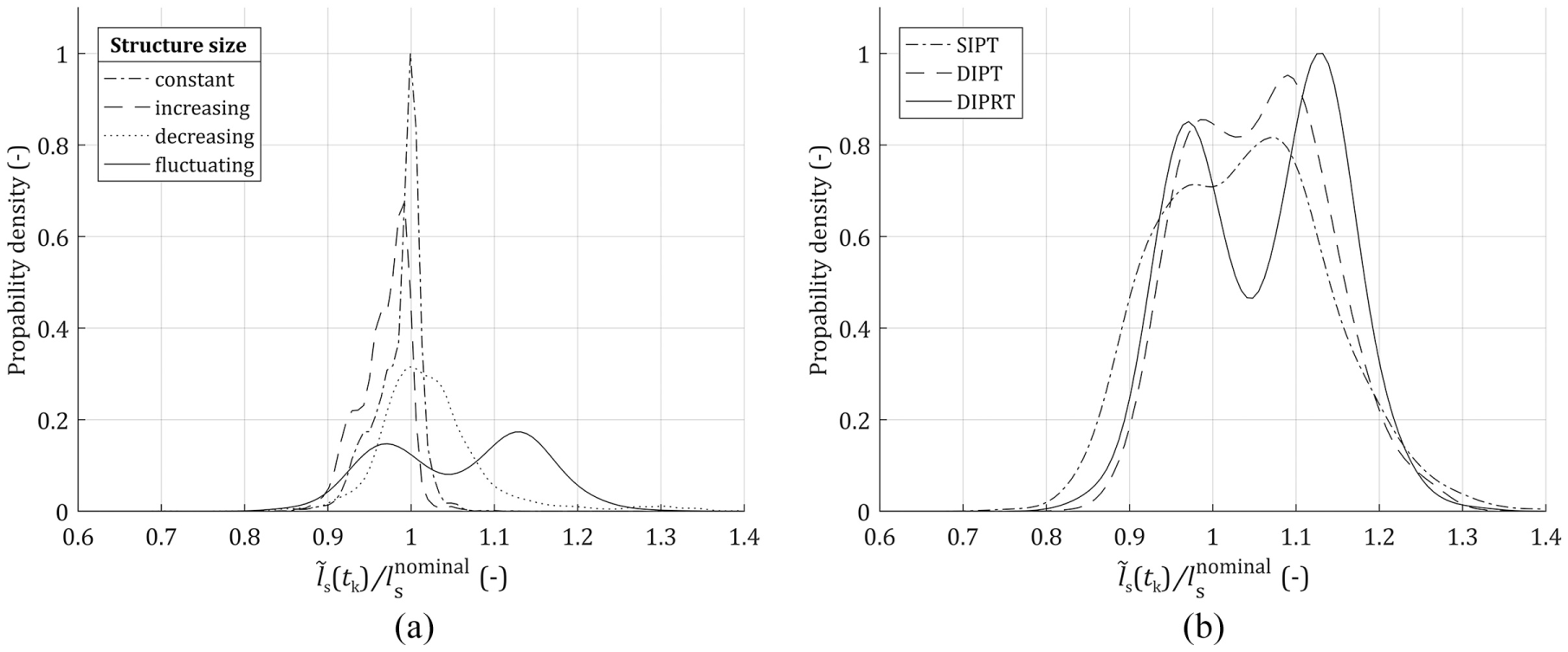
Length estimation distribution for (a) different structure length profiles using DIPRT strategy and (b) fluctuating length profiles using different control strategies.
This bimodal distribution occurs for all simulated movement profiles, delays
Increasing input latency
Conclusion
Different tracking strategies for the application of ultrafast X-ray tomography for studying moving structures in multiphase flows have been evaluated. A control scheme was proposed that provides a defined CT scanner positioning movement based on currently acquired image-pair data. Therefore, three different tracking strategies, namely Single-Image Plane Tracking (SIPT), Dual-Image Plane Tracking (DIPT) and Dual-Image Plane Re-Tracking (DIPRT), were discussed and evaluated by numerical simulation. All strategies promise very good velocity tracking results. However, SIPT is preferred for cases with constant structure shapes and lengths, for example, tracking of a tracer particle. To extract length and shape information for time-variable structure length and shapes, DIPT is more suitable for low disturbances. The DIPRT approach is preferred for detailed shape determination at high turbulence cases. Simulations have shown that DIPT and DIPRT were more robust than SIPT concerning the influence of time delays and position uncertainty.
Future work will focus on reliable structure recognition from the image pair data. Moreover, further post-processing steps to increase state estimation quality, and therefore feature extraction quality, using computationally complex techniques like particle filtering are of high interest.
Footnotes
Declaration of conflicting interests
The author(s) declared no potential conflict of interests with respect to the research, authorship and/or publication of this article.
Funding
The author(s) disclosed receipt of the following financial support for the research, authorship, and/or publication of this article: Financial support by Deutsche Forschungsgemeinschaft (DFG) is gratefully acknowledged (BI 1770/2-1).