
Abstract
The aim in this research is to utilize virtual prototyping to design and develop tightly fitting smart clothing integrated with transmission lines produced from conductive textiles using cut-and-sew technologies. The study evaluates how body posture dynamics affect the comfort and aesthetics of the garment by examining the tensile strain behavior of the element with conductive textile tracks. Virtual try-on technology was employed to assess garments with different geometry elements with conductive tracks. The results indicate that the sewn conductive tracks significantly limit the deformability of the basis material under low loads, and that up to four times less force is required to obtain 20% stretching deformations in systems incorporating Shieldex Balingen (SB), compared with those incorporating Shieldex Kassel (SK). The geometry of the element with conductive tracks is important for wear comfort during body movement, with simulations showing maximum deformations of up to 20% lengthening in the shoulder blade area. The best performance was observed in a variant 1 in which the SB conductive material extends 6 cm along the measurement line, with vertical tracks spaced 44 mm apart. Conductive element incorporating knitted fabric SB demonstrated good deformation properties, making it an excellent choice for tightly fitting smart clothing design. However, continued research and development is recommended to optimize these elements with transmission lines of conductive textiles, and further evaluation will be required to assess the durability and resistance to multicyclic stretching and washing.
Numerous studies and business reports have highlighted the rapid growth and promising opportunities in the smart clothing market. However, it is essential to note that, currently, smart clothing often falls short of meeting consumer expectations. Consumers desire smart garments that not only incorporate intelligent features but also align with their preferred designs, ensuring a seamless integration of the garment into an existing wardrobe.
Consumer expectations and preferences become critical when designing smart clothing. The technological functionalities considered should include comfort, convenience, design, and aesthetics.1,2 Balancing the capabilities of manufacturers and meeting consumer needs has become increasingly crucial in the journey toward the mass production and widespread adoption of smart clothing. 3 The success of smart clothing hinges on matching production technologies with market demands.
Understanding consumer needs and satisfying them in product design is a priority when it comes to clothing purchases.4 –6 This consumer-centric approach is equally relevant to the development of production technologies and the commercialization of smart clothing. Production companies and fashion brands are interested in entering the niche market of wearable technologies and smart clothing; however, companies note that extra investments are necessary for people training and technology adoption, 7 and designers lack knowledge of e-textiles and the design issues that emerge during the smart clothing product development process. 8 Some research on smart clothing product development process improvement has been conducted. To integrate an electronic system into a garment, additional sub-steps to the traditional design process are needed, as demonstrated by a five-step design framework developed for e-textile garments in a cut, make, and trim (CMT) factory setting. 8 However, the inconsistency between electronic systems and clothing manufacturing practices makes mass production of smart clothing a challenge for designers and a complex task for managers of integrated production.9,10
The term cut-and-sew describes fabric-based product manufacturing when pattern cutting and garment assembly in sewing lines are used to form 2D fabric into 3D garments. Production technologies that integrate current methods of clothing assembly can also be applied for the mass production of smart clothing. Reliable transmission lines for smart clothing have been produced using seams of conductive threads, hot air welding,11,12 and ultrasonic bonding. 13 It was demonstrated that correctly configured, designed, positioned, and calibrated seam stitching could enable the tracking of body movement. 14 Embroidery could be used to produce conductive tracks, 15 flexible circuits, and sensors. 16 Stitched methods for e-textile production ensure durable and flexible systems,17,18 and do not require major changes in garment design, pattern making, or production line planning.
Computer-aided design (CAD) methods are widely employed for clothing development in the era of digital production transformation. The use of 3D CAD systems for clothing design has attracted substantial interest from both researchers and the industry in the field of garment simulation. 19 In the industry, garment simulation, which includes virtual prototyping and virtual fitting techniques, has demonstrated significant benefits in minimizing both the time and cost associated with product development.19 –23 Through the simulation of virtual prototypes that accurately reflect fabric behavior, designers can rapidly assess the impact of design elements, such as design concepts, textile material selection, or garment construction, while achieving optimal fit, without relying on physical garment samples.24 –26 Utilizing 3D virtual garment simulation, the end product could be viewed, assessed, modified, and re-fitted without necessitating any actual cutting of fabric. This would give the designer significant opportunities to experiment with design, textiles, and seams, thus shortening the prototyping process during production.23,25 3D virtual garment simulation provides opportunities for niche and custom-made garments23 and is becoming an attractive tool for the development of smart garments. 27
Garment fit on the 3D body is the most important factor influencing appearance and comfort.28 –31 Clothing comfort directly affects human physiology and psychology and involves a number of independent factors, particularly movement comfort, thermal moisture comfort, tactile comfort, and pressure comfort.32 –34 The two main components that influence comfort and utility performance are the 2D pattern and the fabric’s mechanical and physical properties.19,35 The tensile property is an important functional property, which is related to the dimensional comfort. The bending property is of aesthetical importance, as it is the main influence on the drape of the garment over the body. 35
Virtual prototyping with 3D technology provides valuable insights into comfort and fit through the use of strain, stress, and pressure distribution maps, making it valuable in garment design and development.30,36 –40 The fit of a garment on a body model is an important factor in the design of comfortable, functional, and well-fitted garments. Today, the majority of CAD systems for garment pattern design have virtual 3D garment simulation software for garment prototyping and fit evaluation, 41 for example, Modaris 3D by Lectra, 3D Virtual Prototyping and 3D Suite by Optitex, VStitcher by Browzwear, and Tuka3D by Tukatech. Therefore, the use of a virtual environment to evaluate the fit of clothing is an important technique that will probably become indispensable in the future. Its application depends not only on the computer technology used, but also on knowledge related to evaluation of the resulting garment’s appearance and the virtual garment fit to the virtual body model.41,42
The fit and comfort of a garment are essential in the development of smart clothing. During wear, large deformations can occur, especially if the garment is tightly fitting; 43 therefore, stretching properties are very important to the performance during wear. 37 Incorrect fitting of smart clothing can affect the quality of the sensor readings; therefore, personalization of the garment and adequate positioning of on-body sensors are essential.44,45
As demonstrated by research into the application of 3D CAD for smart clothing,27,45,46 this tool can help to determine the correct positioning of sensors on the body and the optimal interface with the skin for effective electrode–skin distancing. Virtual smart garment fitting helps to determine sensing errors resulting from the fabric movement on the body surface during motion;47 –49 this is important for the personalization of smart garment designs and achieving the efficiency of certain performance metrics.
However, the application of existing product development and production technologies to suit the requirements of smart clothing functions and design 50 has not yet been extensively studied. There is still a lack of production process research for the analysis of clothing design and fit prediction through the evaluation of electrically conductive textile-joining technologies.
The aim of this research is to utilize virtual prototyping to design and develop tightly fitting smart clothing incorporating a conductive element, produced by applying cut-and-sew technologies with conductive textiles. The effect of posture dynamics on the comfort and aesthetics of the garment was assessed by evaluating the tensile strain behavior of conductive textile tracks and applying virtual fitting technology to garments with different geometries of conductive tracks.
In this research, technologies and methods common to sewn garment production are explored. It is shown that sewing technology can be used to create reliable transmission lines of conductive textile, and the comfort of the tightly fitting garments is assessed by Lectra Modaris 3D when the design of conductive textile element is modified. The obtained results prove that CMT and 3D CAD technologies can be applied for the development of comfortable smart clothing without restructuring of the processes used in the textile and clothing industry today, possibly speeding up the commercialization of smart clothing products with high added value.
Materials and methods
Sample preparation
Commercially available conductive textiles may be suitable for the production of smart garments using cut-and-sewn technologies, where the required shape of the conductive textile element is cut and joined to the garment parts using traditional sewing technology. In this research, conductive woven and knitted textile materials, produced by Shieldex, were used to create conductive tracks. The structural and mechanical properties of the chosen materials are given in Tables 1 and 2. Conductive textile materials have varying structural and deformation properties, and are suitable for the development of heating elements because of their low resistivity.
Specifications of basis material
Specifications of conductive material
Longitudinal direction is warp for woven fabric and wale for knitted fabric.
Transverse direction is weft for woven fabric and course for knitted fabric.
To investigate the mechanical properties, samples with conductive track were created using sewing technology. Conductive material tape, 10 mm wide, was cut in the longitudinal direction—as well as in the warp direction for Shieldex Kassel (SK) samples and in the wale direction for Shieldex Balingen (SB) samples. The conductive fabric was positioned along a basis material specimen with dimensions of 150 × 50 mm and fixed using two parallel seams (distance between seams, 8 mm). The parameters for the specimen sewing were as follows: seam class 5 (5.04.03) according to ISO 4916; 51 lockstitch 301 according to ISO 4915; 52 sewing machine, Juki DDL-888; stitch density, 4 cm−1; sewing thread, 100% polyester; 120 Nm.
Mechanical properties for the virtual simulation
The samples were characterized using several parameters. The area density parameter was determined according to EN 12127:1999. 53 The thickness was measured using a DPT 60 thickness gauge at a pressure of 1 kPa, according to EN ISO 5084. 54
The mechanical behavior of textile materials is generally measured using special measuring systems, such as the Kawabata Measuring System (KES-F) and FAST (Fabric Assurance by Simple Testing), which measure tensile, shear, bending, compression, and surface properties. 41 In this research for textile materials, mechanical properties were determined using the FAST measuring system. 55
Parameters of elongation, bending, and shear represent garment behavior during wearing and are required for the virtual garment prototype simulation.
The FAST bending meter was used to determine the bending rigidity, B. The bending meter uses the cantilever method.
56
In the test, a horizontal strip of fabric (5 cm × 20 cm) is clamped at one end and the rest of the strip is allowed to overhang and bend under its own weight. The bending rigidity B is calculated as

The FAST tensile test was used to measure the textile material elongation in the longitudinal and transverse directions at three fixed loads of 4.9 N/m, 19.6 N/m and 98.1 N/m, and produces extensions E5, E20, and E100 (%), respectively. 55 The Modaris 3D method uses E5, E20, and E100 to obtain a nonlinear tensile property of the textile material.
The FAST method subjects the test specimen to a constant maximum bias tensile stress of 4.9 N/m and obtains EB5; the bias extension is measured as a percentage.
55
The shear rigidity G is calculated as

Virtual simulation
A tightly fitting jacket was chosen as a prototype for virtual garment simulations. Modaris (CAD Lectra) software was used and a garment pattern of size M was designed for try-on using a virtual mannequin (height, 188 cm; chest, 104 cm; waist, 88 cm). The 3D virtual prototyping process consists of the following steps: determination of textile material properties; virtual stitching of garment patterns; preparation of virtual mannequin for simulation; virtual garment try-on; and evaluation of the virtual garment fit on the virtual mannequin. The textile properties were defined using the FAST measuring system, as is explained previously, and were used as inputs for the Modaris 3D software. Patterns were stitched virtually using Modaris 2D software, sequentially specifying the edge points of each pair of sewing lines. The procedure was repeated until all the stitching lines were defined. Conductive elements were designed as a second layer and were to be stitched with a main pattern using the same procedure. For this reason, internal lines were drawn in the back piece, as presented in Table 3. A virtual mannequin was prepared using Modaris 3D software, using the parameters of the mannequin, and adjusting the measurements to fit size M. In the last stage of the simulation, the garment was tried on a virtual mannequin, taking into account the mechanical properties of the textile materials and thus preparing a 3D virtual prototype of the garment.
Specifications of the element with conductive material tracks in a virtual garment
Configuration of the element with conductive tracks
Specifications of the element with the conductive material tracks for virtual garment simulation are given in Table 3. The geometry of the element with conductive textile tracks, as well as its position in a garment, was chosen based on an analysis of heating clothing already on market. Analysis revealed that the heating elements are mostly placed on the back of a jacket with a heating function. The geometry of the heating elements used varies, from a single element on the upper part of the back of a jacket to as many as nine smaller elements distributed unevenly across the back part of the clothing.
In addition to the heating element, which is based on a conductive track (in this research, a conductive fabric used for track simulation), other electronic components must be integrated and reliable connections between the heating element and the electronics ensured, while maintaining the integrity of the transmitted signal and the properties of the whole system, as well as the textile properties (reduced weight, flexibility, resistance, etc.). 57
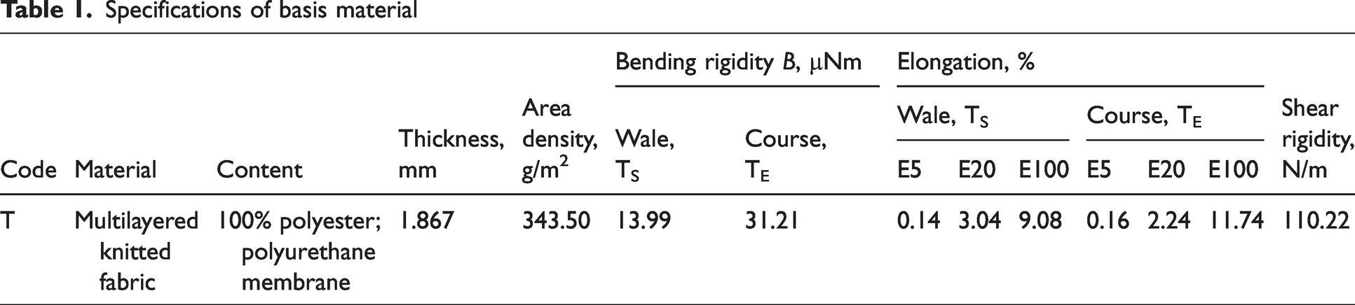
Each variant of the element geometry was prepared in accordance with the following settings: the mesh of a whole garment was 10 mm; the mesh of a conductive element was 5 mm; and the mesh of an element sewing line was 2.5 mm (Figure 1). Modaris (CAD Lectra) software uses particle-based systems to represent the mechanical behavior of the textile material. A finer mesh for conductive elements and sewing lines is required, for a more accurate simulation.
Mesh of element (Variant 1) and tightly fitting garment: (a) static position; (b) dynamic position.
Comfort evaluation parameters
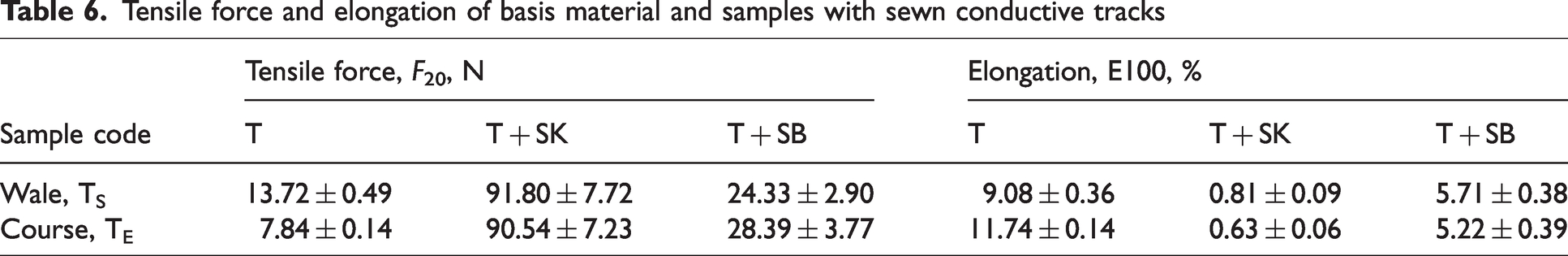
First, the garment was tried on a virtual mannequin in a static position; then a dynamic position, in which the arms were lifted forward, was applied (Figure 1). After virtual trying on, stretching deformations (lengthening, %) were measured along three lines: (1) at the shoulder blades; (2) at the location of the horizontal element along the entire length of the pattern; and (3) only at the horizontal element line (Figure 2). Where there were two elements (Variants 3 and 4), the third measurement line was on one of the two elements.
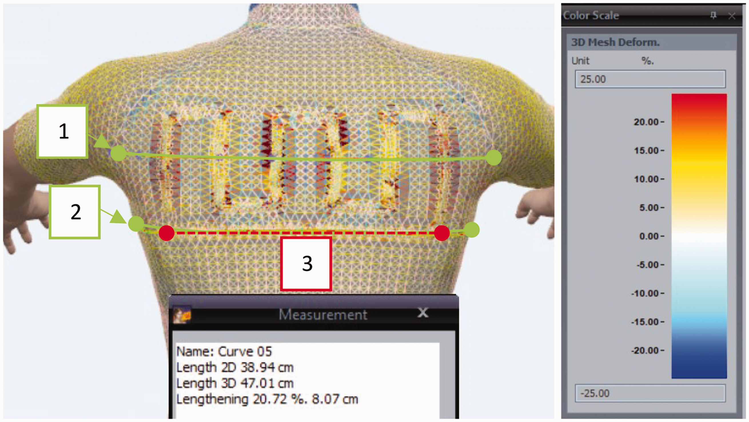
Stretching deformation map in tight-fit garment with color scale and location of lengthening measurement lines in the garment.
The lengthening (%) represents the stretch of a garment measuring line in the 2D pattern (length 2D, cm), after adoption of the dynamic position in the 3D garment (length 3D, cm); it is calculated as

Images of the distribution of 3D garment stretching deformations were also obtained to analyze the research results. The threshold value of the color scale of the stretching deformation map was set to be the same in all cases—25%—to compare images using different conductive elements in the dynamic posture.
The first measurement line contains different widths of conductive material: in Variant 1, it is 6 cm in total; in Variant 2, it is 10 cm; and in Variants 3 and 4, it is 8 cm. This affects the quality of the garment simulation at the location of the element, the distribution of stretching deformation near the element and the lengthening (%) result, especially if the system is designed using materials with significantly different properties.
Each virtual garment was virtually tried on three times; the lengthening (%) was measured at each of the three measuring lines, and the coefficient of variation, v, as well as the absolute error, Δ, was calculated. The coefficient of variation v did not exceed 4.48%.
Results and discussions
Description of the samples with conductive tracks
Using cut-and-sew technology, conductive tracks were created using two kinds of conductive material—knitted SB and woven SK (Table 2). The electrical resistance of the created systems (Table 4) was estimated according to EN 16812:2016 using a Keithley 2614B SourCeMeter multimeter. 58 The procedure is described in more detail in a previous article. 18
Electrical properties of samples with sewn conductive tape
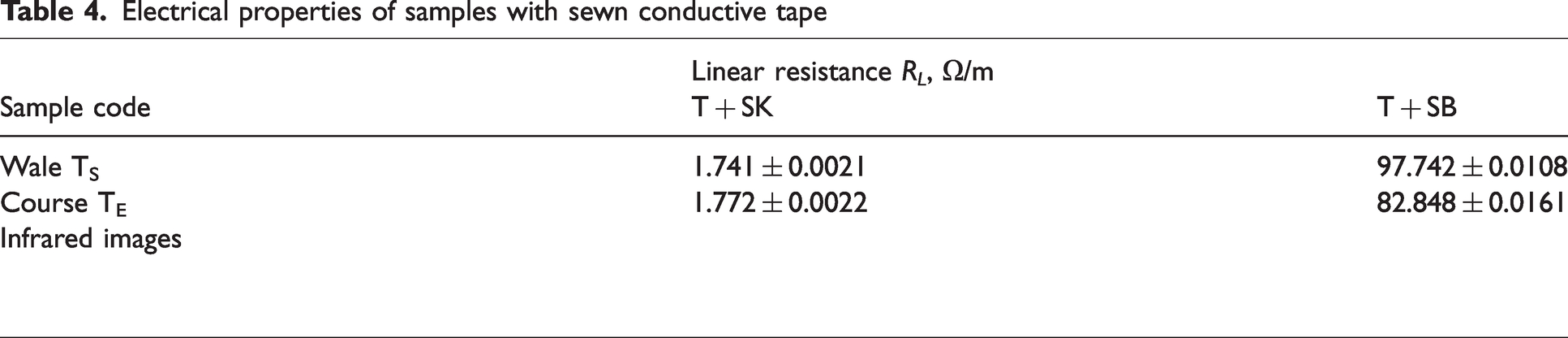
As the conductive material chosen for the 10 mm tape had a different resistivity (Table 1), the measurements of electrical resistance of the created systems showed the same tendency. A higher electrical resistance was estimated for samples with SB than for samples with SK (additionally, 1.741 and 1.772 Ω/m for samples with SK, and 97.742 and 82.848 Ω/m for samples with SB). The heating capability of the samples was demonstrated by taking infrared images with a FLIR camera. Similar temperatures (28°C and 31°C) were obtained at a voltage of 0.5 V for samples with SK tape and at a voltage of 2.5 V for samples with SB tape. The electrical properties of the created structures have been further explored in previous research. 18
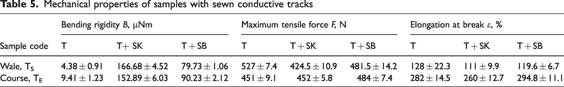
Systems created with conductive tracks were described in terms of mechanical parameters. The parameters of the bending and tension for the basis fabric T and for the samples with sewn conductive tape (T + SK and T + SB) are given in Table 5. Despite the insignificant change in thickness parameter for samples with sewn tracks (h = 1.775 mm for T + SK; h = 1.846 mm for T + SB), the other parameters were different between the samples. Samples with SK show twice the bending rigidity, compared with samples with SB tape, and the estimated flexural rigidity was up to 10 times higher for samples with SB and up to 40 times higher for samples with SK, compared with the basis fabric T. It can be concluded that the systems created with SB knitted conductive fabric showed less flexural rigidity; this fact is essential for a good garment fit and comfort, as discussed later.
Mechanical properties of samples with sewn conductive tracks
As can be seen from Figure 3, there is a significant difference in the tensile behavior of the materials chosen for the conductive lines. Created systems with conductive tracks retain a high level of maximum force and elongation, and the estimated values of the parameters are similar to the properties of the basis material (Table 5). However, the results for the bending rigidity suggest that the aesthetics and comfort of the garment can change significantly when using systems with conductive tracks. It is assumed that the conductive tracks displaced on the surface of textile fabric can change the appearance of garment parts; therefore, it is important to carefully choose the right design and position of integrated electrical conductive circuits or heating elements, as well as the appropriate joining technology. This is further explored in a virtual simulation of a prototype garment with a sewn conductive textile element.
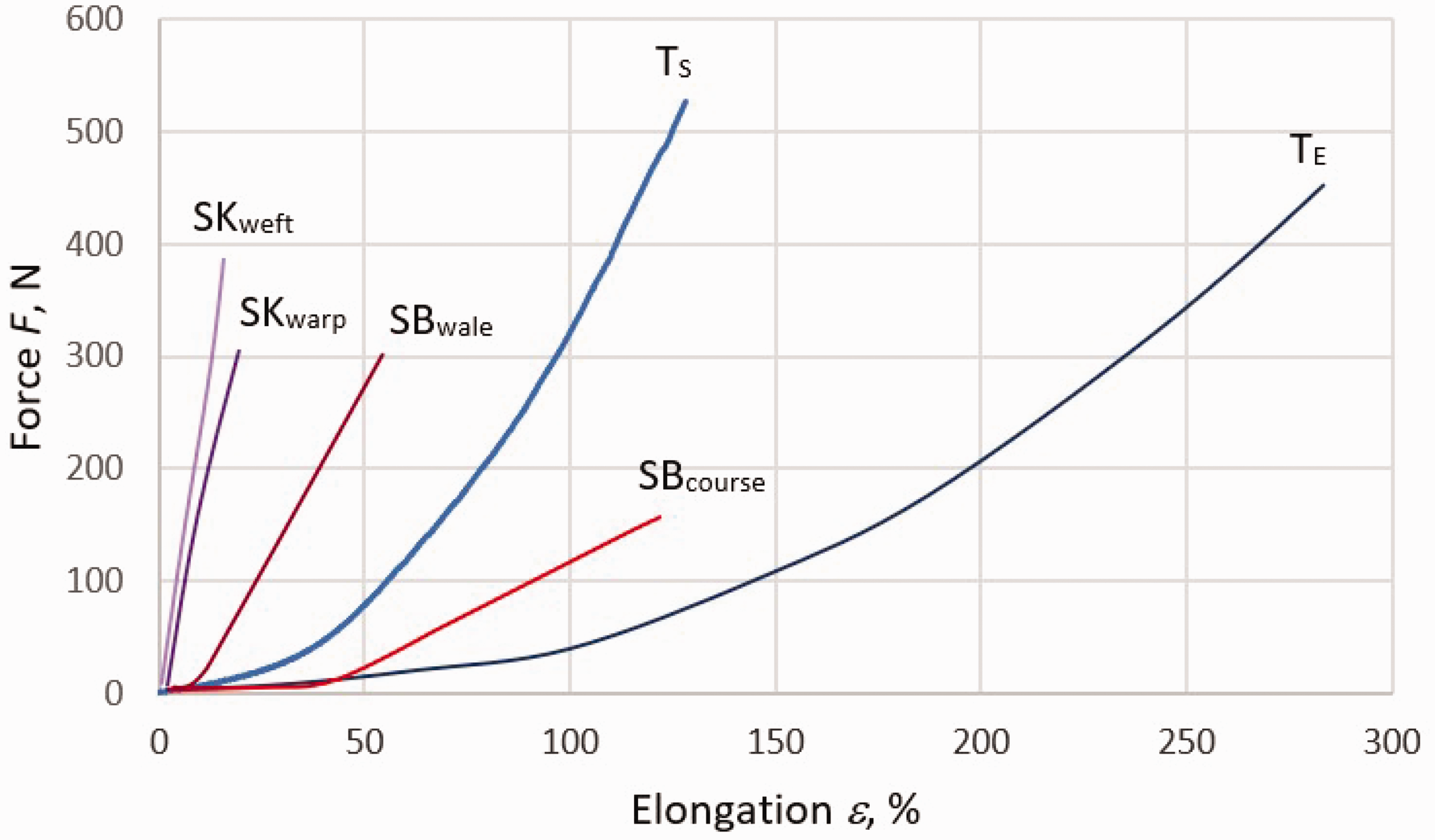
Typical tensile curves of materials chosen for the investigations.
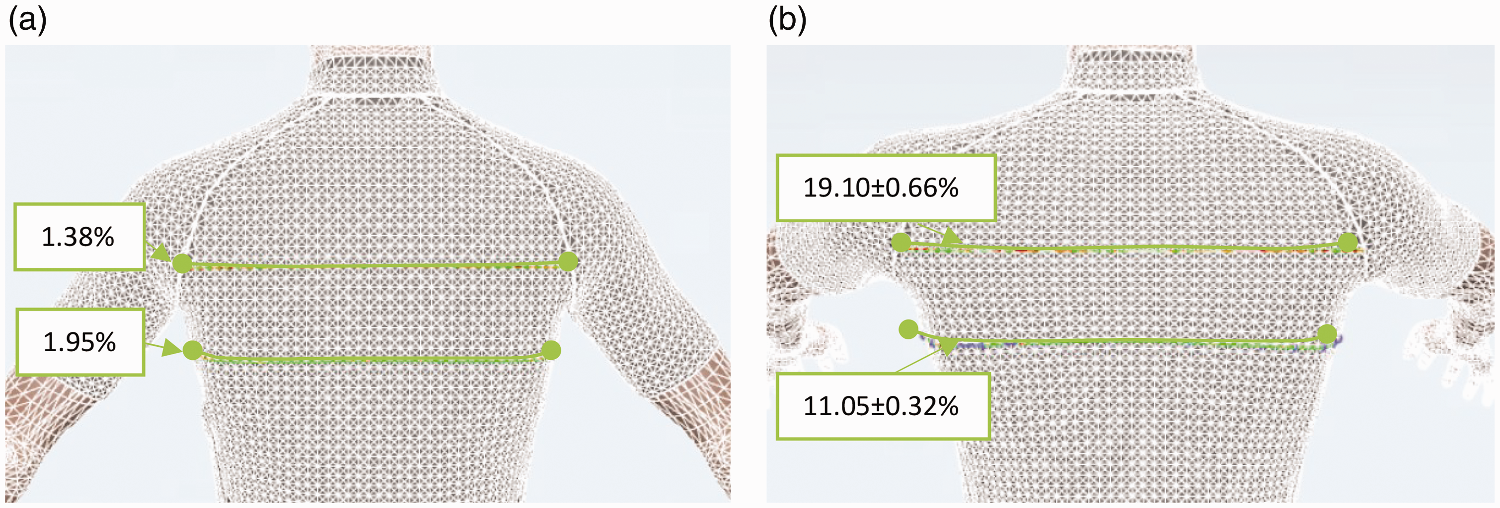
The deformation behavior of the textile material and its systems at small loads is of great importance for the garment design and virtual simulation. Small loads simulate the level of deformations that textile materials are likely to undergo during garment manufacture and wear. 55 Table 6 gives a comparison of the force, F20, required to deform the specimens to 20% elongation. In addition, the elongation E100 of developed systems was estimated at 4.9 N, as is required by the FAST methodology. 55
Tensile force and elongation of basis material and samples with sewn conductive tracks
The analysis of tensile force F20 (Table 6) revealed that up to 3.8 times less force is required to obtain 20% deformations for the system with SB conductive tracks (28.39 N for TE + SB; 24.33 N for TS + SB), compared with the system with SK tracks (90.54 N for TE + SK; 91.80 N for TS + SK). It was proven that sewn conductive tracks limit the deformability of the basis material T at small loads. A smaller elongation was recorded at 4.9 N for sample TE + SB, up to 2.2 times, and 18.6 times for sample TE + SK (correspondingly, 0.62 times for TS + SB and 11.2 times for sample TS + SK). These findings are important for the selection of conductive tracks for the development of smart clothing and have been validated during simulation of virtual garments with conductive textile tracks adapted to the geometry of an element with a heating function.
Virtual garment analysis
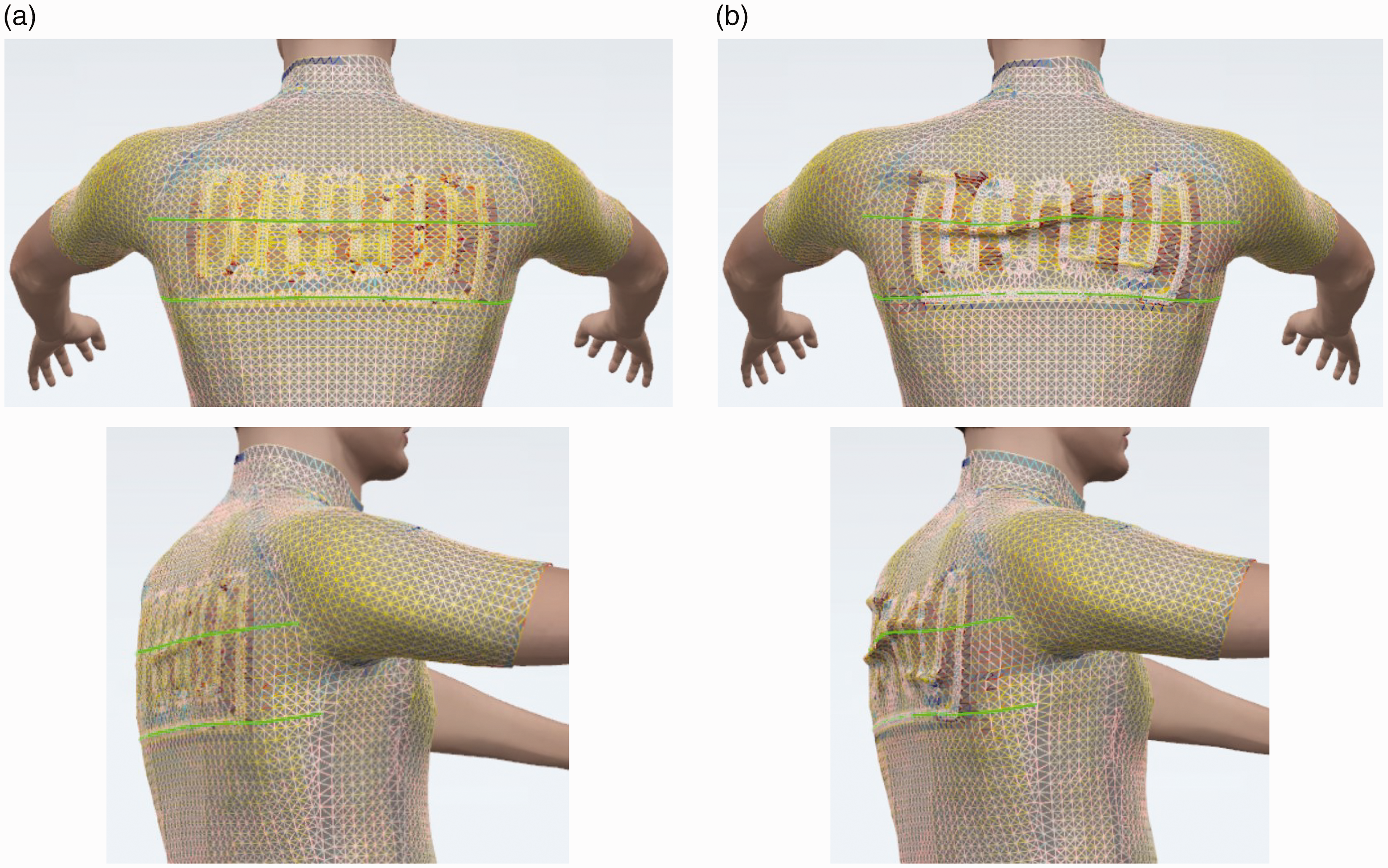
Simulation of the virtual garment revealed that, during the dynamic arm lifting motion, the lengthening in Measurement lines 1 and 2 increased by 13.8 times at the shoulder blade line and up to 5.7 times at 5 cm below the sleeve opening (Figure 4). When the body moves, the back of the garment is stretched the most in the shoulder blade area. Horizontal tracks of conductive fabric in this line should be avoided to maintain the best comfort of the garment, as conductive elements reduce the deformability of the basis material. As can be seen from Table 6, the deformation behavior of the system with sewn SK tape is significantly worse than that with the SB tape; thus, the use of SB for the element with conductive tracks will provide better wearing comfort during body movement.
Lengthening (%) in garment without conductive element: (a) static posture and (b) dynamic posture.
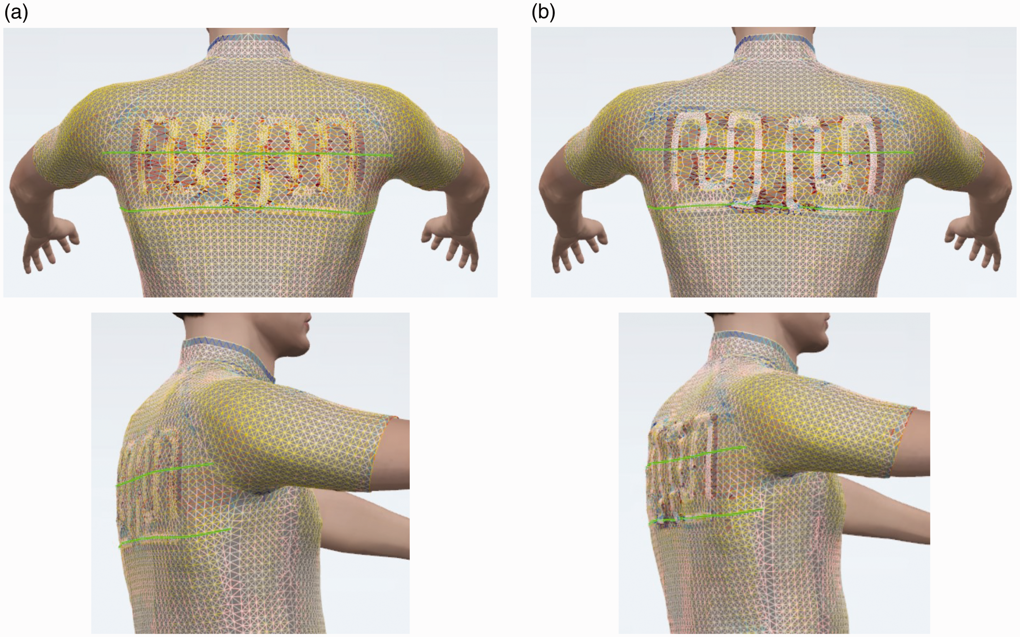
Analyzing the influence of the conductive element variants (Table 7, Figures 5 to 8), it was observed that, the closer the tracks of conductive material are to each other (Variant 2: distance between vertical tracks, 20 mm), the more restricted are the stretching deformations of the garment in the transverse direction when the hands are lifted. Even after dividing the elements into two groups and spacing them 80 mm apart (Variant 4), very close tracks of conductive material limit the deformability, and the lengthening result in Line 1 is very similar as for the case of Variant 2. Better stretching deformation properties are obtained when the two elements are separated by a smaller gap (Variant 3, 32 mm), so the distance between the tracks is larger (28 mm). The best stretching deformation properties during dynamic movement are determined in the case of Variant 1, when the SB conductive material extends 6 cm along the measuring line, and the vertical tracks are separated by the maximum distance (44 mm). It should be noted that the deformability of Variants 1 and 3 in Measuring line 1 varies within the error limits, so when using SB conductive material, analogous properties are obtained both with one larger element (Variant 1) and with two separate ones (Variant 3). However, this is not the case for SK conductive material; in this case, better deformability was achieved using two elements (Variant 3).
Stretching deformations (lengthening, %) using different conductive materials and different element geometries
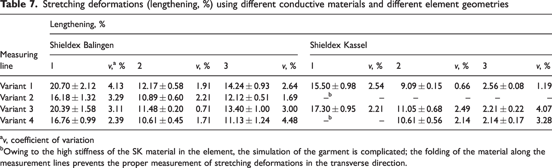
v, coefficient of variation
Owing to the high stiffness of the SK material in the element, the simulation of the garment is complicated; the folding of the material along the measurement lines prevents the proper measurement of stretching deformations in the transverse direction.
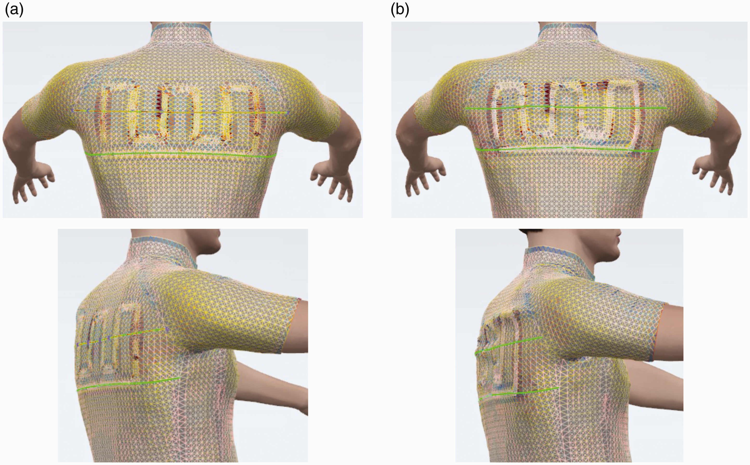
Strain maps for conductive materials in Variant 1: (a) Shieldex Balingen and (b) Shieldex Kassel.
Strain maps for conductive materials in Variant 2: (a) Shieldex Balingen and (b) Shieldex Kassel.
Strain maps for conductive materials in Variant 3: (a) Shieldex Balingen and (b) Shieldex Kassel.
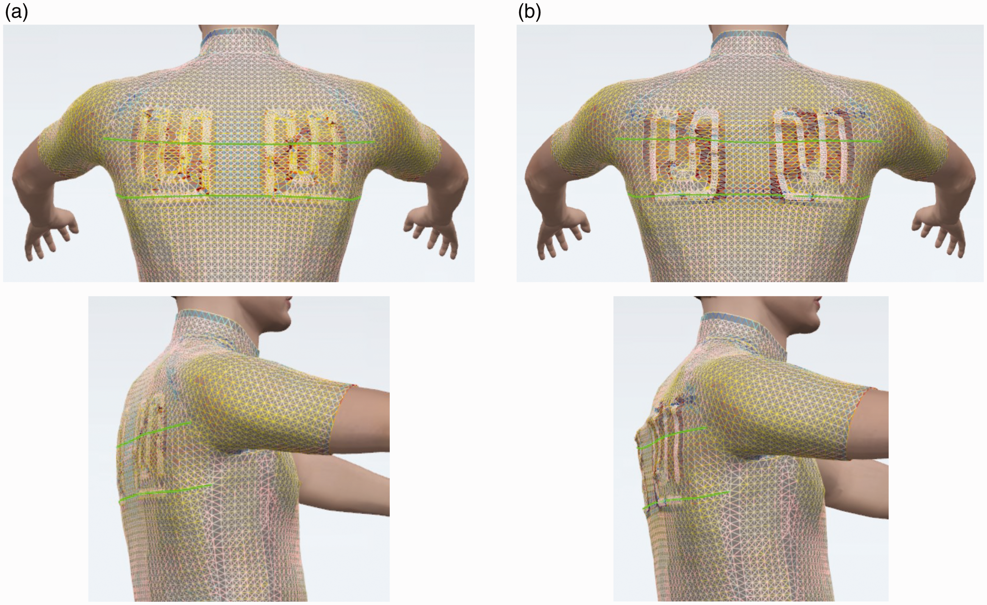
Strain maps for conductive materials in Variant 4: (a) Shieldex Balingen and (b) Shieldex Kassel.
The second measuring line consists of a horizontal track of conductive fabric and short sections of the basis material on the sides; along this line, the deformability of the garment in the transverse direction is mostly restricted by the sewn track of conductive material. There is no significant difference between Variants 1 and 2, since the track is of the same length. Splitting into two elements that are separated from each other by 32 mm (Variant 3) or 80 mm (Variant 4) did not show the expected improvement in deformability; lengthening (%) values were small and very close to that observed for Variant 2. It is believed that this is influenced by the number of vertically configured tracks near the horizontal long track, because the distance is small enough (20 mm) that the deformation is restricted not only by the continuous horizontal track, but also by the horizontal parts of the configured tracks (in the case of Variant 2, it is 16 cm).
The lengthening along the third measurement line, that is, only along the part of the horizontal track, is related to the tensile elongation of the material systems in the transverse (course) direction at a tensile force of 4.9 N (Table 6). Using SB, the elongation is 8.2 times higher than using SK. In the virtual garment, lengthening (%) with SB along the third measurement line is 5.6 times higher than with SK. However, even when using the same conductive material (SB), but different variants of the conductive material element in the virtual garment, the lengthening (%) along the horizontal track line is different, and depends on the geometry of the element and the density of the configured tracks. The best stretching deformation properties in the transverse direction of the system were shown by Variant 1, for which the element is the widest; that is, the tracks are placed at the greatest distance from each other, so their horizontal parts do not significantly affect the deformation of the adjacent continuous track. Variant 3 with SB shows similar results to Variant 1 because the lengthening (%) varies within the error limits. The same could be stated about Variants 2 and 4 with SB.
With the conductive material SK, it was difficult to run the simulations for Variant 2 and, partly, Variant 4 (Table 7), because SK is characterized by extremely high bending rigidity and extremely low values of tensile elongation in both directions (Table 2); this affects the quality of the simulation and the stretching deformation of the system, since the tracks of conductive material strongly limit the deformability of the basis material (Table 1) in both directions. In Variant 2, the vertical tracks of the conductive element are very close to each other; therefore, the influence of the low tensile elongation and high bending rigidity of SK is significant and this causes complications, in rendering, and measurement of the lengthening is pointless (Figures 6 and 8).
Analyzing SB and SK in Variant 1, it can be seen that lengthening in Measuring line 1 with SK is 1.3 times lower than that with SB. In Measurement line 2, the influence is the same, while the most obvious difference between the conductive materials used can be seen in Measurement line 3. Lengthening with SK is 5.6 times lower than with SB in place of the horizontal element. In the case of Variants 3 and 4, an analogous result was obtained at the location of Measuring line 3, where SK, owing to the low deformability, greatly limits (5–6 times) the stretching deformations of the system in the transverse direction for the dynamic lifting movement of the hands.
A comparison of the lengthening parameter for the virtual garment with the element (Table 7) and that without the element (Figure 4) shows that Variants 1 and 3 with SB conductive tracks on the shoulder blade line (1) do not have a significant effect on the deformation of the garment in the transverse direction, since the values for Line 1 vary within the error limits. Conversely, owing to the close proximity (20 mm) of the SB vertical tracks, garment stretching in the transverse direction is inhibited by 2.3%–2.9% for Variants 2 and 4. The elements produced by knitted SB conductive fabric proved to be more deformable when the body moved; this is essential for improving the fit and comfort of smart clothing. The strain maps of the virtual prototype presented in Figures 5 to 8 demonstrate not only the improved comfort but also the higher aesthetic appearance of the garment with the integrated element with conductive tracks of knitted SB fabric.
Conclusions and recommendations
The study proves that conductive tracks can be designed using cut-and-sew technology, and the system deformation at wear loads depends on the type of conductive fabric used. The sewn conductive tracks restrict the deformability of the basis material at low loads; up to four times less force is required to obtain 20% deformations for the system with conductive tracks of SB, compared with the system with SK.
Smart clothing virtual prototyping is an excellent technique to assess the design features of a garment and to evaluate the feasibility of incorporating an electrical circuit, based on the use of conductive fabric with minimal changes to the fit and comfort of the garment. The geometry of the element with conductive tracks is important for wear comfort of the garment during body movement. The simulation showed that the highest deformations, of up to 20% lengthening, could occur in the shoulder blade area, and that horizontal tracks of conductive fabric should be avoided to maintain the garment comfort, as sewn conductive elements reduce the deformability of the basis material by up to 18.6 times at a force of 4.9 N. However, even when using the same conductive material but different element geometries in the virtual garment, lengthening (%) in the horizontal track line is different, and depends on the density of the configured vertical tracks. The best stretching deformation properties in the created element with conductive material tracks were obtained for Variant 1, with the conductive material SB extending 6 cm along the measuring line, and the vertical tracks placed at a maximum distance of 44 mm.
Virtual prototyping helps to assess not only deformability and garment comfort, but also the aesthetic appearance of the garment in motion. The study shows that the element with conductive tracks will be severely deformed by movement. To avoid the damage of conductive tracks and to ensure the comfort of the garment in motion, it is important to choose a conductive fabric and a joining technology that has the smallest influence on the behavior of the produced system. It was estimated that deformation of the element with sewn SK tape is significantly worse than that with the SB tape, thus, the use of SB for the element with conductive tracks will provide better wearing comfort. Conductive knitted fabric SB is an excellent choice, which secures good electrical and excellent deformation properties when designing tightly fitting smart clothing. However, the durability and resistance to cycle stretching and, in particular, to washing must be assessed for the element with conductive fabric tracks. The development of such elements should be further investigated.
Conductive fabrics are sensitive to intensive wear and, in particular, to garment washing, so further development of the selection needs to take into account the care conditions necessary for smart clothing. Adhesive bonding and seam insulation technologies18,59 could be applied to secure reliable electrical circuits. However, the use of any additional layer stiffens the element with conductive material and reduces its ability to stretch, which is necessary for active wear.
The results of this study should not be estimated as exhaustive recommendations for the development of smart clothing with heating functions. The results of the research support the specificities and potential of developing smart clothing using virtual prototyping and cut-and-sew technologies.
Footnotes
Declaration of conflicting interests
The author(s) declared no potential conflicts of interest with respect to the research, authorship, and/or publication of this article.
Funding
The author(s) received no financial support for the research, authorship, and/or publication of this article.