
Abstract
Textiles incorporating phase change material have attracted increasing attention due to their temperature regulating function. Although a great progress has been made in the development of phase change material textiles, it has been found that the loading amount of phase change materials is limited by other final properties. Recently, we have proposed a sandwich fibrous phase change material encapsulation with a relatively high phase change material loading amount, which is a multi-layer fabric structure containing phase change material. However, the breathability of sandwich fibrous phase change material encapsulation should be improved because there is no path for air to penetrate through. In this work, the sandwich fibrous phase change material encapsulation structure with polyethylene glycol as phase change material is modified by introducing different air pockets in the thermal function layer ranging from 19% to 64%. The leakage phenomenon, phase transition behavior, thermal energy storage, breathability, T-history and practicality of the breathable sandwich fibrous phase change material encapsulations are investigated. As a result, the maximum polyethylene glycol loading amount of the phase change materials pocket is 83 wt%, and there is no leakage of polyethylene glycol during working time. The overall enthalpy value of the breathable sandwich fibrous phase change material encapsulation ranges from 27 J/g to 48 J/g. The optimal air permeability and water vapor resistance of the breathable sandwich fibrous phase change material encapsulation is 9 mm/s under 100 Pa and 34.5 m2 Pa W−1. Furthermore, the heterogeneous heat transfer through the breathable sandwich fibrous phase change material encapsulation is found due to the complicated thermal resistances of the hybrid thermal functional layer. In addition, for breathable sandwich fibrous phase change material encapsulation, the flexibility, hydrophobicity, self-cleaning property, abrasion resistance, and stability after water immersion are found. We believe the research has a great potential in various applications related to phase change material.
Personal temperature management (PTM) has gained increasing attention in recent years.1 –4 Phase change material (PCM) has been studied as an alternative to achieve PTM.5 –7 The working principle of PCM is that the temperature of PCMs can be maintained within a particular range, while thermal energy can be stored or released, depending on the difference between the temperature of the PCM and the surrounding temperature.8 –11 The PCM with solid-liquid phase transition is usually used for PTM, while the control of the liquid PCM or PCM in a stable phase transition state is challenging without proper storage materials.
To prevent leakage of PCM for enhanced thermal stability, it is necessary to employ supporting materials to encapsulate the PCM. Three strategies have been proposed based on this principle: microencapsulation phase change material (MPCM),12,13 solid–solid phase change material (SSPCM), 14 and form-stable phase change material (FSPCM).15 –17 MPCM comprises a shell-core structure, in which the shell is made of materials with high thermal stability, while the core consists of PCMs.18,19 The PCM is fully within the shell structure, and leakage can be entirely avoided. However, it has been reported that the encapsulation efficiency of the MPCM could be enhanced. In addition, the mechanical properties of MPCMs depend on the shell, and unexpected shell failure during application may lead to MPCM leakage. SSPCM is a type of composite comprising a solid part and a soft part, 20 and exhibits high thermal stability in the solid part, while the soft part consists of PCMs. At their operational temperature, the soft part becomes mobile, allowing for thermal energy storage. However, SSPCM exhibits limited thermal energy storage and alters the phase transition of SSPCM when compared with pure PCM. This is attributed to restricted molecular movement of the soft part comprising PCM molecules during their working temperatures. FSPCM is usually a composite group consisting of porous materials as supporting elements to contain PCM. 21 During their working temperature, melting PCM is confined in porous materials due to capillary force. However, the thermal energy storage and phase transition of FSPCM are restricted due to the impact of pores (e.g. pore type, pore size, etc.) on the macromolecular movement of PCM.17,22,23 While present PCM has their own pros and cons in terms of leakage prevention, the appropriate PCM for each application should be considered. Nevertheless, resolving the issue of leakage alone is insufficient for achieving PTM.
The use of PCM in textiles can be categorized into two types: PCM fibers24 –27 and PCM fabrics.28 –31 There are various methods of producing PCM fibers, such as melting spinning, solution, electrospinning, centrifugal spinning, interfacial polyelectrolyte complex spinning, and so on.32 –35 A higher PCM loading amount in PCM fibers supports higher thermal energy storage of PCM fibers, while reducing the mechanical property. 8 For PCM fabrics, the binders are required in fabrics to affix PCMs (e.g. MPCM or FSPCM). However, the use of binders alters the surface chemistry of PCM fabrics. In addition, there is the possibility of MPCM loss or FSPCM loss because of external mechanical movement (e.g. washing, abrasion etc.). 36 Therefore, it can be concluded that the limited amount of PCM and confinement of PCM in PCM textiles are two significant factors that contribute to a decreased thermal energy storage and a change in the phase transition of PCM textiles. In addition, it is crucial to protect PCMs in textiles from sudden mechanical movement for extended usage cycles.
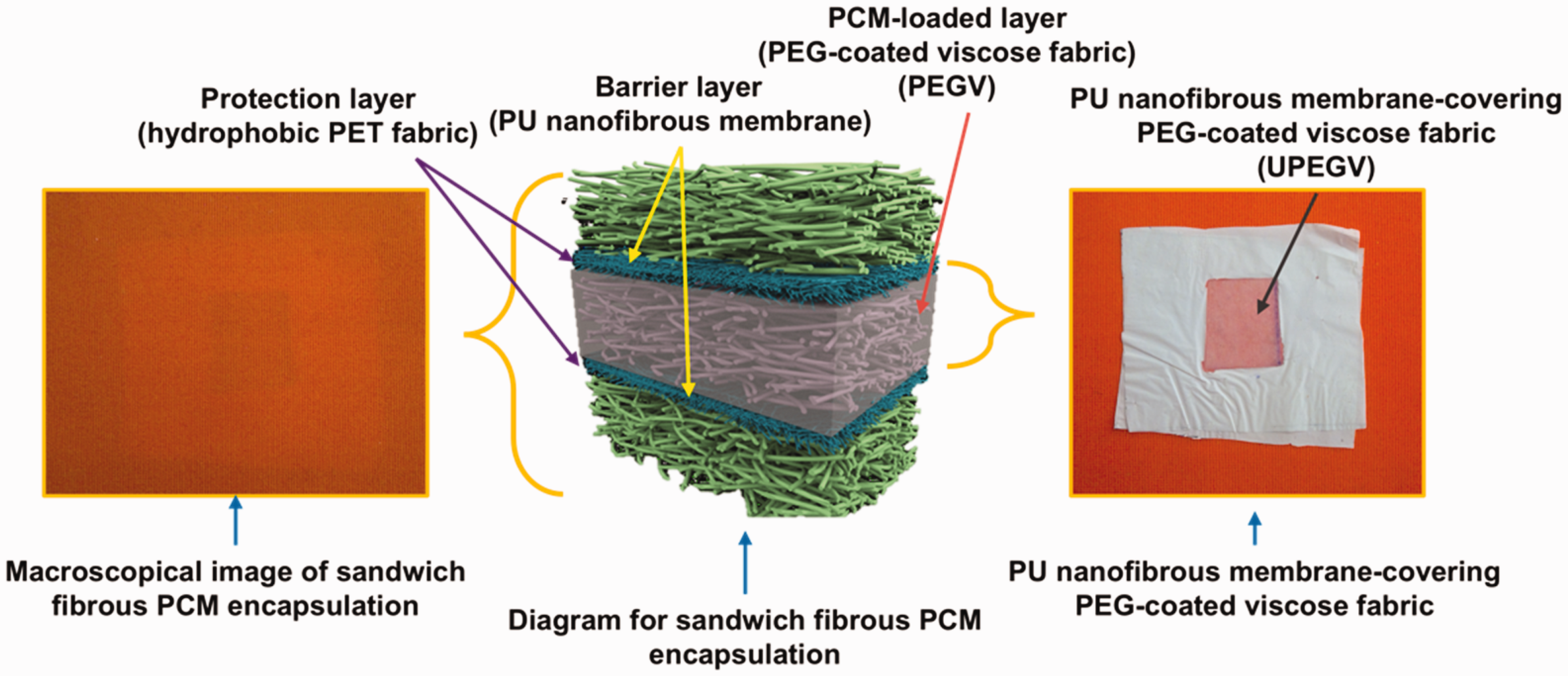
To avoid the disadvantages of present PCM-incorporated fabric, we have successfully proposed a sandwich fibrous phase change material encapsulation (SFPE).37,38 The SFPE is a multi-layer PCM fabric, which consists of a protection layer, barrier layer, and PCM-loaded layer. The paraffin wax and polyethylene glycol (PEG) have been used as PCM in SFPE. By comparing with other present PCM-incorporated fabric, a relatively high PCM loading amount and high enthalpy storage are found in the SFPE. Besides, the SFPE has a good compatibility with fabrics or other products. Although there are various advantages of SFPE, there is no breathability because the PCM-loaded layer is a composite in which there is no path for air or water vapor to penetrate. For the multi-layer fabric-based system, the introduction of air pockets is an alternative to enhance mass transfer and incorporate other materials for functions. 39 For example, US patent 9062913 B2 reported a design of breathable PCM fabric, in which the breathable fabric was as a substrate for the uniform disposition of PCM elements. 40 In addition, Zhang et al. designed a PCM-incorporated mask by introducting an air pocket channel. 41 The thermal therapy of the air pocket-incorporated PCM mask for the allergic rhinitis lasted almost 30 min.
In this work, we follow the previous research work by constructing the SFPE. 38 For a better understanding, the SFPE structure is given in Appendix 1. The polyester (PET) fabric with hydrophobic coating is used as the protection layer, polyurethane (PU) nanofibrous membrane is used as the barrier layer, and PEG-coated viscose fabric is used as the PCM-loaded layer. Better to reveal the thermal buffering effect, PEG with molecular weight (Mw) of 6000 having a melting point of 60°C is used as the PCM in the SFPE. To realize breathability, the PCM-loaded layer is split into air pockets and PCM pockets (PEG-coated viscose fabric). The PCM pockets are uniformly distributed between two barrier layers with certain air gaps. The area consisting of air gaps is labeled as the air pocket. By adjusting the length of the air gap, different breathable SFPEs are obtained. Breathability and the thermal buffering effect of breathable SFPE are investigated. In addition, the flexibility, hydrophobicity, self-cleaning property, abrasion resistance, and stability after water immersion of the breathable SFPE are investigated. Last but not least, the possibility of the breathable SFPE being incorporated into commercial fabric, and the comparison of our work with other reported PCM textiles are discussed.
Experimental section
Materials
PEG (Mw = 6000) was purchased from Sigma Aldrich. Three fibrous materials were used, including polyester (PET) fabric with hydrophobic coating (here labeled as hydrophobic PET fabric), polyurethane (PU) nanofibrous membrane, and viscose nonwoven fabric. The hydrophobic PET fabric was provided by INOTEX Company (Czech Republic), and PU nanofibrous membrane and viscose nonwoven fabric were provided by Department of Material Engineering, Faculty of Textile Engineering, Technical University of Liberec. The details (e.g. morphology and diameter of fiber) of used fibrous materials are included in previous publications.36,37,42 For a better understanding, some details are given in Appendix 2. Here, only the thickness (L), areal density (
Details of used fibrous materials (mean value
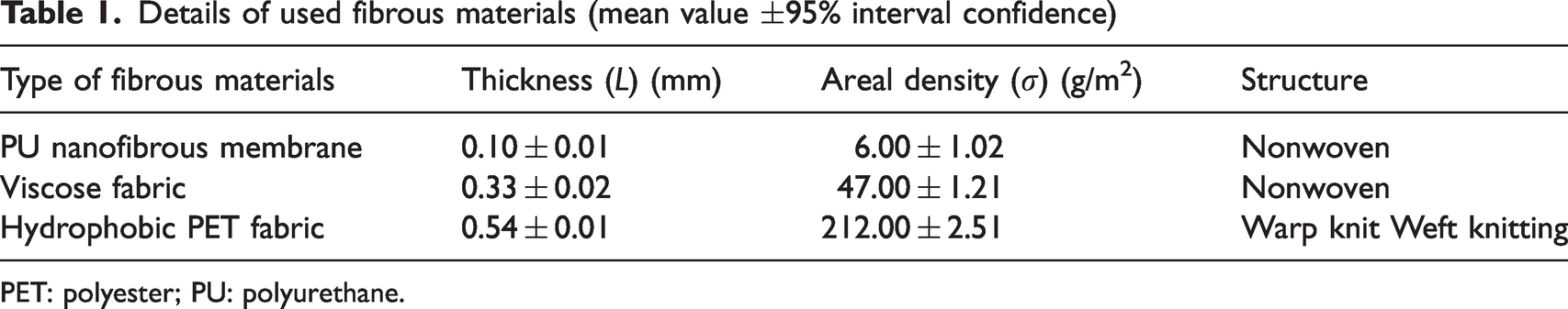
PET: polyester; PU: polyurethane.
Preparation of PEG-coated viscose fabrics
The PEG-coated viscose fabrics were prepared by the melting-coating method according to our previous work. 42 Different mass ratios (RPEG) of PEG to viscose fabric were considered, including 10:1, 9:1, 8:1, 7:1, 6:1, 5:1, and 4:1. The PEG-coated viscose fabrics were labeled as PEGVn-1, where n is the mass ratio of PEG to viscose fabric.
In addition, the melting PEG is adsorbed by PU nanofibrous membrane according to our previous work,37,38 and PU nanofibrous membrane-covering polyethylene glycol-coated viscose (UPEGV) fabrics should be considered for the following measurements. Then, the UPEGVn-1 was labeled, and n is the mass ratio of PEG to viscose fabric.
Preparation of the breathable SFPE
The fundamental configuration of the breathable SFPE is presented in Figure 1(a1) and (a2). The SFPE comprises a protective layer, a barrier layer, and a PCM-loaded layer. The protective layer is a hydrophobic PET fabric, the barrier layer is a PU nanofibrous membrane, and the PCM-loaded layer is where the PCM pockets (PEG-coated viscose fabric) are uniformly dispersed between two barrier layers, leaving specific air gaps. The sealing tape (ST104, BEMIS) is employed to fix all the layers.
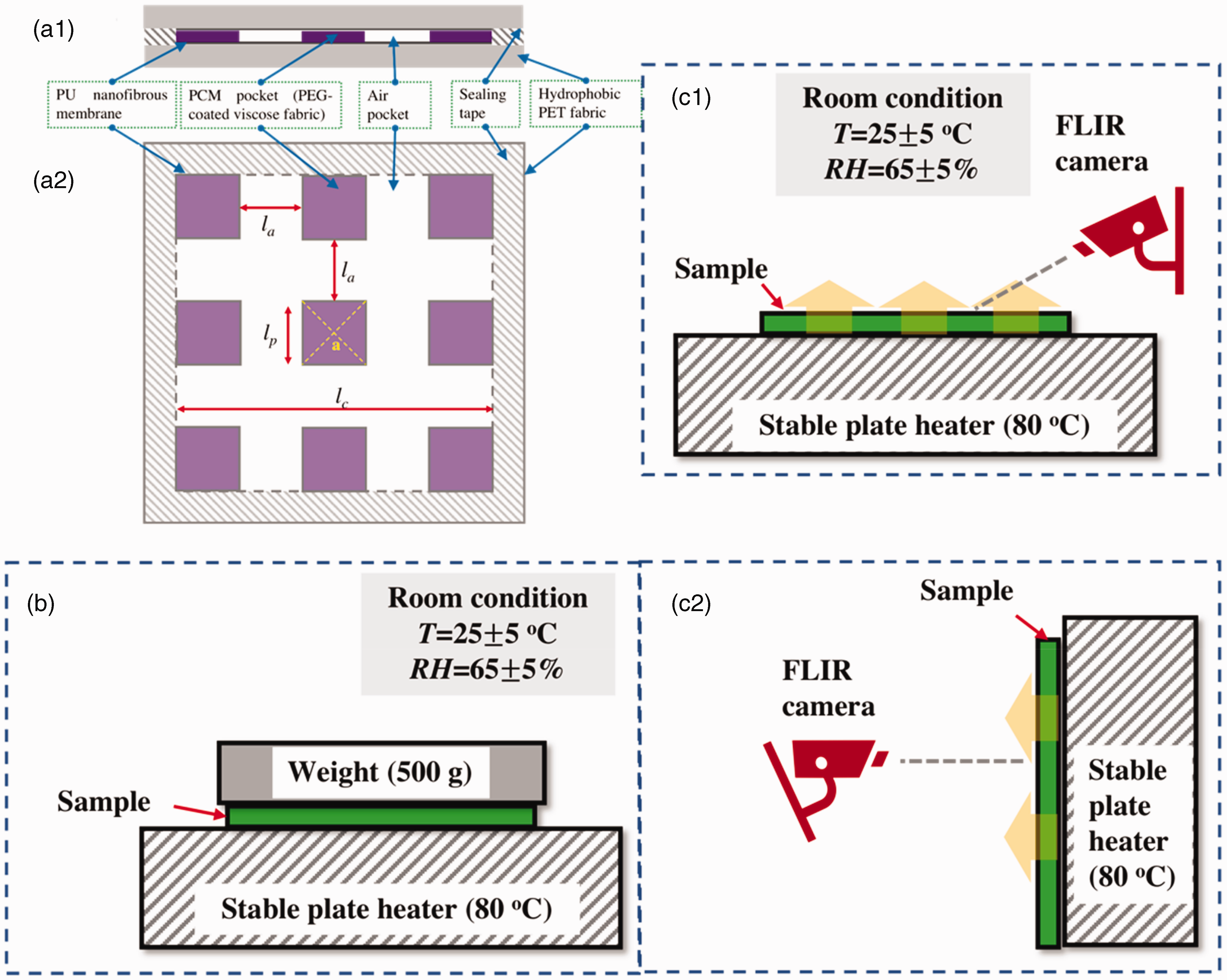
Schematic diagram for the breathable sandwich fibrous phase change material encapsulation (SFPE) and leakage measurement: (a1) cross-section, and (a2) distribution of phase change material (PCM) pockets and air pockets; leakage test for polyethylene glycol (PEG) diffusion along the fabric surface (b); T-history measurement with leakage test along the cross-section direction (c1), and leakage test along the fabric surface direction (c2). Point a in (a2) is the selected point for the measurement of air permeability and water vapor permeability in the following sections.
In detail, nine square PCM pockets are uniformly distributed between two barrier layers. By adjusting the width of the PCM pockets, the different samples are obtained. In detail, 


Description of the breathable SFPE
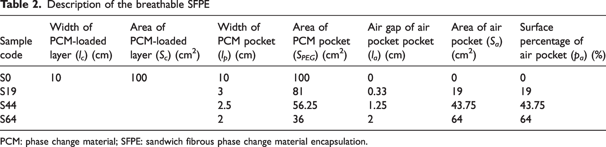
PCM: phase change material; SFPE: sandwich fibrous phase change material encapsulation.
In addition, the PEG-coated viscose fabrics with different PEG loading amounts were prepared as PCM pockets according to previous work, 38 and the mass ratio of PEG to viscose fabric ranged from 5:1 to 10:1.
Tests and methods
Characterization of PEG diffusion inside SFPE after heating/cooling cycles
As shown in Figure 1(b), The sample was placed on the plate heater with a temperature of 80°C, and 500 g weight was placed on the surface of the sample. After 10 min, the samples were taken out and the PCM-loaded layer (consisting of PCM pocket and air pocket) were recorded with an optical camera.
Characterization of leakage phenomena of breathable SFPE after heating/cooling cycles
A custom set-up containing a stable plate heater and infrared camera (FLIR E6) was constructed for the leakage test of the breathable SFPE. As there are air pockets and PCM pockets of the breathable SFPE, two possible leakage phenomena are taken into consideration. The first one is the diffusion of PEG, which is confirmed by observing the interface between the air pocket and PCM pocket. The second one is the penetration of PEG through thickness, which is confirmed by observing whether there is PEG out of the protection layer or not. So, two placement positions of samples are taken into consideration.
Leakage along fabric thickness
As shown in Figure 1(c1), the samples were placed on the stable heater at 80°C for 10 min. Then, the leakage phenomena of the samples were recorded with a forward-looking infrared (FLIR) image and optical images.
Leakage along fabric surface
As shown in Figure 1(c2), the samples were vertically placed on the stable heater at 80°C for 10 min. Then, the leakage phenomena of the samples were recorded with a FLIR image and optical images.
Characterization of leakage phenomena of the breathable SFPE after water immersion
As the protection layer of the breathable SFPE is hydrophobic, there is a self-cleaning property. Instead of a standard washing process and hand washing process, the effect of water penetration into the breathable SFPE is evaluated by totally immersing the sample in water, which is shown in Figure 2(a1). Rather than the prepared breathable SFPE samples with full structure, a mini sample with similar structure in the form of a square is used and shown in Figure 2(a2). Inside the mini sample, the PCM pocket (PEG-coated viscose fabric) locating in the center of sample has a width of 3 cm, while the barrier layer and protection layer have a width of 5 cm. The air pocket is formed at the edges. Then, the commercial binder is used to fix all the layers together.
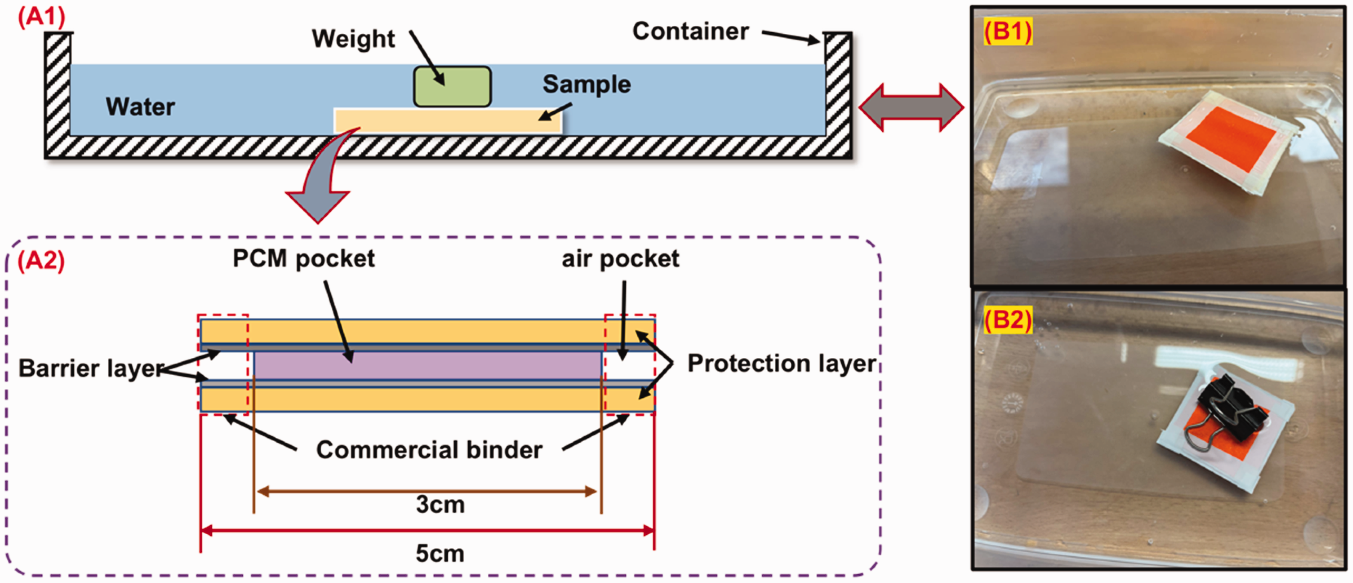
Diagram of immersion of the sample in water: (a1) schematic diagram of set-up; (a2) schematic diagram of mini sample; (b1) floating of mini sample on the water; and (b2) immersion of mini sample in the water by the use of a clamp.
When the mini sample is put in the water, the mini sample will be floating in the water and cannot be immersed in the water, which is shown in Figure 2(b1). It is caused by the hydrophobicity of the mini sample. Then, a weight (e.g. clamp) is put on the mini sample to sink it totally, which is shown in Figure 2(b2). After 2 h, the mini sample is taken out and put in the ambient environment to be dried for 24 h.
To reveal the leakage phenomena of the PEG from the mini sample, the mass of the mini sample before and after immersion were recorded for comparison. In addition, the diffusion of PEG inside the mini sample before and after immersion was recorded by optical camera for comparison.
Characterization of phase transition behavior and thermal energy storage
Differential scanning calorimetry (DSC; Mettler Toledo, USA) was used to characterize the phase transition and thermal energy storage. All the samples with weights from 3 to 10 mg first experienced the thermal history removal by heating from 25°C to 90°C. After heating at 90°C for 5 min, the subsequent cooling process from 90°C to 25°C, and the heating process from 25°C to 90°C were carried out. The nitrogen gas rate was 20 mL/min during the whole DSC measurement. The heating/cooling cycles were repeated 11 times, the first and 11th cooling process and heating process were recorded with a built-in software, respectively.
As a result, the melting/crystallization onset temperature (Tom/Toc) (oC), melting/crystallization peak temperature (Tpm/Tpc) (oC), melting/crystallization endset temperature (Tem/Tec) (oC), and melting/crystallization enthalpy value (
In addition, the overall enthalpy value (

Characterization of breathability
The breathability characterization of the breathable SFPE was evaluated by measuring air permeability and water vapor resistance (Ret). 43
The air permeability of the breathable SFPE was investigated by using the FT3300 tester according to ISO 9063:1991.
44
In detail, the applied pressure values for measurement were set from 60 Pa to 200 Pa with an interval of 10 Pa. Each measurement was repeated five times for each sample and the statistics were obtained. To predict the air permeability, the Forchheimer model was applied and is expressed in equation (9).36,45,46 
The water vapor permeability (WVP) measurement of the breathable SFPE was performed by using the tester PERMETEST (SENSORA, Czech Republic) in line with ISO 11092. After measurement, the water vapor resistance (Ret) (Pa m2/W) was measured following equation (10), where the 
Characterization of T-history
A custom set-up was to measure the T-history of the sample as well as evaluate the leakage test, 38 which is shown in Figure 1(c1). The sample was placed on the plate heater at a temperature of 80°C. Then, the surface temperature change of the sample (Ts) was recorded by using an infrared camera (FLIR E6) with emissivity of 0.9. After the heating process, the sample was immediately transferred on to the surface of the insulation materials at a temperature of 25°C, and the cooling process started. Correspondingly, the Ts values were also recorded during the cooling process until the Ts value reached a stable value.
Characterization of abrasion
The abrasion of the breathable SFPE is essential for practical usage. As the breathable SFPE is the multi-layer fabric structure, only the abrasion behavior of the protection layer (PET fabric with hydrophobic coating) was measured. In detail, the abrasion of PET fabric with a hydrophobic coating was evaluated by way of a Martindale abrasion tester according to ASTM D4966-98. 47 The abrasion time was set at 1000, 2000, 3000, 4000, 5000, 6000, and 7000. The photos of the abrasive surface of the PET fabric with hydrophobic coating were recorded.
Characterization of hydrophobicity
The hydrophobicity of the breathable SFPE is only up to the protection layer (PET fabric with hydrophobic coating), which was confirmed in previous work. 36 To make the hydrophobicity of the breathable SFPE more visual, 1 mL water was squeezed out from the dropper, and the water droplets depositing on the surface of the breathable SFPE were recorded by an optical camera.
By considering the effect of abrasion on the hydrophobicity of PET fabric with hydrophobic coating, 5 µL water was deposited on the surface of the abrasive PET fabrics with hydrophobic coating. After 5 min deposition of the water droplet, the water contact angle (WCA) was recorded. The WCA measurement was performed by using a portable computer-based instrument (see System E Advex Instrument) following ISO 27448:200. Each sample was measured five times to obtain statistics.
Characterization of self-cleaning behavior
The self-cleaning behavior of the breathable SFPE was measured by following previous work. 48 The breathable SFPE was first put at an inclined degree of 30° to the horizontal plane. Then, the Blue II dye powder with a mass of 1 g was placed on the surface of the breathable SFPE. The self-cleaning behavior was examined by dropping water to rush the Blue II dye powder by using a micropipette. The process in which the Blue II dye powders were removed was recorded by an optical camera.
Characterization of flexibility
As the breathable SFPE was not a standard fabric, the flexibility was examined by a squeezing-relaxing cycle by hand. The process was recorded by an optical camera.
Results and discussion
Determination on suitable structure of the breathable SFPE
As the PCM-loaded layer comprises PCM pockets and air pockets, as shown in the Figure 1, the possibility of PEG leakage within the PCM-loaded layer must be considered. There was no PEG leakage observed through the SFPE after heating/cooling cycles, either from the vertical or planar direction. The weak interfacial adhesion between melting PEG and the protection layer and the use of a PU nanofibrous membrane in the SFPE, as explained in Section ‘Introduction’ are responsible for this outcome.
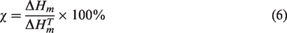
In addition, it was observed that the diffusion of melting PEG within the PCM pocket was strongly linked to the amount of loaded PEG. For instance, Figure 3(a1) displays the leakage phenomena of sample UPEGV10-1, in which the PEG had dispersed throughout the PCM pocket and air pocket, resulting in obvious leakage. However, when the ratio of PEG to viscose fabric was reduced to 5:1, sample UPEGV5-1 exhibited a clear interface between the PCM pocket and air pocket, and little diffusion of melting PEG was detected (Figure 3(a2)). The following reasons are found:
Leakage of phase change material (PCM) pocket of sample polyurethane nanofibrous membrane-covering polyethylene glycol-coated viscose (UPEGV)10-1 (a1) and UPEGV5-1 (a2) after heating/cooling cycles with pressure, and diagram for diffusion of melting polyethylene glycol (PEG) inside breathable sandwich fibrous phase change material encapsulation (SFPE) after heating/cooling cycles with pressure; (b1) and (b2) diffusion of PEG inside UPEGV with low amount of PEG and diffusion of PEG inside UPEGV with high amount of PEG).
When there is a higher loading amount of PEG in the PCM pocket as shown in Figure 3(b2), some PEGs are located outside of the viscose fabric. Before the heating process with pressure, the PCM pocket ideally has a width of D0 and thickness of L0. During the heating process with pressure, the PEG outside of the viscose fabric is forced to move along the fabric surface direction because melting PEG is movable. Then after the heating process with pressure, the dimension of the PCM pocket is changed, and D0 becomes D1 and L0 becomes L1. Consequently, during heating and cooling cycles with pressure, the PEG outside the viscose fabric melts and begins to move along the fabric surface direction, leading to leakage phenomena. For example, the UPEGV10-1 has a PEG diffusion and instability of PEG encapsulation.
When the PEG loading amount is limited as shown in Figure 3(b1), the majority of PEG is efficiently adsorbed by the viscose fabric and PU nanofibrous membrane, despite a very small amount being outside the fabric. It is supposed that the movement of melting PEG inside the viscose fabric and PU nanofibrous membrane is not affected, and dimensions including thickness and length are not significantly changed. After undergoing heating and cooling cycles under pressure, the PEG located outside of the viscose fabric and PU nanofibrous membrane is completely melted, while still remaining within the coverage of the PCM pocket.
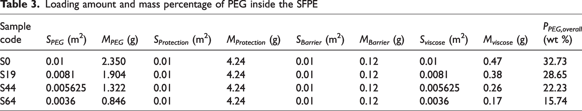
Therefore, the optimal PCM-loaded layer for creating a breathable SFPE PEGV5-1, and the PCM loading amount in the PCM loaded layer reached 83 wt%. Correspondingly, loading amount and mass percentage of PEG inside SFPE are calculated according to equation (7), respectively, and presented in Table 3. The mass percentage PEG inside SFPE (PPEG,overall) ranges from 15.74 wt% to 32.73 wt%. It is known that a higher PCM loading amount supports higher thermal energy storage and the thermal buffering effect. By organizing PCM containing textiles (especially for PCM containing fabrics), the reported MPCM coating layer (including binder, etc.) of MPCM-coated fabrics for personal temperature management ranges from 5 wt% to 30 wt%,36,49 –53 and the reported maximum MPCM coating layer (including binder, etc.) of MPCM-coated fabrics for heat protection or firefighter clothing reaches 45 wt%.54 –56. Thus, the breathable SFPE has a comparable PCM loading amount, whose PCM loading amount is high enough for PTM and even for heat protection.
Loading amount and mass percentage of PEG inside the SFPE
Breathability of air pocket-incorporated SFPE
Figure 4(a1) displays the air permeability values of SFPE samples with air pockets. The air permeability of the SFPE samples with air pockets is between 4.6 and 9 mm/s under 100 Pa. Although it is expected that a higher area of air pocket in the SFPE would result in an increase in air permeability, the air permeability of the SFPE samples does not follow this trend. Furthermore, the air permeability of samples S44, S64, and S19 is determined to be greater than that of the reference sample. Two factors are taken into account in explaining this discrepancy:
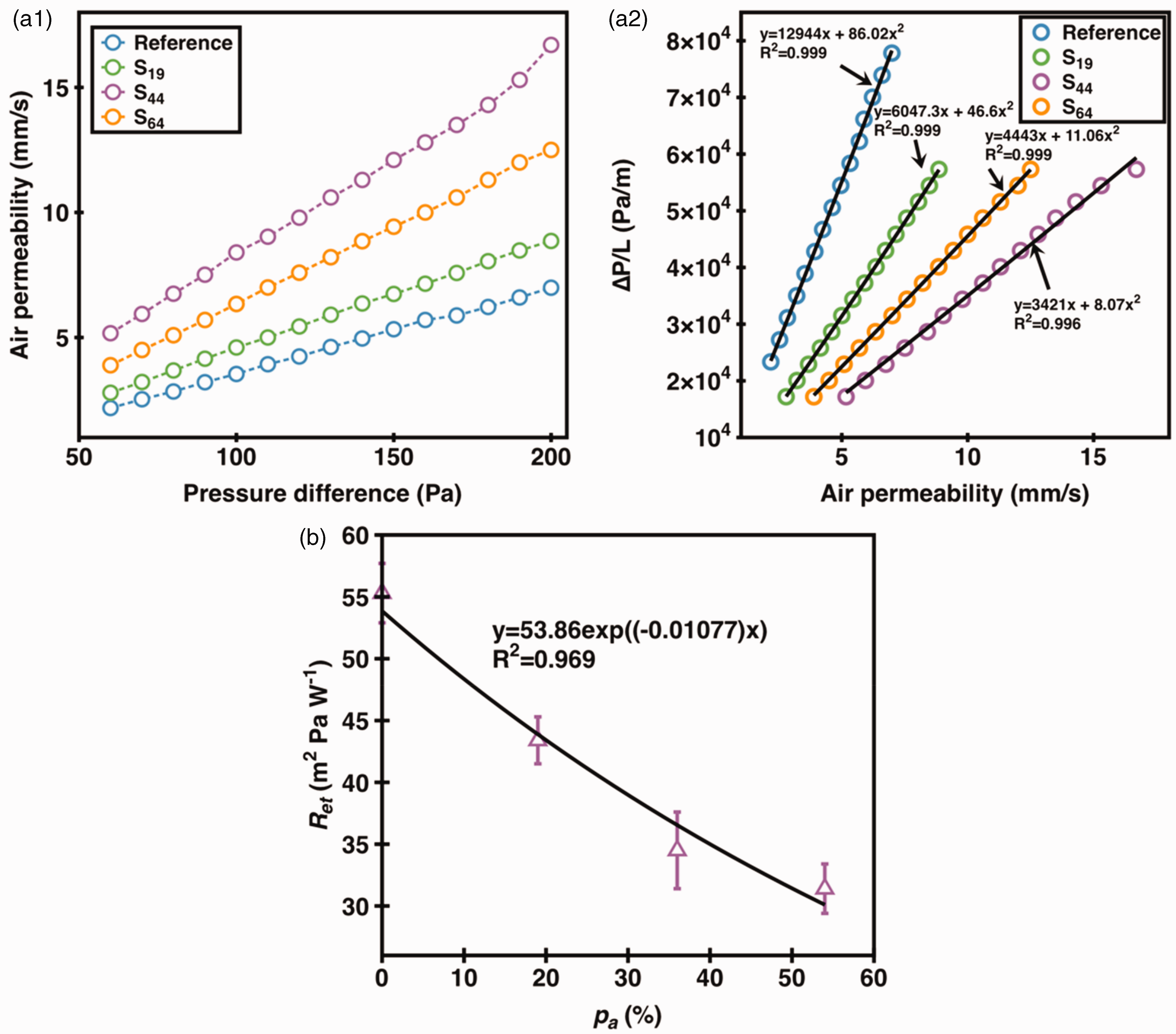
Air permeability with various pressure differences (a1), plots of
The measuring apparatus used for the air pocket-incorporated SFPE entails the uniform distribution of PCM pockets in a square, whereas the FT3300 device possesses a circular measuring area. 44 This dissimilarity leads to disparate airflows and drag forces. Consequently, S44 exhibits a greater air permeability value than S64.
The inclusion of an air gap within the samples is also noted. Air pocket-incorporated SFPE exhibits greater air permeability when compared with S0, which possessed a similar multi-layer fabric structure without PEG loading. The addition of PEG in SFPE results in the increased thickness of SFPE, creating a larger air gap along the cross-section. This facilitates the passage of air through the entire SFPE structure.
Figure 4(a2) presents plots of
Figure 4(b) presents the Ret values of air pocket-incorporated SFPE. The samples S0, S19, S44 and S64 have Ret values of 55.3, 43.4, 34.5 and 31.4 m2 Pa W−1. It is found that the Ret value is decreased with increased pa values. It is caused by more paths for water vapor to transfer through the whole SFPE. To predict the relationship between Ret value and pa value, the exponential function was used and R2 reached 0.969.
Phase transition and thermal energy storage of the breathable SFPE
According to previous work,37,38 only viscose fabric and PU nanofibrous membranes affect the phase transition behavior of PEG in SFPE. Thus, three samples are the objectives to reveal phase transition and thermal energy storage, including pure PEG, PEGV5-1 and UPEGV5-1. Figure 5(a) presents DSC curves of pure PEG, PEGV5-1 and UPEGV5-1, and DSC results are given by Table 4.
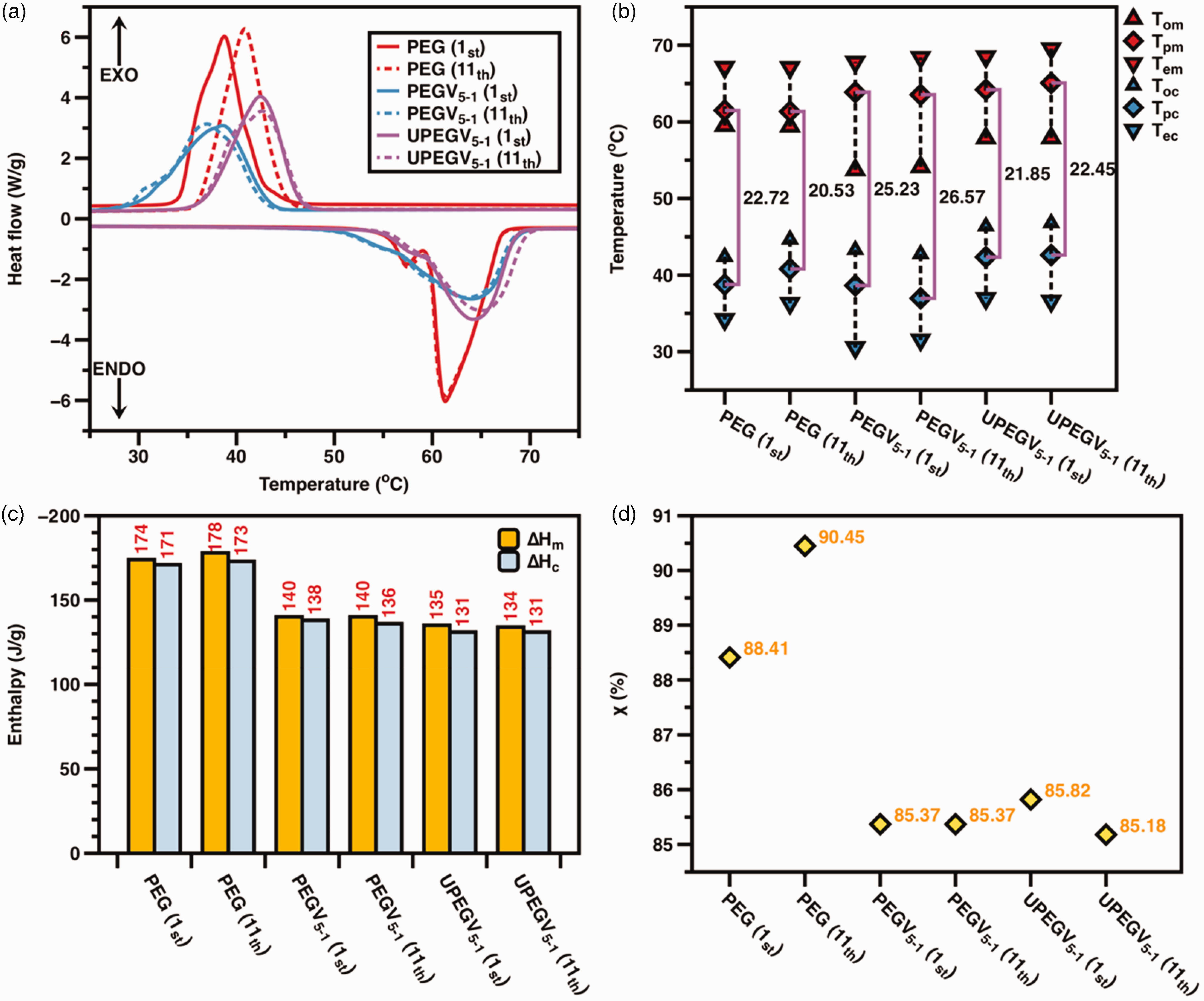
Differential scanning calorimetry (DSC) curves (a); phase transition (b); thermal energy storage (c); and relative crystalline degree (d).
DSC results of PEG, PEG-coated viscose fabric and PU nanofibrous membrane-covering PEG-coated viscose fabric
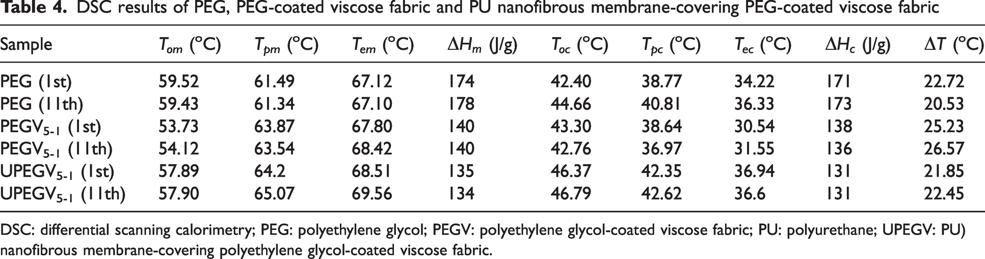
DSC: differential scanning calorimetry; PEG: polyethylene glycol; PEGV: polyethylene glycol-coated viscose fabric; PU: polyurethane; UPEGV: PU) nanofibrous membrane-covering polyethylene glycol-coated viscose fabric.
Analysis of phase transition
The phase transition range of pure PEG, PEGV5-1 and UPEGV5-1 is shown in Figure 5(b). Obviously, both the first and 11th DSC curves of PEGV5-1 and UPEGV5-1 are almost overlapped, while there is a significant right shift of melting points for PEG after 10 heating/cooling cycles. The SFPE has a stable phase transition behavior after heating/cooling cycles. Furthermore, both the melting range and solidifying range of PEGV5-1 and UPEGV5-1 are higher than PEG, which is caused by the effect of the viscose fabric and PU nanofibrous membrane on the self-crystalline behavior of PEG. In addition, the supercooling degree (
Analysis of enthalpy value and relative crystalline degree
The enthalpy values of pure PEG, PEGV5-1 and UPEGV5-1 are shown in Figure 5(c) and (d). The UPEGV5-1 has
By considering the mass of two protection layers, the overall enthalpy value of the PCM pocket is 55 J/g, and the overall enthalpy values of breathable SFPE range from 27 J/g to 48 J/g, which was calculated according to equations (7) and (8). In addition, the order of enthalpy values is PEG > PEGV5-1 >UPEGV5-1. Apart from a relatively smaller amount of PEG in PEGV and UPEGV, the crystallinity of PEG accounts for the reduced enthalpy values. According to equations (5) and (6), the relative crystalline degree (
Comparison of our work with other published work related to breathable PCM-containing textiles
To reveal both advantages and disadvantages of the breathable SFPE, a comprehensive comparison with other published work related to breathable PCM containing textiles is investigated. The breathable SFPE contains both PCM and air pockets, with the PCM pocket similar to the PCM-coated area in MPCM fabrics incorporating air pockets. Thus, two comparisons are considered to facilitate comprehension of the prospective utility of the breathable SFPE, including the enthalpy value of the PCM pocket and the overall enthalpy value.
Obviously, the enthalpy of the PCM pocket at about 135 J/g is significantly higher than the MPCM coating layer in the air pocket-incorporated MPCM-coated fabrics, as presented in Table 5. It is caused by a high loading amount of PEG in the PCM-loaded layer. In addition, the overall enthalpy value of SFPE ranges from 27 J/g to 48 J/g according to equation (8), which is higher than the overall enthalpy value of reported PCM containing fabrics (including PCM-coated fabric and MPCM-coated fabric) (presented in Table 6). A higher overall enthalpy value supports a better thermal buffering effect and temperature regulation. Furthermore, the overall enthalpy value is notably impacted by the areal density of the protective layer. The use of a protection layer with lower areal density resulted in a higher overall enthalpy value.
Comparison in enthalpy of PCM pocket and overall air permeability of breathable SFPEs with air pocket-incorporated MPCM-coated knitted fabric 53
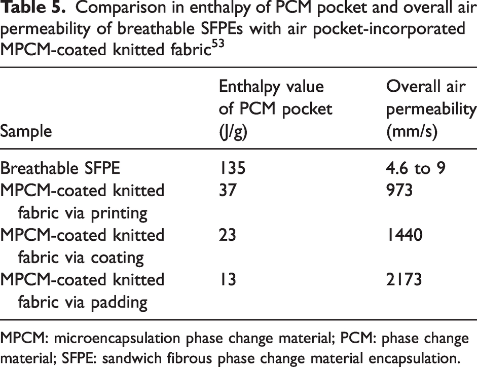
MPCM: microencapsulation phase change material; PCM: phase change material; SFPE: sandwich fibrous phase change material encapsulation.
Comparison in overall enthalpy values, PCM loading amount and air permeability of breathable SFPE with reported PCM textiles
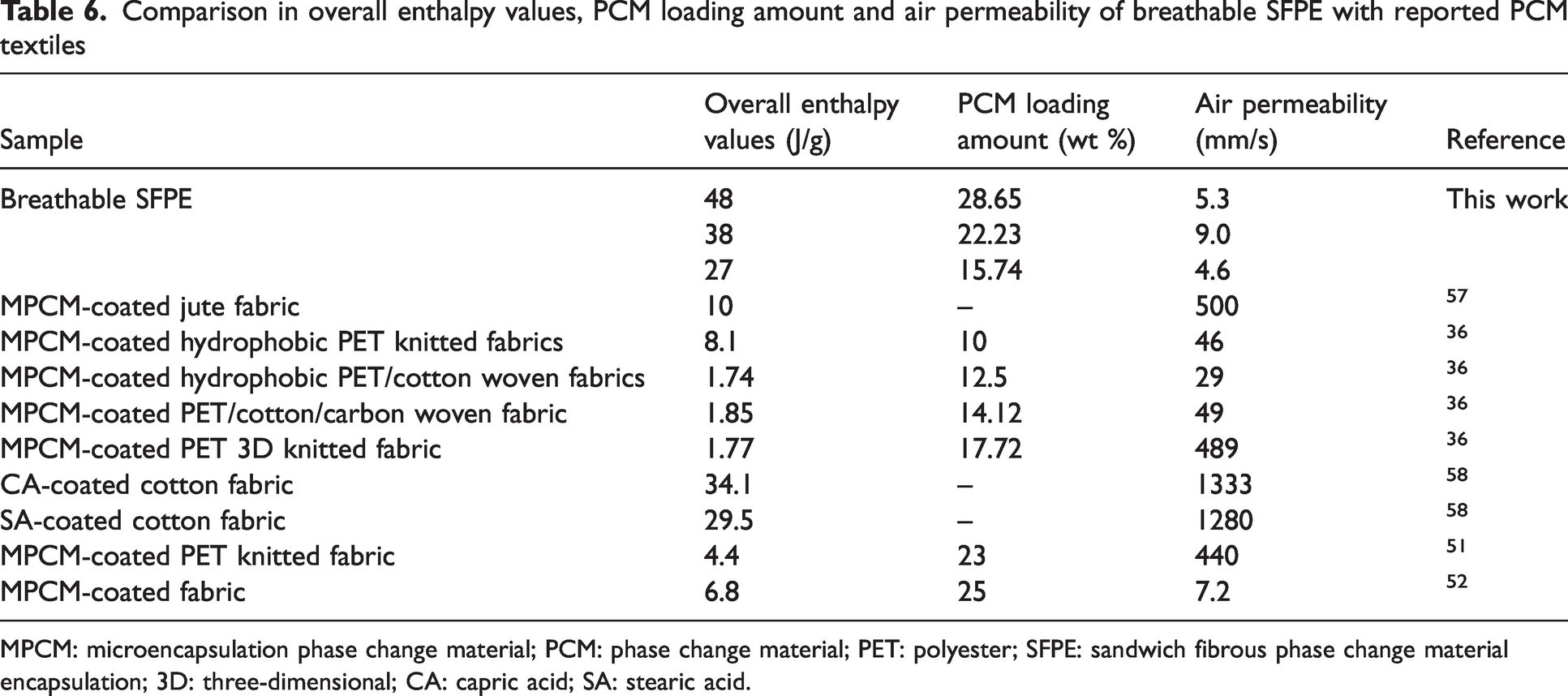
MPCM: microencapsulation phase change material; PCM: phase change material; PET: polyester; SFPE: sandwich fibrous phase change material encapsulation; 3D: three-dimensional; CA: capric acid; SA: stearic acid.
Although there is a high PCM loading amount and high overall enthalpy value of the breathable SFPE, the air permeability of the breathable SFPE ranging from 4.6 mm/s to 9 mm/s is much lower than reported PCM-containing textiles. Two layers of PU nanofibrous membranes are used as a barrier layer inside SFPE, and results in low air permeability.
Thermal buffering effect of breathable SFPE
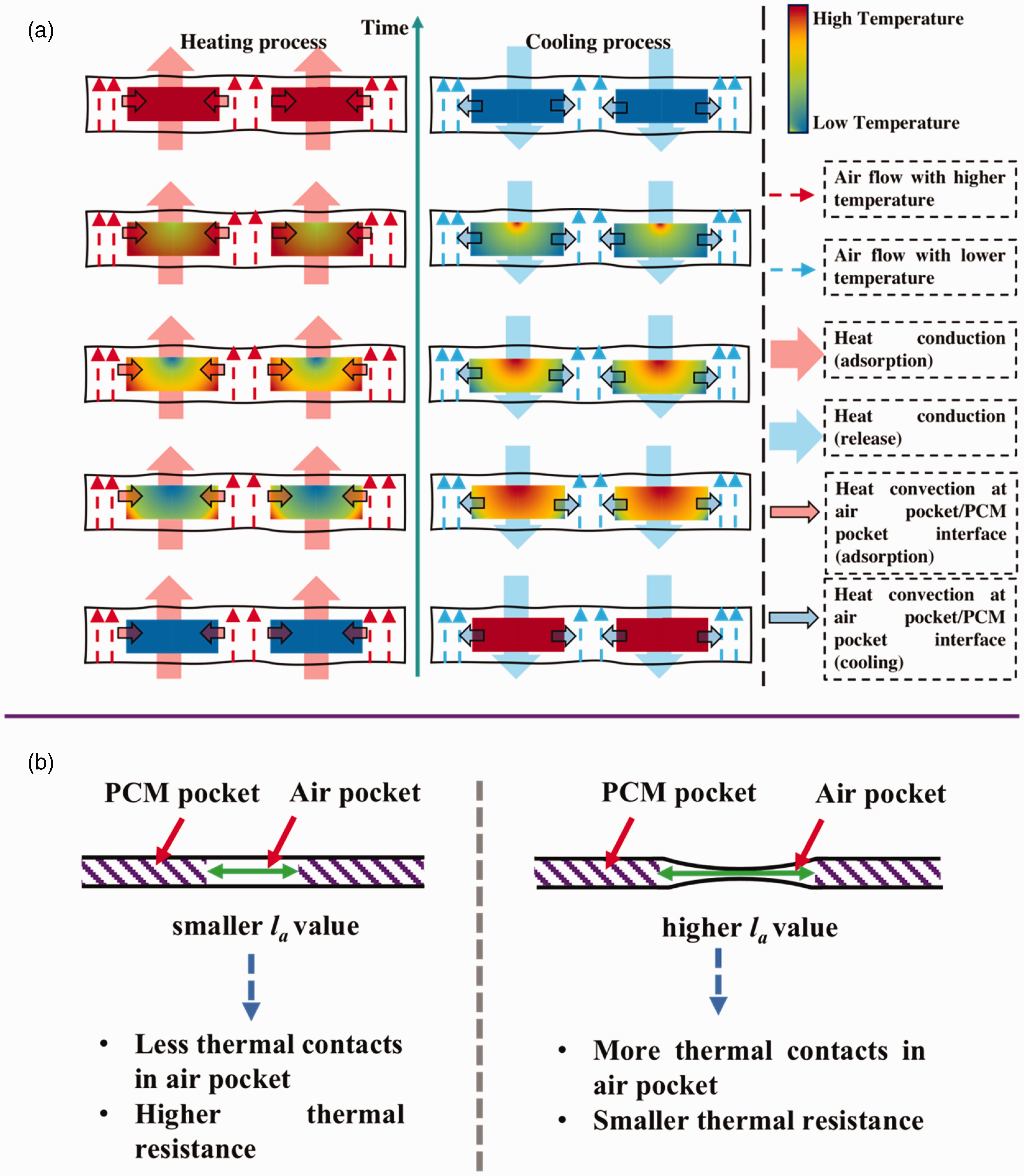
As there is a heterogenous structure of the PCM-loaded layer in the breathable SFPE, the air pocket and PCM pocket has a different T-history. For instance, Figure 6(a) displays the FLIR images of sample S44 undergoing the heating/cooling process, illustrating the varying temperature values of the air pocket and PCM pocket. Furthermore, the temperature change recorded in the PCM pocket indicates that the process of phase transition initiated at the pocket's border and extends toward its center. This variation is attributable to the disparities in the heat transfer mechanism, as shown in Figure 8(a). The phase transition of PEG at the perimeter of the PCM pocket commences earlier and exhibits a quicker rate of change due to the coupling of thermal conduction and thermal convection. In contrast, the phase transition of PEG at the center of the PCM pocket is solely impacted by thermal conduction.
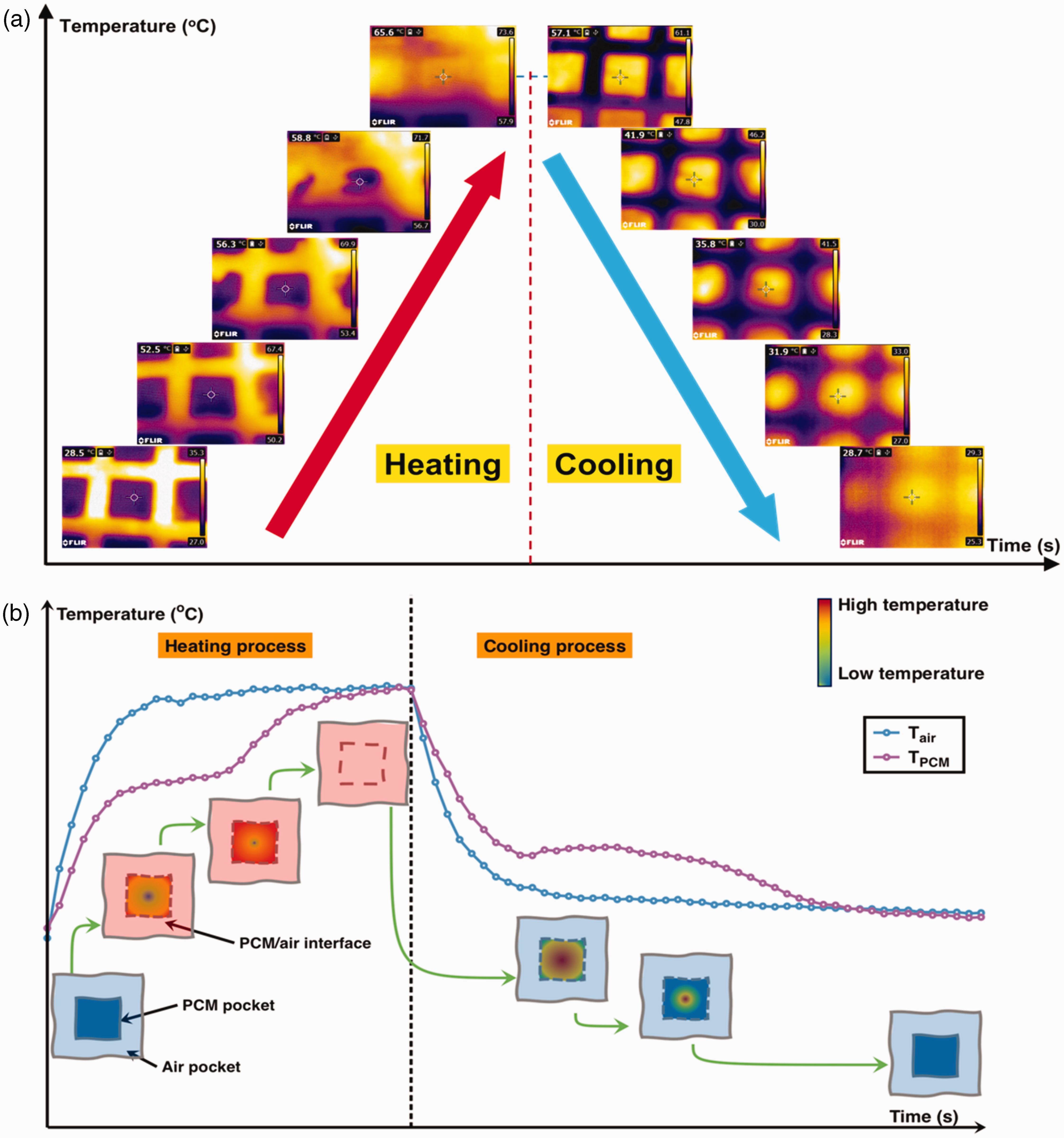
FLIR images of the phase change material (PCM) pocket of S44 during the heating and cooling process (a); and the scheme for the surface temperature change of the PCM pocket and air pocket of breathable sandwich fibrous phase change material encapsulations (b).
Thus, the T-history of the breathable SFPE could be shown as in Figure 6(b). Then, it is necessary to specify the T-history of the PCM pocket and air pocket of the breathable SFPE, which is shown in Figure 7(a) and (b), respectively. It is evident that the PCM pocket takes a longer time than the air pocket to reach the final stable temperature during the heating/cooling process. This provides evidence in support of the thermal buffering effect by the PCM pocket.
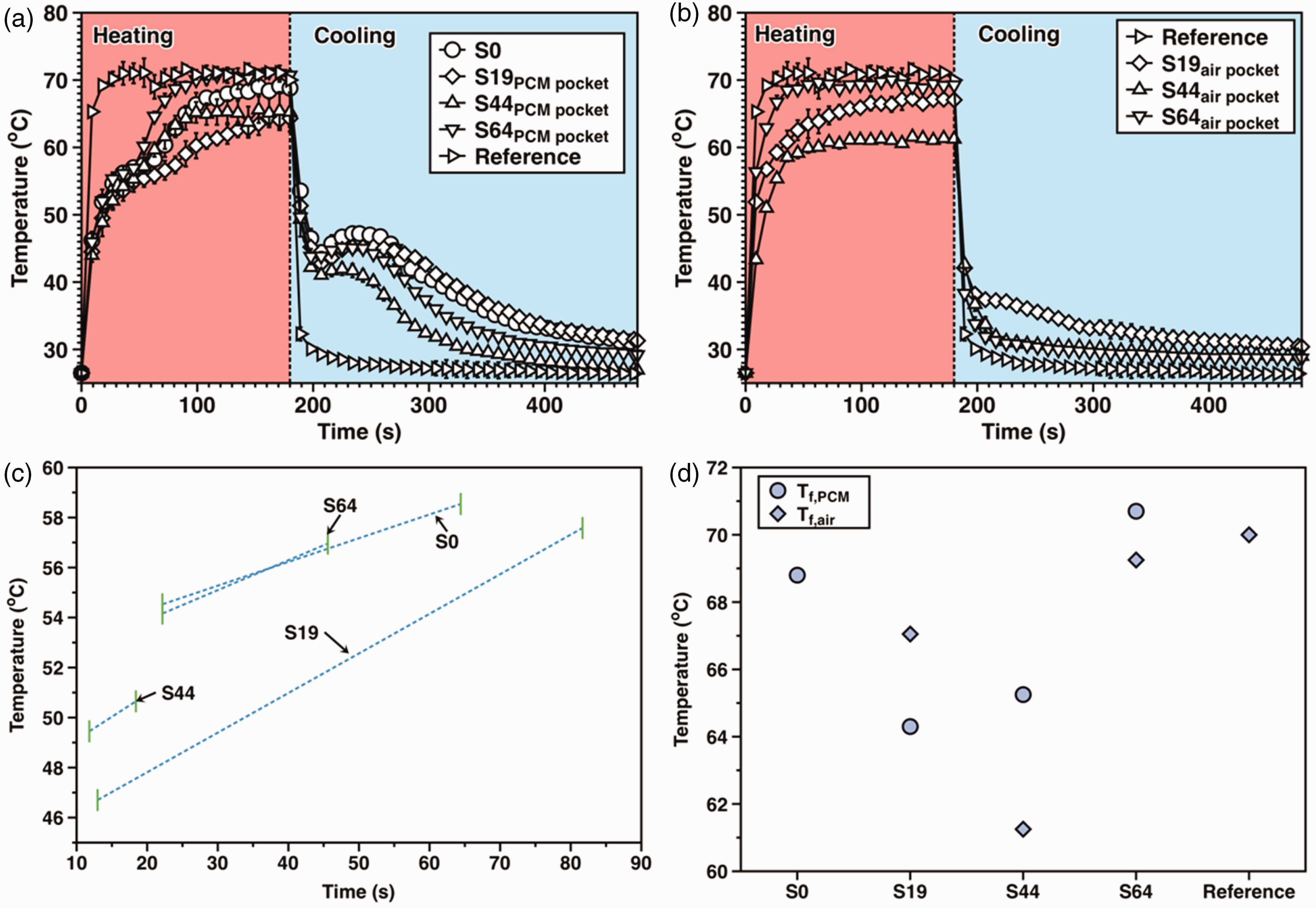
T-history of the phase change material (PCM) pocket (a) and air pocket (b); estimated thermal buffering effect range according to the tangent method (c) and the final temperature of the PCM pocket and air pocket (d).
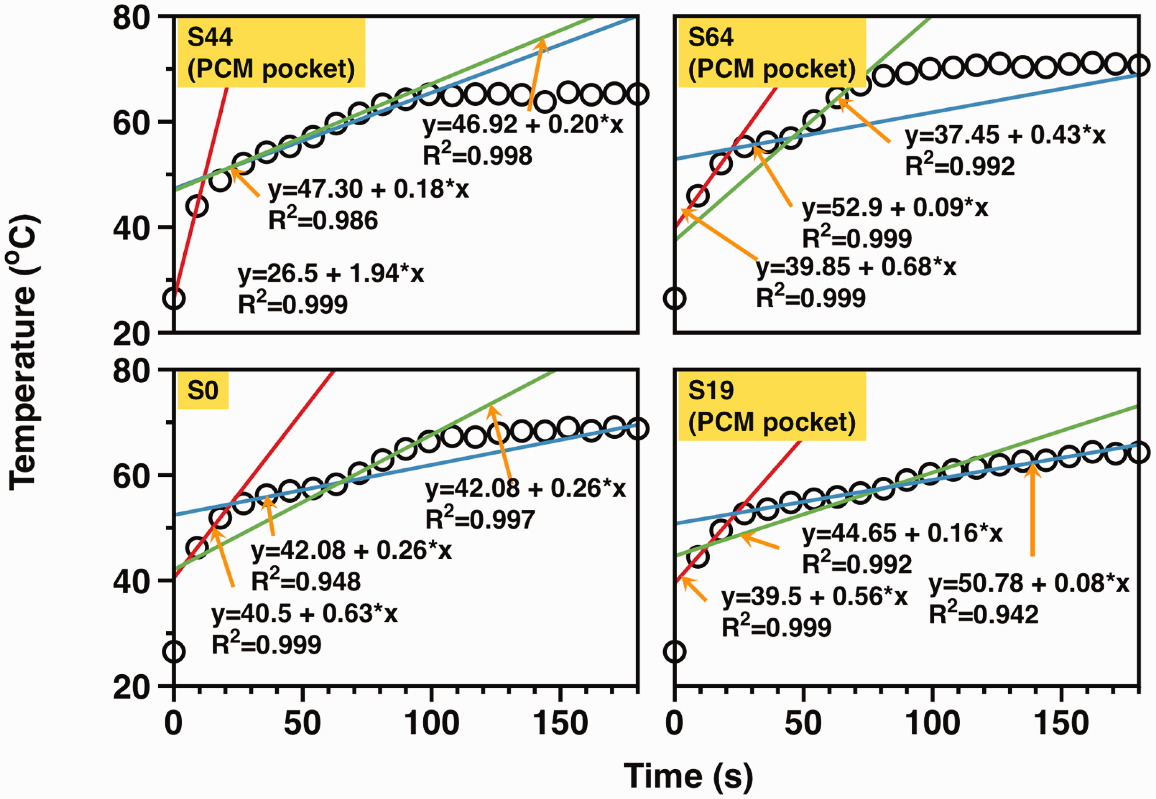
Analysis of heating T-history
To characterize the heating T-history of the PCM pockets in all samples, we applied tangent lines based on observations from three platforms, which were mathematically used to determine turning points. By identifying points of intersection between adjacent tangent lines, we obtained two turning points. Figure 9 displays the application of tangent lines on the heating temperature history of the PCM pocket, while Figure 7(c) presents the results. The longest thermal buffering effect range during the heating process is observed in sample S19, whereas sample S44 has the shortest thermal buffering effect range. In addition, Figure 7(d) displays the final temperature (Tf,PCM) of the PCM pocket with no apparent trends. Regarding the order of Tf,PCM, it is found to be S64 > S0 > S44 > S19.
Furthermore, it takes a longer time for the air pocket of the breathable SFPE to reach a final stable temperature when compared with the reference sample. Thus, there must be a mutual influence of heat transfer between the PCM pocket and air pocket. In addition, Figure 7(d) presents the final temperature (Tf,air) of the air pocket, and there are no obvious trends. The order of Tf,air is: reference > S64 > S19 > S44.
Thus, the influence of the la value on the heat transfer through the whole SFPE is complicated. The reason could be as follows:
As illustrated in Figure 8(a), the combination of heat conduction and heat convection generates the T-history, which is significantly affected by the la value. When the la value is lower, a significant contribution of heat conduction is observed, resulting in a more apparent thermal buffering effect. Conversely, when the la value increases, the air pocket size increases, and the influence of heat transfer through the air pocket becomes less significant, leading to a reduced effect of heat storage within the PCM pocket. Consequently, the thermal buffering effect range can be directly proportional to the la value or the air pocket size.
Diagram for heat transfer through breathable SFPE (a) and effect of la on the heat transfer through the air pocket (b). Tangent lines for heating T-history of all the samples (red line, blue line and green line: sample with solid phase change material (PCM), sample with PCM in phase transition state, and sample with PCM in molten state). For the final temperatures of the air pocket and PCM pocket, they result from the overall thermal balance between the PCM pocket and air pocket during the heating process. Changing the la value alters the overall dynamic thermal resistance of the SFPE. Figure 8(b) shows that the air pocket size is different when the la value is large enough due to the inherent bending property of the barrier layers (PU nanofibrous membrane). In this instance, more thermal contacts are found and result in lower thermal resistance. The larger air pocket should have resulted in a higher value for Tf,air. In addition, due to the larger la value, the mutual influence between the PCM pocket and air pocket is reduced. This allows for heat transfer through the PCM pocket and air pocket to be roughly considered as a single direction. As a result, the Tf,PCM value is smaller than Tf,air, as the thermal resistance of the melting PCM is lower than that of air. For heat transfer through sample S44, there is a variance compared with S19 and S64. It is possible for sample S44 to belong to the situation depicted in Figure 8(b). During the heating process, the overall thermal resistance is optimally maximized. The air pocket exhibits the highest thermal resistance due to the well-preserved shape and the significant amount of air enclosed. Due to the larger la value, the mutual influence between the PCM pocket and air pocket is minimized resulting in S44 having the lowest value of Tf,air. So, the value of Tf,PCM exceeds that of Tf,air.
Analysis of cooling T-history
For all the cooling T-history curves of PCM pockets, the classic shape with a peak was found, which was caused by self-heating of PCM during the cooling process. As shown in Figure 7(a) and (b), the order of maximum peak was: S0 > S19 > S64 > S44. Generally, a bigger peak supported higher thermal energy storage and better temperature regulation. Furthermore, the shape of the peak (e.g. peak position, peak value, and peak area) is the appearance of the thermal energy release degree when self-heating of PCM occurs. The higher the temperature difference between the PCM pocket or air pocket and the environment, the peak should be sharper. For all the cooling T-history curves of air pockets, only sample S19 had a peak while the other three samples had a simple cooling T-history. Furthermore, the order of final stable temperature was: S19 > S44 >S64 > Reference sample. So, the self-heating behavior of the PCM pocket affected the cooling of the air pocket.
As described in the Section ‘Analysis of heating T-history’, the specific cooling T-history of the SFPE was caused by the combination of heat conduction and heat convection:
When the la value is small (e.g. sample S19), the higher thermal energy of PCM pocket is found. During the cooling process, the high thermal resistance is found when the self-heating of PCM occurs. Then, the temperature difference between the air pocket and PCM pocket tends to be higher, and heat transfer from the PCM pocket to air pocket occurs. Correspondingly, it takes a longer time for the air pocket to cool down. When the la value is increased, the effect of the PCM pocket on the T-history of the air pocket is reduced. However, the smaller PCM amount is found, which results in the reduced overall thermal energy storage. So, for sample S44, the peak of the PCM pocket is smaller than sample S19 and the cooling T-history of the air pocket becomes a simple shape. When the la value keeps increasing, the effect of the PCM pocket on the T-history of the air pocket is further weakened, and the heat loss of the PCM pocket becomes more significant. Then, the shape of the cooling T-history of sample S64 is sharp, even higher than S44. In addition, the final stable temperature of the cooling T-history of the air pocket of S64 becomes smaller than S44. By referring to Figure 8, it is caused by a smaller air amount in the air pocket when the la value is too large.
Practicability of breathable SFPE
According to the aforementioned results, sample S64 has an optimized thermal energy storage and breathability. Therefore, sample S64 is used to reveal the practicability. As shown in Figure 10 (a1), (a2), and (a3), the flexibility of the breathable SFPE is highlighted. On one hand, the flexibility is contributed by the air pocket inside SFPE as a flexible part to allow SFPE to be folded. On the other hand, the recovery is caused by the usage of commercial binders and protection layer (PET fabric with hydrophobic coating).
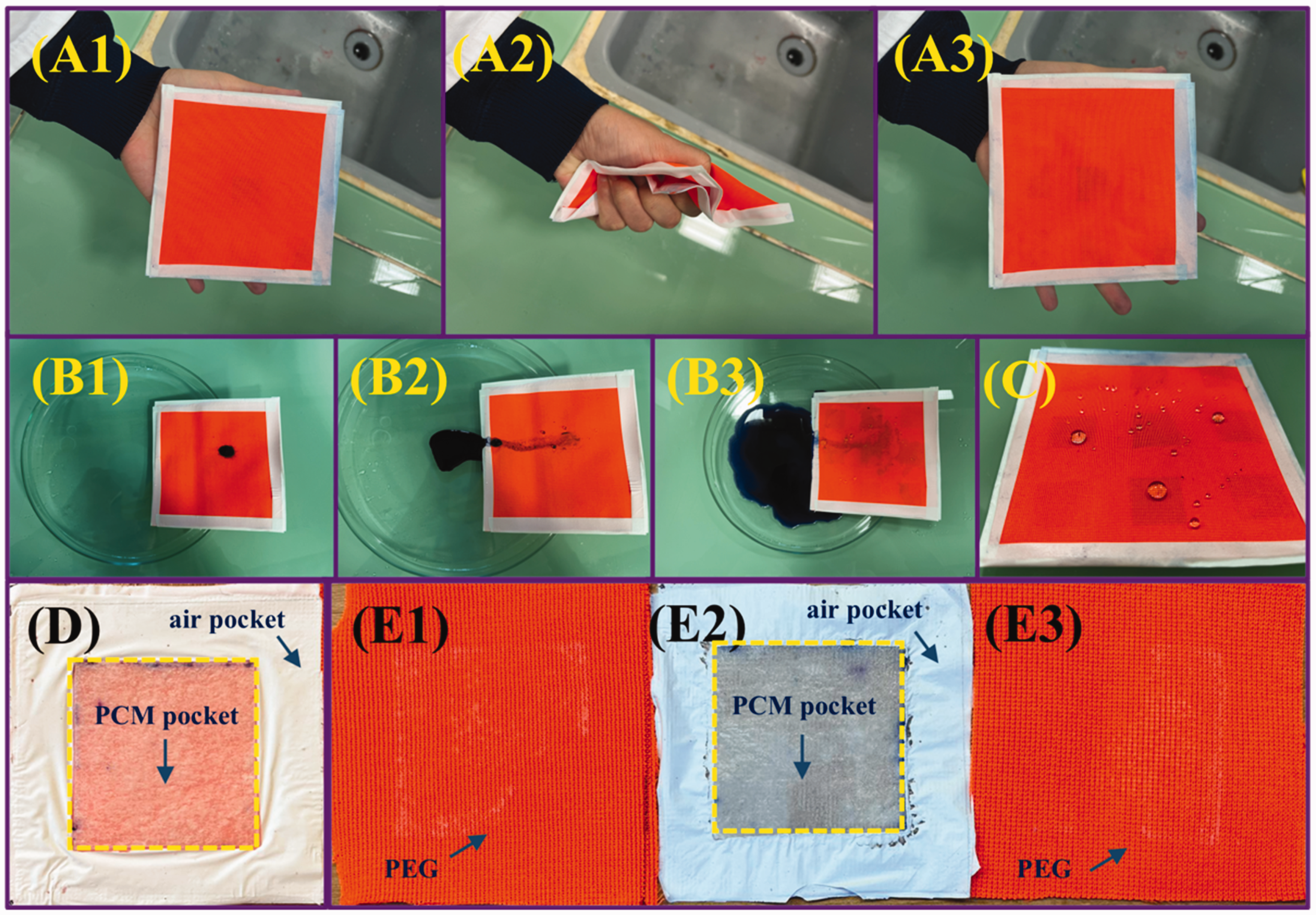
Practicability of sandwich fibrous phase change material encapsulation (SFPE). (a1), (a2), and (a3) SFPE in the hand, knead SFPE with the hand, and SFPE after kneading; (b1), (b2), and (b3) dyes on the SFPE, washing of dyes on the SFPE with a small amount of water, and washing of dyes on the SFPE with a large amount of water; (c) distribution of various water droplets on the SFEP; (d) interface between the phase change material (PCM) pocket and air pocket of the mini sample before immersion in water; (e1) polyethylene glycol (PEG) on the first protection layer of the mini sample after immersion in water; (e2) interface between the PCM pocket and air pocket of the mini sample after immersion in water; and (e3) PEG on the second protection layer of the mini sample after immersion in water.
Therefore, it is recommended that breathable SFPE is suitable for various human body parts (e.g. safeguarding the chest, arms, and legs) with optimal compatibility with textiles.
As a PET fabric with hydrophobic coating is utilized as a protective layer, the waterproof and self-cleaning capabilities for the breathable SFPEs are obtained. For example, the self-cleaning of the S64 sample is shown in Figure 10(b1), (b2), and (b3), and the majority of dyes were simply dropped out. In addition, 1 mL water droplets were efficiently deposited on the SFPE surface as presented in Figure 10(c), and the waterproof property of the breathable SFPE is found.
To reveal the protection of the breathable SFPE for encapsulated PEG from water, the mass and diffusion of PEG inside the mini sample with the same structure as SFPE were evaluated. The mass of the mini sample after immersion in water is 1.33 g, and is close to the mini sample with mass of 1.34 g before immersion in the water. In addition, the interface between the PCM pocket and air pocket of the mini sample after immersion in water is kept almost the same as the one before immersion in water, which is shown in Figure 10(d) and (e2). The PEG is well kept inside the multi-layer fabric structure even after immersion in water. However, partial PEG is attached on the inner sides of the protection layer after immersion in water, which is shown in Figure 10(e1) and (e3). Therefore, the immersion of the sample in the water does not significantly result in the leakage of PEG.
Furthermore, the abrasion of the breathable SFPE was evaluated, and the failure of the abrasive protection layer to be hydrophobic is considered to result in leakage of PEG because of the multi-layer fabric structure. The abrasion results and the hydrophobicity of the abrasive protection layer are shown in Figure 11. Until 7000 abrasion times, the perfection layer still has a stable structure because there is no damage to the abrased surface. With increased abrasion times from 500 to 7000, the water contact angle tended to decrease from 129° to 123°. This means that the hydrophobic coating layer is well deposited on the PET fabric even after abrasion. Due to the excellent abrasion resistance of the protection layer, the sample SFPE has a highly stable structure in which the PCM loaded layer and barrier layer are well safeguarded. Therefore, the sample SFPE has a great potential in application.
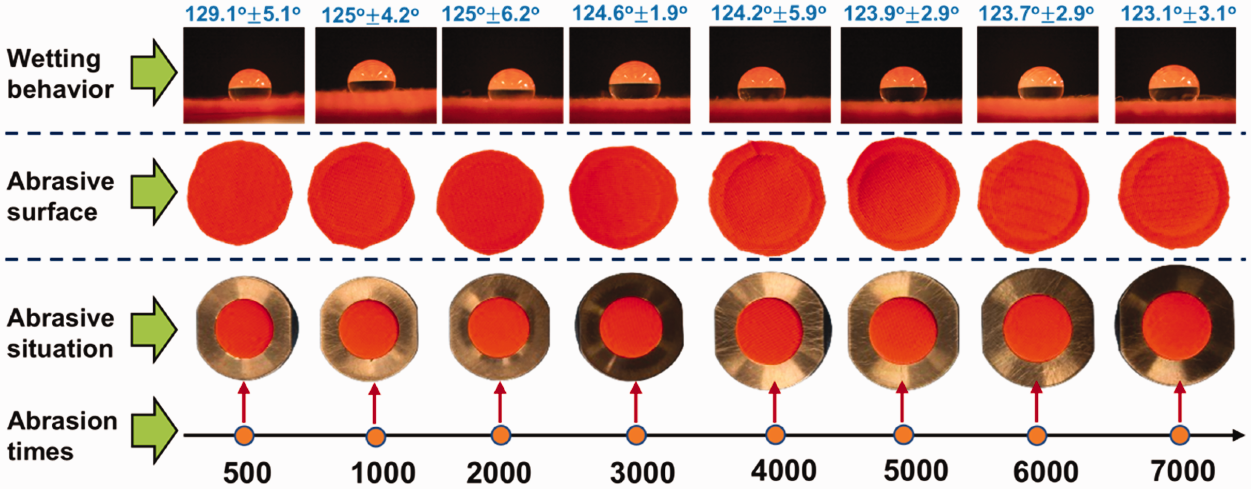
Abrasion behavior of the protection layer and hydrophobicity of the abrased protection layer.
Basic structure of sandwich fibrous phase change material (PCM) encapsulations.
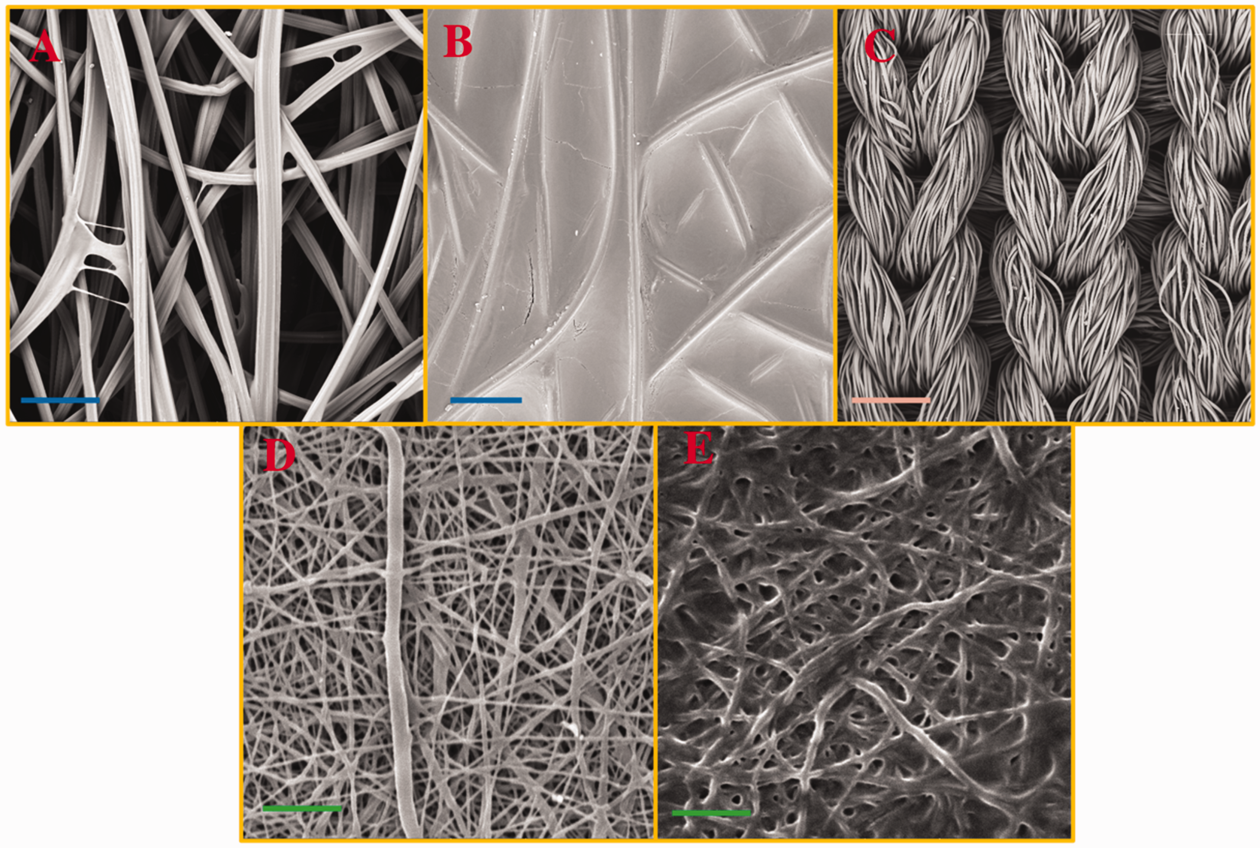
Morphology of viscose fabric (a); polyethylene glycol-coated viscose fabric (PEGV) (b); hydrophobic polyester (PET) fabric (c); polyurethane (PU) nanofibrous membrane (d); and PU nanofibrous membrane-covering polyethylene glycol-coated viscose fabric (UPEGV) (e). Blue, yellow and green scale: 100 µm, 500 µm, and 5 µm.
Conclusions
In this study, we have successfully fabricated a breathable sandwich fibrous phase change material (PCM) encapsulation (SFPE) with PEG as PCM, which consists of a PCM-loaded layer, barrier layer and protection layer. The PCM-loaded layer is uniformly split into the PCM pocket and air pocket to allow water vapor and air to penetrate through. Although there is 64% of air pocket inside the PCM-loaded layer, the breathability is low, and it is attributed to the presence of two layers of PU nanofibrous membranes. In addition, it is possible to construct a nonuniform displacement of the PCM pocket and air pocket to enhance the breathability. As there is a high PCM loading amount, the overall enthalpy value of SFPE ranges from 27 J/g to 48 J/g, which is higher than the current PCM-containing fabrics. Furthermore, the thermal buffering effect is a combination of the PCM pocket and air pocket. Different from the simple SFPE without an air pocket, the mutual heat transfer between the PCM pocket and air pocket results in a complicated thermal buffering effect. In addition, the breathable SFPE has a good practicability, including wearability, hydrophobicity, self-cleaning behavior, and flexibility. The PEG can be kept well in the breathable SFPE even after immersion in the water for 2 h.
Overall, we assert that the breathable SFPE with PCM possesses significant potential for diverse applications. In addition, the study offers insights into the potential use of nanofibrous membranes in the multi-layer fabric system.
Footnotes
Acknowledgements
Kai Yang would like to thank Dr. Tao Yang for his valuable advice and feedback regarding this work.
Declaration of conflicting interests
The author(s) declare that they do not have any commercial or associative interest that represents a conflict of interest in connection with the work submitted.
Funding
The author(s) disclosed receipt of the following financial support for the research, authorship, and/or publication of this article: This work was supported by the project ‘Advanced structures for thermal insulation in extreme conditions’ (reg. no. 21-32510M) granted by the Czech Science Foundation (GACR).