
Abstract
Ultraviolet (UV) bonding technology is widely used across industries. As the curing reaction is initiated via an external light source, the use of fast-curing structural UV acrylates has so far been limited to joint designs with at least one transparent joining part. By introducing a side-emitting polymer optical fiber textile into the adhesive layer, which acts as an embedded light source, the technology can be made accessible for applications with nontransparent substrates such as metals. This paper describes the development of extra thin polymer optical fiber narrow fabrics designed to enable curing of structural adhesive joints. Polymer optical fibers (warp) were combined with different low-titer polyester weft yarns in two fabric design types with different primary out-coupling mechanisms: undulation and surface modification of the polymer optical fibers. The effect of yarn properties, thread densities and weave on fabric quality, geometry and lateral light intensity of each type were investigated. Results showed that narrow fabric production within the tight geometric limits required is feasible. Fabrics manufactured with nontextured yarns at low titers and low weft densities exhibited the highest lateral light intensities for the surface modification type fabric. To compensate for intensity loss over fabric length, investigating light coupling from both sides is recommended for this fabric type. For the undulation type fabric, the lateral light intensity characteristics indicated that the high tenacity yarns are promising candidates for the fabrication of low sidelight attenuation fabrics through modulation of the weft density.
Polymer optical fibers (POFs) are used as versatile light guides in a wide range of applications such as data transmission, fiberoptic sensors as well as illumination.1,2 Light propagation in POFs is based on the principle of total internal reflection. 2 A simple way to obtain planar illumination in textiles involves using side-emitting polymer optical fibers (SE-POFs). In these, lateral light emission is achieved through a range of scattering mechanisms which partially inhibit total internal reflection. Modification methods include doping as well as surface alteration by thermal, mechanical or chemical treatment of the POF. Most of these methods can also be used alternatively as a post-processing step on textiles incorporating untreated POFs to create lateral light emission. A more complex approach to induce side emission is by introducing bends along the POF. This effect allows for manufacturing of luminous POF textiles without pre-processing of the POF or post-processing of the textile, for example, by exploiting the undulation of the POF when used as warp or weft thread in a woven fabric.3–5
Lateral light emission of SE-POFs, or respectively side-emitting POF textiles decreases with increasing distance from the light source. 6 Strategies to counteract this effect include a gradually increasing surface modification density, 4 simultaneous light in-coupling from both fiber ends7,8 or variation in weft density, if the POFs are used as warp in a woven fabric.9,10
As described by Seewald et al., 11 SE-POFs can be used to cure ultraviolet-curable adhesives (UV adhesives) by transmitting the UV light of an external light source into an adhesive joint which enables bonding of nontransparent parts with UV adhesives. UV adhesives are radiation-curing adhesives which, in case of widely used acrylate-based radical curing systems, contain photoinitiators. On light excitation within a formulation-dependent wavelength range, these set off a rapid chain-growth polymerization. 12 Among the main advantages of these UV acrylates are short curing times and no restrictions from pot life – which allows for controlled curing-on-demand. The curing process is not reliant on the presence of humidity or metal catalysts and does not require energy-intensive heat application. Consequently, these UV adhesive systems are popular across different industry sectors, including automotive 13 and medical. 14 Applications also cover consumer and industrial electronics 13 (e.g. touch screen 15 or solar panel 16 assembly) as well as glass bonding (from optical components 17 to glass facades). 18 However, their biggest drawback is the limitation to joints with at least one transparent adherend to allow for uniform exposition of the adhesive by the external light source. 19
In the study 11 exploring the feasibility of substrate-independent UV curing, the usage of single POFs for curing was found to be unsuitable for most industrial applications, as the UV absorption within the adhesive only allowed for a range of about 2.5 mm around the POF to be cured when using POFs with a diameter of 1.0 mm. Moreover, introducing POFs with such a high diameter into the adhesive joint increases the thickness of the adhesive layer above established industry standards and comes at the cost of reduced mechanical properties. 12 Based on feedback from manufacturers, typical layer thicknesses for these adhesive systems range around 0.20 mm and below with a technical feasibility limit at around 0.05 mm. 12
As shown in a consecutive study by Kallweit et al., 20 the decrease in transmittable optical power connected to a reduction of the POF diameter can be overcome by adjusting the number of POFs in the adhesive joint accordingly. The authors explored this concept by weaving POFs into fabrics. When used in a textile, POFs are usually processed into woven fabrics resulting in lower bending-induced light losses and thus more homogeneous illumination compared with other textile structures.5,21,22 The light loss is dependent on the chosen weave.23,24
The motivation behind this study is to advance the concept proposed by Kallweit et al. 20 significantly by developing a fabric design optimized for integration into structural adhesive joints. In this context, an important design goal is to enable uniform curing of the UV adhesive. This requires symmetrical illumination for the two fabric sides and thus an even-sided fabric design. To optimize the curing efficiency, homogeneity of the emission profile is desirable.
POF fabrics have first been conceptualized in a patent from 1967, shortly after the invention of POFs themselves.21,25 POF fabrics have been examined in numerous studies.22,26–31 However, most of them were aimed at maximizing the emission on one side of the fabric (e.g. via weave pattern or fabric post-processing), as for most illumination applications only one side of the fabric is visible. Quandt et al. 8 examined different even-sided weave patterns and weft density adjustments for POF fabrics to maximize and homogenize the lateral intensity for the treatment of neonatal jaundice with a textile phototherapy approach using a peak wavelength of 470 nm. The parameter study concentrated on fabrics made from in-house produced cycloolefin polymer based POFs8,32 as weft and commercial modified polyester yarns as warp with POF undulation as the sole out-coupling mechanism. For this, the authors put an emphasis on the optimization of the POF density of their fabric. For the same application Cochrane et al. 33 integrated multiple satin weaves in a single uneven-sided POF fabric combining poly(methyl methacrylate) (PMMA)-POFs as weft with polyester warp yarn. They achieved homogeneous planar illumination for the measured fabric side at 635 nm wavelength. Employing a plain weave, a symmetrical luminous pattern was achieved by Shen et al. 34 However, the authors treated their POF fabric with a carbon dioxide (CO2) laser to create the textile display, thereby also causing predominant light emission to one side of the fabric.
Companies like MUNDA Textile Lichtsysteme GmbH (Erkrath, Germany), Brochier Technologies (Villeurbanne, France) and DreamLux Samsara S.R.L. (Milan, Italy) produce POF fabrics for wearables, home textiles and car interior lighting.35–37 However, all commercial POF fabrics are either optimized for light emission on one side of the fabric or the fabric thickness is too high for integration into adhesive joints.
There is a wide set of parameters determining the illumination properties of a POF fabric. Wang et al. 38 evaluated bending-induced lateral emission for POF fabrics of 13 different sateen-derived weaves and concluded that the lateral intensity is mainly related to the POF bending radius and its float in the weave pattern. In a manufacturing context, this translates to a dependency on the undulation characteristics of the POFs within the fabric. These are not only governed by weave, properties of the weaving materials (mechanical and physical) as well as thread densities but also by weaving parameters such as warp and weft tension. For instance, building on their original fabric design, 33 in their more recent work, Cochrane and Koncar 24 demonstrated the potential for further improvement of illumination homogeneity by optimization of the warp tensions. Masuda et al. 39 additionally mention POF diameter and light source characteristics as factors for the luminosity of a POF fabric. With regard to the emission profile over the fabric length, attenuation losses within the POF also need to be taken into account. These generally depend on the optical properties of the POF and the wavelength spectrum of the light source. 1 Seewald et al. 11 identified a peak wavelength of 400 nm as most effective for curing of typical structural UV acrylates by means of PMMA-POFs. Furthermore, the type and amount of photoinitiators in the adhesive as well as the radiation intensity are the main factors affecting the curing process. 40 When investigating the suitability of a POF fabric design for a structural application, weave and weft density are also of interest with respect to the mechanical load-bearing capacity in the warp and weft direction. 41
Previous weaving trials for narrow fabrics with a multicore SE-POF as warp and polyethylene terephthalate (PET) multifilament yarns as weft showed that using a weft yarn with 167 dtex led to a higher level of irradiance and higher tensile lap shear strengths than using a high-titer yarn with 1110 dtex. A higher weft density resulted in higher irradiance which was attributed to increased bending losses. At the same time, a lower lap shear strength of the manufactured adhesive joints showed that additional parameters like impregnability of the fabric by the adhesive and mechanical behavior of the fabric as a structural element within the adhesive layer need to be taken into account adding to the complexity of the development of a POF fabric for this specific application. 20 The fabrics for these first exploratory trials were produced with 500 µm diameter POFs, consequently resulting in unsatisfactory thicknesses of the specimens’ adhesive layers well above 0.50 mm. Considering that incorporating a fabric into an adhesive layer is likely to alter the load-bearing mechanisms of the adhesive joint, it is as yet unknown up to which thickness competitive mechanical properties for these (composite) adhesive layers are achievable. It is estimated that overall layer thicknesses for these composite joints should not exceed 0.40 mm. One condition for successful load transfer within the joint is that, on the micro level, there is a continuous adhesive layer to both sides of the fabric. Considering the technical lower limit of 0.05 mm for regular adhesive layers, this requires fabric thicknesses of side-emitting POF fabrics below 0.30 mm. For curing UV adhesives by means of an embedded POF fabric, symmetrical irradiance by both sides of the fabric is essential. Otherwise, there is a risk of variations in curing degree and depth within the adhesive matrix causing premature failure of the adhesive on the weakly cured side of the fabric. To the best knowledge of the authors, besides the work 20 laid out above, the only study involving POF fabrics with even-sided radiation properties is the previously introduced study by Quandt et al., 8 in which the fabric design was specifically adapted to the requirements of a phototherapy device. The multitude of parameters determining the emission profile of side-emitting fabrics underlines the current necessity for individual experimental approaches when developing POF fabrics for technical applications with specific constraints, such as in this case with regard to wavelength and fabric thickness.
This is the first study aimed at producing side-emitting POF fabrics with thicknesses below 300 µm using low-titer yarns of no more than 49 dtex. In this respect, it explores the limits of POF fabric manufacturability for commercially available materials. Moreover, it is the first documentation of successfully operating a narrow fabric needle loom with monofilament warp yarns like POFs. Building on the above-mentioned study, 20 the main objective of this paper is to investigate the feasibility of the production of these ‘extra thin’ POF fabrics using exclusively commercially available weaving materials and to establish the most suitable fabric structure with regard to weaving materials, weave pattern and weft density for the application in structural UV adhesive joints. This includes identifying a strategy to enhance illumination homogeneity for the respective fabric types investigated. The emphasis of this study is on the textile technology-related aspects of this new technology. Design considerations prioritize symmetrical illumination for both sides of the fabric, restrictions in fabric thickness and width as well as favorable adhesion properties of the weft yarns. The mentioned parameters are studied in weaving trials and systematically evaluated as to their effect on the sidelight intensity.
While the study at hand specifically concentrates on the aspects of textile development and characterization, it is worth mentioning that Seewald et al. 42 recently published preliminary work on the associated aspects of bonding technology. The contribution focused on providing a practical foundation for consecutive bonding trials. Correlating peak intensity measurements with results from lap shear tests and fracture pattern analysis, the authors used plain weave fabrics incorporating SE-POFs with a diameter of 250 µm and PET weft yarn with 33 dtex to validate that low-pressure plasma treatment of the fabric prior to the bonding process enhances the adhesion between POF fabric and adhesive matrix to a sufficient level. They also examined the performance of two different UV acrylates to identify a suitable adhesive for this new curing technique.
Materials and methods
Two principal fabric design types are investigated. They differ in their primary out-coupling mechanism. For type ‘a’, SE-POFs with a diameter of 250 µm are combined with different polyester yarns with the sidelight-activation of the POFs as the dominating out-coupling mechanism. The out-coupling in type ‘b’ is induced by the undulation of the untreated but flexible 125 µm diameter POFs within the fabric structure. With both design approaches there is no need for post-processing of the fabrics. Considering the relative delicacy of the low-titer materials used, any post-processing would pose a high potential for fabric damage rendering the fabrics unsuitable for the intended use in structural applications.
Materials
For fabric type ‘a’, the SE-POF with a diameter of 250 µm distributed by DieMount GmbH (Wernigerode, Germany) is used. It is a step-index fiber with a PMMA core and a fluoropolymer cladding. This POF will be referred to as ‘SL-250’ in the context of this work.
Fabric type ‘b’ is manufactured with the step index 125 µm diameter POF of type ‘DB-125’ by Asahi Kasei Corporation (Tokyo, Japan). It, too, features a PMMA core and a fluoropolymer cladding. This POF is henceforth called ‘EL-125’. Generally, the manufacturing process for POFs of small diameters is more difficult to control, resulting in a higher number of light-scattering inducing imperfections. 1 A microscopic evaluation of the fiber (embedded in epoxy) also revealed significant diameter variations of up to 27% smaller than the nominal diameter of 125 µm. As a consequence, even though the POF has not been actively sidelight-activated, even in an undulated state, it exhibits a certain level of lateral light emission. 1
In both fabric types the POFs are combined with the same PET and polybutylene terephthalate (PBT)-based synthetic yarns. These polyesters are characterized by low moisture absorption 43 which is crucial to ensure long-term stability of the adhesive joint. They also possess favorable surface energy and polarity properties with respect to the facilitation of a strong adhesion to the embedding adhesive.12,44 On top of that, PET yarns in particular are inexpensive and available with a wide range of mechanical properties and specifications, including on a recycled PET basis.
In order to identify the best yarn choice, the suitability of different yarn types for the weaving process and its impact on fabric geometry as well as the resulting intensity profiles of the manufactured fabrics need to be taken into account. The yarn selection therefore includes nontextured and textured, regular and high-tenacity yarns as well as different yarn titers. All yarns are white. Table 1 lists the different yarns and their relevant properties.
Synthetic yarns and their properties
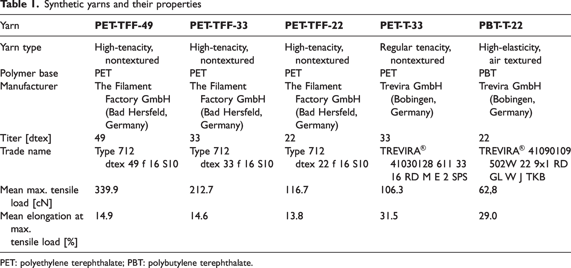
PET: polyethylene terephthalate; PBT: polybutylene terephthalate.
Methods
The feasibility of fabric production with the selected low-titer weaving materials for POF fabric manufacturing on a narrow fabric needle loom is assessed in weaving trials. For the produced specimens, the effect of yarn properties, thread densities and weave structure on fabric quality, geometry and lateral light intensity profiles of both fabric types are investigated.
Fabric production
The fabrics are produced at an ambient temperature of 21°C and a relative humidity (RH) of 60% with a narrow fabric needle loom of type ‘NH2 53 4/66 Z5’ (Jakob Müller AG Frick, Frick, Switzerland) running at 140 rpm and a shed closure angle of 320°. The POFs are used as monofilament warp yarn and the polyester yarns as weft yarn. The weaving machine is prepared for weaving from a creel with the POFs distributed onto individual spools. The warp tension is continually adjusted to the changing spool weights as the weaving process progresses. The weft yarn is unwound overhead with the weft yarn tension adjusted according to the weft material and weft density. A weft retaining hook is employed to enhance the homogeneity of the selvedge. Between the individual fabric specimens, the weft insertion is interrupted and the POFs are left bare, as shown in Figure 1. In this ’bundling section’ the POFs will later be bundled for light coupling. Once weft insertion is resumed, the first 5–10 mm of the fabric will show a higher level of irregularities and therefore is not used for testing (‘discard section’).
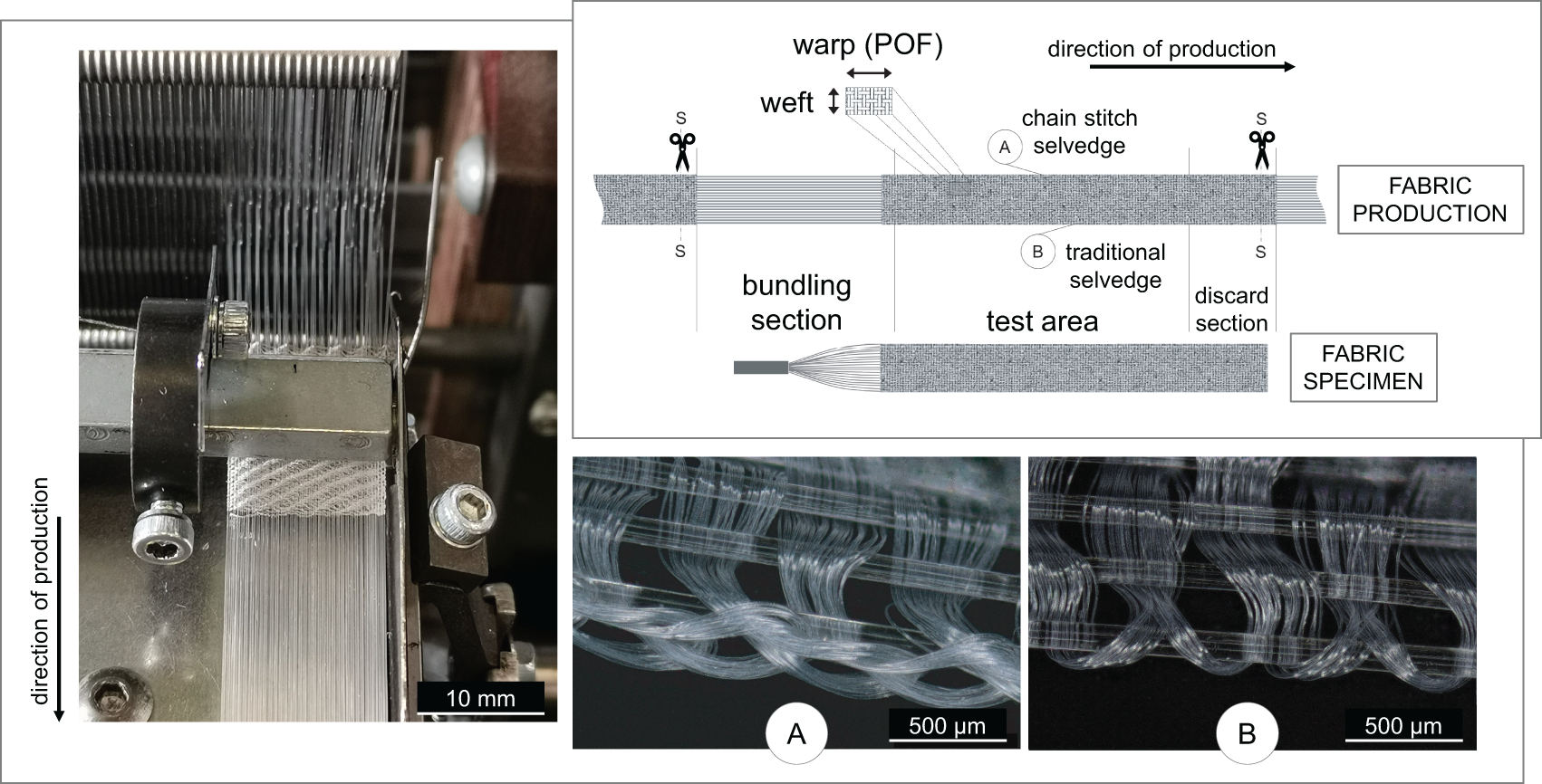
Manufacturing concept for the fabric production on the narrow fabric needle loom with (A) Chain stitch selvedge and the (B) traditional selvedge.
Fabric design: textile technology considerations
To ensure good fabric homogeneity as well as sufficient structural strength for the multiple specimen handling processes the edge design of the fabrics includes a chain stitch selvedge (A) as depicted in Figure 1. The opposite edge has a traditional selvedge (B).
For every weft yarn/POF combination, specimens with different weft yarn densities are produced. For this, the individual titer-dependent maximum weft density is iteratively determined during weaving as the upper process limit. For the materials used, distortion effects in the fabric become notable when the so-called weavability limit, that is, the maximum weft density, 45 is exceeded. Hence, the maximum weft density is visually identified as the highest weft density at which no such distortion occurs. Even though the weavability limit is slightly higher for twill than for plain weave, 46 the maximum weft density of the plain weave variants is used for the twill specimens as well. This allows for better comparability.
Specimens are manufactured at this maximum weft density as well as at the lowest weft density at which the fabrics still show a suitable structural strength for handling while also allowing for the fabric width to remain within the range of tolerance. For fabric type ‘a’, this lower limit weft density is identified at 50% of the maximum weft density while for fabric type ‘b’ these criteria are maxed out at 75% of the maximum weft density.
In addition, three even-sided weave patterns are examined: plain weave, 2/2 Z twill and 3/3 Z twill. The fabric edges of the twill specimens are executed in plain weave (as illustrated in Figure 2) to obtain an enhanced edge stability. The choice of even-sided weave patterns ensures that the fabrics possess the same illumination characteristics on both fabric sides as stipulated above. This also means that intensity measurements are only required for one fabric side. The structural difference between plain and twill weave is of interest regarding potential differences in both illumination characteristics and mechanical load-bearing behavior.
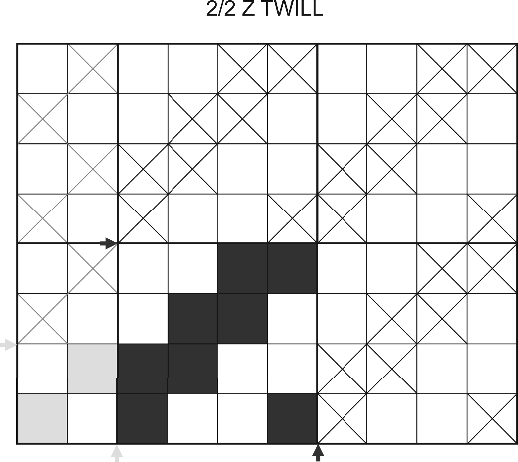
Weave plan for the specimens with 2/2 Z twill: the edges are executed in plain weave for warp yarns 1, 2, (n-1), and n.
While all fabric variations are produced in plain weave, the twill weaves are only explored for fabric type ‘a’ and applied in combination with the maximum weft density. When weaving in 3/3 twill, the warp tensions become highly irregular for the machine set-up used. This causes distortion in the fabrics produced. As a consequence, only one specimen batch is manufactured with this weave to evaluate the general effect on fabric thickness and fabric width. Table 2 provides an overview of the weaves and the weft densities with which the fabric specimens are produced. It should be noted that, as a result of the edge design, the weft yarn presents double within the fabric structure (also see microscopy image of the traditional selvedge (B) in Figure 1). This, as per convention, is not considered in the weft density specifications.
Weaves and weft densities
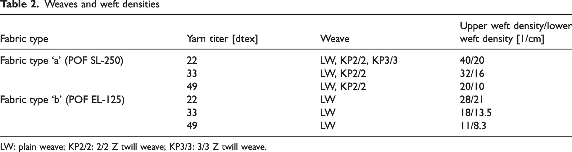
LW: plain weave; KP2/2: 2/2 Z twill weave; KP3/3: 3/3 Z twill weave.
Fabric design: adhesive technology considerations
The fabrics are designed for integration into adhesive joints. Adhesive joints are usually optimized for shear loading and thus designed as overlap geometries 12 for which the tensile lap shear strength is routinely tested in accordance with EN 1465:2009.47,48 As the tensile lap shear strength is sensitive to the overlap length of the joint, 12 EN 1465 specifies a narrow range of tolerance of ±0.25 mm (see Figure 3(a)) to ensure consistent mechanical properties. In the fabric design, the potential ability of the synthetic yarns to act in a load-bearing capacity is considered by placing them in the direction of load. This also minimizes the amount of expensive POF material required for fabric production. The fabric width then corresponds to the overlap length. As the results of this study will need to be verified by testing the actual performance of the fabrics in adhesive joints, the fabric geometry is chosen to accommodate these consecutive trials. Since the weft density is known to influence the fabric width, in order to investigate the effect of weft density modulation on the radiation properties of the fabrics, the range of tolerance for the fabric width derived from EN 1465 is extended to include widths of 12.5±0.50 mm.
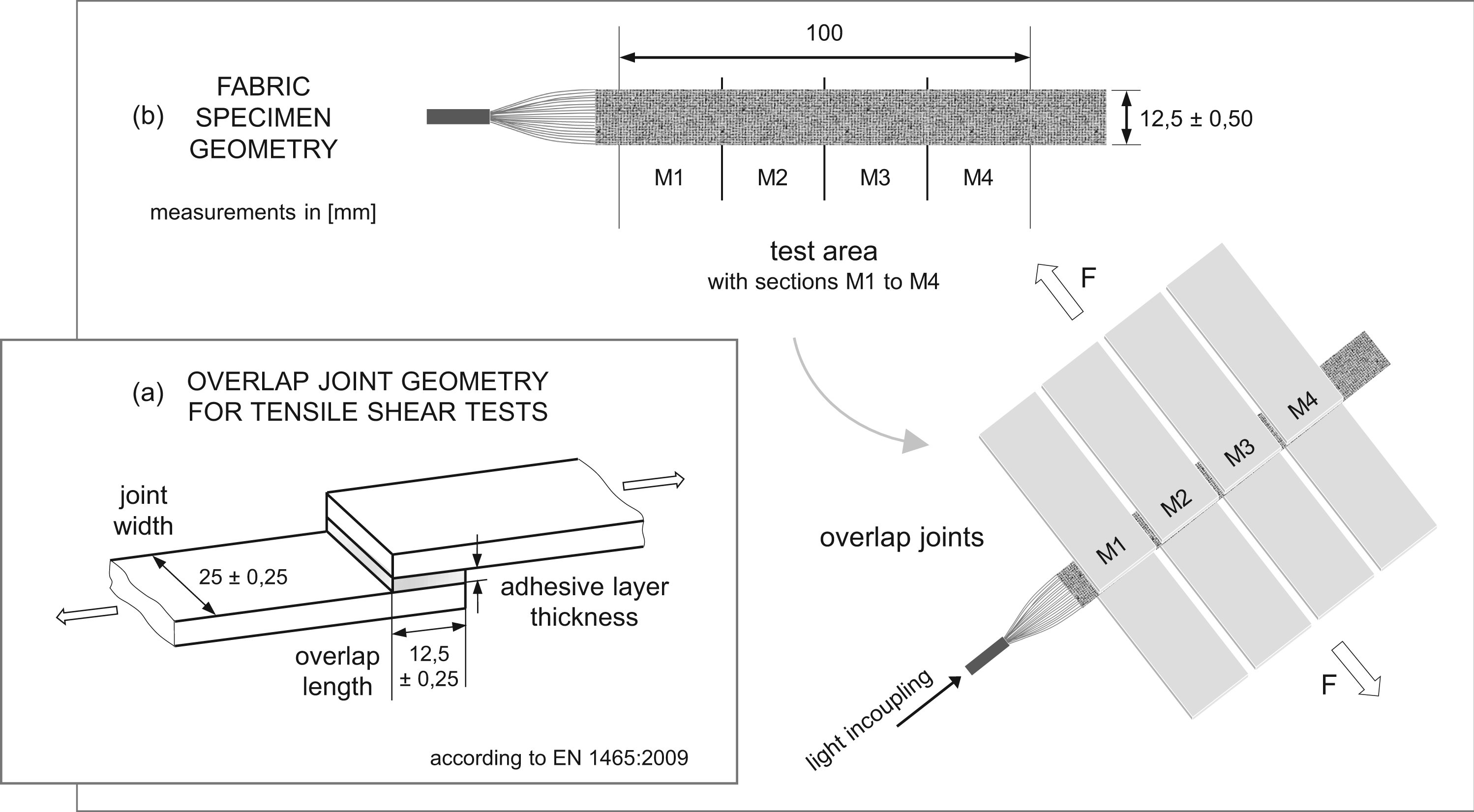
Fabric design taking into account: (a) the overlap joint geometry for tensile shear test specimens according to EN 1465:2009; and (b) resulting specimen geometry allowing for consecutive tensile shear testing.
For the definition of the basic testing concept for the specimens, the potential to correlate changes in lateral light intensity over fabric length with a corresponding tensile shear strength is taken into consideration. The specimen test area has a length of 100 mm which allows for the manufacturing of four overlap specimens as illustrated in Figure 3(b). These sections are denoted as test section M1 to M4.
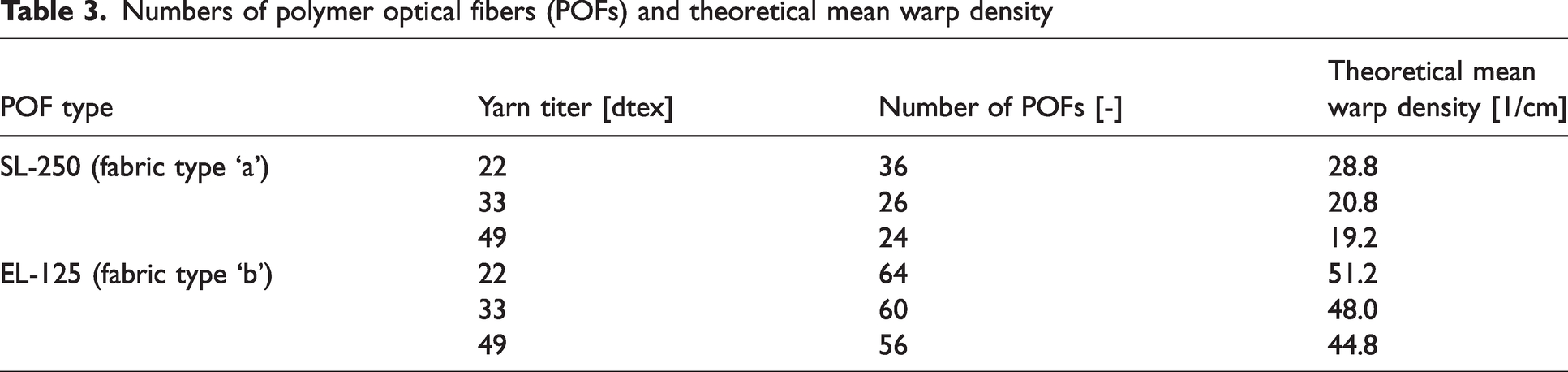
The number of POFs needed to produce fabric specimens at 12.5±0.50 mm varies with the weft yarn titer. Table 3 lists the number of POFs used for each material composition as well as the theoretical mean warp density using a fabric width of 12.5 mm as the reference value.
Numbers of polymer optical fibers (POFs) and theoretical mean warp density
Fabric design: experimental factors
A summarizing overview over the chosen fabric parameters is provided in Table 4. For each change in parameter three specimens are examined.
Experimental factors for fabric types ‘a’ and ‘b’
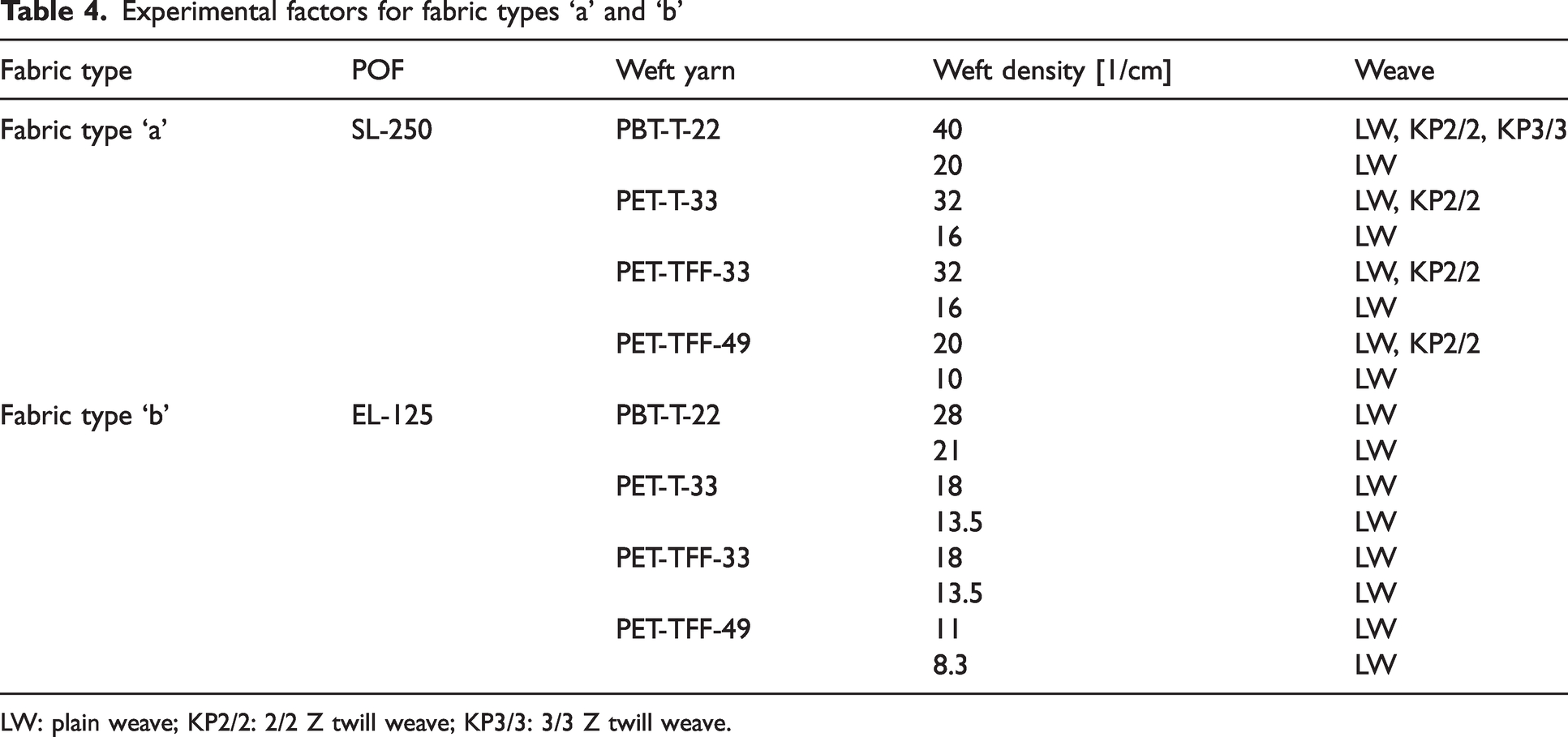
LW: plain weave; KP2/2: 2/2 Z twill weave; KP3/3: 3/3 Z twill weave.
Fabric preparation for intensity measurements
The POF ends of each fabric are bundled and embedded into an in-house manufactured aluminum connector using the epoxy resin system ‘5 Minute Epoxy Resin’ in combination with ‘Hardener S’ (R&G Faserverbundwerkstoffe GmbH, Waldenbuch, Germany). The in-coupling surface is wet-sanded to grit 5000 and polished with the polishing agent ‘ROTWEISS Acryl- und PLEXIGLAS Polierpaste’ (ROTWEISS Produkte, Wasserburg, Germany).
Test methods: fabric geometry
The fabric width is examined using the stereo microscope ‘Leica M205 C’ (Leica Microsystems GmbH, Wetzlar, Germany) at a magnification of 7.8× in combination with the camera system ‘MC170 HD’ and the analysis program ‘Leica Application Suite 5.0.3’. For each specimen five equally distributed measuring spots are examined, as illustrated in Figure 4(a). The same microscope is used to assess differences in fabric quality.
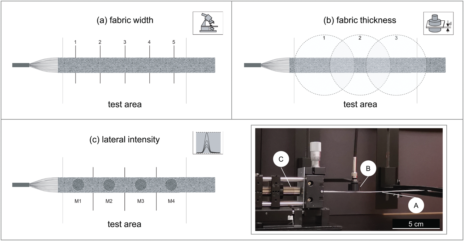
Testing schemes for: (a) fabric width; (b) fabric thickness; and (c) lateral light intensity measurements.
The fabric thickness is evaluated based on the standardized test method laid out by EN ISO 5084:1996. 49 Testing takes place at a load of 1±(0.01) kPa in normal climate (20.6°C, 65.75 (±.25)% RH) after conditioning the fabrics for 24 h. In deviation from EN ISO 5084, as Figure 4(b) depicts, there are three measurements with overlapping test-areas taken per specimen. Moreover, taking into account that the presser-foot has a diameter of 50.5 (±0.2) mm while the fabric width is expected to range at 12.5 (±0.5) mm, the fabric edges are likely to influence the thickness results.
Test methods: Lateral light intensity
To determine the specimens’ intensity profiles over the fabric length, the discrete intensity spectra at each section M1 to M4 of the specimens are recorded using the spectrometer ‘BLACK-Comet (model C)’ and the software ‘SpectraWiz v5.33’, both by StellarNet Inc. (Tampa, FL, USA). The exposition time is set at 1000 ms for fabric type ‘a’ and 700 ms for type ‘b’. The open-access software ‘Spectragryph 1.2.15’ is used for processing of the spectral data.
Figure 4(c) illustrates the testing scheme (left) and shows the test set-up (right) with a mounted fabric specimen (A). Measurements take place in a darkened room. The specimens are mounted such that they are suspended in the air with the spectrometer detector head (B) placed at 1 mm above the fabric. The light source used (C) is the ‘DELOLUX 50’ with lamp head ‘DELOLUX 50 × 1’ and lens ‘L1’ by DELO Industrie Klebstoffe GmbH & Co., KGaA (Windach, Germany). This is a regular spot lamp used for UV curing technology. It is operated at 100% light output and has a nominal peak wavelength of 400 nm.
Ten intensity spectra are recorded for each measuring section and processed into an averaged spectrum. From this averaged spectrum the effective lateral light intensity is obtained by integrating over the wavelength range at which excitation of the photoinitiators in the UV adhesive would take place in bonding tests. The relevant wavelength range of 330–420 nm is derived from the typical absorption spectrum of diphenyl(2,4,6-trimethylbenzoyl)phosphine oxide (TPO) at 0.1% (in acetonitrile), 50 while also considering that the recorded spectra show a lower emission limit of the light source/fabric combinations at around 330 nm. TPO is a common photoinitiator and is also used in the UV adhesive ‘LOCTITE AA 3494’ by Henkel AG & Co., KGaA (Düsseldorf, Germany) at a minimum concentration of 0.1%. 51 This UV acrylate has shown the most promising results in preliminary tests (also see Seewald et al.) 42 and is therefore the most likely candidate of choice for consecutive bonding trials.
Results and discussion
In this section, the results of the weaving trials and the fabric characterization are presented and discussed. For this purpose, the specimens are labelled following the nomenclature:
[POF]-[weft yarn]-[weave]-[weft yarn density]
Following this rule, a specimen named SL-250-PBT-T-22-LW-40 would be woven using POF type SL-250 and weft yarn PBT-T-22 at plain weave and a weft density of 40 1/cm.
Fabric production
The weaving trials showed that POF fabric production with low-titer materials on a narrow fabric needle loom is generally feasible: Both POF types were processable. However, for the high-tenacity, nontextured weft yarn PET-TFF-22 with 22 dtex no weaving machine setting was found to prevent frequent yarn breakage – making specimen manufacturing with this yarn impossible. For this high-tenacity yarn type, the feasibility limit is evidently reached at 33 dtex (PET-TFF-33), although PET-TFF-22 might still be weavable on a shuttle weaving loom which exerts a lower transverse load on the weft yarn. At the same time, the air textured 22 dtex yarn PBT-T-22 did not suffer from yarn breakage – which can be attributed to its high elasticity – and the production of POF fabrics with this yarn was successful. Consequently, it could be proved that even at the commercial limit of 22 dtex, polyester yarn can be used for POF fabric production on a narrow fabric needle loom, if the elasticity of the yarn is taken into consideration.
Fabric geometry
Fabric thickness
Figure 5 shows the results for the fabric thickness for fabric type ‘a’ and ‘b’ according to weft yarn and weft density. No trend along the fabric length could be identified. For fabric type ‘b’ all specimen thicknesses remain below the threshold of 300 µm. While for fabric type ‘b’ most specimens do not meet this target thickness, for all specimens woven with plain weave the thicknesses stay between 0.3 and 0.4 mm. The specimens with twill weave generally exhibit a higher fabric thickness than the fabrics with plain weave at the same weft yarn density. This adverse effect on the fabric thickness is even more pronounced for long floats, as the comparison between the specimen batches with 2/2 twill and 3/3 twill for PBT-T-22 indicates.
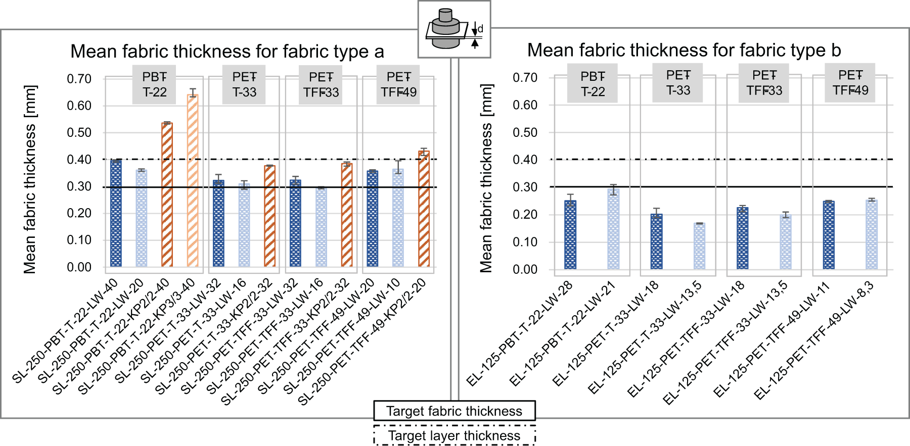
Mean fabric thickness for fabric types ‘a’ and ‘b’.
During the bonding process as part of the manufacturing process typically higher pressures would be exerted on the fabrics than the pressure applied in accordance with EN ISO 5084 during the thickness test. Even for the fabrics with low compressibility, this would potentially lead to flattening of the chain-stitch selvedge. Taking this into account, a definitive assessment of the suitability for use in adhesive joints for the fabrics of fabric type ‘b’ has to take place in bonding tests. The low test pressure also accounts for the fact that for weft yarn PBT-T-22 the fabric thicknesses, despite its very small titer of 22 dtex, are higher than for the 33-dtex yarns. This is because of the textured structure of PBT-T-22. However, this fiber structure potentially also causes high compressibility for these fabrics under the pressures exerted during the bonding process. As the mechanical performance of composite materials with twill weaves is generally considered better than with plain weaves, 52 tensile shear tests would also allow for an evaluation of the trade-off between this beneficial property and the negative effect of elevated joint thicknesses.
Fabric width
The results for the mean fabric width are depicted in Figure 7 against the ranges of tolerance for fabric width and adhesive overlap joint length. The raw data do not show a trend over the fabric length. The absolute deviation for each specimen batch remains with a maximum of 0.47 mm within the tolerance interval of 0.50 mm (or ±0.25 mm) for variation in adhesive joint specimen overlap length given by EN 1465. Consequently, it is generally feasible to produce overlap joint geometries fully conforming with EN 1465, if the fabrics are produced at constant weft density.
For all weft yarns, the fabric width decreases with the weft density. As predicted, for most POF/weft yarn combinations, the results indicate that, if the weft density is varied, the range of tolerance for overlap joints according to EN 1465 is largely exceeded. The extended range for the fabric width of 12±0.50 mm is mostly met by the specimens with the nontextured yarns (PET-T-33, PET-TFF-33 and PET-TFF-49) though. When it is not met (type ‘a’: PET-TFF-49), the differences in mean width between upper and lower weft density are below 1.0 mm (or ±0.50 mm). This indicates that, for these specimen types, the target width range can be met through adjustment of the machine settings during production. Therefore, further exploration of the approach of gradual modulation of the weft density potentially to enhance the homogeneity of the lateral light emission over the fabric length is an option for all nontextured yarns used.
In contrast, the results for the specimens produced with the air textured weft yarn PBT-T-22 show differences in mean fabric width of more than 1.0 mm between upper and lower weft density. In light of the tight geometric requirements, modulation of the weft density would likely not be applicable over the whole of the weft density ranges examined here. The results also reveal that the mean fabric widths for this yarn on the whole lie noticeably below the target width range, even though test measurements during production confirmed widths within the target range. This points to shrinkage during storage as an effect of the highly elastic textured structure of this yarn. Figure 6 illustrates the high potential for yarn contraction once the weaving tensions are gone. The fabric shrinkage needs to be considered from the outset when working with this yarn type.
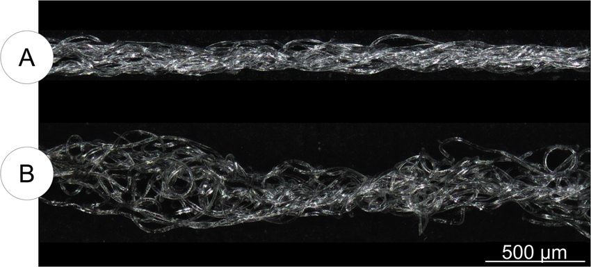
PBT-T-22 under tension (A) and in a relaxed state (B).
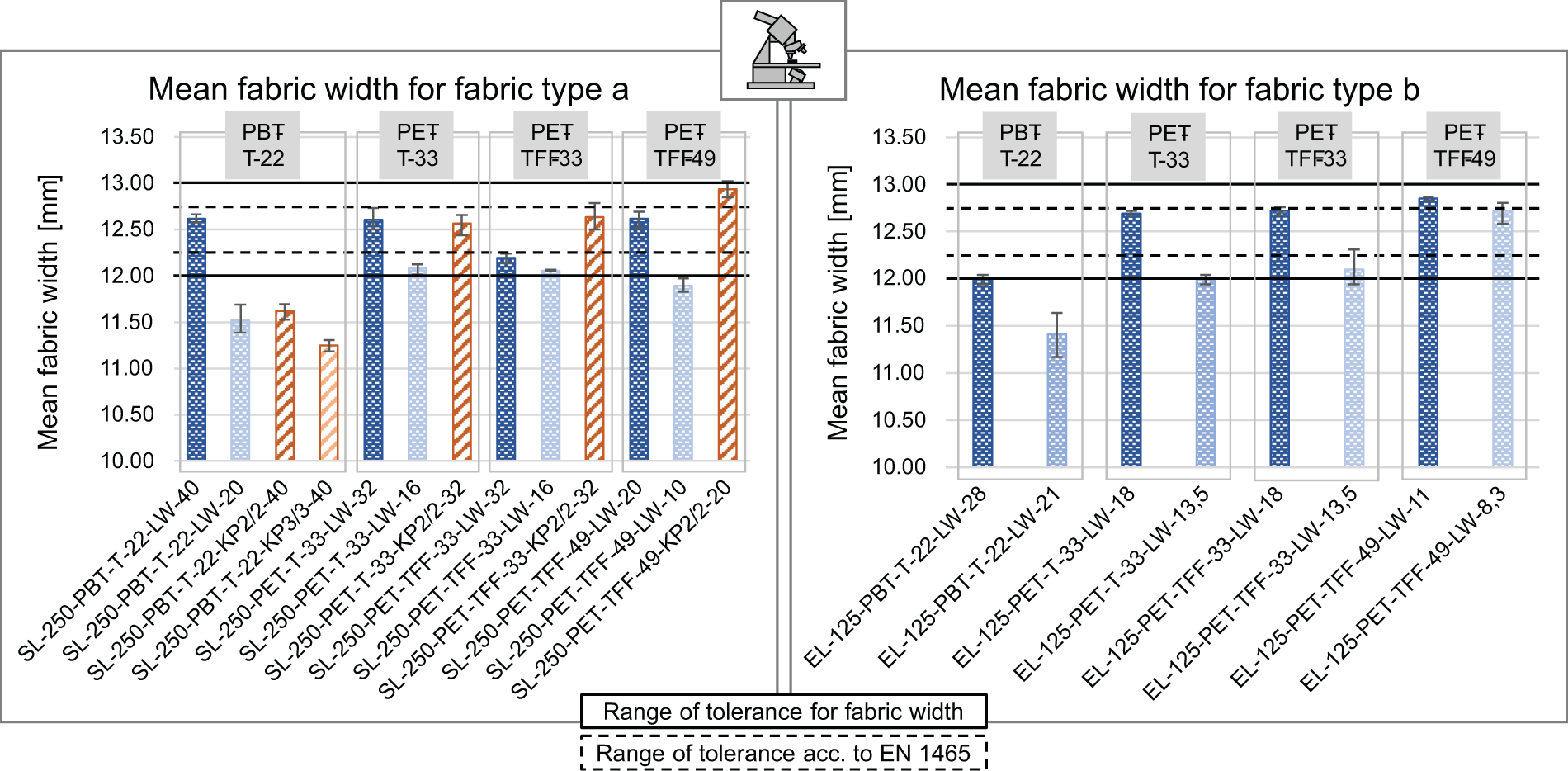
Mean fabric width for fabric types ‘a’ and ‘b’.
The effect of the weave on the fabric width does not follow a consistent trend. However, it can be connected to the elasticity characteristics of the weft yarn – resulting in decreased widths for twill weaves for yarn with high elasticity (such as PBT-T-22) and in increased widths for yarns with low elasticity (PET-TFF-33 and PET-TFF-49).
Fabric quality
The microscopy assessment of the fabrics exposes inhomogeneities in the fabric structure. These result from the limited flexibility in thread tension management during weaving, which ultimately is a consequence of working with materials near the boundary of weavability. Both fabric types show irregularities in warp thread distribution over the fabric width. Consequently, only a qualitative evaluation of the lateral light intensity based on warp density is possible (see Table 3 for theoretical warp densities). For fabric type ‘a’, the warp density around the traditional selvedge is lower than in the central area of the fabric (Figure 8(A)). Moreover, it is increased around the chain stitch selvedge. For fabric type ‘b’, the warp density in both selvedge areas is reduced compared with the central area (Figure 8(B)). These inhomogeneities also indicate differences in weft yarn tension between the central area and the selvedge areas, possibly causing lower/higher undulation of the POFs in the selvedge area. This presumption is supported by Figure 8(C), which shows a specimen of fabric type ‘a’ woven with PBT-T-22. The curly textured structure is more pronounced in the area near the selvedge (ii) than in the central area (i). This signals a lower weft yarn tension for area (ii). The fabrics produced with weft yarn type PBT-T-22 benefit from the fabric shrinkage identified above, in that they generally show the most equal POF distribution over the fabric width. However, the resulting narrow structure is potentially disadvantageous with regard to the impregnability by the adhesive matrix.
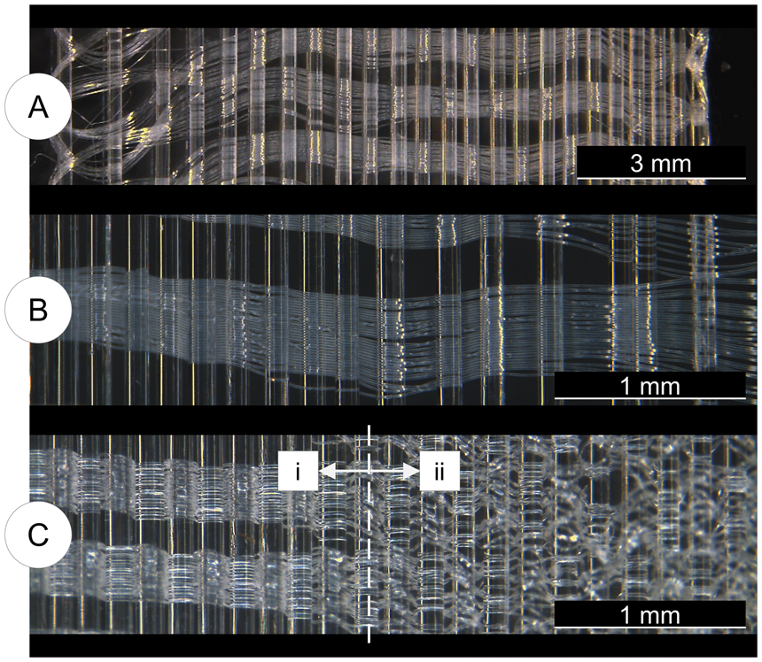
Inhomogeneities in warp yarn distribution over the fabric width for fabric type ‘a’ (A) and fabric type ‘b’ (B); (C): Pronounced weft yarn curls in the selvedge area (ii) as opposed to the central area (i).
To evaluate whether the inhomogeneities in POF distribution have a notable effect on the lateral light intensity profile over the fabric width, a luminosity camera could be used. The effect on the curing homogeneity would need to be assessed in bonding trials. Warp tension management could be further optimized by using an automated warp tension system for fabric production.
Lateral light intensity
The results for the mean effective light intensities over the fabric length are displayed in Figure 9. All fabric variants show an intensity decrease over the fabric length. For fabric type ‘a’, all specimens demonstrate a similar intensity profile irrespective of weft density (see Figure 9(a) and (b)) and weave (see Figure 9(a) and (c)) with an average decrease of 39.4% (+3.9%/–2.5%). This implies that the undulation of the SE-POFs has no impact or no significant impact on light out-coupling in this fabric type.
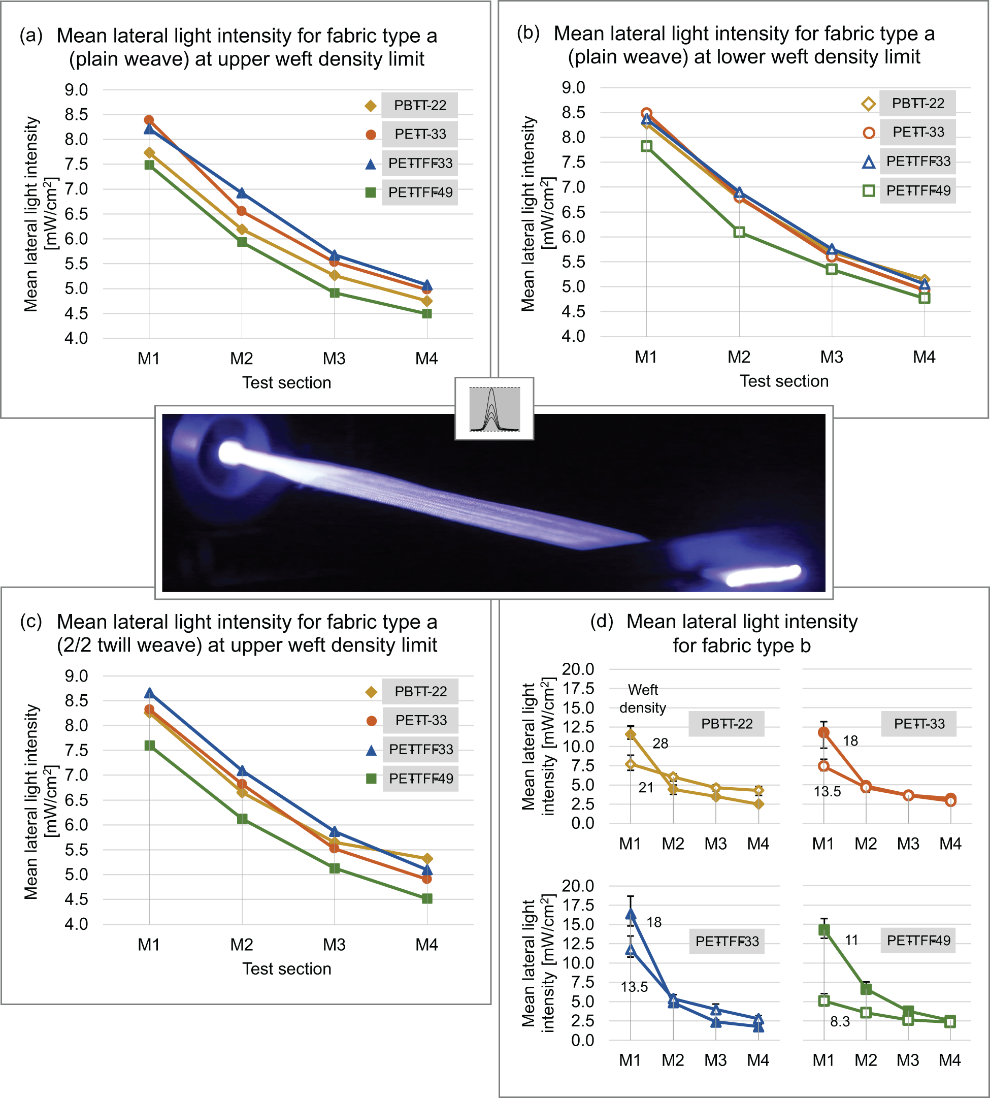
Mean (effective) lateral light intensity over fabric length for fabric types ‘a’ and ‘b’.
For all fabric parameters, the highest-performing intensity profiles for fabric type ‘a’ are achieved with the weft yarn types PET-T-33 and PET-TFF-33. The fabrics with PET-TFF-49 – which is the weft yarn with the highest titer – generally possess the lowest intensities for each section M1 to M4. This is presumably connected with their low warp density. At lower weft densities the lateral light intensities are slightly increased for all weft yarn types. This can be connected to two effects: at lower weft densities, less POF surface is covered which reduces the potential for light absorption and scattering by the weft yarn. In addition, as the fabrics have lower fabric widths at low weft densities, this indicates increased POF densities compared with the fabrics with high weft densities. The intensities for the fabrics with PBT-T-22, despite their high POF density, do not exceed the intensities for the 33 dtex yarns. A possible reason for this is that due to the yarn’s textured structure the amount of surface area covered by the yarn is larger. This is supported by the increased intensities in the fabrics with this yarn type, if twill weave is applied: Twill weave is characterized by higher float lengths. Overall, it can be concluded that, for fabric type ‘a’, fabrics manufactured with nontextured yarns at low titers and low weft densities exhibit the highest lateral light intensities. It needs to be pointed out, though, that the absolute deviation with an average of +0.38/–0.33 mW/cm2 is nearly in the same order of magnitude as the trends identified for variation in the weft yarn density and weave. For this fabric type, the effects of weft density modulation will be negligible. Instead, as a strategy to compensate the intensity loss over the fabric length, light coupling from both fabric ends can be explored. With this approach, for example for PET-T-33 at low weft density, theoretical effective intensities of 8.48 mW/cm2 or respective mean peak intensity values of 0.53 mW/cm2 and higher (depending on the fabric length chosen) are achievable. This is one order of magnitude higher than the fabrics presented by Quandt et al. 8 Considering the results of Cochrane et al., 33 this performance could be elevated further by substituting the light-emitting diode (LED) light source for a high-powered laser diode.
The intensity characteristics of fabric type ‘b’ (see Figure 9(d)) depend on the weft density. High initial intensities in M1 are exhibited at upper weft densities and lower initial intensity values are exhibited at lower weft densities. At the same time, the intensity loss over the fabric length is higher at high weft densities (up to 89.3% on average for PET-TFF-33) than at lower weft densities (lowest loss at 44.2% for PBT-T-22). As the primary out-coupling mechanism for this fabric type is the undulation of the POFs, this can be attributed to the small bending radii and high number of out-coupling points at high weft densities. The initial intensities for the high-tenacity yarns (PET-TFF-33 and PET-TFF-49) are significantly higher than for the other yarn types. This suggests that, in order to reach high intensities, the usage of weft yarns of lower elasticity has a beneficial impact on the warp crimp causing a high level of POF undulation. The dependency between lateral light intensity and weft density can potentially be exploited to manufacture low sidelight attenuation fabrics by applying a gradual modulation of the weft density over the fabric length. For this PET-TFF-33 and PET-TFF-49 are the most promising candidates. The fabrics with PET-TFF-49 show the widest intensity spectrum for weft density modulation, whereas the specimens woven with PET-TFF-33 exhibit the highest initial intensities.
For fabric type ‘b’, depending on the weft density chosen, significantly higher initial intensities are achievable than for fabric type ‘a’. However, almost all profiles of type ‘b’ drop down to lower intensities than exhibited by the fabrics of type ‘a’ in M4. Whether these lower intensity levels are disadvantageous with respect to the curing efficiency ultimately depends on the irradiation levels required for curing. To identify this critical threshold and allow for an ultimate assessment of the intensity levels, bonding tests are essential.
Conclusions and outlook
This paper outlines the design of extra thin POF fabrics for the curing of UV structural adhesive joints. It was shown that POF weaving for symmetrically side-emitting fabrics with a fabric thickness below 300 µm is feasible. In this context, fully exploiting the commercial titer limit for polyesters of 22 dtex on a narrow fabric needle loom is possible by choosing weft yarns with a high elasticity. The exclusive use of commercially available materials ensures minimal barriers for commercial upscaling.
Two design concepts with different out-coupling mechanisms (fabric type ‘a’: sidelight activation of SE-POFs; fabric type ‘b’: POF undulation within the fabric) were investigated with respect to the effect of different yarn types, weft densities and weaves on the fabrics’ geometry and lateral light emission characteristics. Design aspects covered the optimization of the specimen geometry to facilitate future use in bonding trials. The yarn selection included textured as well as nontextured weft yarn of regular or high tenacity with yarn titers of 22, 33 or 49 dtex. Based on the requirement of symmetrically illuminated fabric sides, the even-sided weave patterns plain, 2/2 Z twill and 3/3 Z twill weave were examined. Both design approaches showed promising results which merit further research.
For the application in adhesive joints, the fabrics are not only subject to restrictive requirements with respect to fabric height, but also to fabric width. It was found that, at constant weft density, the deviation in fabric width between specimens of the same materials and weave remains below ±0.25 mm. Thus, it is generally possible to produce overlap joint geometries from POF fabrics in compliance with the geometric requirements set out in EN 1465. Results also indicated that, for the nontextured weft yarns used, gradual modulation of the weft density can be explored as a method for fabrication of low sidelight attenuation fabrics. The lateral light intensity profiles suggest a good suitability of fabric type ‘b’ for this approach. For this fabric type, the lateral light intensity profiles distinctly show a dependency between lateral light intensity and weft density at high initial intensities – with the high-tenacity yarns PET-TFF-33 and PET-TFF-49 as the most promising candidates for gradual weft density modulation.
For fabric type ‘a’, the weft density only has a minor effect on the lateral light intensity. The intensity profiles imply that the undulation of the SE-POFs has no significant impact on lateral light emission. For this fabric type, it is recommended to investigate light coupling from both sides as a strategy to compensate intensity loss over the fabric length. The specimens manufactured with nontextured yarns at low titers (PET-T-33 and PET-TFF-33) and at low weft densities exhibit the highest lateral light intensities. In this context, the use of 2/2 twill weave instead of plain weave can be beneficial, for example, when working with textured weft yarn, like PBT-T-22. However, it needs to be taken into account that the fabrics with twill weave show higher fabric thicknesses which can have an adverse effect on the mechanical performance of the adhesive joint; 3/3 twill weave was found to be generally unsuitable for use in these extra thin POF fabrics, as distortion effects due to highly irregular warp tensions were observed during weaving.
Microscopy assessments of the fabric specimens revealed irregularities in warp density and weft yarn tension over the fabric width. In order to evaluate the effect on the illumination homogeneity over the fabric width, the use of a luminosity camera is proposed. In this context, POF fabrics with the air textured yarn type PBT-T-22 benefit from a high POF density caused by shrinkage in the weft direction. However, a potential negative impact on the impregnability by the adhesive will need to be investigated in bonding trials.
While the specimens of fabric type ‘a’ present with higher fabric thicknesses than those of fabric type ‘b’, the intensity loss over fabric length is also lower and the final intensities higher. No clear recommendation on which of the two concepts is more suitable for use in adhesive joints can be made at this stage. In order to understand the actual overall fabric performance and also assess mechanical performance and impregnability of the individual fabric variants in the adhesive joint, bonding trials are required.
Lap shear tests are also necessary to verify that the assumption made for the fabric thickness ensures competitive tensile shear strengths of the adhesive joints. Moreover, bonding trials are inevitable to identify the intensity levels required for curing. On this basis, an optimization of the fabric intensity profiles, as suggested above, in combination with the determination of the viable fabric length can take place.
Footnotes
Acknowledgements
The authors would like to thank the companies of the project accompanying committee for their constructive cooperation, provision of equipment and materials and for the inspiring discussions. Special acknowledgement is due to the Filament Factory GmbH (Bad Hersfeld, Germany), Trevira GmbH (Bobingen, Germany) and W. Barnet GmbH & Co. KG (Aachen, Germany) for supplying yarns for this project and to Henkel AG & Co. KGaA. (Dösseldorf, Germany) for providing adhesives as well as valuable expertise. The associated Master’s thesis “Bonding-on-Demand – Development of a sidelight-emitting POF fabric for the photoinitiated curing of adhesive joints with non-transparent substrates” was directly funded as part of the Speed Fund grants programme by Hans Hermann Voss Foundation (Wipperfürth, Germany) and supported through a stipend by Stiftung Industrieforschung (Essen, Germany).
Declaration of conflicting interests
The author(s) declared no potential conflicts of interest with respect to the research, authorship, and/or publication of this article.
Funding
The author(s) disclosed receipt of the following financial support for the research, authorship, and/or publication of this article: The results shown were obtained within the context of the Industrial Collective Research (“Industrielle Gemeinschaftsforschung”, IGF) projects [No. 20382N “FiberKleb - Use of polymer optical fibres for the curing of radiation-curing adhesives by radical polymerisation using non-transparent substrates”] and [No. 22722N “OpTexBond – Integration of fibre-optic textiles in bonded joints for photo-initiated curing of adhesives on intransparent joining partners”] of the “Forschungsvereinigung Schweißen und verwandte Verfahren e.V.” (Düsseldorf, Germany). Both projects were funded by the Federation of Industrial Research Associations (“Arbeitsgemeinschaft industrieller Forschungsvereinigungen”, AiF) within the framework of the programme for the promotion of IGF by the Federal Ministry for Economic Affairs and Climate Action (BMWK) on the basis of a resolution of the German Bundestag.