
Abstract
This paper introduces a novel extrusion process for manufacturing helical auxetic yarn (HAY). A range of semi-coextruded HAYs have been manufactured in a cost-effective, consistent and readily usable form. The semi-coextruded HAYs were compared to the conventional spun yarns in terms of tensile properties and auxetic behavior. The results show the presence of the auxetic effect in newly fabricated semi-coextruded HAYs. Similar to the traditional spun HAYs, the new HAYs are sensitive to parameters such as the initial wrap angle, the core/wrap diameter ratio and component moduli. Importantly, a few new manufacturing parameters have been identified for tailoring the auxetic behavior of the semi-coextruded HAYs. The semi-coextruded HAYs are auxetic when an instantaneous true Poisson’s ratio analysis method is applied. The semi-coextruded HAYs give a larger maximum negative Poisson’s ratio than the conventional HAYs due to the advantages of the pre-formed helical wrap structure.
Auxetic materials, known also as materials with a negative Poisson’s ratio, 1 have received significant scientific attention in the last two decades due to the possibility of enhanced material properties, such as fracture toughness, 2 indentation resistance, 3 low-velocity impact resistance 4 and a shear modulus. 5 Part of the auxetics family, auxetic textiles are attracting a lot of attention due to their potential applications in medical textiles, 6 anti-vibration gloves, 7 fiber-reinforced composites, 8 spacer fabrics 9 and protective clothing, 10 where they can enhance the energy absorption properties, the volume change and wear resistance. 11
The helical auxetic yarn (HAY) proposed first by Hook et al. 12 relies on the combination of two fibers: a low-modulus elastomeric core and a high-modulus wrap fiber. When a tensile load is applied, the structure exhibits a negative Poisson’s ratio. The HAY can be woven into technical textiles and has potential applications in safety restraints, body armor, 12 blast mitigation, filtration, 13 low-modulus composites 14 and high-modulus composites. 15 In addition, individual HAY can be utilized for applications such as dental floss, sutures and optical sensors. 16
To date, the auxetic performance of the HAY has been well investigated. Wright et al. 17 carried out a numerical study on the HAY using finite element analysis and they determined critical modeling criteria and design parameters for manufacturing the HAY; importantly, they indicated that the initial wrap angle was the most significant design variable. Sloan et al. 18 undertook the first detailed and experimental investigation of manufacturing and the auxetic performance of simple HAYs, fiber diameters, moduli, the initial geometry and the applied strain were identified as the key parameters for tailoring auxetic behavior of HAYs. Wright et al. 19 studied the auxetic effect of low-stiffness auxetic fabrics, which were manufactured by HAYs; they demonstrated that prepared auxetic fabrics would have potential applications in filtration and fluid transfer. Bhattacharya et al. 20 found that the core indentation effect (the wrap fiber embeds into the core fiber) would reduce the auxetic performance of the HAY; therefore, this phenomenon should be eliminated during the manufacturing process. Du et al.21,22 carried out theoretical and experimental studies to investigate the effect of different design parameters on the auxetic performance of HAY. Zhang et al. 23 fabricated a novel three-component auxetic structure based on a HAY and they indicated that the coating thickness was identified as a new design parameter for tailoring the auxetic effect. Zhang et al. 24 carried out a systematic study of HAYs using a wide range of fibers and they investigated the auxetic performance of HAYs by comparing the instantaneous true and engineering Poisson’s ratio; the results demonstrated that the instantaneous true Poisson’s ratio analysis was able to accurately show the instantaneous behavior of highly strain-dependent HAYs. In a recent dynamic thermo-mechanical and impact study of HAYs, 25 an optimal initial wrap angle of 27o has been found to give the best combination of stiffness, energy absorption and auxetic performance of HAYs.
All of above studies have used fiber spinning technology to create HAYs with different wrapping angles. This method has practical issues in accuracy and consistency of the wrap angle and component realignment, which affect the auxetic performance of the finished fabric (see Figure 1). In addition, large-scale manufacture of the HAY is impossible using a conventional yarn spinner as it is difficult to accurately maintain yarn tension and wrap angle and to permanently bind the two components together during the wrapping process
18
; the wrap fiber is simply guided onto the surface of the core fiber and adhesion is by virtue of torsional and/or frictional forces. Therefore, adhesion can be both minimal and variable, leading to poor conformance between components.
Example of poor conformance between the core and the wrap using conventional spinning technology.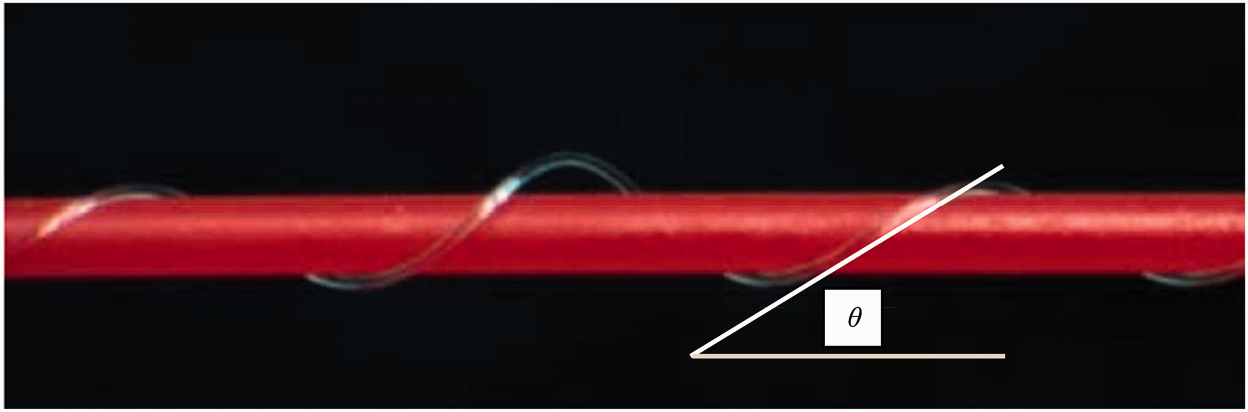
This study is the first to propose a different, novel fabrication route for HAYs with a consistent wrap angle at large scale using a unique semi-coextrusion process. Importantly, the semi-coextrusion process proposed in this paper opens the possibilities to an alternative manufacturing route for the HAY in industrial-scale quantities and at a quality for high-performance or ‘smart textiles’ applications.
Materials and method
Materials
Commercial monofilament polyethylene terephthalate (PET) core fiber was sourced from Monofil Technik. Elastollan® thermoplastic polyurethane (TPU) - CA85A granules (polyester-based TPU) were purchased from BASF for fabricating monofilament core fiber. Polypropylene (PP) – BH345MO and polyamide 6 (nylon 6) - Akulon® F136 – C1 granules were purchased from BOREALIS and DSM for manufacturing monofilament wrap fibers, respectively.
Manufacturing of monofilament fiber
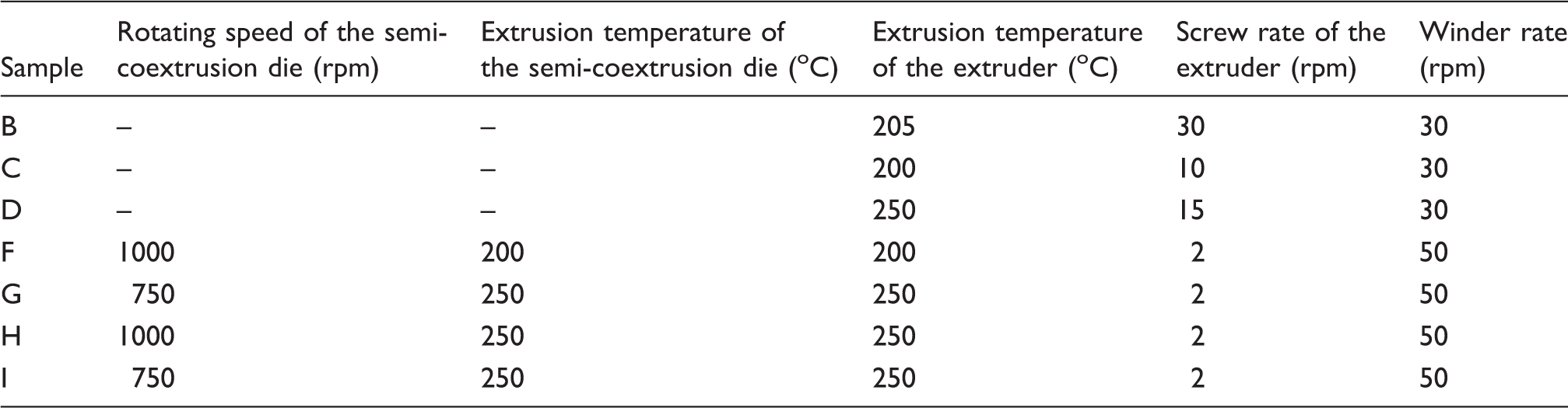
Key extrusion and semi-coextrusion parameters for fibers and yarns
Typical properties of fibers
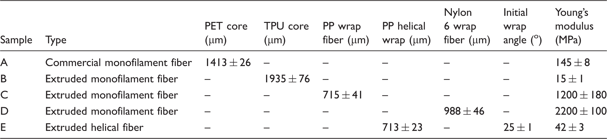
PET: polyethylene terephthalate; TPU: thermoplastic polyurethane; PP: polypropylene.
Manufacturing of semi-coextruded HAY
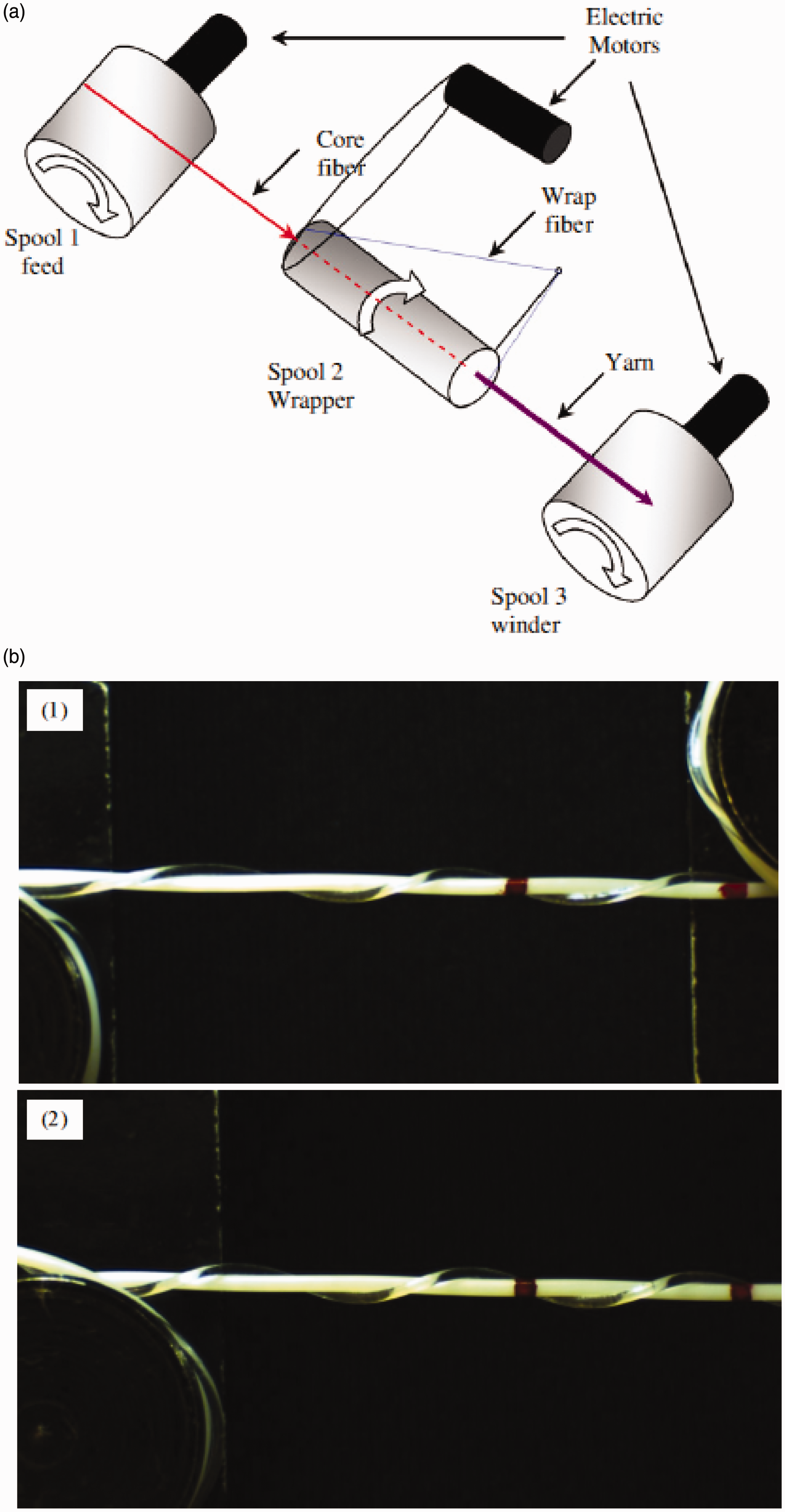
The semi-coextruded HAYs were manufactured using a bespoke semi-coextrusion system, bonding prefabricated core fiber with extruded wrap fiber in a semi-molten state. The semi-coextrusion wrapping mechanism is a three-stage process, as shown in Figure 2(a). (1) Commercial PET and manufactured TPU core fibers are drawn from a supply bobbin and fed to a rotating semi-coextrusion die. The core fibers remain intact as they travel through the center of the rotating die without melting. The center of the rotating die is insulated by polytetrafluoroethylene (PTFE), as shown in Figure 2(b); therefore, the center of the die is not heated and the core fibers are not exposed to heat. (2) The wrapping granules (PP or nylon 6) are extruded into the rotating die from the extruder at temperatures ranging from 200℃ to 250℃, depending on the material. The rotating die is optimized for each material depending on the viscosity of the wrapping material and the operating temperature of the wrapping material. The wrap fibers are extruded from the nozzle of the rotating die and wrapped helically around the core fibers. As the wrap fibers are hot extruded at the tip of the rotating die with a pre-formed helical structure, the two components bind permanently once the extruded wrap fibers are cooled in the air. (3) Manufactured semi-coextruded HAYs are collected by the winder.
Manufacturing of semi-coextruded helical auxetic yarn (HAY): (a) schematic of the semi-coextrusion of HAY; (b) sectional drawing of the semi-coextrusion die; (c) images of semi-coextruded HAYs: sample F (1), sample G (2), sample H (3) and sample I (4). PTFE: polytetrafluoroethylene.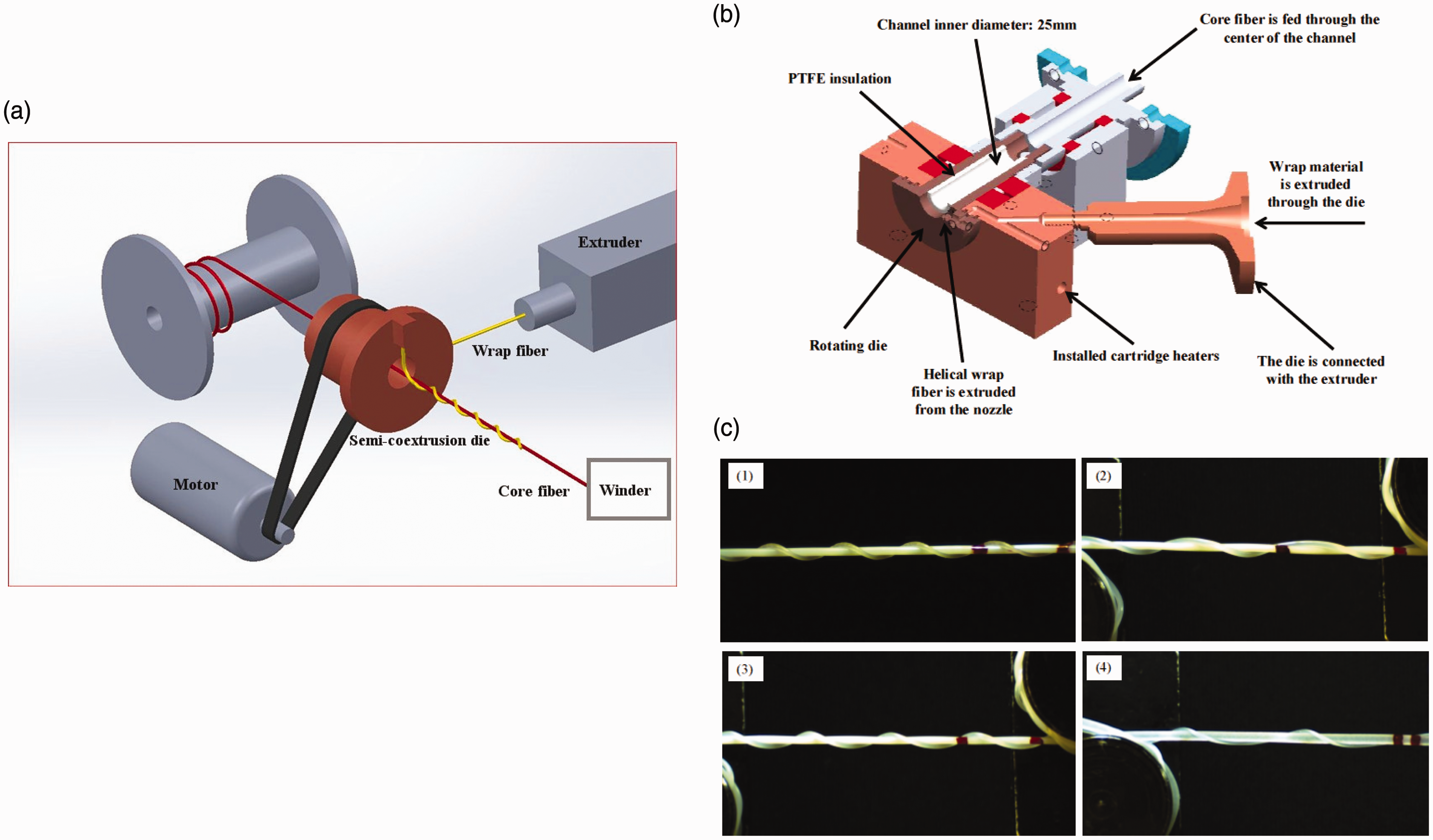
Figure 2(b) shows a sectional drawing of the semi-coextrusion die; it describes in detail how the wrapping materials (PP and nylon 6) are extruded and wrapped on the core fiber via the semi-coextrusion die. The heating and temperature setting of the semi-coextrusion die are controlled by two installed cartridge heaters and an external power meter, and the operating temperature range of the system is 0–300℃. Table 1 shows detailed extrusion temperatures for manufacturing semi-coextruded HAYs. The extruded wrap fibers are able to form a helix around the core fiber and thereby produce a repeatable and controlled wrapping angle at a constant tension; see Figure 2(c) for manufactured semi-coextruded HAYs.
Typical properties of conventional and semi-coextruded helical auxetic yarns (HAYs)
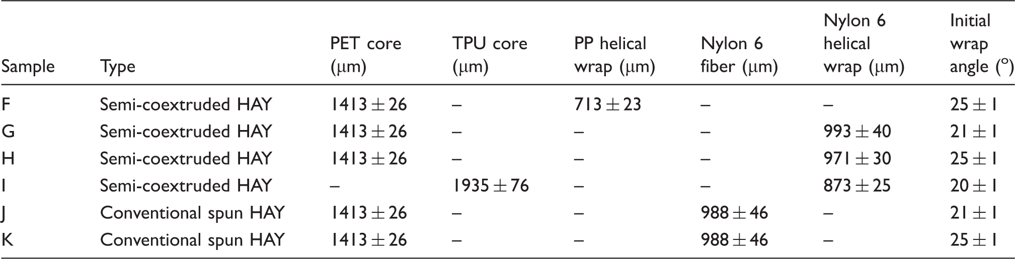
PET: polyethylene terephthalate; TPU: thermoplastic polyurethane; PP: polypropylene.
Manufacturing of conventional helical auxetic yarn (HAY): (a) schematic of the conventional yarn spinner (after Sloan et al. 18 ); (b) images of conventional HAYs: sample J (1) and sample K (2).
Tensile measurements and analysis of fibers and HAYs
The monofilament core, wrap fibers and HAYs in Tables 2 and 3 were prepared for mechanical testing according to ASTM D3822-07 – tensile properties of single textile fibers. 26 Tensile measurements of all the samples were carried out using a Lloyd instruments (www.ametektest.com) EZ 20 mechanical testing machine with a 500 N load cell at a crosshead speed of 5 mm min−1. Monofilament fibers, conventional HAYs and semi-coextruded HAYs of 200 mm length were taken from bulk spools of each sample batch, and a clamping gauge length of 80 mm was applied for all the samples. Three repeat measurements were conducted for each sample batch in order to prove whether these samples have stable mechanical properties and this novel semi-coextrusion system works in a repeatable manner.
A 4.9 MP digital camera (Edmund Optics EO-5012C USB) was utilized to capture images at pre-defined regular strain intervals during the tensile test; a detailed schematic of the test apparatus can be found in the previous study. 18 Acquired images were employed to calculate longitudinal and transverse sample strain. Sample length measurements for fibers and HAYs were obtained using a previously described image analysis method. 18 Sample width measurements for fibers and HAYs were obtained using MATLABR2011b to analyze the acquired images. 24
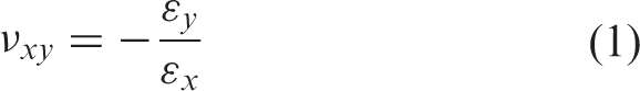
The engineering Poisson’s ratio for yarns was computed using measured engineering strains ɛ
y
and ɛ
x
As the HAY is a highly nonlinear material, it is not possible to adequately represent the instantaneous behavior of it by only using the engineering Poisson’s ratio. Therefore, it is necessary to utilize the instantaneous true strains and determine a strain-dependent Poisson’s ratio to accurately measure the instantaneous behavior of the HAY. Instantaneous true Poisson’s ratios for yarns were computed using obtained instantaneous true strains 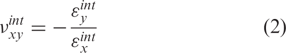
Results and discussion
Commercial and extruded fibers
The Young’s moduli of samples A–E were calculated using the small strain region (0.05–0.25%
27
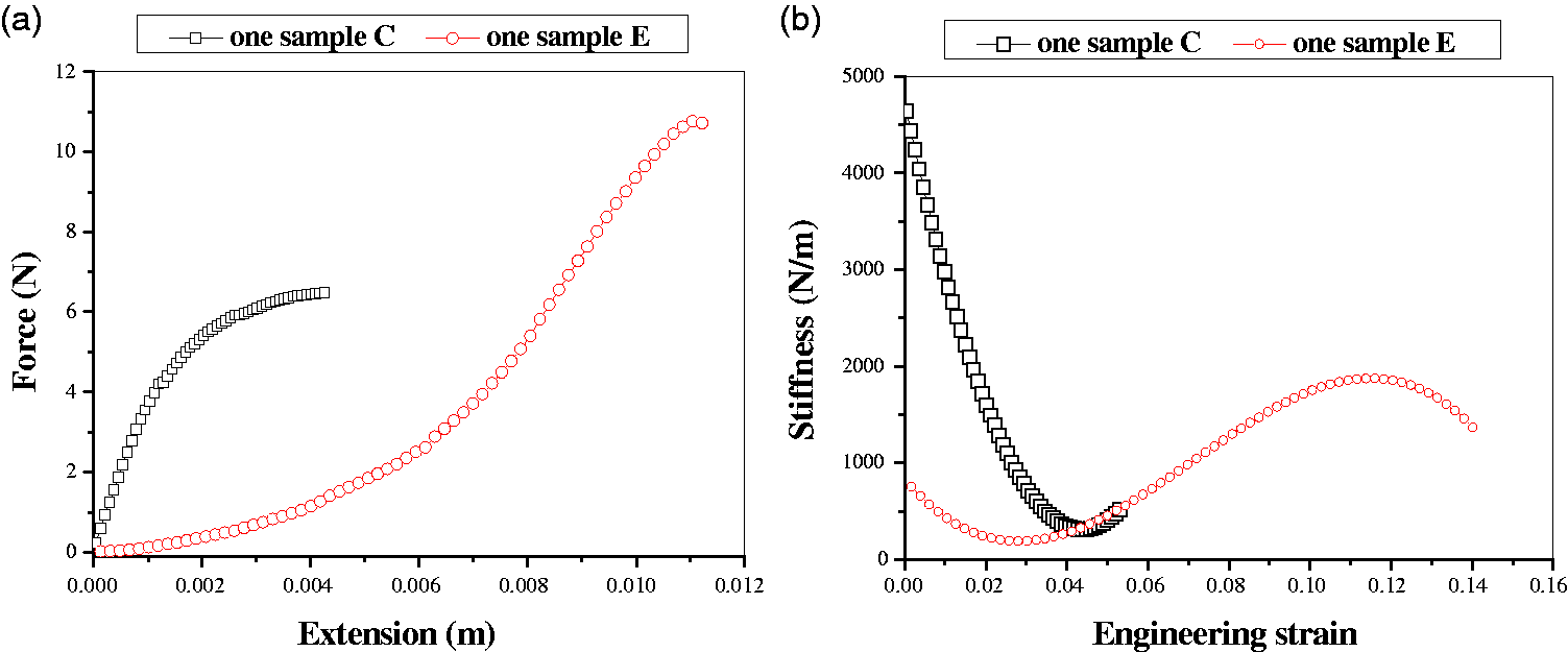
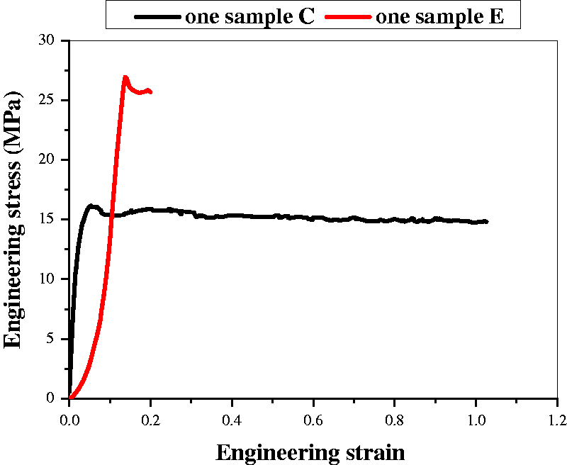
), as shown in Table 2. It is important to note that the cross-sectional area of sample E has been calculated as an elliptical cross-section. Figures 4(b) and (c) show extruded helical PP wrap at small deformation and failure, respectively. The helical structure of the wrap tends to go straight before failure. Force versus extension data for samples C and E and corresponding stiffnesses are shown in Figure 5. Figure 5 shows that the stiffness of extruded PP helical wrap is initially lower than that of PP fiber, followed by a gradual increase at a strain of 0.03, and finally becoming higher than that of PP fiber. Table 2 shows that the Young’s modulus of PP fiber is much higher than that of extruded PP helical wrap. Engineering stress strain data for samples C and E are plotted in Figure 6. It is clear that extruded PP helical wrap presents a higher tensile strength and lower elongation at break compared to PP fiber. Therefore, the results demonstrate that a pre-formed helical structure offers a better resistance to necking and fracture phenomena.
Image of extruded helical polypropylene wrap (sample E): (a) zero deformation; (b) small deformation; (c) failure. Force versus extension for samples C and E (a); stiffness versus strain for samples C and E (b). Stress–strain curve of samples C and E.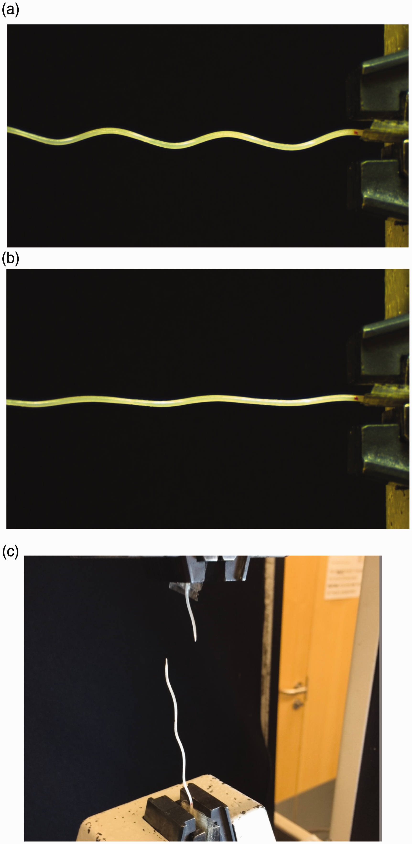
Semi-coextruded and conventional HAYs
Effect of component moduli and the core/wrap diameter ratio
Sample F was fabricated with PET core and PP wrap with an initial wrap angle of 25o. Figure 7(a) shows that the average sample width decreases as a function of average sample length then it starts to increase gradually until the end of the test. The engineering and instantaneous true ν of sample F were computed using Equations (1) and (2). The engineering ν is positive for sample F, indicating that the sample is non-auxetic. This behavior can be attributed to the widths of the sample, which are always smaller than the starting width of the sample, as shown in Figure 7(a). However, at strains above 0.1 a decrease can be observed in instantaneous true ν, which becomes negative, as shown in Figure 7(b). The zero-crossing of the Poisson’ ratio is due to the widths of the sample starting to increase instead of decrease. This is the onset of true auxetic behavior. After this critical point the instantaneous true ν will become increasingly negative until the end of the test. The PET core fiber shows a measured v in the range of 0.23–0.42 and it has small variation in v in comparison with the yarn. The HAY presents a different behavior in structural geometry as a function of strain. Therefore, the auxetic behavior of HAY is determined by the geometry and deformation of the material structure.
Poisson’s ratio analysis for sample F: (a) width versus length of sample F; (b) 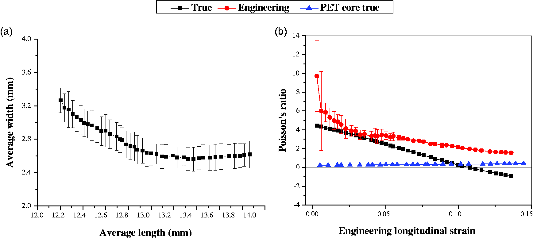
It has been shown previously that a higher wrap modulus gives a potentially higher negative yarn ν.
17
Therefore, sample H was manufactured with PET core and stiffer wrap than PP: nylon 6. Figure 8(a) shows that the average sample width decreases as a function of average sample length until very end of the test, followed by a slight increase. The engineering ν curve shows that the sample is not auxetic, as shown in Figure 8(b). However, the instantaneous true ν curve indicates that the sample becomes auxetic at strains above 0.2 due to the slight increase in sample width near the end of the test.
Poisson’s ratio analysis for sample H: (a) width versus length of sample H; (b) 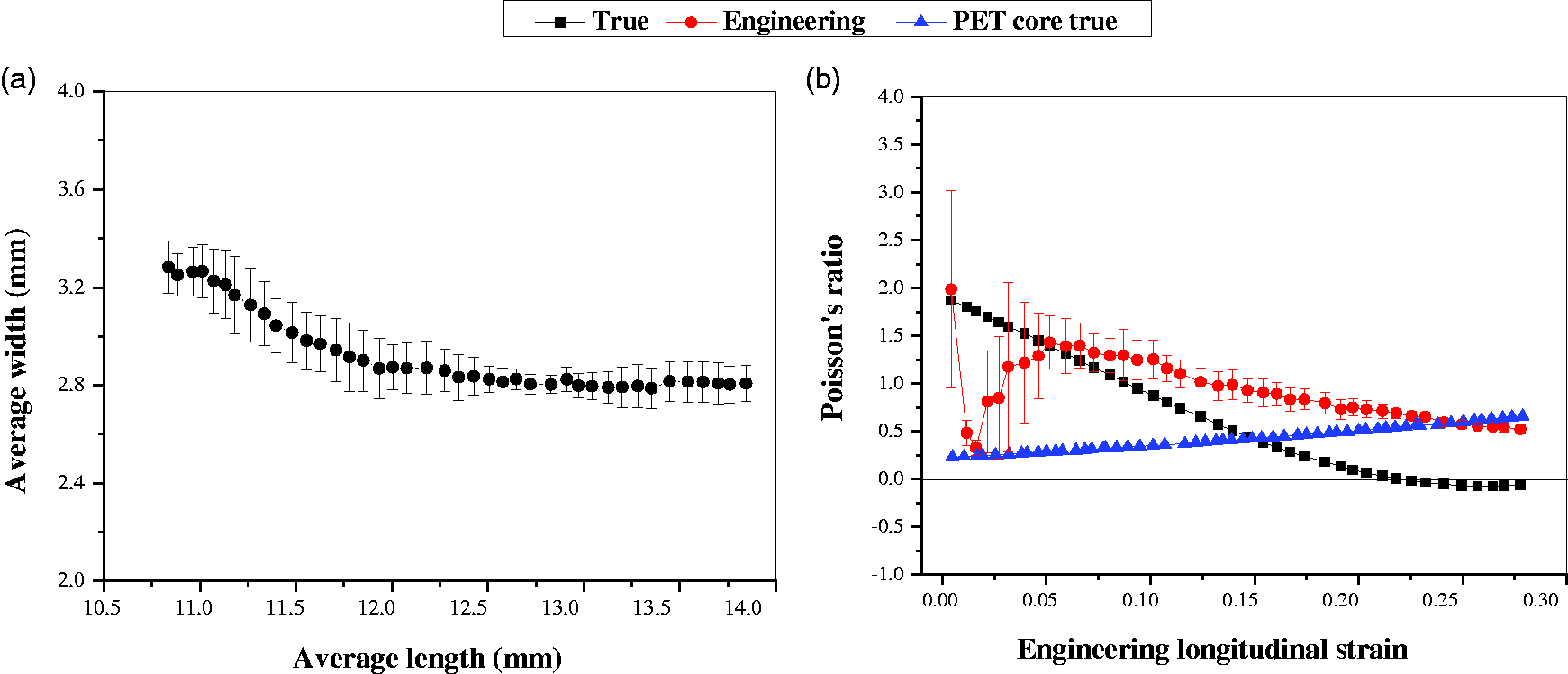
A low-modulus TPU core fiber was prepared to fabricate sample I in order to achieve a better auxetic effect compared to sample G. Samples I and G were manufactured with the same initial wrap angle but with different component moduli and core/wrap diameter ratios. Figure 9 shows the Poisson’s ratio analysis for sample I; it indicates that sample I shows a sharp decrease in average sample width followed by a sudden increase in magnitude to a point where the average sample width starts to decrease again. A large variation in sample dimension data can severely affect the Poisson’s ratio curve. Figure 9(b) shows the engineering ν of the sample decreases as a function of applied engineering longitudinal strain. The engineering ν maintains positive until the end of the test, and therefore the sample does not present engineering auxetic behavior. At strains below 0.13 a gradual increase in the instantaneous true ν for the sample can be observed, after which a sharp decrease in the instantaneous true ν is presented. The sharp decrease in the instantaneous true ν is attributed to the sharp increase of sample width, as shown in Figure 9(a), and this is the onset of true auxetic effect for the sample. The auxetic behavior of sample I continues further as the strain is applied and a maximum value of instantaneous true ν at –5.7 is obtained at the onset of the true auxetic effect. After this point the instantaneous true ν becomes decreasingly negative and at strains above 0.3 it turns into positive again due to the gradually decreased sample width near the end of the test.
Poisson’s ratio analysis for sample I: (a) width versus length of sample I; (b) 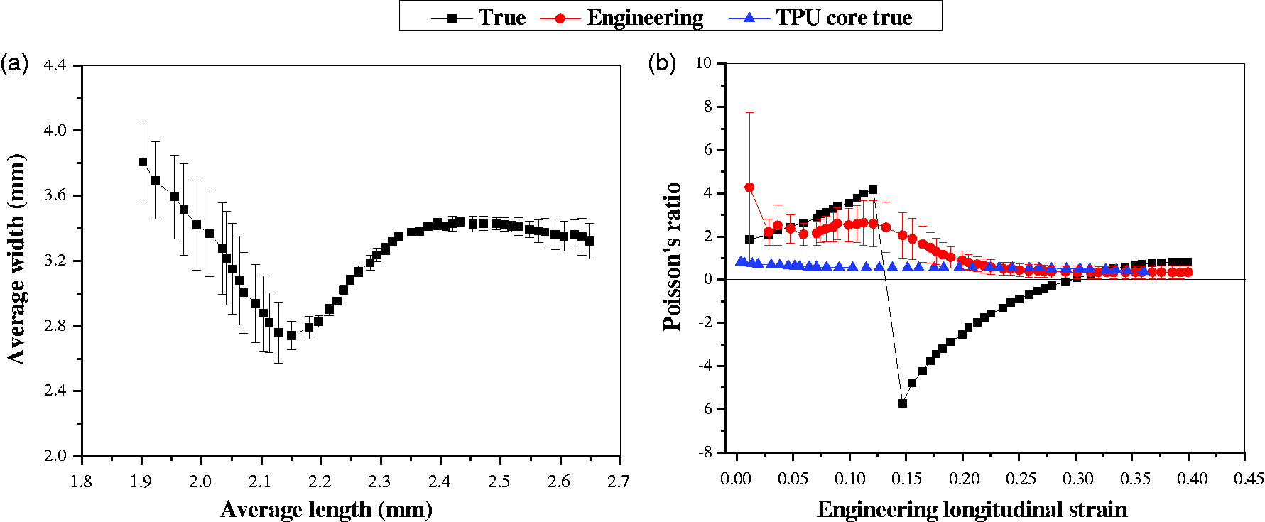
Figure 10 shows that semi-coextruded HAY fabricated with TPU core and nylon 6 wrap fibers (sample I) gives a better overall auxetic effect and larger maximum negative ν in comparison with sample G. The results agree well with previous studies for conventional HAYs,17,18,24 where a larger difference in component moduli and a higher core/wrap diameter ratio can produce a larger maximum negative Poisson’s ratio value and thereby a better auxetic performance.
Comparison of instantaneous true Poisson’s ratio analysis between samples G and I.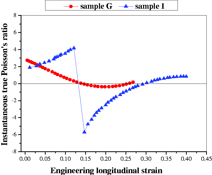
Effect of wrap angle
The initial wrap angle is the most significant design parameter, which will affect the auxetic performance of the yarn.
23
Sample G was manufactured with the same core and wrap fibers as sample H but with an initial wrap angle of 21o. Figure 11(a) shows that sample G has an initial decrease in average sample width followed by a gradual increase and remained almost constant near the end of test. The engineering ν curve in Figure 8(b) indicates that sample G is not auxetic as the engineering ν is positive throughout the test. However, the behavior of sample G can be divided into three strain-dependent phases using the instantaneous true ν curve (Figure 11(b)): in region I the sample has a positive ν; in region II the instantaneous true ν becomes negative at a strain of 0.15 and then reaches the maximum value of –0.38 at a strain of 0.2; in region III the instantaneous true ν turns into positive again at a strain of 0.25. The instantaneous behavior of the Poisson’s ratio in Figure 11(b) agrees well with the dimension data shown in Figure 11(a).
Poisson’s ratio analysis for sample G: (a) width versus length of sample G; (b) 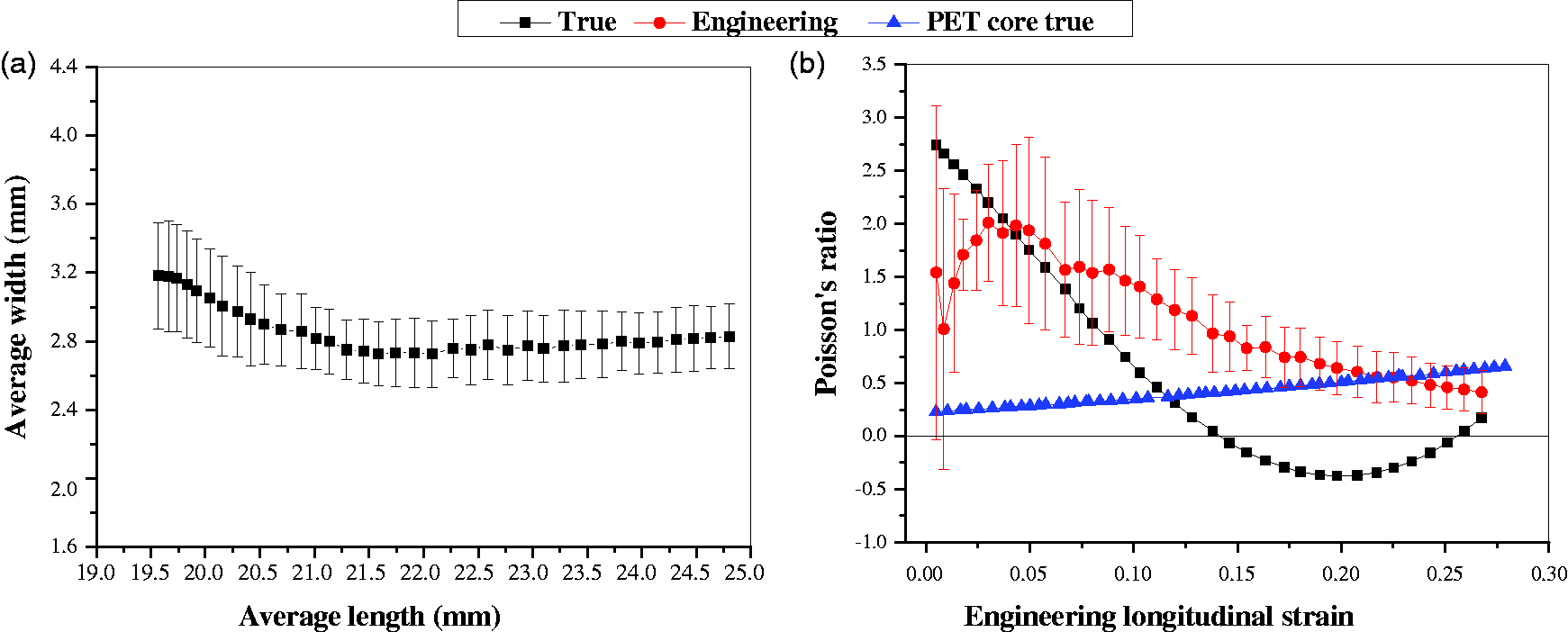
The effect of varying the initial wrap angle on the auxetic behavior of the semi-coextruded HAYs is shown in Figure 12. Figure 12 shows that sample G fabricated with PET core and nylon 6 wrap with a lower initial wrap angle can produce an earlier activation of the auxetic effect at a strain of 0.14 and a larger maximum negative Poisson’s ratio at −0.38 compared to sample H. This phenomenon can be attributed to a lower initial wrap angle leading to an earlier expansion of the sample after contraction. The true activation strain of sample H (0.22) is much larger that of sample G (0.14), as shown in Figure 12. The true activation strain is defined at which the sample width starts to increase. The results agree well with previous studies for conventional HAYs in terms of instantaneous true Poisson’s ratio analysis.17,24 It demonstrates that the design parameters for conventional HAYs can also be applied for semi-coextruded HAYs in practice.
Variation in wrap angle on auxetic performance of semi-coextruded helical auxetic yarns.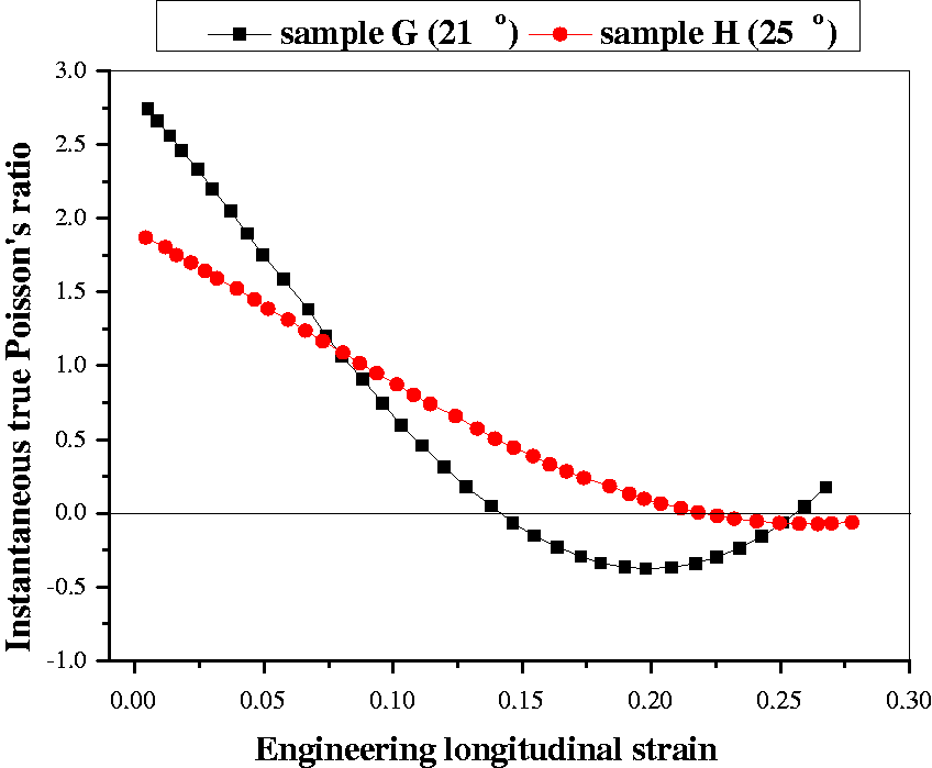
Comparison of semi-coextruded and conventional spun HAYs
Conventional HAY sample J was manufactured using a conventional yarn spinner and it was compared with semi-coextruded HAY (sample G), as shown Figure 13. Figure 13(a) show the stress–strain data for the conventional and semi-coextruded HAYs, and from this it can be observed they have similar behavior under tensile measurements. It demonstrates that the extrusion process has a small effect on the tensile properties of the yarn. Figure 13(b) shows that the instantaneous true ν of conventional HAY (sample J) is positive for the entire test, indicating that the sample is not auxetic. However, the semi-coextruded HAY (sample G) has negative instantaneous true ν in the strain range of 0.14–0.25 and the yarn is auxetic in that region. It is interesting to note that a large positive instantaneous true Poisson’s ratio is observed for sample K at low strain. This behavior can be attributed to the loose wrap fiber conforming to the core fiber at low strain, as the conventional HAY experiences poor conformance problem between the core and the wrap (see Figure 1).
Comparison of semi-coextruded helical auxetic yarn (HAY) (sample G) and conventional (sample J) spun HAY: (a) stress versus strain; (b) instantaneous true Poisson’s ratio versus strain.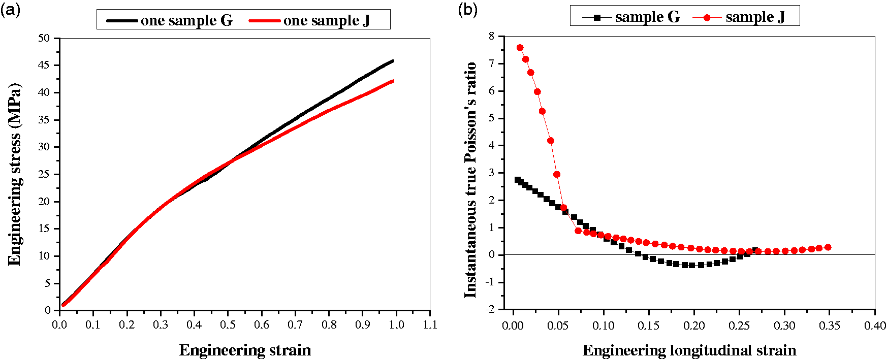
Conventional HAY sample K was manufactured in order to compare it with the semi-coextruded HAY sample H. Figure 14(a) indicates that samples H and K present similar behavior under tensile measurements. The semi-coextruded HAY (sample H) is auxetic while the conventional HAY (sample K) is non-auxetic, as shown in Figure 14(b. The instantaneous true ν of sample H turns into negative at strains above 0.2 and, after this true activation strain, the sample becomes auxetic. As demonstrated in Figure 4, a pre-formed helical wrap of the semi-coextruded HAY becomes stiffer than straight wrap fiber as the strain is applied. Therefore, HAYs manufactured with a pre-formed helical wrap structure can produce a better auxetic effect than conventional HAYs.
Comparison of semi-coextruded helical auxetic yarn (HAY) (sample H) and conventional (sample K) spun HAY: (a) stress versus strain; (b) instantaneous true Poisson’s ratio versus strain.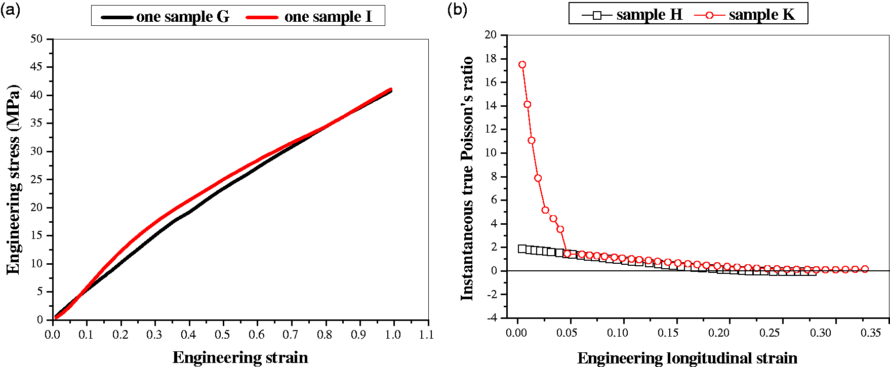
Conclusions
This paper proposes a novel method for large-scale, controlled manufacturing of HAYs. A series of HAYs have been successfully manufactured by using a bespoke semi-coextrusion process in a consistent and repeatable way. The work demonstrates that it is possible to manufacture the semi-coextruded HAY with a negative Poisson’s ratio in a consistent way.
As previously shown, the engineering Poisson’s ratio analysis is unreliable and misleading in practice for highly nonlinear materials, such as a HAY. Therefore, this work includes results of the instantaneous true Poisson’s ratio analysis and it accurately analyzed the instantaneous behavior of the semi-coextruded HAY.
The auxetic performance of the semi-coextruded HAY can be tailored using previously defined key parameters, such as component moduli, the core/wrap diameter ratio and the initial wrap angle. In addition, a few new manufacturing parameters have been identified for tailoring the auxetic behavior of the semi-coextruded HAY.
The semi-coextruded HAYs offer a larger maximum negative Poisson’s ratio and therefore a better auxetic performance than the conventional HAYs due to the advantages of pre-formed helical wrap fiber.
Footnotes
Acknowledgements
The authors would like to acknowledge their colleagues Yat-Tarng Shyng and the late Dave Baker for technical support.
Declaration of conflicting interests
The authors declared no potential conflicts of interest with respect to the research, authorship and/or publication of this article.
Funding
The authors disclosed receipt of the following financial support for the research, authorship, and/or publication of this article: This work is supported by the UK Engineering and Physical Sciences Research Council (EPSRC Grant No. EP/J004553/1).