
Abstract
Passive damping treatments using viscoelastic materials (VEMs) are widely applied as addon solutions to control the dynamic response of light structures. These surface treatments are simple, reliable, and can be optimized by using proper design rules and simulation tools. In this work, a new treatment configuration is proposed, simulated, and assessed, being compared with the most effective configuration currently used. The novelty resides in the VEM layer’s geometry, which in the proposed configuration assumes a waved shape. This waved shape is imposed to the viscoelastic layer due to indentations created in the inner faces of the host structure and the constraining layer. The results demonstrate that the wavy configuration, designated as corrugated viscoelastic layer (CVL), outperforms the typical damping treatments for relatively thick host structures and when using thick VEM layers. In addition, this new configuration reduces the stiffness decoupling effect due to the soft VEM layer, restoring the flexural stiffness of the original undamped structure.
1. Introduction
Dynamic response of structures is a relevant research field within some of the most important areas of application of lightweight and flexible structures, such as aerospace and automotive industries.
During the last decades, structures became lighter and flexible, taking advantage of new materials and novel production and assembling processes. The heavy timber and cast-iron structures have been replaced by light composites and metallic alloys, used to form lightweight structures assembled with adhesives and other efficient welding or joining technologies. Novel design strategies, like those based on artificial intelligence (AI)-assisted generative design techniques, promote the development of light and stiff structures that additive manufacturing processes can materialize.
Despite the considerable improvements in the structural field by adopting light and stiff materials, along with new manufacturing techniques, new shapes, and design trends, the dynamic response of those light structures nowadays assumes a vital role during the project stage. In fact, most of the valuable sources of damping were simply lost during this evolution of the structural field. Therefore, adding external forms of damping or other structural control strategies is currently mandatory to reduce the dynamic response of structures subject to external or inborn dynamic loading, thus reducing fatigue and premature collapse of the structures.
1.1. Viscoelastic damping treatments
Among the dynamic control strategies of structures, the passive damping treatments based on viscoelastic materials (VEMs)1,2 assume an important position when flexibility and weight of the structure are a critical issue. Basically, viscoelastic damping treatments act as energy dissipation mechanisms than can remove an important part of the vibration energy of the system as heat.
Figure 1 briefly represents the working principle of passive damping treatments using VEMs. In a closed system, without damping, the structure motion during vibration results from a continuous and cyclic transformation between the structure’s deformation energy (potential energy) and kinetic energy, and vice versa. Without any dissipation mechanism (or, in practice, with negligible dissipation), this cyclic energy transformation can sustain even for low levels of external dynamic loading (external energy source). More importantly, if the structure is excited at any of its natural frequencies, particularly in the fundamental natural frequency, low levels of loading can induce significant levels of deformation (high levels of deformation energy) that consequently will be converted to high levels of kinetic energy and a resonance phenomenon arises. On the contrary, if some form of energy dissipation is placed inside this cyclic energy transfer system, a damping mechanism is thus created and able to control the dynamic response of the structure. For such purpose, thin layers of VEMs can be simply attached to the structure’s surface, which are cyclically deformed due to the deformation of the host structure under vibration.
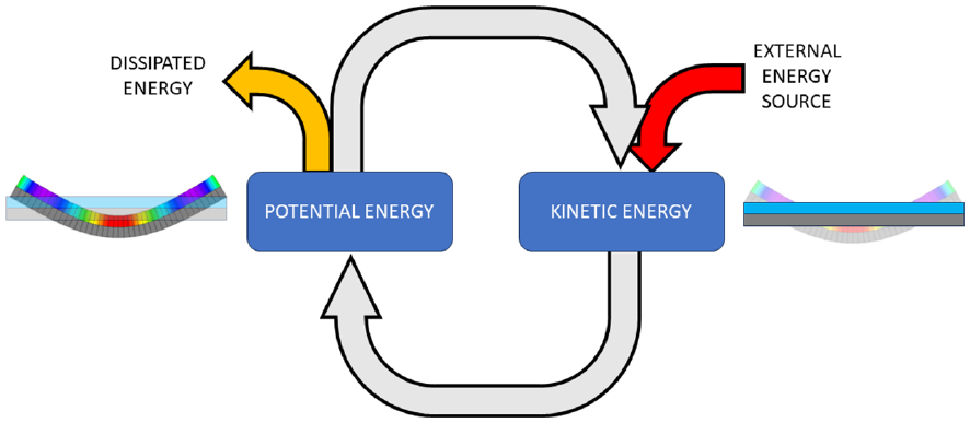
Cyclic energy transformation during the vibration motion of a structure.
VEMs for damping applications present a high loss factor value, typically between 0.5 and 0.9, within a specific and narrow frequency or temperature range.1,2 That means that such viscoelastic layers can dissipate between 50% and 90% of the deformation energy that were able to store during the deformation imposed on the host structure during vibration. Therefore, the design of these damping treatments aims to maximize the amount of deformation energy stored inside the viscoelastic layer.
Viscoelastic damping treatments have been successfully used in the aerospace, aeronautic and automotive industries for the last decades, and a considerable research effort continues to be applied in this passive damping mechanism.3–5 Most of this recent research aims at the development of more efficient materials able to sustain high levels of loss factor over broad ranges of frequency and temperature,6,7 and the design of treatment configurations able to maximize the amount of deformation energy transferred and stored inside the viscoelastic layer.8–10 This work was related to the latter research effort and explores different spatial configurations of the viscoelastic layer toward the maximization of stored and dissipated energy.
Viscoelastic damping treatments are often applied following two different approaches: the free layer (Figure 2(a)) and the constrained layer (Figure 2(b)) configuration.
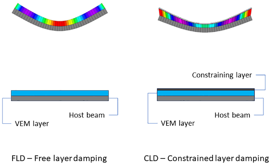
Viscoelastic damping treatment configurations: (a) free layer and (b) constrained layer.
The free-layer configuration is straightforward to apply and design but requires thick viscoelastic layers, often in the same order of magnitude of host structure’s thickness. Therefore, this configuration is usually neglected when the final weight of the structure is a critical issue, which typically occurs in those industries listed above. On the contrary, in the constrained layer configuration, the viscoelastic layer is very thin and covered by a stiff and thin layer made from an aluminum or stainless-steel foil. Although other high-modulus materials can be considered for the constraining layer, it is vital to remember that this covering layer cannot reduce the heat transfer from the viscoelastic layer to the surrounding medium.
While the deformation imposed on the viscoelastic layer in the free-layer configuration is mainly in extensional form due to the bending of the host structure, the presence of the constraining layer restrains the viscoelastic layer, promoting high levels of shear deformation. For this reason, the constraining layer configuration is often the selected solution for light structures. Currently, it is successfully applied to airplane fuselages, car panels, satellite structures, and even reading arms of hard drives.
Nevertheless, the design of viscoelastic damping treatments following the constrained layer configuration is complex, and its simulation using analytic and numerical approaches (like the finite element method) requires special techniques and specific spatial models able to account for the shear strain patterns developed inside the viscoelastic layer.11–13 In addition, applying this configuration to complex shapes may present limitations due to the need to conform the stiff constraining layer on top of the complex shape host structure (often producing wrinkles and spots with lack of adhesion). For these reasons, free-layer configurations using some forms of internal restriction have been investigated.
1.2. Research on the optimization of constrained layer damping treatments
Constrained layer damping (CLD) treatments have been successfully used in highly demanding structures. Nowadays, those damping treatments are found a little everywhere in our daily lives (cars, trains, airplanes, household appliances, computer parts, and so on).
As discussed before, this treatment configuration’s advantage relies on the high shear pattern developed inside the constrained viscoelastic layer. In fact, it is possible to configure an efficient CLD treatment by applying a thin viscoelastic layer (in some cases 10 times thinner than the base plate) covered by a thin layer of aluminum sheet with a thickness of the same order of magnitude. That means we can get an efficient damping treatment that adds less than 20% of the original thickness and less than 12% of the initial mass of the host structure.
As to the free-layer damping treatments, the CLD configuration can also be optimized using partial treatments.14–16 In these partial treatments, the damping layer does not entirely cover the host structure’s surface but is applied onto selected locations that maximize the relation between the overall damping achieved and the treatment extension (that translates to added mass and treatment cost). Obviously, this optimal localization of the partial treatment configuration depends on the host structure geometry and target frequency range simply because the damping patches must be located where the shear of the VEM layer is maximized, which closely depends on the mode shapes of the structure.17–19
Another optimization solution uses several thin layers of VEM intercalated with intermediate thin constraining layers. This configuration is called multi-layer damping treatment13,20–22 and can provide high levels of damping by increasing the shear deformation inside each VEM layer. This multi-layer configuration can also be used to join different VEMs with different transition temperatures to extend the damping efficiency over broader temperature and frequency ranges. 21 Despite the interest in these multi-layer configurations, its design using numerical tools (for example, the finite element method) is not straightforward and requires intensive modeling work to construct a proper spatial model.11,13
As stated before, the efficiency of damping treatments based on VEMs is directly related to the amount of deformation energy stored inside the VEM layer during the cyclic motion of the vibrating structure. Therefore, the damping efficiency of such treatments depends directly on the loss factor of the VEM but, beyond doubt, depends on the level of deformation imposed on the damping layer during the vibration of the host structure. Based on this, the symmetrical sandwich construction, where the host structure (for example, a plate) is replaced by a three-layered structure formed by two external stiff skins connected by a VEM thin core, corresponds to the best configuration that maximizes the level of shear strain inside the VEM core. This configuration is also known as integrated layer damping (ILD) configuration; it is very efficient but cannot be considered a post-production treatment solution (requiring the adoption of the solution since the conception of the structure). This configuration is very interesting and is being considered to produce highly damped components for the automotive industry, typically those obtained from metal-sheet forming processes. Currently, some issues related to the technological processes are still open, such as the spring-back effect and core indentation during the stamping process, and core damage during welding. Still, the most problematic issue is the decoupling effect in the sandwich panels due to the VEM core, reducing the overall stiffness of the assembly.
1.3. The concept of corrugated damping treatments
Following the abovementioned developments on CLD and ILD treatments and pursuing solutions for the issues pointed out before, this work presents a novel approach for optimizing VEM damping treatments. This approach is based on the indentation of the internal surfaces of the host structure and constraining layer (or external stiff skins of the ILD configuration) and intends to promote the shear deformation pattern of the VEM layer.
A previous work 23 demonstrated the difficulties when designing CLD and ILD treatments by evidencing that the relation between the thickness of the viscoelastic layer and the resulting damping effect is not always direct and, in some cases, there are optimal values of VEM layer thickness for specific geometric and material parameters. The study is restricted to beams, but the results can be easily extrapolated to plates and shells.
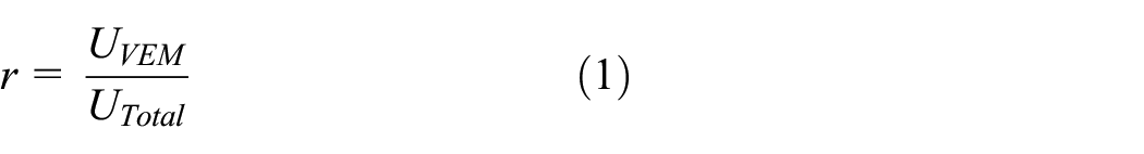
Figure 3 represents the relation between the non-dimensional thickness ratio h2 (ratio between the thickness of the VEM layer and the host beam length) and the normalized damping loss factor (η) determined by the application of the modal strain energy (MSE) concept.24–26 The MSE determines the modal loss factor of the structure from the ratio between the strain energy stored in the VEM layer multiplied by the material loss factor (here considered to be unitary for the sake of simplicity) and the total strain energy for the complete structure, including the host structure, the VEM layer, and the constraining layer, as described by Equation (1). In this case, the thickness of the constraining layer (H3) is equal to the thickness of the host beam (H1), and an ILD configuration can be assumed.
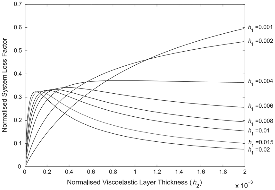
Efficiency curves for symmetric sandwich beam (ILD configuration with h3 = H3/H1 = 1). 23
The graph in Figure 3 clearly shows that while the evolution of the damping effect of the VEM layer for relatively thin beams (for h1 < 0.004 where h1 is the ratio between H1 and L) follows a direct and monotonic relation, for thick beams (for h1 > 0.004) this monotonic relation is not observed and in turn a peak in the curve is observed. This peak indicates an optimum value for the VEM layer thickness, depending on the geometric parameters and material properties of the host/constraining beams, and that applying thicker VEM layers may reduce the damping effect.
This behavior can be explained when looking at the evolution of the shear strain and the VEM volume with the increase in the VEM layer thickness (Figure 4). On one hand, the material amount contributing for the storage of deformation energy increases proportionally to the VEM layer thickness. On the other hand, the shear strain reduces with the VEM layer thickness. The combination of these two contributors for the strain energy stored inside the VEM layer justifies the behavior depicted in the graph of Figure 3.
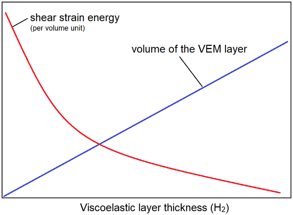
Variation of the two contributors in the stored strain energy for a beam with a constrained/integrated layer damping configuration. 27
These results evidence the issue related to the design of efficient damping treatments applied to beams (and plates) with high thickness/length ratios. Therefore, a novel strategy is proposed to solve this problem: the corrugated viscoelastic layer (CVL) damping treatments.
The concept of CVL damping treatments (Figure 5) proposed here is quite simple and is based on the use of external beams (host and constraining beams) whose internal surfaces are not flat but instead exhibit indentations. These indentations force the VEM layer to conform in a waved configuration during the sandwich assembly. This waved or corrugated configuration intends to promote the deformation of the VEM layer in the first bending modes of vibration.
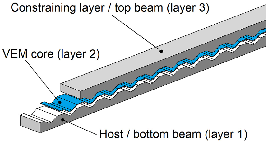
Corrugated VEM layer configuration.
2. Methodology
The analysis of the sandwich beams with VEM damping treatments, either using an ILD configuration or a CVL configuration, was performed using the finite element method. For that purpose, the NX. Natran solver, aided by the Siemens FEMAP pre- and post-processor software, was used. In addition, a tool in The Mathworks Inc. Matlab was created for automatic mesh generation based on the geometric parameters of the sandwich beam.
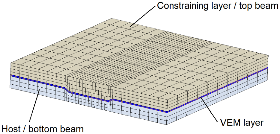
The sandwich beam is modeled following the three-brick layer approach 11 (Figure 6), where each one of the three layers is represented by an eight-noded hexahedral finite element to simplify the modeling task while reproducing accurately the shear strain pattern developed inside the viscoelastic layer.
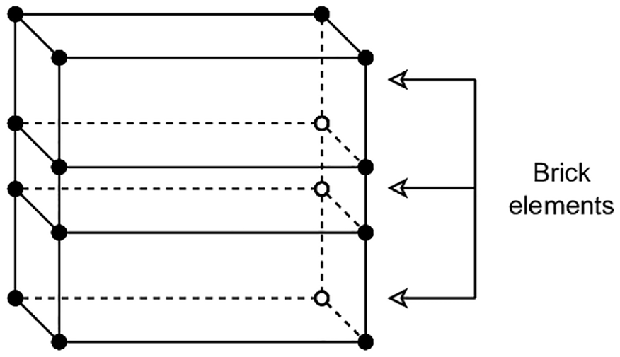
Three-brick layer model used to represent the sandwich beam.
This modeling approach is often applied with commercial finite element packages since the hexahedral finite elements are readily available. However, it requires a laborious and time-consuming mesh generation task, especially when dealing with complex three-dimensional shapes. It is also important to mention that the hexahedral elements that represent the VEM core typically have a high aspect ratio, requiring the use of special formulations to avoid shear-locking issues. In this case, the CHEXA8 finite element formulation from NX. Nastran was used. This formulation uses a reduced integration scheme coupled with non-conforming interpolation to reduce the shear-locking issues while avoiding the spurious deformation energy modes (hourglass modes).
The structure under analysis is a sandwich beam with length L and width w formed by a prescribed number of geometric cells of length 2 × Lm (Figure 7). Each cell represents a single indentation.
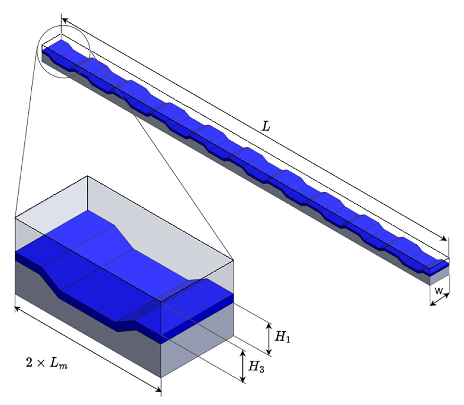
Modular scheme applied to the spatial model of the corrugated VEM layer configuration.
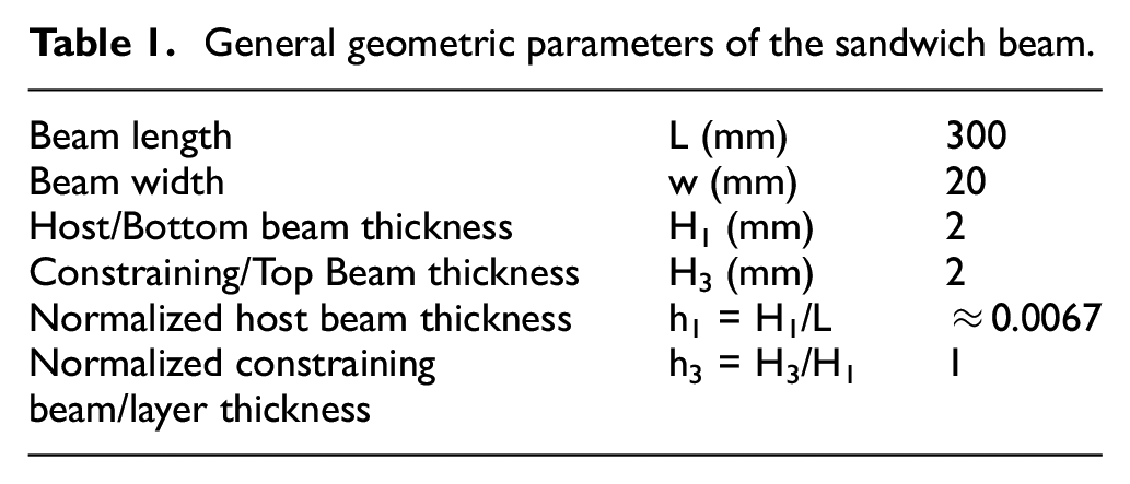
Table 1 presents the general geometric parameters used in this study. The thickness of the VEM layer (H2) is herein a design parameter and will vary during the analysis process.
General geometric parameters of the sandwich beam.
The corrugated geometry of the sandwich beam is parametrized, as represented in Figure 8. As illustrated in the figure, nine regions are defined where the first letter identifies the indentation region (A—surface of the original beam, B—indentation slanted wall, and C—indentation bed), and the numeral identifies the layer (1—bottom/host beam, 2—core/VEM layer, and 3—top/constraining layer).
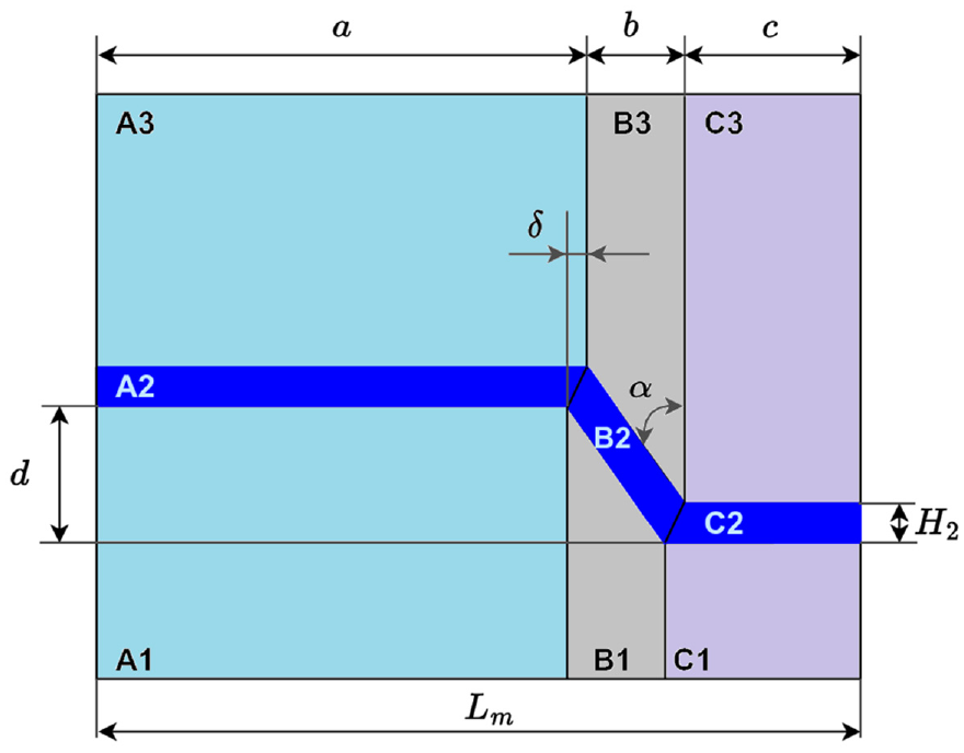
Parametric representation of the sandwich with corrugated VEM layer (half of a cell).
Table 2 lists the design parameters applied in this study and includes the thickness of the VEM layer (H2), the number of waves created along the entire beam length (N), the depth of the indentations (d), the angle between the indentation wall and the vertical line (α), and the width of the flat bottom of the indentation (c = c* × Lm).
Design parameters applied in the analysis of corrugated sandwich beams.
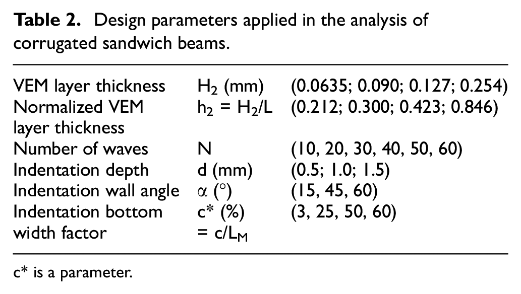
c* is a parameter.
The values defined in Table 2 were selected, aiming for a complete exploration on the possible range of these geometric parameters. The values for the thickness of the VEM layer were selected based on two premises: first, they represent the typical thicknesses of commercially available VEMs for damping treatments (2.5, 3.5, 5, and 10 mils), and second, these values correspond to points A, B, C, and D in the dotted curve of Figure 9. This curve represents the efficiency curve as defined by Sher and Moreira 23 and Sher 27 for the ILD beam configuration used in this study as a reference for assessing the corrugated VEM layer configuration. This curve is limited to the first bending mode of the sandwich beam. Points A (H2 = 0.0635 mm), B (H2 = 0.090 mm), C (H2 = 0.127 mm), and D (H2 = 0.254 mm) represent a configuration just before the efficiency optimum peak, close to the peak, immediately after the peak, and far from the peak in the descent portion of the curve, respectively.
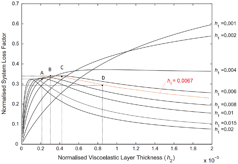
Efficiency curve for the reference ILD beam configuration (h1 = 0.0067).
To generate the solid finite element mesh (stacked hexahedral finite elements forming the complete sandwich beam), the authors developed an automatic generation process using a Matlab tool specifically for this purpose.
These Matlab routines start by generating the six domains of a half of a single cell (as represented in Figure 8) based on the geometric parameters described in Tables 1 and 2. Then, for each domain (from A1 to C3), it determines the coordinates of the nodes and elements connectivity matrix based on the desired mesh detail level (number of elements along each direction). As a result, a planar mesh is created representing half of a cell, composed by four-sided elements, after performing a check and replacement of coincident nodes (since those appear duplicated along the domain borders).
The second part of the tool applies an extrusion to the planar mesh, creating thus the three-dimensional geometry of half of a cell (represented by hexahedral elements with eight nodes) followed by a symmetry operation to obtain the mesh for a complete cell of the beam. This mesh is then multiplied considering the desired number of waves, thus creating the mesh for the complete beam.
In the end, the mesh information is written to a file following the Nastran bulk data format and imported to FEMAP where material properties and analysis case are defined and applied. These Matlab routines are available at https://github.com/ruimoreira2023/CVL_mesh_generator.
In this study, a convergent mesh for the first three natural modes was applied. The number of finite elements was defined according to Figures 8 and 10, considering the following refinement in the horizontal direction for each region: A—six elements, B—two elements, and C—six elements, and in the vertical direction for each layer: 1—three elements, 2—two elements, and 3—four elements. In the direction of the width, 10 elements were applied for all regions and layers.
Finite element mesh defined for one beam module.
To reduce the computational cost of the analysis, a limited number of numerical layers were used to represent the three material layers. Nevertheless, this spatial model can approximately represent the shear pattern inside the thin VEM layer. It is important to emphasize that this number of numerical layers shall be increased, especially when dealing with thicker VEM layers.
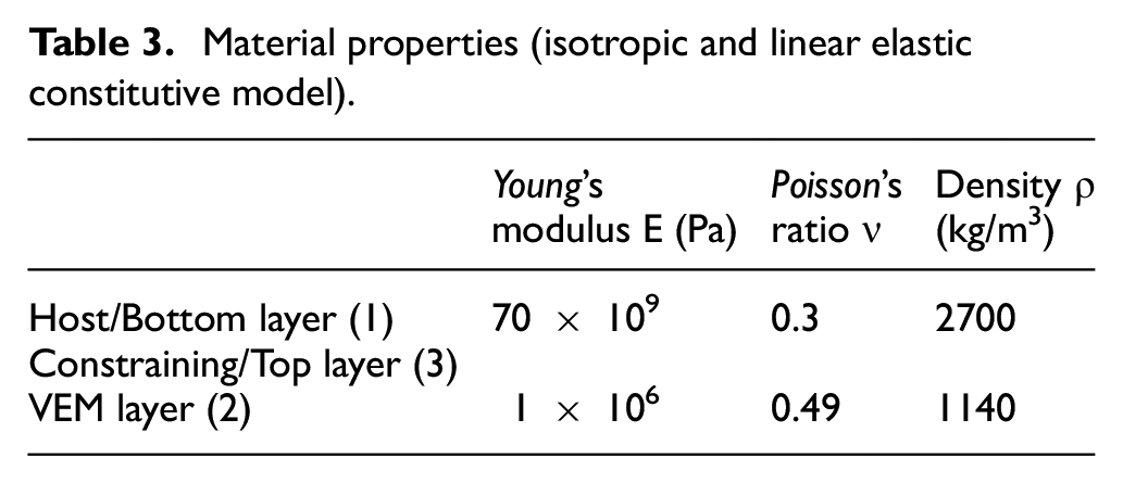
All the layers are represented by an isotropic linear elastic material with the properties listed in Table 3. The external beams of the sandwich are made from aluminum. The VEM properties correspond to the mean values of storage modulus, density, and Poisson’s ratio of a commercial damping material (3M ISD112) at room temperature (20°C) and a frequency range covering the natural frequencies considered in this study (100-700 Hz).
Material properties (isotropic and linear elastic constitutive model).
The study is divided into three main tasks:
Analysis of an ILD reference beam with the geometric and material properties listed in Tables 1 and 3, respectively. The thickness of the VEM layer varies between 0.0635 and 0.254, according to the selected points A to D identified in the graph of Figure 9.
Analysis of the corrugated viscoelastic layer configuration beam, following the geometric and material properties used for the ILD configuration and using the design parameters defined in Table 2.
Comparison analysis between the best reference ILD configuration (corresponding to point B) and the best corrugated viscoelastic layer configuration identified in the previous step.
The assessment of the sandwich beams (either those used as reference—the ILD configuration—or the new concept herein proposed—the corrugated viscoelastic layer (CVL) configuration) is made through the analysis of the natural frequencies and corresponding modal loss factor of the structure for the first set of real mode shapes of the sandwich beams (bending mode shapes).
It is important to remember here that even though the viscoelastic nature of the damping treatment leads to complex mode shapes (both when measuring those mode shapes experimentally and when using the complex modulus approach or any other viscoelastic constitutive representation in the frequency domain), the analysis described in this work does not account for the viscoelastic nature of the VEM and considers it as an isotropic linear elastic material. This simplicity does not affect the results of this analysis since the main observations raised here are directly related to the deformation energy storage process inside the VEM layer, so the linear elastic assumption can be applied.
Using the finite element method, the real natural modes of the sandwich beams are calculated, gathering information regarding the mode shape, the natural frequencies, and the MSE fields. In this study, free boundary conditions were considered.
Using the MSE approach,
24
the damping efficiency is calculated through the modal energy ratio (
where
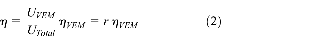
The MSE method considers that the damped structure can be represented by the mode shapes determined for the undamped structure. However, when a VEM layer is added to the sandwich beam, two aspects emerge that contradict this hypothesis. First, the soft core introduced between the external stiff beams may modify the shape of the natural modes or the order of the mode shapes. Second, due to the presence of the viscoelastic layer and in consequence the high damping level, the mode shapes become complex. Therefore, it is important to mention that, in this study, the MSE method is simply used to determine the strain energy ratio that relates the strain energy stored inside the VEM layer to the strain energy for the entire structure. Since the mode shapes are calculated for the sandwich beam with the VEM layer and the eigenvalue problem is solved in the real domain (as the VEM layer is considered elastic), none of the two limitations pointed above really apply. Yet, this approach can only be used for comparison between damping treatment configurations, and only more representative numerical modeling approaches, like the direct frequency analysis using a complex modulus approach, can provide representative results to be compared with experimental data.
3. Results and discussion
As described before, the initial part of the analysis is dedicated to the ILD configuration, where the VEM layer thickness represents the points A to D of Figure 9.
The bar graph of Figure 11 shows the modal loss factor (calculated from the strain energy ratio, as determined by Equation (1)).
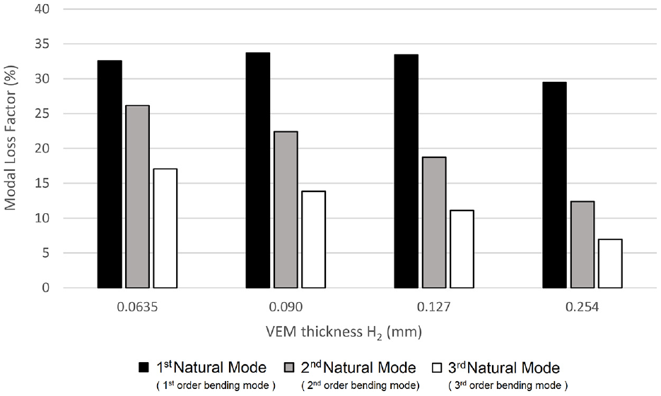
Efficiency values for the reference ILD beam configuration.
One can easily recognize the non-monotonic evolution of the values when the VEM layer thickness increases from 0.0635 to 0.254 mm. It is also evident that the energy ratio (that represents the damping treatment efficiency) for point B (H2 = 0.090 mm) is higher than those obtained for lower and higher values of the thickness of the VEM layer. These results agree with those obtained in the non-dimensional analysis performed by Sher and Moreira, 23 where a three-layer beam model was used.
For higher-order natural modes (for the second-order bending mode and the third-order bending mode), the efficiency varies monotonically but with an inverse relation to the VEM layer thickness. This result is expected since, according to the results gathered in the work by Sher and Moreira, 23 the efficiency curves for higher-order natural modes precisely follow the shape of the curves depicted in the graph of Figure 9 but with the peak regions appearing at lower values of the VEM layer thickness. Therefore, in this range of VEM layer thicknesses, the efficiency curves are already on the right side of the efficiency peaks.
It is well known that very thin VEM layers can provide higher loss factor values for higher-order modes than for lower-order modes. 23 Observing the graph in Figure 11, it is possible to conclude that, while the loss factor for the first natural mode has a peak for VEM layer thickness around 0.090 mm, the loss factor results for higher-order natural modes evidence a rising trend when the VEM layer thickness reduces. These results agree with those observations gathered by Sher and Moreira, 23 indicating that the loss factor peak for the higher-order modes occurs for VEM layer thickness values lower than 0.0635 mm.
When analyzing the natural frequencies represented in the graph of Figure 12, one general observation can be drawn—independently of the natural mode order, there is an inverse relation between the natural frequencies and the VEM layer thickness. This observation validates the decoupling effect discussed before, which reduces the beam bending stiffness since the additional mass due to the VEM layer thickening cannot entirely justify the decrease in the natural frequencies. This decoupling effect is due to the soft VEM core, which is regarded as a drawback of the ILD configuration.
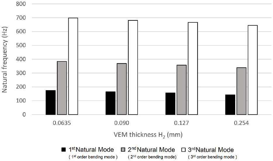
Variation of the natural frequencies for the reference ILD beam configuration.
Regarding the corrugated viscoelastic layer configuration, here denoted as CVL, the study explored the effect of all the design parameters described and quantified in Table 2. For the sake of brevity, only the optimal values within the design values domain are discussed here, but the reader can find the complete study in the work published by A.P. Marques. 28
In general, the exploratory study concluded that
The CVL treatment configuration outperforms the ILD configuration for VEM layer thicknesses higher than those that produce the efficiency peak (point B in Figure 9).
The number of indentations does not present a monotonic relation, but for the region at the right of the efficiency peak, an optimal value of waves can be defined according to the thickness ratio h2 and natural mode order, and depends on the effect of the other design parameters, especially the indentation wall angle (
There is a direct relation between the optimal number of waves and the order of the bending natural mode (higher-order modes require more waves since there is a clear relation between the required number of waves of the treatment and the number of waves of the bending mode shape).
The effect produced by the wall angle (
The width of the indentation bed (c) does not significantly affect the damping efficiency; in general, higher c values tend to reduce efficiency. This reduction is more apparent for deeper indentations (higher values of d).
The indentation depth (d) also presents a non-monotonic effect, and the results evidence that very deep indentations (indentation depth values higher than half of the host beam (d > 0.5 H1) reduce the damping efficiency, and in general, values between 10% and 35% of the host beam thickness produce the best results.
Based on the abovementioned exploratory study, a set of parameters corresponding to the best CVL configuration is here used to demonstrate the benefits of this proposed concept against the conventional ILD treatment configuration. This optimal set of parameters belongs to the design parameters domain defined in Table 2 and corresponds to
The graph of Figure 13 compares the efficiency results (
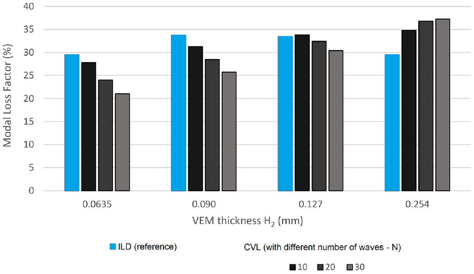
Comparison between the reference configuration (ILD) with the proposed CVL configuration with different number of waves (N)—first bending mode.
As mentioned before, it can be observed that the benefit of the CVL configuration is only met for VEM layer thicknesses higher than the value corresponding to the efficiency peak (H2 > 0.090 mm). In that region, the benefit of the corrugations is clearly observed, and it is also possible to see that the efficiency provided by a higher number of waves is evident when the VEM core becomes thicker. However, the exploratory work 28 also demonstrated that this relation is non-monotonical and that there is an optimal value for the number of waves as well, and that it depends on the other design parameters, especially the VEM core thickness. The graph of Figure 14 evidence this non-monotonic relation for the thickest VEM core considered in this study (H2 = 0.254 mm)
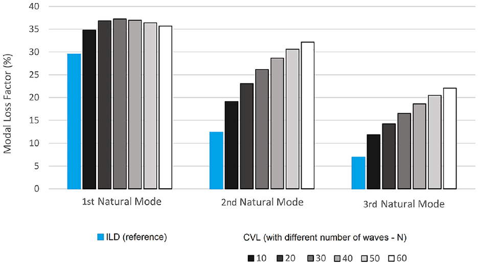
Comparison between the reference configuration (ILD) with the proposed CVL configuration with different numbers of waves (N) for the first-, second-, and third-order bending natural modes—H2 = 0.254 mm.
The graph of Figure 14, in addition, shows the effect of the order of the bending natural mode of the beam on the damping efficiency obtained for both configurations: ILD and CVL. Two observations can be drawn from these results.
First, as observed by Sher and Moreira, 23 higher-order natural modes tend to shift the peaks of the efficiency curves depicted in Figure 9 to the left. For that reason, it was expectable to get lower efficiency values for the ILD configuration with the same VEM layer thickness (H2 = 0.254 mm) for the second and third bending natural modes since, at the right of the peak, the efficiency curve presents a downward trend. This observation also agrees with the commonly accepted rule that higher-order bending modes can be efficiently damped using very thin damping layers.
The second observation from Figure 14 is associated with the relation between the natural mode order and the effect of an increasing number of waves. As evidenced, the efficiency of the CVL damping treatment increases with an increasing number of indentations for the second- and third-order bending modes. The relation between the efficiency and the number of indentations for higher-order bending modes is expected to continue to be non-monotonic. However, the peak of this relation shall occur for a higher number of waves.
The analysis of the wavelength of the mode shapes can support this last assumption. Comparing the first bending mode with the second bending mode for the free boundary conditions herein considered, one can quickly realize that the wavelength of the latter is approximately half of the wavelength of the first bending mode, hence justifying the need for more waves (theoretically the double) to produce the same effect.
Regarding the natural frequencies, Table 4 presents the natural frequencies for the ILD and CVL configurations for the first bending mode (
Comparison of natural frequencies for the first bending mode between ILD and CVL configurations.
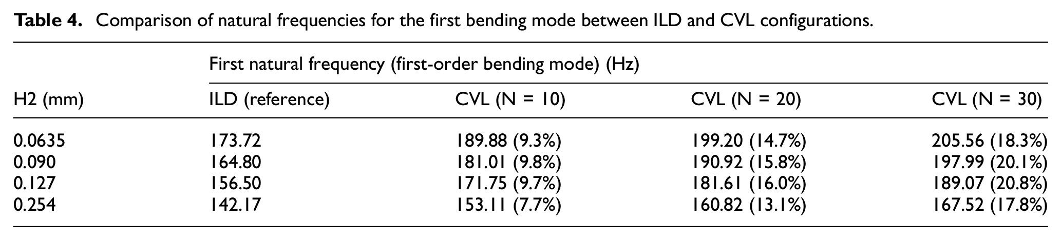
When a soft VEM layer is inserted in the core of a sandwich beam, obtaining the ILD configuration, its flexural stiffness reduces in proportion to the thickness of this layer. Due to this stiffness reduction, the natural frequency values for the bending and torsion modes reduce when compared to the pristine beam. 21 The results listed in Table 4 evidence higher natural frequency values for the CVL configuration, which demonstrate that the stiffness decoupling effect is attenuated using this treatment configuration, especially when using higher number of waves in the corrugated VEM layer. This analysis between the natural frequency and the stiffness of the sandwich beam is feasible because the mass value and distribution of all the configurations are kept constant.
The presence of indentations created in the inner surfaces of the skins of the sandwich beam with VEM core not only increases the damping efficiency, making possible the use of thicker VEM layers with improved damping efficiency results (as observed in Figure 13), but also reduces the decoupling effect due to the soft VEM core.
Figure 15 illustrates the MSE plot for the ILD and CVL configurations (H2 = 0.254 mm), evidencing the localized shear strain effect around each indentation. This plot corresponds to the top view of the beam and is limited to the MSE of the VEM layer (bottom and top beams were omitted). For the sake of simplicity, only the beam’s left half is presented due to the symmetry of the model and results.
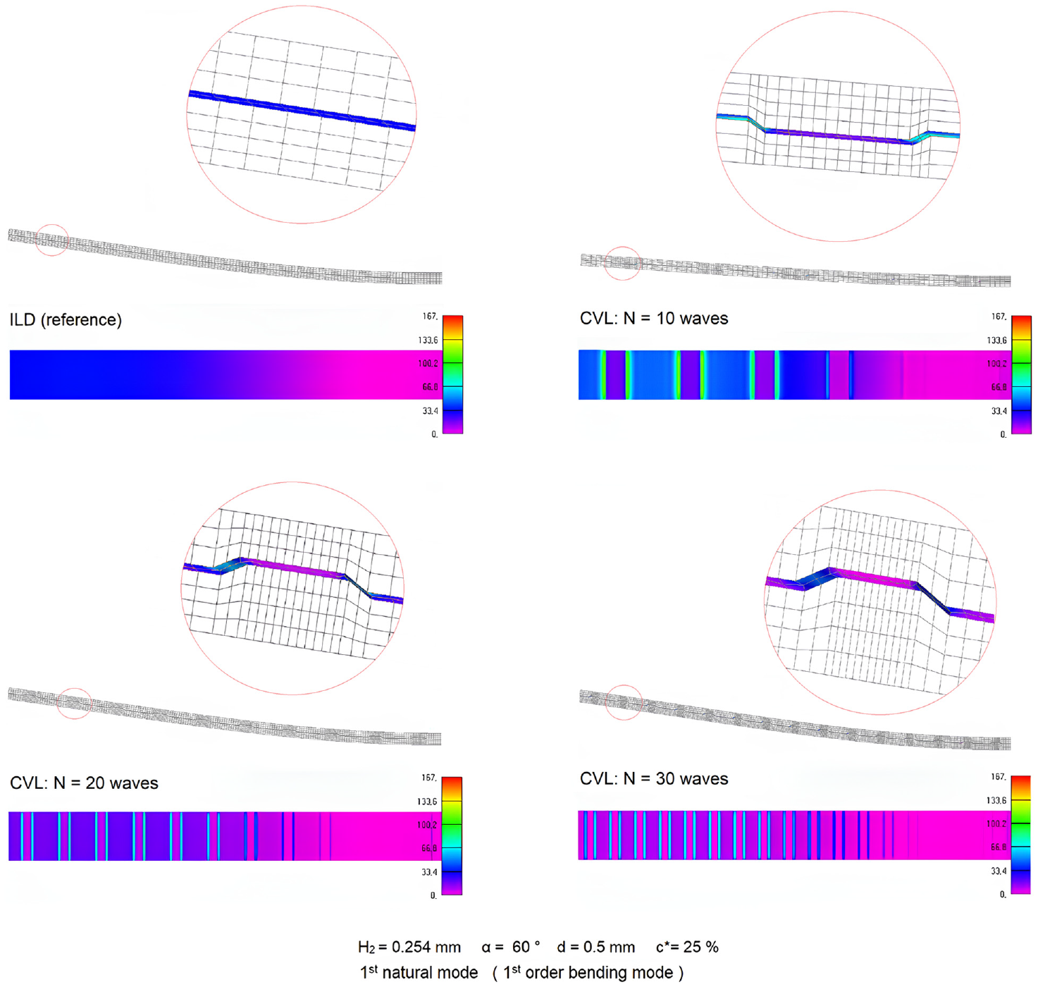
Modal strain energy distribution for the first natural mode (first-order bending mode) for H2 = 0.254 mm.
Figure 16 represents the effect of the design parameters in the natural frequency of the first natural mode (first-order bending mode). The fixed values for the variation of one specific parameter are always H2 = 0.254 mm, N = 30, d = 0.5 mm, c* = 25%, and α = 60°.
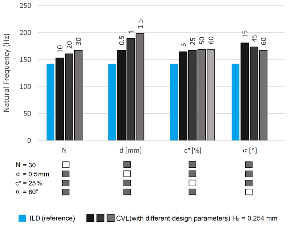
Effect of the CVL design parameters in the natural frequency of the first natural mode (first-order bending mode) for H2 = 0.254 mm.
From the results depicted in Figure 16, it is possible to observe that the natural frequency depends directly on the number of waves (N) of the corrugated configuration. The same relation is observed between the natural frequency and the depth of the corrugations (when the indentation depth d increases, the natural frequency also increases). The length ratio of the bed of the indentation (c*) has also a direct but meaningful effect on the natural frequencies, whereas the angle of the corrugation wall (α) has an inverse relation (higher values of α, meaning that the inclination of the corrugation wall is lower, produce a reduction on the natural frequencies). In general, it was observed that when the corrugations are more noticeable (deeper and abrupt transitions) it tends to increase the natural frequencies.
4. Conclusion
The VEM damping treatments provide an efficient solution to add the required damping capability to light structures that undergo vibration problems and premature failure due to imposed dynamic loads. These treatments are very effective and straightforward to apply. However, the design of such treatments is not simple, especially for the CLD and ILD configurations which requires special modeling techniques to account for the high shear pattern developed inside the VEM core. Moreover, the relatively low modulus of the VEM core in the ILD configuration is responsible for reducing the flexural stiffness of the sandwich structure due to the decoupling effect produced by the soft core.
In this work, a novel configuration is proposed and assessed. The proposed corrugated viscoelastic layer (CVL) configuration is produced by creating indentations in the inner face of the sandwich skins (host/bottom and constraining/top layer) that force the VEM layer to assume a waved shape along the beam length.
In the end, it was verified that the waved shape of the VEM contributes positively to the efficiency of the damping treatment. The CVL configuration allows the efficient use of VEM layers thicker than those identified as the optimal values for the ILD configuration, providing higher values of modal loss factor and a reduced decoupling effect due to the soft VEM core.
This study identified a set of optimal design parameters. Shallow indentations seem to produce the best results, and it was also observed a non-monotonic effect of the number of indentations. Higher-order bending modes require more indentations, and there is also an optimal number of indentations depending on the rest of the design parameters (but it mostly depends on the wavelength of the selected bending mode shape).
Footnotes
Funding
This article was supported by the projects UIDB/00481/2020 and UIDP/00481/2020 - Fundação para a Ciência e a Tecnologia (DOI 10.54499/UIDB/00481/2020 and DOI 10.54499/UIDP/00481/2020).