
Abstract
This paper presents an experimental study of the vibration attenuation achieved by the combined action of Constrained Layer Damping (CLD) and piezoelectric patches. The test structure is a cantilever beam excited at the clamped end, and the objective is to reduce the vibration of the free end. It will be shown that the most effective combination is to clad 25% of the length of the beam with CLD on just one side, and adhere a piezoelectric patch on the constraining layer rather than on the beam itself. It will also be shown that adding CLD and patches on both sides does not further improve attenuation. To guide the experimental analysis, and predict beam behaviour prior to testing, a model has been developed to include CLD cladding and piezoelectric patches. The model is based on the simplified Euler–Bernoulli beam but taking into account the stepped or segmented nature of the beams under consideration. Mode shapes are obtained for each segment and assembled imposing continuity. Experimental results show that the model can be used as a valid first approximation.
Keywords
Introduction
Structural vibrations are very often undesirable in a wide range of industries and applications. Metallic structures usually lack sufficient damping to cancel or mitigate vibrations. According to Johnson, 1 around 85% of passive damping systems used viscoelastic materials. They are still widely used today in sectors such as the automotive,2,3 railway 4 and aerospace5,6 industries, but they are mostly focused on noise reduction rather than on reducing the vibrations transmitted to passengers. Viscoelasticity is exhibited by materials with long molecular chains suitable for converting mechanical deformation into heat. The phenomenon is very sensitive to temperature and frequency. Viscoelastic materials show a glassy region, usually at high frequencies and/or low temperatures, where the mobility of the polymer chains is hindered; an elastic region, at low frequencies and/or high temperatures, with less restricted chain mobility that allows high and reversible deformations; and an intermediate transition region suitable for energy dissipation.
The most widespread viscoelastic technique is Constrained Layer Damping (CLD). It consists of applying a viscoelastic layer sandwiched between a rigid constricting layer and the structure itself in order to create shear strain in the layer rather than axial deformation. 7 Under these conditions the viscoelastic layer is able to dissipate more energy in the form of heat than in configurations without a constricting layer.8–10
In addition to viscoelastic damping, piezoelectric materials are another widely adopted solution to increase structural damping by offering high, fast, linear and robust electro–mechanical coupling. Direct piezoelectricity is the generation of electrical charges when a mechanical stress is applied. The stresses on the material cause the rotation of the electric dipoles, creating an apparent charge flow between the electrodes and thus an electric displacement. Many works can be found in the literature where inverse piezoelectricity is used in active control systems.11–15 Conversely, the direct piezoelectric effect can be used to harvest16,17 or to passively dissipate the electrical energy generated by deformation by connecting the patch to shunt circuits. 18
The most robust, stable and energy–efficient dissipative shunt circuits are purely resistive (R–shunt).19–23 The dynamic behaviour of these shunt circuits is similar to that of viscoelastic materials: it adds a frequency–dependent loss factor to the structural dynamics but, unlike viscoelastic materials, the loss factor fortunately remains relatively insensitive to temperature variations. Alternatively, resonant shunt circuits (RL–shunt)20,21,23–25 are the electrical analog of a dynamic vibration absorber tuned to the natural frequency of the host structure. 18 However, RL circuits designed to operate in the low frequency range (as is common in railway structures), require high inductances which can only be achieved via synthetic electronic circuits such as the one proposed by Antoniou 26 or more recently by Dekemele for high–voltage synthetic inductors. 27 This technique turns piezoelectric systems with RL shunt circuits into semi–passive systems because of the need to power the operational amplifiers. 18 Vibration cancellation of flexible structures with RL shunt circuits has been studied by several authors: dell’Isola et al. 28 applied it to a cantilever beam; Hassan et al. 29 tried series and parallel RL shunt circuits; and later Lossouarn et al. 30 proposed new synthetic inductance designs. Recent studies have proposed advanced shunt circuits, such as optimal elementary shunt circuits to replace multi–branch shunt circuits, 31 LRLC–shunt circuits, 32 self–tuning RL–shunt circuits, 33 or multi–frequency adaptive tuned mass dampers based on shunt circuits with negative capacitances. 34
Despite the rich literature using and comparing 35 CLDs and piezoelectrics with shunt circuits, hybrid systems passively combining both techniques have received less attention. A few studies can be found where the CLD is optimised to cancel vibrations in the high–frequency range and the piezoelectric shunt circuit is designed to target vibrations in the low–frequency range. For example, the works of Chul et al., 36 those from Larbi’s research group,37–42 and more recently that of Araújo and Aguilar. 43 The integration of both techniques by constraining the viscoelastic layer with the piezoelectric material itself was proposed by Ghoneim 44 under the name “Electromechanical Surface Damping” (EMSD). It was used, again, to extend the range of actuation, optimising the viscoelastic for the first mode of vibration and the shunt circuit for the second. Ghoneim later extended the studies to a plate–type structure by applying two EMSD elements.45,46
The work presented here is an experimental study that, starting from the separate optimisation of both, the CLD and the piezoelectric patches, combines them to study hybrid systems. To the best of our knowledge, hybrid techniques have only been studied to extend the frequency range, but have not been combined to maximise damping of a single mode of interest. On the other hand, a model is presented to study any combination of layers including piezoelectric materials. In contrast to similar models found in the literature, mode shapes have been tailored to the stepped or segmented nature of the beams under consideration.
Model
The notation in this section tries to avoid conflicts between usual electrical symbols and standard mechanical notation. Thus, for example,
Modal parameters for a beam of variable section
The equation of motion for a uniform Euler–Bernoulli beam in free transverse vibration is

where
By testing harmonic solutions with separated variables,

where
The mode shapes for a uniform beam are of the type
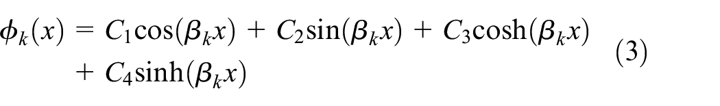
where constants

Beam segments and layers.
Consider the beam in Figure 1 with
Let the origin of coordinate

where

from the origin.
The equivalent parameters of each segment can now be calculated as
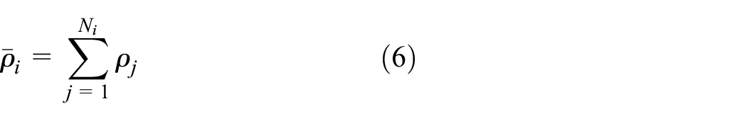
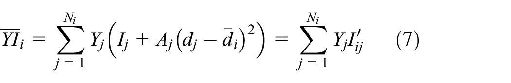

where
As mentioned, equivalent parameters are used in equation (3) to obtain the following expressions:

where
Four boundary conditions must be imposed at each segment transition, as well as two at each end of the beam. A system of

and normalised so that the integral along the beam of the mode shape squared is one.
Piezoelectric layers
Some of the layers in the model above are piezoelectric layers in which mechanical and electrical responses are intertwined. Strain is not only caused by mechanical stress but by electric fields as well. Likewise, electric displacement is not only due to electric field, but to mechanical stress as well. Let us assume that stress is unidirectional (

where
Equation (11) may be inverted to obtain

where
The potential energy per unit volume, stored as mechanical strain and electric displacement, is

Since

In an Euler–Bernoulli beam, the strain at a distance

The assumption will now be made that the shape functions obtained in Section “Modal parameters for a beam of variable section” hold in the case of some layers being piezoelectric. Moreover, it will be assumed that the first mode suffices to account for beam vibration, in which case

where

On the other hand, the electric displacement (

where

where
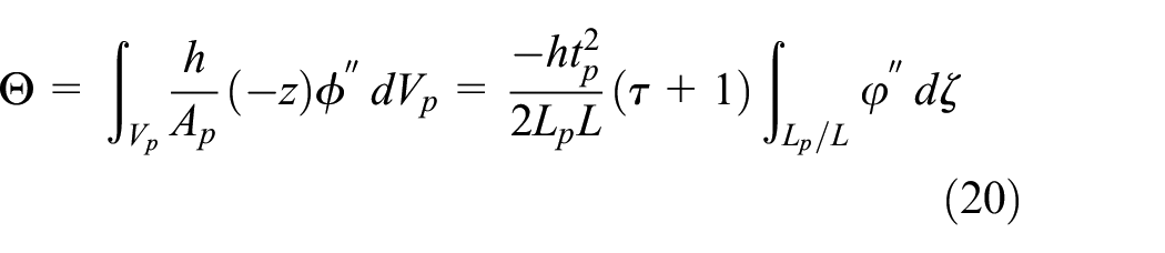
where
Dynamic equations
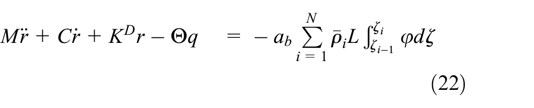
Let us now consider the dynamics of a segmented cantilever beam, with possible piezoelectric layers and CLDs, subjected to the motion of its clamped end with acceleration

where

where

The damping coefficient
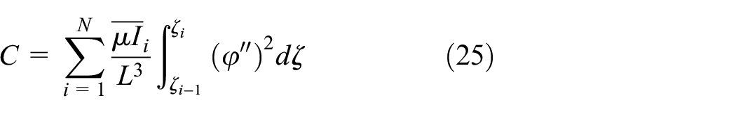
Likewise,

and

Voltage in equation (23) may be supplied by a voltage source or may be related to current (rate of change of electric charge) via an external shunt circuit. In the case of a resistor–inductor (RL) shunt circuit, the relation is

where
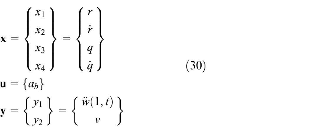
It is often convenient to rewrite these equations in a state–space form in which
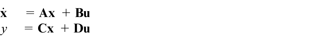
where vector
For the RL shunt circuit, the system state comprises modal coordinate
It can readily be seen that, with these definitions and equation (28), the system matrices are
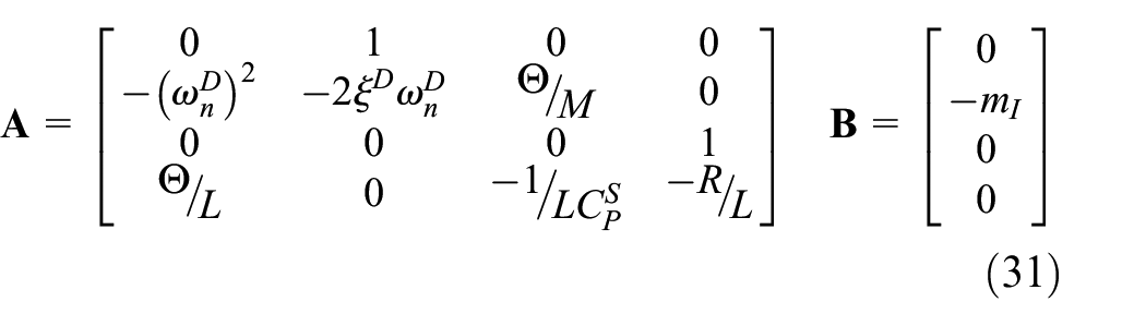
and

where

These state–space equations may be simplified for specific cases such as short circuit, open circuit or resistive shunt circuit (without inductance). The simplified systems are shown next.
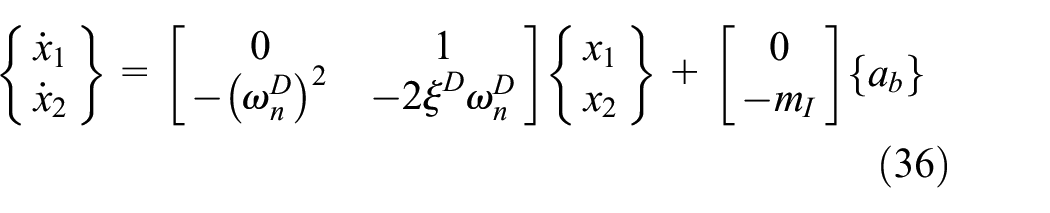
Short circuit
When the electrodes of the piezoelectric layer are short–circuited (

and

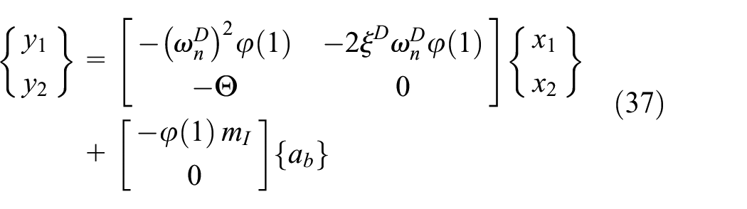
Open circuit
When the piezoelectric patch is left open circuit (
and
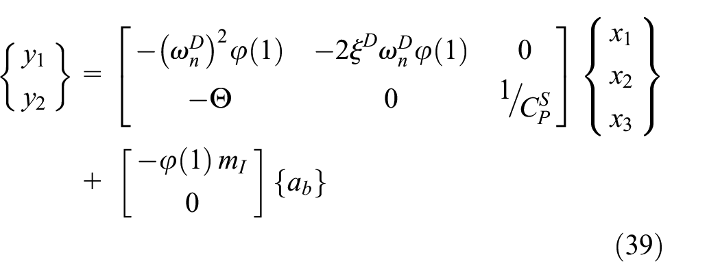
Resistive R–shunt circuit
If the piezoelectric patch is shunted with an ideal resistive R–circuit, charge must be retained as a state–space variable, but its second derivative is null. In this case

and
Methodology
Specimens
A laboratory–scale (292 mm long, 35 mm wide and 3 mm thick) cantilever aluminium beam is the “host” structure to test several configurations of constrained layer damping (CLD) attachments and piezoelectric layers. The goal is to reduce the vibration response when the clamped end is shaken at different frequencies.
The CLD patches in our study are composed of an aluminium sheet that acts as a constricting layer, and a very thin film of viscoelastic material. The viscoelastic material is commercially manufactured by Heathcote Industrial Plastics (HIP). Its mechanical properties (shear modulus and loss factor) depend, not only on temperature, but on excitation frequency as well. Constant temperature conditions are considered in this study. Two types of CLD have been studied: a 0.13 mm thick viscoelastic polymer layer constrained by a 0.5 mm thick aluminium sheet (labelled 2005); and the same viscoelastic layer constrained by a 1.0 mm thick aluminium sheet (labelled 4005).
The piezoelectric patches in our study have a nominal maximum operating voltage between 100 and 1000 V, depending on the active layer thickness. The patches are laminated structures consisting of a piezoceramic plate, electrodes and polymer materials, manufactured with bubble–free injection methods. The polymer coating simultaneously serves as electrical insulation and mechanical preload (to allow bending). Three types of piezoelectric patches manufactured by PI Ceramics have been selected, namely models P–876.A11, P–876.A12 and P–876.A15 (just A11, A12 and A15 hereafter). Their main properties are summarised in Table 1. In all three patches the piezoelectric material is PI Ceramics’ PIC255, which is a modified lead zirconate titanate.
Piezoelectric patch characteristics.

As mentioned, several configurations of constrained layer damping attachments and piezoelectric layers have been studied. Figure 2 shows all configurations.

Specimen types and labelling convention.
Specimens with piezoelectric patches are referred to by the patch type (P = A11, P = A12 or P = A15), a subscript which specifies the number of patches (
Hybrid cases with CLD as well as piezoelectric patches have also been studied. Hybrid specimens are labelled by juxtaposing the CLD and patch descriptions. In this case, however, the second patch subscript is allowed to take two new values to indicate whether the single patch is adhered to the beam (
Test bench
Figure 3(a) shows a schematics of the excitation and measurement systems. The excitation system is an electrodynamic shaker model V5344 from Data Physics, connected to a slip table. Figure 3(b) shows the test bench and a ready to test specimen with its connectors and sensors.

(a) Schematics of the excitation and measurement system and (b) actual test bench.
The clamped end of the beam is firmly screwed to the slip table, and it is at this clamp where the control accelerometer is placed (see Figure 3(b)). This sensor is a Kistler model 8772A50 with a 50 g measuring range and 100 mV/g sensitivity. The response at the free end of the aluminium beam is measured by means of a miniature accelerometer from PCB Piezotronics model 352C22, with a 0.5 g mass, 500 g measuring range and 10 mV/g sensitivity.
These acceleration signals are recorded by means of a National Instruments data acquisition equipment (cDAQ–9174) and its NI–9234 sound and vibration input acquisition modules of 51.2 kS/s. Acceleration signals are post–processed to obtain frequency response functions between tip and excitation accelerations.
Numerical procedure
The state-space differential equations developed in Section “Model” have been solved in Matlab via the
Frequency analysis was also performed in Matlab via the
Results and discussion
CLDs
Figure 4 shows the FRF of beams with a single 2005 CLD (0.5 mm thin constricting layer) and different lengths. Following the nomenclature described above, these are specimens

Influence of cladding percentage for 2005 CLDs (
Figure 5 replicates the experimental results from Figure 4 by means of simulations using the model developed in Section “Model.” It can be seen that, even with the many assumptions adopted, a fairly accurate natural frequency evolution with CLD length is obtained. Note that the frequency axis is fairly narrow and that the errors are lower than 4%. Modal damping is also accurately predicted, but only after adjusting material damping parameters with experimental data. Comparison of Figures 5 and 4 allow us to consider the model validated and ready to be used in any beam–CLD combination.

Influence of cladding percentage for 2005 CLDs (
Figure 6 compares the FRFs for specimens with 25% CLD cladding and different constraining layers (types 2005 and 4005) as well as single or double–sided cladding configurations. The addition of viscoelastic material via two–sided cladding translates in significant reductions of the FRF peak because it is applied exclusively in the region of large strain. In addition, it is always better to use a constricting layer with higher inertia to maximise shear strain and thus energy dissipation. The experimental optimum among all possible CLD configurations was obtained for the

Influence of CLD type and configuration.
Piezoelectric patches
Figure 7 shows the FRF of the beam with a single A15 piezoelectric patch (

Influence of R–shunt circuit resistance for
Figure 8 shows the influence of RL–shunt circuit parameters for the same specimen (

Influence of RL–shunt circuit resistance and inductance for
Figure 9 shows the simulated results (using the model in Section “Model”) for the open and short circuit cases, as well as for a particular RL–shunt circuit. Modal frequency and modal damping for the short and open circuit cases are similar to those presented in Figure 7 (differences lower than 1%). A generalised electromechanical coupling coefficient

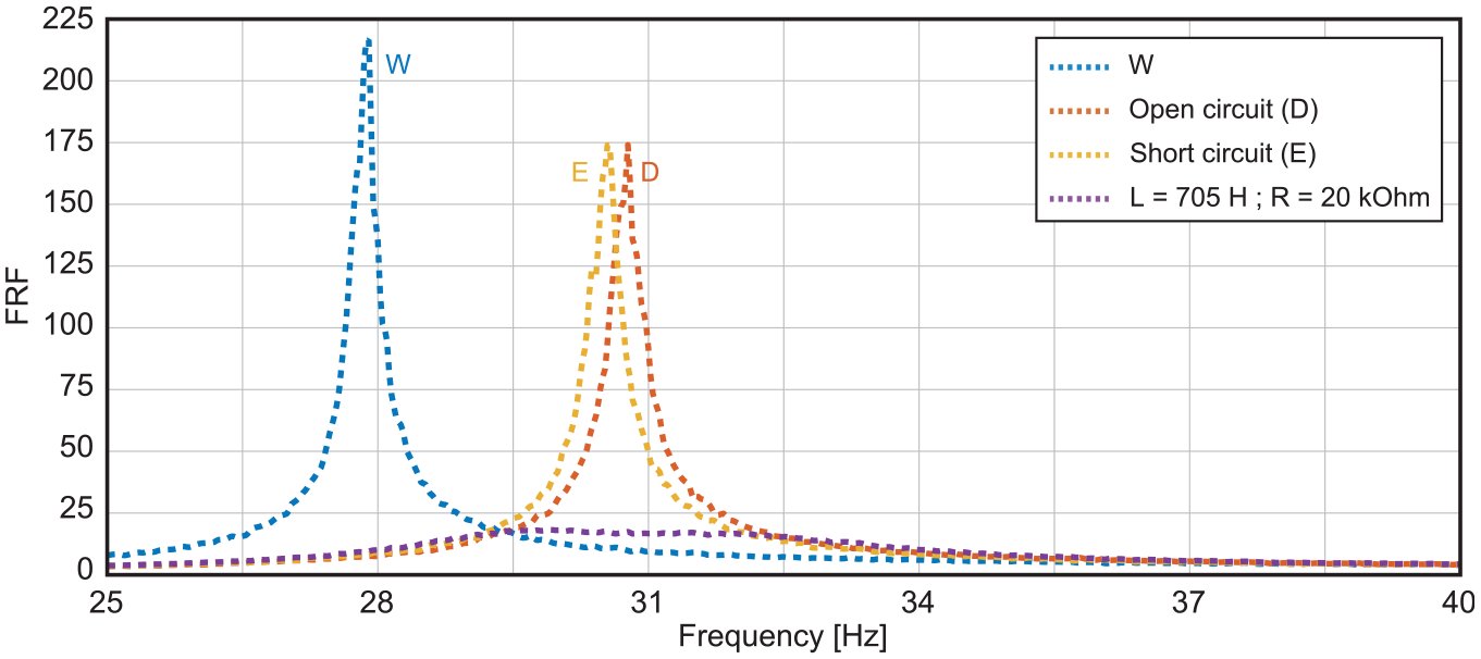
Model predictions in open, short and RL–shunt circuit for
Figure 10 compares three different piezoelectric patches connected to an optimised RL–shunt. The highest attenuation (

Influence of the type of piezoelectric patch.
Figure 11 compares the use of one or several piezoelectric patches (A15 with optimal RL–shunt) and their relative position in the case of bonding more than one. Differences among the three cases considered are subtle. The use of two patches is slightly better than the use of just one. And, indeed, when the two are on opposite faces of the beam also leads to slightly better peak reductions than when they are aligned on the same side. This is explained by the dependence of electromechanical coupling on modal deflection (see equation (27)), which is higher the closer to the clamp. Nevertheless, if forced to choose between very similar outputs, the choice would be the

Influence of the configuration of piezoelectric patches.
Hybrid systems
Figure 12 compares different combinations of CLD cladding and piezoelectric patches. The particular CLD and patch where found optimal when used independently: 25% of length clad in 4005–CLD, and A15 patch connected to a shunt circuit. It can be seen in the figure that combination

Influence of the hybrid configuration.
Figure 13 shows the attenuation predicted by the model for the shunted optimal case (

Model predictions in open, short and RL–shunt circuit for hybrid
Table 2 shows FRF peak values and attenuation with respect to the reference beam. The optimal configuration is
Summary of results.


Experimental (a) and simulated (b) results for the best hybrid (
Conclusions
The main conclusion is that there exists an optimum combination of CLD and piezoelectric patch that nearly cancels the vibration at the tip of the cantilever beam. The combination is the one labelled
It may also be concluded that one can get close to the attenuation level achieved by the hybrid optimum using just CLD cladding or just piezoelectric patches. However, both non–hybrid approaches have some drawbacks that need to be considered when choosing the damping technique. Attenuation with just CLD cladding significantly increases the resonant frequency, and using just piezoelectric patches may penalise energy consumption to synthesise the shunt circuit inductance.
The model developed here, using piecewise modal shapes, represents a fairly good first approximation to experimental results and can be used to predict the behaviour of any CLD–piezoelectric patch combination prior to testing.
Footnotes
Acknowledgements
The authors would like to show their gratitude to the manufacturer Heathcote Industrial Plastics for providing the viscoelastic CLD coatings.
Handling Editor: Sharmili Pandian
ORCID iDs
Funding
The author(s) disclosed receipt of the following financial support for the research, authorship, and/or publication of this article: This work was supported by grant PID2020–113747RB–I00, funded by MCIU/AEI/10.13039/501100011033 and “ERDF A way of making Europe,” and grant SBPLY/23/180225/000172, funded by JCCM–ERDF.
Declaration of conflicting interests
The author(s) declared no potential conflicts of interest with respect to the research, authorship, and/or publication of this article.