
Abstract
To enable real-time prediction of tunnel deformation induced by foundation pit excavation, this study develops a predictive framework that integrates an analytical solution based on a two-stage unloading method with a back-propagation neural network for parameter identification. The analytical model accounts for excavation-induced stress redistribution using Mindlin's solution, while the tunnel is modeled as a beam resting on a double-sided elastic foundation to represent its deformation behavior. Five key mechanical parameters are considered for inversion, including the initial residual stress coefficient, unloading reduction coefficient, longitudinal stiffness reduction factor, and the vertical and horizontal subgrade reaction moduli. These parameters are calibrated using field monitoring data through a trained back-propagation neural network. The proposed framework is embedded into a real-time prediction system and applied to the Gubei Road Station of Shanghai Metro Line 15, which is located adjacent to Line 10. The predicted tunnel displacements exhibit strong agreement with field measurements, with maximum relative errors of 21.82% in the vertical direction and 1.95% in the horizontal direction. Except during phases of displacement trend reversal, the system consistently maintains high predictive accuracy. These results verify the reliability of the proposed method for forecasting excavation-induced tunnel deformation and underscore its applicability in proactive risk management for urban tunneling projects.
Introduction
With the increasing number of metro lines put into operation in recent years, a variety of longitudinal structural issues—such as cracking, tensile failure, and uneven tunnel settlement—have become progressively more significant.1–5 Therefore, it is essential to predict and evaluate the longitudinal displacements of existing tunnels induced by unloading effects from adjacent foundation pit excavations. Accurate predictions facilitate timely mitigation of longitudinal deformation in shield tunnels, thereby ensuring the safe and continuous operation of metro systems.
The impact of foundation pit excavation on tunnel deformation has received extensive attention in recent years. Current investigations can be broadly classified into five categories: engineering case studies, numerical simulation, machine learning-based deformation prediction, real-time monitoring and control strategies, and analytical methods rooted in theoretical modeling.
Engineering case studies analyze tunnel deformation caused by excavation through laboratory experiments, field monitoring, and numerical simulations, typically relying on actual engineering projects or controlled experimental setups to collect deformation data and develop mitigation strategies. For example, Wei et al. investigated the influence of isolation piles on tunnel deformation and demonstrated that a well-designed pile arrangement significantly reduces deformation risks. 6 Bian et al. evaluated the protective effect of staged excavation on tunnels in soft soil environments. 7 Similarly, Wei et al. analyzed lateral loading and deformation behavior in shield tunnels caused by excavation and proposed mitigation measures based on full-scale testing. 8
Numerical simulation continues to serve as a primary approach for analyzing tunnel deformation induced by foundation pit excavation.9–15 Researchers establish numerical models to simulate excavation under various working conditions and assess deformation patterns in relation to changes in the surrounding soil stress field.16–19 Findings indicate that both longitudinal and transverse deformations can negatively impact tunnel structures, particularly in soft soil environments where deformation responses are more pronounced.
With the advancement of artificial intelligence, machine learning and other data-driven techniques have been increasingly applied to tunnel deformation prediction tasks. 20 These methods typically rely on historical monitoring data to train predictive models capable of producing rapid and accurate deformation forecasts. For instance, Feng et al. proposed an improved artificial bee colony-random forest model to predict tunnel deformation induced by adjacent excavation, demonstrating the capability of machine learning in capturing complex soil–structure interactions. 21 Wu et al. developed a hybrid model combining numerical simulation and machine learning for real-time deformation prediction during excavation. 22 Zhang et al. applied clustering analysis to monitoring data and established a time-series-based model for tunnel settlement prediction, offering a novel perspective on real-time forecasting. 23
Studies on real-time monitoring and deformation control typically utilize field data to develop feedback mechanisms, control measures, and engineering protection strategies.24–26 These efforts provide essential technical support for managing tunnel deformation during excavation and inform the formulation of targeted mitigation approaches. For example, Wei et al. investigated deformation patterns associated with different support structures in shield tunnels and proposed protective measures based on full-scale experimental results. 27 Han et al. integrated field monitoring and numerical simulation to analyze tunnel responses during excavation and formulated effective monitoring and prevention strategies. 28 Zhang et al. developed a reverse consolidation model for foundation pit bottom soils under continuous drainage conditions, incorporating real-time monitoring and stress-feedback mechanisms to enhance tunnel safety. 29
In addition to numerical simulation and experimental methods, analytical methods based on theoretical modeling provide simplified and efficient solutions for predicting tunnel deformation under complex conditions. These models are designed to enable rapid evaluation of deformation using closed-form mathematical formulations. For instance, Qiu et al. developed an analytical solution for evaluating excavation-induced tunnel deformation. 30 Zhuang et al. conducted numerical simulations to analyze tunnel behavior and proposed a simplified calculation approach. 31 Feng et al. enhanced the computational efficiency of conventional numerical techniques and introduced a concise analytical method for assessing tunnel deformation near excavations. 32 In a subsequent study, Feng et al. further integrated theoretical models with real-time monitoring data to improve prediction accuracy.33,34
A comprehensive review of existing studies reveals that most research on the impact of foundation pit excavation on tunnels relies on finite-element methods (FEMs) and theoretical analytical approaches. While FEM is a widely used and effective method, it requires significant technical expertise from engineers, as the selection of appropriate soil constitutive models and accurate determination of input parameters significantly influence the results.35–38 Additionally, existing machine learning models often rely heavily on historical data, which may inadequately capture site-specific variability and thus limit their generalizability to new or complex conditions. Analytical methods, by comparison, offer a more tractable mechanical framework that avoids the complexity of full three-dimensional modeling, allowing for faster and more straightforward evaluations. These methods are often employed to estimate the longitudinal deformation of tunnels caused by excavation. Currently, two principal theoretical approaches are employed: the residual stress method and the additional load method.30,33,34 The residual stress method is based on a layered summation technique, making it simple to apply; however, it overlooks the interaction between the tunnel and surrounding soil as well as the stiffness of the tunnel lining. Consequently, it cannot accurately capture the deformation behavior under excavation-induced unloading. The additional load method, also known as the two-stage analysis method, involves two sequential steps. In the first, the additional stress generated by excavation unloading at the tunnel location is computed using Mindlin's elastic solution. In the second, the tunnel is idealized as an infinitely long elastic beam on an elastic foundation, and a governing equation for longitudinal deformation is formulated and solved. However, this method introduces numerous parameters that are difficult to calibrate precisely, often resulting in discrepancies between analytical predictions and field measurements, which limits its practical applicability in engineering contexts.39–43
In practical engineering applications, on-site monitoring of tunnel displacements is routinely employed to evaluate the impact of excavation activities. Remedial measures are implemented when monitoring values exceed warning thresholds. However, beyond real-time observation, there is an increasing need for predictive methodologies capable of forecasting excavation-induced deformations in advance, thereby enabling proactive risk management and ensuring the safe and continuous advancement of tunneling operations.
For foundation pit excavations located above or adjacent to tunnels, a two-stage analytical method was adopted to estimate excavation-induced tunnel deformation. A back-propagation (BP) neural network,44–48 calibrated with field monitoring data, was employed to invert key model parameters. Building on this foundation, a real-time prediction system was developed to assess tunnel responses during excavation. This study presents an integrated framework that combines machine learning, real-time monitoring, and analytical modeling, enabling more accurate and responsive deformation predictions. The system significantly improves the capacity for proactive deformation risk management, thereby enhancing safety and stability in metro tunnel construction. Its effectiveness has been validated through successful application in practical engineering projects.
Derivation of analytical solution
For foundation pit projects adjacent to existing subway tunnels, the excavation process induces uplift of the pit bottom and inward horizontal displacement of the sidewalls. These deformations affect the surrounding soil and, when the tunnel is located within the affected zone, trigger soil–structure interactions between the displaced ground and the tunnel lining. Consequently, additional stresses are imposed on the tunnel structure, leading to tunnel deformation. The analysis of this process is typically conducted in two stages: first, the excavation-induced additional loads acting on the tunnel are computed; second, the resulting tunnel deformation under these loads is evaluated using an appropriate structural model.
Mindlin solution
In geotechnical engineering, additional stresses are typically calculated using elasticity theory. While this theory does not fully capture the complex behavior of soils under all conditions, it generally reflects their mechanical properties with sufficient accuracy for practical engineering applications. For three-dimensional additional stress calculations in engineering, the Boussinesq stress solution 49 and the Mindlin stress solution 50 are commonly used. The Boussinesq solution is suitable for estimating stresses in subsurface strata due to surface loading, whereas the Mindlin solution is used for evaluating stresses induced by subsurface or buried loads. Given the three-dimensional spatial interaction between foundation pits and adjacent tunnels, as well as the subsurface nature of the excavation activities considered in this study, the Mindlin solution is more appropriate for assessing the stress effects of lateral and overhead excavations on existing subway tunnels.
Although the Mindlin solution assumes a semi-infinite elastic medium, which does not fully account for boundary constraints such as diaphragm walls, it remains suitable for preliminary analytical modeling due to its simplicity and ability to capture the primary characteristics of stress propagation. In this study, subsequent parameter calibration using field monitoring data helps compensate for boundary effects by aligning the analytical predictions with observed tunnel responses.
As shown in Figure 1, according to the Mindlin solution,
50
when a vertical concentrated force Fv and a horizontal concentrated force Fh are applied at a depth c below the ground surface in a three-dimensional elastic medium, they induce horizontal additional stresses at a given point N(x, y, z) within the soil mass. The corresponding stress components in the two horizontal directions are given by


Stress analysis at a point induced by concentrated forces.
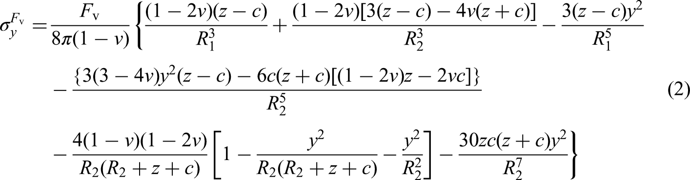
The vertical additional stresses are expressed as


Solution calculation of excavation unloading
Unloading at the pit bottom
When excavation reaches the bottom of the foundation pit, the resulting unloading effect can be represented by an equivalent upward rectangular uniformly distributed load, corresponding to the self-weight of the removed soil. However, due to the presence of residual stresses in the surrounding soil and the shielding effect of the pit's retaining structures, this load is not fully transmitted to the adjacent tunnel. Accordingly, adjustments to the equivalent load are required to more accurately reflect the actual stress redistribution.
Based on extensive monitoring data from foundation pit engineering projects,
51
the residual stress coefficient α has been found to correlate strongly with the excavation depth d and the thickness of the overlying soil layer. For a given excavation depth d, let h0 denote the distance from the calculation point to the pit bottom, i.e. the thickness of the overlying soil layer. The value of α increases progressively with h0, and when h0 reaches a certain threshold hr, α approaches unity and stabilizes. This suggests that below the depth hr, the unloading effect becomes negligible and the soil remains in its initial stress state. The depth h0, where α = 0.95, is commonly referred to as the residual stress influence depth, denoted hr. Based on a large volume of field data, Guo and Liu
51
proposed the following empirical relationship between α and hr:


Calculation of sidewall unloading
After the completion of foundation pit excavation, horizontal stress release occurs along the inner sidewalls. To assess its impact on the displacement and deformation of adjacent subway tunnel structures, the released stress on the four sidewalls is typically idealized as a linearly varying triangular load with a magnitude of K0γz, where K0 is the coefficient of earth pressure at rest, and z is the depth. This load acts horizontally toward the interior of the pit. Using the Mindlin solution, integration over the sidewall region is performed to compute the additional horizontal and vertical stresses induced in the tunnel structure due to sidewall unloading. In practical engineering applications, different retaining structures provide varying degrees of support, resulting in differences in the actual magnitude of stress release. The conventional assumption of sidewall unloading as K0γz does not account for these variations in structural stiffness and support capacity. To address this, the present study defines sidewall unloading as βK0γz, where β is the unloading reduction coefficient introduced to accounts for the influence of the specific retaining structure.
Calculation of additional stress on tunnel structure induced by unloading
Since the mechanisms through which foundation pit excavation influences tunnel behavior vary depending on whether the tunnel is located adjacent to the pit sidewall or beneath the pit bottom, the analysis is conducted as two distinct cases.
Tunnel located adjacent to the pit side
As illustrated in Figure 2, the rectangular deep foundation pit adjacent to an existing subway tunnel has a length L, width B, and excavation depth d. The longitudinal axis of the tunnel is aligned parallel to either the long or the short side of the pit. A spatial Cartesian coordinate system is established with the ground surface at the center of the pit area defined as the origin O. The x-axis represents the horizontal distance from the origin, with positive values directed toward the tunnel; the y-axis represents the longitudinal horizontal direction; and the z-axis indicates the vertical distance from the origin, with positive values increasing downward. The pit's retaining structure has a total depth H and an embedded depth d0. The minimum horizontal clear distance between the retaining structure and the tunnel is s, and the excavation depth of the pit is d. The tunnel structure has an outer diameter D. The horizontal offset (in projection) between the tunnel's longitudinal axis and the origin is L1, and its vertical distance below the origin is h.

Relative position diagram of the tunnel located adjacent to the pit side.
Based on the Mindlin solution, consider a point (ξ, η) on the horizontal plane at the bottom surface of the foundation pit retaining structure. The horizontal additional stress


As illustrated in Figure 2, the foundation pit comprises four sidewalls. Given that the Mindlin stress solution is formulated for a semi-infinite elastic medium, it is not applicable for evaluating the additional stresses on the tunnel induced by unloading from the sidewall located farthest from the tunnel. Accordingly, this method is used to compute the unloading effects of only the three sidewalls situated closest to the subway tunnel structure.
For sidewall ① of the foundation pit, which is adjacent to the subway tunnel, the horizontal additional stress


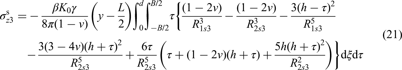
For sidewall ③ of the foundation pit, which is also adjacent to the subway tunnel, the horizontal additional stress


For sidewall ④ of the foundation pit, which lies adjacent to the subway tunnel, a unit normal force βK0γτdξdτ applied at a point (ξ, τ) induces horizontal additional stress


After excavation is completed, the total horizontal and vertical additional stresses at any point (L1, y, h) along the longitudinal axis of the shield tunnel structure, resulting from stress release at the pit bottom and the three adjacent sidewalls, can be determined based on the principle of superposition and are expressed as follows:


Tunnel located below the foundation pit
As illustrated in Figure 3, when the tunnel is located beneath the foundation pit, both pit bottom unloading and stress release from all four sidewalls contribute to the longitudinal forces acting on the tunnel structure. The additional stresses induced by pit bottom unloading are calculated using equations (12) and (13). Those resulting from sidewalls ①, ③, and ④ are obtained from equations (16), (17), (20), (21), (24), and (25), respectively. For sidewall ②, which is also adjacent to the subway tunnel, a unit normal force βK0γτdηdτ applied at a point (η, τ) induces horizontal additional stress


Relative position diagram of the tunnel located beneath the foundation pit.
After excavation is completed, the total horizontal additional stress


Calculation of tunnel structural stiffness
The structure of a subway shield tunnel typically comprises multiple precast segments connected by bolts, resulting in numerous longitudinal joints. To enable the calculation of longitudinal displacement and deformation, a structural simplification along the tunnel axis is generally required. Three primary longitudinal models are commonly used for this purpose: the beam-joint model, the beam-spring model, and the longitudinal equivalent continuous model. Among these, the longitudinal equivalent continuous model is the most widely adopted due to its balance between accuracy and computational efficiency. In this model, the equivalent flexural stiffness of the tunnel, denoted as (EI)eq, is typically calculated using the following expression:

Calculation of displacement in existing tunnels induced by foundation pit excavation
Establishment of the tunnel deformation equation
When calculating the displacement of a tunnel structure induced by additional stresses, the tunnel structure can be idealized using the Winkler, Pasternak, or Kerr foundation models. Among these, the Winkler foundation model—characterizing soil–structure interaction through discrete elastic springs—has been widely employed in tunnel deformation analysis due to its computational efficiency and acceptable accuracy under certain conditions.30,32 The assumption of negligible shear deformation is generally valid for shield tunnels, particularly when the influence zone of the excavation is significantly longer than the tunnel diameter and bending dominates the deformation behavior. This assumption is supported by studies such as Huang et al. 3 and Qiu et al., 30 which demonstrated that excavation-induced tunnel responses are primarily governed by bending effects in stiff to moderately soft soils. Given that the shield tunnel diameter is much smaller than the longitudinal extent of the excavation-affected zone, it is reasonable to consider bending deformation as the primary mode, while neglecting shear effects. Accordingly, the Winkler foundation model is adopted in this study to compute longitudinal deformation, where the tunnel is simplified as a homogeneous beam resting on an elastic foundation. By analyzing this beam–foundation interaction, both the deformation profile and internal force distribution along the tunnel axis can be determined. However, the traditional Winkler model—used for evaluating tunnel vertical displacements—does not incorporate the constraint effects of overlying soil layers, which are especially relevant for deeply buried tunnels. In such cases, a soil layer remains between the tunnel crown and the bottom of the foundation pit. Upon excavation unloading, this overlying soil provides an upward restraining force that resists tunnel uplift. Neglecting this constraint can lead to inaccurate deformation predictions. To address this limitation, a double-sided elastic foundation beam model is proposed, as illustrated in Figure 4. This model accounts for the interaction between the tunnel and both the underlying and overlying soil layers, offering a more realistic representation of the longitudinal deformation behavior of shield tunnels subjected to excavation-induced stress changes.

Double-sided elastic foundation beam model.
As shown in Figure 5, the tunnel and surrounding soil in the vertical direction are idealized as a double-sided elastic foundation beam model, in which the soil above and below the tunnel is represented by vertical elastic springs. A differential beam segment of length dy is considered at an arbitrary longitudinal position for force analysis. Following foundation pit excavation, unloading from the pit bottom and sidewalls generates a vertical additional load qv(y) acting on the tunnel, which induces a corresponding vertical displacement ωv(y). This displacement is resisted by the surrounding soil, producing an upward reaction force pv1(y) from the lower soil spring. Simultaneously, the same vertical displacement of the tunnel crown results in a downward reaction force pv2(y) from the upper soil spring. The differential segment is also subjected to an internal shear force Qv and bending moment Mv. Applying vertical force equilibrium and moment equilibrium to the segment yields the following governing equations:


Schematic diagram of force analysis on a differential element.
From equation (37), the following differential equation can be easily derived:

By neglecting higher-order terms in equation (38), the following equation is obtained:

Substituting equation (40) into equation (39) yields:

According to the principles of mechanics of materials, the deflection differential equation for the tunnel beam is given as

Substituting equation (42) into equation (41) yields:

Based on the deformation compatibility conditions between the tunnel structure and the surrounding upper and lower soil layers, the following can be obtained:


If the vertical equivalent subgrade reaction coefficient is denoted as Kv, it is expressed as

Then, equation (46) can be transformed into

Equation (48) describes the vertical displacement behavior of the subway tunnel. The vertical additional load qv(y) is determined by multiplying the total vertical additional stress—calculated using equation (29) or (35)—by the external diameter of the tunnel. Following a similar procedure, the governing equation for horizontal displacement of the tunnel can also be derived:

By solving equations (48) and (49), the vertical and horizontal displacements of the tunnel can be obtained. Given the suitability of the finite-difference method (FDM) for numerical implementation, it is adopted in this study to analyze the corresponding tunnel beam model. The fundamental principle of the FDM is to replace differential equations and their associated boundary conditions with discrete difference equations, thereby converting the original boundary value problem into a system of linear equations, which substantially reduces computational complexity. For a function y = f(x), the central difference approximation is expressed as follows:

The tunnel beam model satisfies the following governing equation in the vertical direction:


The tunnel foundation beam is discretized into n segments, with nodes numbered sequentially from 1 to n + 1. Each beam segment is defined by two adjacent nodes, such that the i-th segment spans from node I to node i + 1, and its length is denoted as Li. At the midpoint of each segment, the differential equation given in equation (54) must be satisfied. Using the central difference method, the i-th beam segment yields the following system of linear equations:

For all n beam segments, systems of linear equations similar to that expressed in equation (55) are established. Considering that both the shear force and bending moment at the two ends of the tunnel foundation beam are zero, the following boundary conditions are applied:
By simultaneously solving the system of linear equations for all beam segments (equation (55)) along with the boundary conditions (equation (56)), the deflection, rotational angle, bending moment, and shear force of the tunnel foundation beam can be determined. The solution procedure for the beam's horizontal behavior follows a similar finite difference approach as that used in the vertical direction.
Construction of a real-time prediction system
Principles of the real-time prediction system
As discussed in the Section “Derivation of analytical solution,” the accuracy of additional stress calculations on the tunnel structure is strongly influenced by the computed unloading stresses at the pit bottom and sidewalls. The key parameter governing bottom unloading stress is the initial residual stress coefficient α0, while sidewall unloading stress is primarily affected by the side unloading reduction coefficient β. In calculating tunnel displacement induced by these additional stresses, three structure–soil interaction parameters play a critical role: the longitudinal bending stiffness reduction coefficient λ of the shield tunnel, the horizontal subgrade reaction modulus per unit width kh, and the vertical subgrade reaction modulus per unit width kv. These five parameters directly influence the reliability of the analytical solution. However, no standardized method currently exists for their accurate determination. Therefore, precise estimation of these parameters is essential to ensure the applicability of the proposed analytical approach in practical engineering scenarios.
This study integrates field monitoring data with an inverse analysis approach to dynamically identify the values of five key parameters in real time. These inverted parameters, together with the planned excavation depth for the next stage, are substituted into the analytical model to predict tunnel displacements in real time, thereby forming the core of the real-time prediction system developed herein. The principle of this system is illustrated in Figure 6. For each excavation depth during the current stage, the orthogonal design method is first employed to generate combinations of the five parameters. For each combination, the proposed analytical solution is used to compute the corresponding tunnel displacements at monitoring points. These displacement values serve as inputs, while the associated five parameters act as outputs, forming the training dataset for a BP neural network. The BP neural network is trained on this dataset to establish the mapping relationship between tunnel displacements and the corresponding parameter values. Once trained, the network can infer the five parameters from measured tunnel displacements at the current excavation stage. These real-time inverted parameters, combined with the next-stage excavation depth, are then used in the analytical model to predict tunnel displacements at the corresponding monitoring points.

Principle diagram of the real-time prediction system.
Overview of BP neural network principles
The BP neural network, a feed-forward neural network trained via error BP, is organized in a hierarchical structure comprising an input layer, one or more hidden layers, and an output layer.44,45 The number of input nodes corresponds to the number of monitoring points for horizontal and vertical displacements, while the number of output nodes is equal to the number of parameters to be predicted—five in total. A trained BP neural network establishes a highly nonlinear mapping between the input and output spaces. The learning process involves two stages: forward propagation and backward propagation. In forward propagation, input data is transmitted from the input layer through the hidden layers to the output layer, where each layer only affects the subsequent one. If the predicted output deviates from the expected result, the network enters the backward propagation stage. During backward propagation, the error signal is propagated in reverse through the network layers, and the connection weights are iteratively adjusted to minimize the prediction error. These two processes are repeated until the system error converges below a predefined threshold. Upon successful training, the network stabilizes with a set of weights that yield sufficiently accurate predictions.
Due to differences in dimensions and large variations in magnitude among the five parameters used for real-time prediction, directly using unprocessed data to train the BP neural network may lead to significant prediction errors. To address this issue, data preprocessing is required prior to network training. Common preprocessing techniques include standardization, rescaling, transformation, and proportional scaling.47,48 In this study, proportional scaling is adopted, in which all sample data are normalized to the range [0.1, 0.8]. The normalization formula is given as follows:

The BP neural network effectively addresses the parameter inversion problem by capturing complex, nonlinear relationships between displacement monitoring data and the governing mechanical parameters. In contrast to traditional optimization algorithms, the BP network can accommodate irregular displacement trends and learn from diverse input–output patterns, enabling the dynamic estimation of key parameters (α0, β, λ, kh, and kv). During the training phase, synthetic datasets are generated using orthogonal combinations of the five parameters to simulate a wide range of deformation scenarios, thereby enhancing the network's generalization capability. Once trained, the network maps real-time monitoring data to the corresponding parameter space, enabling accurate and efficient real-time inversion.
Engineering application
Project overview
The foundation pit of Gubei Road Station on Shanghai Metro Line 15 is oriented in the north–south direction, with its west side adjacent to the operational tunnel of Shanghai Metro Line 10. The relative positions and geometric dimensions of the foundation pit and the adjacent tunnel are summarized in Table 1. The site's geological conditions are relatively homogeneous and are predominantly composed of clay. The retaining structure consists of 1200 mm-thick diaphragm walls extending to a depth of 42 m. A total of eight support levels are installed along the depth of the foundation pit: the first and fifth levels are reinforced concrete struts, while the second, third, fourth, sixth, seventh, and eighth levels are steel struts. The vertical distances of these support levels from the pit bottom are 29.5, 25.8, 22.1, 18.4, 14.7, 11.0, 7.3, and 3.6 m, respectively.
Relative positional relationship between excavations and tunnels, and dimensions of the excavation geometry.

As shown in Figure 7, vertical displacement monitoring points were installed at 5 m intervals along the tunnel crown within the excavation-influenced section of Line 10. For the extended sections on both sides, additional points were arranged at 10 m intervals within a total range of 50 m (20 m on one side and 30 m on the other), resulting in a total of 12 vertical displacement monitoring points. The monitoring layout for horizontal displacement at the crown shoulders and vertical displacement at the crown was colocated at the same sections.

Layout of tunnel displacement monitoring points.
Application of the real-time prediction system
To verify the reliability of the real-time prediction system proposed in this study, the system was applied to predict the displacement of Shanghai Metro Line 10 induced by the excavation at Gubei Road Station on Metro Line 15, using field monitoring data as input. The predicted results were then compared against the measured data to evaluate the accuracy and validity of the proposed approach.
In the calculations, the elastic modulus of the tunnel concrete segments, Ec, was set to 3.45 × 10⁷ kPa. The inner diameter of the tunnel was 5.20 m, and the outer diameter was 6.20 m. The Poisson's ratio of the soil was taken as 0.30, the unit weight of the soil was 19.00 kN/m3, and the coefficient of earth pressure at rest, K0, was set to 0.58. For the generation of training samples for the BP neural network, the range of values for the five parameters was as follows: the initial residual stress coefficient α0 ∈ [0.0, 1.0], the excavation-side unloading reduction coefficient β ∈ [0.0, 1.0], the reduction coefficient of the longitudinal flexural rigidity of the shield tunnel structure λ ∈ [0.1, 0.9], the horizontal subgrade reaction coefficient per unit width kh ∈ [3.0 × 10³, 1.5 × 10⁵] kN/m3, and the vertical subgrade reaction coefficient per unit width kv ∈ [5.0 × 103,1.0 × 105] kN/m3.
Real-time tunnel displacement prediction was conducted using the system illustrated in Figure 6. A comparison between predicted and measured vertical and horizontal displacements is presented in Figure 8(a) and (b), respectively, while the corresponding prediction errors are shown in Figure 8(c) and (d). As observed in Figure 8(a) and (c), the predicted vertical displacement closely matches the measured data under most conditions. However, larger deviations are evident when the displacement trend undergoes reversal, with a maximum error reaching 21.82%. Despite this, the predictive accuracy remains within acceptable limits for engineering applications. In contrast, Figure 8(b) and (d) shows that the predicted horizontal displacements exhibit even closer agreement with measured values, with a maximum error of only 1.95%. This improved accuracy can be attributed to the absence of significant trend reversals in horizontal displacement during the monitored excavation stages. Additionally, the results reveal that when excavation occurs adjacent to the tunnel, the induced horizontal displacement tends to exceed the vertical displacement in magnitude. This suggests that greater emphasis should be placed on horizontal displacement control during construction. In summary, the comparison results presented in Figure 8(a) and (b) confirm the high predictive accuracy of the proposed real-time prediction system for excavation-induced tunnel deformation. Notably, the system performs particularly well in predicting horizontal displacement, demonstrating strong model stability and low sensitivity to abrupt changes in construction conditions.

Comparison between predicted and measured displacements: (a) vertical displacement; (b) horizontal displacement; (c) vertical displacement error; and (d) horizontal displacement error.
Steps 1 to 5 correspond to the upper excavation stages of the foundation pit. During this phase, the observed upward vertical displacement reflects the structural response to the release of overburden pressure, while horizontal displacement gradually increases. The predicted results show strong agreement with the measured data throughout these stages. Steps 6 to 8 represent the excavation of the main deep foundation pit, during which substantial stress redistribution occurs, leading to more pronounced structural deformation. In this phase, vertical displacement follows a decreasing-then-increasing trend, and prediction errors become more noticeable. At step 9, due to the application of counteracting forces from support installation or partial backfilling, a slight uplift of the tunnel is observed. Despite these dynamic changes, the model continues to capture the overall displacement trend with reasonable accuracy. These results indicate that while the system maintains high predictive performance overall, its accuracy may slightly decline during critical excavation phases characterized by rapid and nonlinear stress redistribution.
The prediction error increases when the displacement trend reverses, which can be attributed to the intrinsic nonlinear characteristics of parameter inversion using the BP neural network. This method relies on the mapping between monitoring point displacements and mechanical parameters; however, during trend reversals, small fluctuations in displacement can lead to disproportionately large variations in predicted parameters, thereby reducing the model's predictive stability. This phenomenon is particularly pronounced when excavation-induced loading conditions change rapidly, challenging the network's ability to generalize from prior training data. Future work may incorporate hybrid inversion strategies or adaptive learning techniques to enhance robustness under non-monotonic displacement conditions.
A sensitivity analysis was performed to assess the directional influence of key parameters within the prediction model. The results reveal that vertical displacement predictions are particularly sensitive to variations in α0 and kv, especially during the early excavation stages when uplift effects dominate the tunnel response. In contrast, horizontal displacement predictions exhibit greater robustness and are primarily influenced by kh and β. This is attributed to the relatively monotonic nature of lateral soil movements, which enhances the BP neural network's inversion accuracy for parameters governing horizontal behavior.
Conclusion
This study presents a real-time prediction system for excavation-induced tunnel deformation by coupling an analytical solution with machine learning-based parameter inversion. The analytical component is developed from a two-stage stress redistribution model and a double-sided elastic foundation beam theory, while a BP neural network is employed for dynamic inversion of key parameters based on field monitoring data. The main findings are summarized as follows:
A novel analytical framework for predicting tunnel deformation was established, incorporating Mindlin's solution for stress redistribution and beam theory to model tunnel response. The integration of a BP neural network enables real-time parameter inversion, thereby improving adaptability to varying geotechnical conditions. In practical applications, when excavation occurs adjacent and parallel to the tunnel axis, vertical displacement exhibits a nonlinear pattern, while horizontal displacement dominates. Therefore, horizontal movement should be prioritized in deformation control strategies to ensure tunnel safety. The predicted displacements show strong agreement with field measurements, with maximum errors of 21.82% for vertical and 1.95% for horizontal displacements. The system demonstrates high overall predictive accuracy, with minor performance degradation observed during displacement trend reversals due to nonlinear parameter sensitivity. The proposed system offers a practical and computationally efficient approach for real-time tunnel deformation prediction and provides valuable support for proactive decision-making in excavation risk management.
Footnotes
Acknowledgements
Professor Peijun Guo from McMaster University in Canada, provided the language help in this work; the help is greatly appreciated.
Funding
The authors disclosed receipt of the following financial support for the research, authorship, and/or publication of this article: This work was supported by the Science and Technology Research Project of Chongqing Municipal Education Commission (No. KJQN202403227), the Construction and scientific research project of the Zhejiang Provincial Department of Housing and Urban–Rural Development (No. 2021K126), and the Scientific Research Project of China Construction 4th Engineering Bureau (Nos. CSCEC4B-2025-KTA-18, SCEC4B-2025-KTB-9). The financial support is greatly appreciated.
Declaration of conflicting interests
The authors declared no potential conflicts of interest with respect to the research, authorship, and/or publication of this article.
Appendix 1
List of symbols used in this study