
Abstract
In this paper, a simple chain suspension catenary model is constructed. The acting force of pantograph is reduced to a displacement loading. The stress and fatigue life of railway catenary dropper incorporating displacement loading and fluctuating wind load are studied. Through writing a MATLAB code, the vibration equation of the dropper is used to calculate its stress under different conditions using a finite difference method, combining with the initial boundary value conditions obtained by the response equations of the contact wire. Based on the dropper stress, its fatigue life can be obtained. The results show that under the 250 km/h train speed, the stress change process of the dropper experiences three stages: immediate rebound, attenuation vibration, and bending compression. Dropper Ⅳ is most likely to break in a span. Compared with dropper Ⅳ, the fatigue life of dropper Ⅰ is 11 times, and those of droppers Ⅱ, Ⅲ, and Ⅴ are about 2.5 times. Compared with no wind, the fatigue lives of droppers Ⅰ–Ⅳ are reduced by approximately three times at a wind speed of 25 m/s. This work provides a powerful means for the study of dropper stress under actual working condition.
Introduction
For high-speed railways, power transmission is completed by sliding contact between pantograph and catenary. The stable contact is directly related to the current collection quality of train, which affects the operating efficiency and safety. Therefore, it is very important to ensure the good contact. Otherwise, it may cause a series of failures such as contact wire breakage, which causes a serious threat to the safety of railway transportation.
Due to the high cost of constructing actual lines to conduct experiments, computer simulation is usually used to construct the pantograph–catenary dynamics models. At present, the common models include mass reduction, rigid-flexible hybrid, and full-flexible body models.1–3 The main methods include finite difference, finite element, and modal analysis methods.4–7 Many scholars have studied the parameter influences on the state of pantograph.8–10 At the same time, they have also studied the influences of external excitation. Among them, the external excitation includes the actions of the pantograph11–12 and the external environment.13–15 Currently, the characteristics of the catenary system are mainly concerned. However, the research on the key components of catenary, especially dropper, is relatively few. Dropper stress is directly related to its fatigue life, which affects the stability and safety of the catenary system.
He et al. 16 used a sinusoidal force to study the effects of moving load on dropper stress. A sinusoidal force deviates from the actual working condition and it is commonly used in laboratory simulation tests. The actual moving load is very difficult measured due to a high voltage of the catenary system. In the early stage, based on the noncontact measurement technology, our research group obtained the uplift displacement of the connection between dropper and contact wire. Therefore, this paper applies the displacement instead of moving load to study dropper stress and further calculate its fatigue life. Then, the fluctuating wind load is added to investigate the effects on dropper stress and fatigue life.
This paper is structured as follows: “Contact wire’s response equation” section deduces contact wire's response equation under displacement loading and fluctuating wind load based on a simple chain suspension catenary model; “Calculation of dropper stress” section 3 gives dropper stress equation and numerical method; “Results” section shows the numerical results of dropper stress and fatigue life; “Discussion” section discusses effects of fluctuating wind load on dropper stress and fatigue life, including effects of wind speed and wind attack angle. We also outline the model limitations and future work in this section; finally, we draw up conclusions in “Conclusion” section.
Contact wire's response equation
Firstly, the section constructs a simple chain suspension catenary model. At the same time, the measured uplift displacement is converted to the load (“Catenary model” section). Then, the vibration equations of contact wire under displacement loading (“Response equation under displacement loading” section) and fluctuating wind load (“Response equation under fluctuating wind load” section) are, respectively, deduced.
Catenary model
To simplify the analysis, the action of pantograph is reduced to a vertical force on the contact wire. Figure 1 depicts a simple chain suspension catenary model. The span of the catenary is 50 m, and the distance between two adjacent droppers is 10 m. The lengths of droppers Ⅰ and Ⅴ are 1.6 m, 17 and the lengths of droppers Ⅱ and Ⅳ can be obtained by a parabolic method as 1.295 m, and the dropper Ⅲ length is 1.2547 m.

Simple chain suspension catenary model.
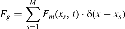
In Figure 1, c represents the distance between the origin O and the initial position of the loading action. N represents the tension. F is the pantograph–catenary contact force, which changes with time t and position x. F can be expressed as
In this paper,

According to the literature,
19
the following can be written:


The measured uplift displacement.
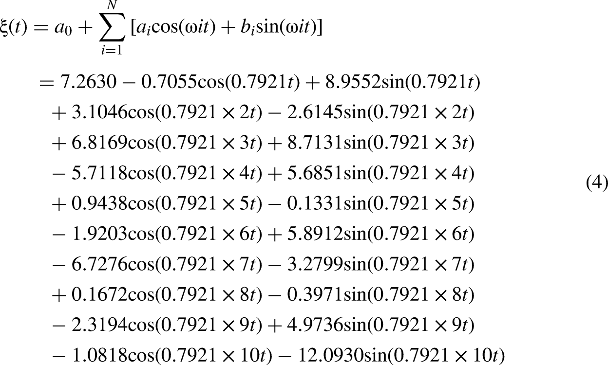
Data points are extracted from Figure 2, and the Fourier function is fitted to the data points by MATLAB. The Fourier fitting (it is based on the Fourier series, which states that any periodic function can be represented as a sum of sine and cosine functions with different frequencies) results are shown in Figure 3.

The fitting result.
The fitting result is written as follows:
Response equation under displacement loading
To obtain the response equation of contact wire under displacement loading, we treat the contact wire as an equal-sectional beam and write its free vibration equation:

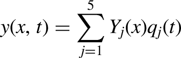
The time and space separation processing of the displacement function is performed, that is,


Then, there is:


Since the effect of higher orders is negligible, we only compute the first five orders. Therefore, the response is obtained as follows:
Response equation under fluctuating wind load
Since fluctuating wind is correlated with time and space, it can be discretized as an external excitation. To set up a fluctuating wind field, we select fluctuating wind points at equidistance. In order to reduce the error caused by the discretization of fluctuating wind load, the interval between wind points should not be too large. At the same time, it should not also be too small due to computational efficiency. Through the test, we finally take a wind point every 10 m and a total of 6 wind points, as shown in Figure 4.

Simulation points of fluctuating wind field.
The vertical fluctuating wind load acting on the s-th wind point can be expressed:

Therefore, the discrete vertical fluctuating wind load
Thus, the forced vibration equation under the combination of displacement loading and fluctuating wind load is written:


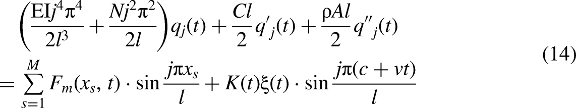


Similarly, we take the first five orders. Therefore, the response is the following:

Parameters of the contact wire.

The section deduces contact wire's response equation under displacement loading and fluctuating wind load based on a simple chain suspension catenary model. It provides the boundary conditions of dropper stress calculation in the following section.
Calculation of dropper stress
Stress equation
To obtain stress equation of dropper, we make the force analysis in Figure 5.

Force analysis on dropper.
In Figure 5,
Let

Through the force analysis, the following equation can be obtained:

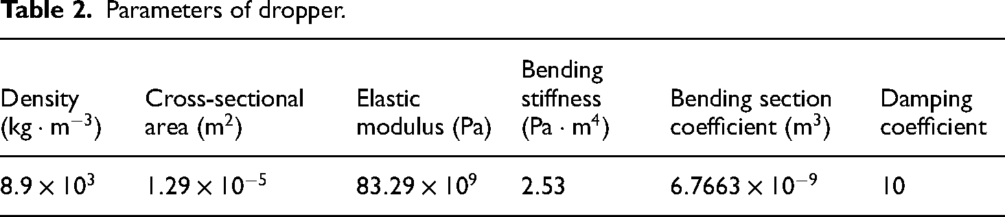
The relevant parameters need to be given to calculate the dropper stress, as shown in Table 2.
Parameters of dropper.
Initial boundary value conditions
We uniformly write the initial boundary value conditions as follows: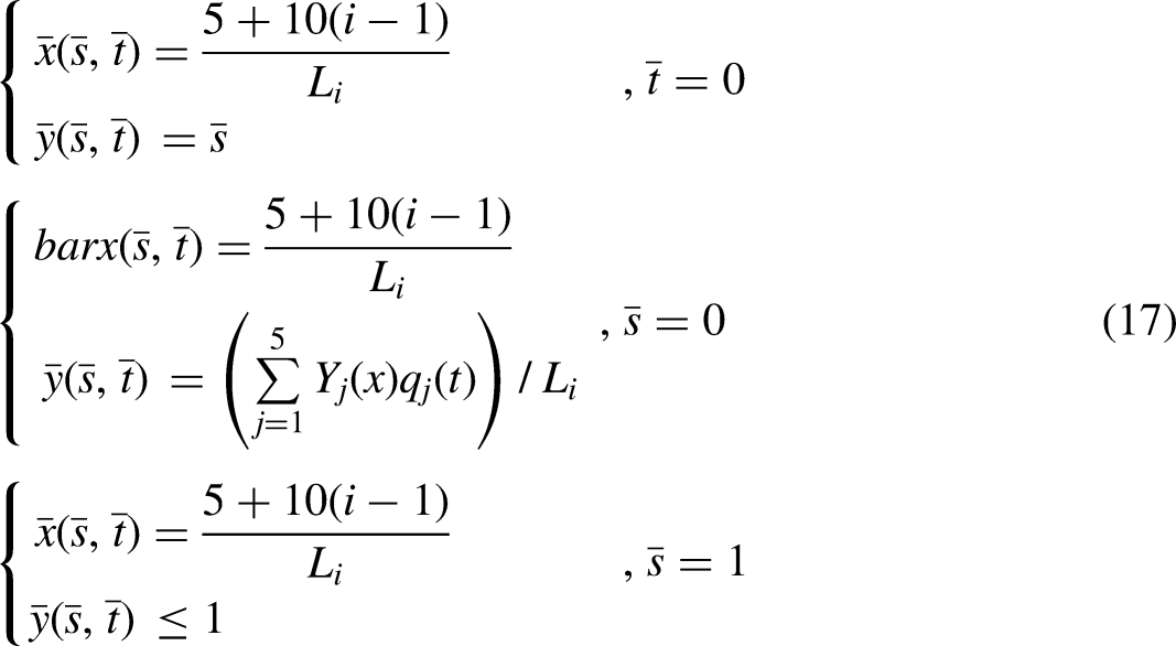
Numerical method
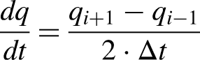
The finite difference method (it approximates derivatives in a differential equation by using finite differences between values at discrete points) is used to obtain the numerical solution, and the following steps are given:
Discretizing the dropper into n units of equal length. Considering the calculation accuracy and time, the value of n is 32, and the value of dimensionless time step is Selecting the finite difference scheme. The partial differential approximation of the dimensionless variables in the system of equations is expressed as follows: By substituting the expression of the difference scheme in step (2) into equation (15), the difference equations can be obtained.
The section gives dropper stress equation and numerical method. The stresses under different conditions can be obtained by writing a MATLAB code. The results are shown in the following section.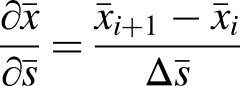


Results
Dropper stress and fatigue life under the displacement loading
The results are shown when the high-speed train runs at 250 km/h from dropper Ⅲ to the right and only the displacement loading is considered, that is, the wind speed is zero. Figure 6 shows dropper I stress variation, and its maximum tensile stress is 390 MPa. The time is very short to reach the maximum stress, and there is an obvious periodicity in the vibration process. The stress change in 0–8 s experiences many cycles. In order to facilitate observation, we enlarge one of the cycles. It is obvious that the time-dependent stress change in a period goes through immediate rebound, attenuation vibration, and bending compression stages.

Dropper Ⅰ stress with time.
The stress change of dropper II is shown in Figure 7, and its maximum tensile stress value is 594 MPa. The stress change also goes through three stages in one cycle. However, due to the difference in the positions of droppers Ⅰ and Ⅱ, their stress changes show different characteristics. Compared with dropper Ⅰ, dropper Ⅱ has the higher maximum tensile stress and the lower maximum compressive stress. This is because there is energy loss when the vibration of the contact wire propagates, so that the vibration degree of dropper II is stronger.

Dropper Ⅱ stress with time.
The shown dropper Ⅲ stress in Figure 8 depicts that its maximum tensile stress value is 656 MPa. Compared with droppers Ⅰ and Ⅱ, dropper Ⅲ has a similar stress change. However, it has the higher maximum tensile stress, and the time is shorter to reach the maximum tensile stress. The reason is that droppers I and II are far away from the position where the load begins to act. The wave propagation takes time, and there is energy loss, which makes the vibration degree of droppers I and II smaller. Thus, the maximum tensile stress occurrences of droppers I and II spend the longer time.

Dropper Ⅲ stress with time.
Figure 9 shows that dropper Ⅳ has the maximum tensile stress of 833 MPa. Dropper Ⅳ has the higher maximum tensile stress in contrast to droppers I, II, and III. Although the catenary structure is symmetrical, the dropper stress change in a span is not symmetrical because we apply the load to the contact wire and move it to the right for a period of time. Compared with dropper Ⅲ, the maximum tensile stress occurrence of dropper Ⅳ spends the shorter time. The reason is that the process to reach the maximum tensile stress needs to accumulate the energy generated by the load. When the load starts to move, the energy of dropper Ⅲ gradually decreases, and that of dropper Ⅳ begins to increase for a period of time and then gradually decreases.

Dropper Ⅳ stress with time.
Figure 10 indicates that the maximum tensile stress of dropper V is 646 MPa. Dropper V also experiences immediate rebound, attenuation vibration, and bending compression stages. However, compared with dropper Ⅳ, it has a lower maximum tensile stress.

Dropper Ⅴ stress with time.
Next, we calculate the dropper fatigue life. First, we need to obtain the S-N (Stress-Number of cycles) curve of the dropper. According to the calculated stress history of the dropper, it can be found that the stress amplitude reaches 700 MPa or even more. The stress amplitude in the S-N curve parameters obtained by Qu 21 reaches a maximum of 2000 MPa, which meets our usage requirements. Thus, we use Qu's data to carry out the power function curve fitting, as shown in Figure 11.

The fitting results.
The double logarithmic S-N curve obtained by Basquin equation (
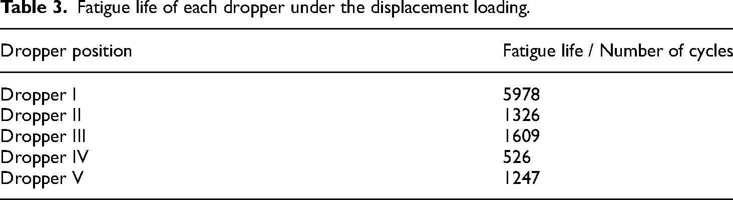
Then, we select Palmgren–Miner rule (linear damage accumulation method) to calculate the dropper fatigue life. The rule is widely used due to concise calculation and easy-to-understand theory. Certainly, there are other rules, such as Manson (bilinear damage accumulation method) and Macro–Starkey (nonlinear damage accumulation method).22,23 They may provide more accurate predictions under certain conditions. However, these theories often require more complex data inputs and more advanced computational methods. For example, nonlinear damage accumulation method typically requires complex models that consider material strength changes and damage evolution during the damage process, which increases the complexity and uncertainty of nonlinear theory in practical applications. Table 3 shows the results under the action of displacement loading. We find that dropper Ⅳ has the shortest fatigue life.
Fatigue life of each dropper under the displacement loading.
Effects of wind speed on dropper stress and fatigue life
The results are displayed when the displacement loading and fluctuating wind load are considered together. After applying the fluctuating wind load, the dropper stress distributions under different wind speeds and initial wind attack angles do not show obvious differences from those under only the displacement loading. Therefore, the stress distributions under other conditions are not displayed here. We analyze the effects of wind speed on the dropper stress and fatigue life when the initial wind attack angle is kept constant at 30°. We calculate the maximum tensile stress and fatigue life of each dropper under the 0, 15, 20, and 25 m/s wind speeds, respectively.
Figure 12 displays the variations of the maximum tensile stresses under different wind speeds. Dropper Ⅳ has the highest maximum tensile stress no matter when there is no wind or a certain wind speed. After applying the fluctuating wind with the speeds of 15, 20, and 25 m/s, the increase in wind speed significantly makes the maximum tensile stresses of droppers Ⅲ and Ⅳ increase. Dropper Ⅱ also has the obvious maximum tensile stress change, but it decreases with the increasing wind speed from 20 to 25 m/s. However, droppers Ⅰ and Ⅴ gently change in the maximum tensile stress. Compared with no wind, dropper Ⅴ has the lower maximum tensile stress when the wind speed is 15 m/s. It is found that droppers Ⅱ, Ⅲ, and Ⅳ have the higher maximum tensile stresses in contrast to droppers Ⅰ and Ⅴ when there is a fluctuating wind load.

Maximum tensile stress of dropper under different wind speeds.
Figure 13 suggests that the fatigue life of dropper Ⅳ is shorter than those of other droppers whether there is wind or no wind. Compared with no wind, except for dropper Ⅴ, the fatigue lives of other droppers decrease when the 15 m/s fluctuating wind is applied. The fatigue life of each dropper shows a decreasing trend when the wind speed increases. It is found that droppers Ⅱ, Ⅲ, and Ⅳ have shorter fatigue lives in contrast to droppers Ⅰ and Ⅴ when there is fluctuating wind load.

Dropper fatigue life under different wind speeds.
Effects of wind attack angle on dropper stress and fatigue life
In order to explore the effects of wind attack angle on the dropper stress and fatigue life, we fix the 20 m/s wind speed and respectively calculate the maximum tensile stress and fatigue life of each dropper under the 30°, 60°, and 90° initial wind attack angles.
Figure 14 shows that dropper Ⅳ has the highest maximum tensile stress. With the increasing wind attack angle from 30° to 60°, other droppers significantly have increased maximum tensile stresses, except for dropper Ⅱ. With the increasing wind attack angle from 60° to 90°, other droppers have the increased maximum tensile stresses, except for dropper Ⅴ. Compared with the 30° wind attack angle, the 90° angle makes the maximum tensile stress of each dropper increase. On the whole, droppers Ⅰ, Ⅲ, and Ⅳ have the increased maximum tensile stresses when the wind attack angle increases. However, droppers Ⅱ and Ⅴ have not an obvious change trend. Compared with droppers Ⅰ and Ⅴ, droppers Ⅱ, Ⅲ, and Ⅳ always have the higher maximum tensile stresses when the wind attack angle is changed.

Maximum tensile stress of dropper under different wind attack angles.
Figure 15 shows the fatigue life changes of the droppers under different wind attack angles. When the fluctuating wind with different wind attack angles is applied, dropper Ⅳ has the shorter fatigue life than other droppers. On the whole, the fatigue lives of droppers Ⅰ–Ⅳ decrease with the increasing wind attack angle. However, the increasing wind attack angle from 30° to 60° slightly makes the fatigue life of dropper Ⅴ increase. The increasing wind attack angle from 60° to 90° makes the fatigue life of dropper Ⅴ decrease. Compared with droppers Ⅱ, Ⅲ, and Ⅳ, droppers Ⅰ and Ⅴ always have longer fatigue lives when the wind attack angle is changed.

Dropper fatigue life under different wind attack angles.
The numerical results of dropper stress and fatigue life are shown in the section. Based on the results, we discuss the effects of the loads on dropper stress and fatigue life in the following section.
Discussion
In this paper, the measured uplift displacement is taken as the initial load, and the dynamic behavior is simulated. When the train moves forward, the stress variation process of each dropper goes through immediate rebound, attenuation vibration, and bending compression stages. Under the action of the load, the droppers produce vibration, which propagates to the left and right. In the propagation process, the wave energy is lost, and the wave propagation and energy accumulation take time. Therefore, each dropper has a different maximum tensile stress and occurrence time. Dropper Ⅳ has the highest maximum tensile stress and the shortest fatigue life. In contrast to dropper Ⅳ, the fatigue life of dropper Ⅰ is 11 times, and those of droppers Ⅱ, Ⅲ, and Ⅴ are about 2.5 times.
When the fluctuating wind load is applied, dropper Ⅳ still has the highest maximum tensile stress and the shortest fatigue life under different wind speeds and wind attack angles. According to Figure 12, we find that droppers Ⅱ, Ⅲ, and Ⅳ have significant maximum tensile stress changes, however, droppers Ⅰ and Ⅴ have smooth changes. Therefore, in the same span, droppers Ⅱ, Ⅲ, and Ⅳ are more sensitive to the fluctuating wind load, which is good agreement with the findings of Wu et al. 19 Compared to no wind, the 15 m/s fluctuating wind makes dropper V have the lower maximum tensile stress and the longer fatigue life. Additionally, the fatigue lives of droppers Ⅰ–Ⅳ are reduced by approximately three times at a wind speed of 25 m/s. Generally, the fatigue life of each dropper basically decreases with the increasing wind speed. It shows that the fluctuating wind load has adverse effects on the droppers, and the higher the wind speed, the more serious the fatigue damage caused by the fluctuating wind to the droppers, which is consistent with the results of Song et al. 24 According to Figures 14 and 15, droppers I–Ⅳ have the increased maximum tensile stresses and the decreased fatigue life with the increasing wind attack angle. However, the fatigue life variations of dropper V under different wind attack angles are not obvious. Overall, we cannot ignore the angle change in the mechanical investigation of the droppers. The wind speed and the wind attack angle are the critical factors influencing the wind-induced vibration behavior of catenary. 25
Under the fluctuating wind load, droppers Ⅱ, Ⅲ, and Ⅳ have higher maximum tensile stress and shorter fatigue lives in contrast to droppers Ⅰ and Ⅴ, indicating that in the same span, droppers Ⅱ, Ⅲ, and Ⅳ are more prone to fatigue fracture than droppers Ⅰ and Ⅴ. Therefore, in the daily maintenance of the catenary, we should focus on droppers Ⅱ, Ⅲ, and Ⅳ. According to the analysis of Chen, 26 the dropper near the midpoint of a span has worse fatigue resistance than the dropper near the anchor point, which is basically consistent with our results. Furthermore, our results indicate that dropper Ⅳ is the most prone to fracture in a span. This is consistent with the statistical results of Yu et al. 27 Thus, the model used in this study has higher accuracy and reliability compared to Chen's model when the fatigue life is predicted.
It is practical to implement additional structural reinforcements for droppers in regions with high wind speeds, given the potential fatigue issues outlined in the study. The findings about dropper sensitivity to wind loads can be applied to similar structures, such as power lines or suspension bridges. It should be noted that the analysis does not consider possible manufacturing inconsistencies or installation errors that could also influence failure rates.
This work provides a new idea for the mechanical characteristics of dropper. However, it only considers the vertical force of wind load. The vertical amplitude of contact wire increases with wind speed under horizontal wind. 28 Thus, the horizontal force might change the displacement boundary conditions and furthermore influence dropper stress. In the subsequent study, the horizontal force of wind load will be included to further investigate the effects of wind load on the dynamic characteristics of dropper.
Based on the above discussion, we draw conclusions in the following section.
Conclusion
This work establishes a catenary model to study the dropper stress and fatigue life under the action of displacement loading and fluctuating wind load, and the effects of different wind speeds and wind attack angles are also analyzed. The following points can be concluded.
In the case of no wind, when the train is moving forward, the dropper stress change process goes through immediate rebound, attenuation vibration, and bending compression stages. Each dropper has a different maximum tensile stress and occurrence time. Compared with dropper Ⅳ, the fatigue life of dropper Ⅰ is 11 times, and those of droppers Ⅱ, Ⅲ, and Ⅴ are about 2.5 times. Therefore, dropper Ⅳ in a span is most likely to break. The fluctuating wind with a high speed has adverse effects on the droppers. Under the fixed wind attack angle, the higher the speed, the more serious the fatigue damage to the droppers. Especially, compared with no wind, the fatigue lives of droppers Ⅰ–Ⅳ are reduced by approximately three times at a wind speed of 25 m/s. Under the fixed wind speed, the greater the wind attack angle is, the more unfavorable the effects of fluctuating wind on droppers Ⅰ–Ⅳ. In the same span, compared with droppers Ⅰ and Ⅴ, droppers Ⅱ, Ⅲ, and Ⅳ are more sensitive to the wind load and they are more prone to fatigue fracture.
Footnotes
Acknowledgements
This work is supported by Research Project of China State Railway Group Co., Ltd (N2023G065) and Research Project of China Academy of Railway Sciences Co., Ltd (2023YJ271).
Authors’ contribution
Like Pan and Caizhi Yang wrote the main manuscript text. Xinxin Shen and Fan He made crucial initial contributions to the manuscript, especially for the modelling. Xiaohan Zhu, Yingxin Zhao, and Yuan Yuan made the analysis. Qingyuan Zhao, Qingzhou Meng, Bo Dong, and Xiaoli Guo collected the remaining literature for related approaches and data. All authors reviewed the manuscript.
Data availability
The data used to support the findings of this study are included within the article.
Declaration of conflicting interests
The author(s) declared no potential conflicts of interest with respect to the research, authorship, and/or publication of this article.
Funding
The author(s) received no financial support for the research, authorship, and/or publication of this article.