
Abstract
Composite bolted joints are quite necessary for composite structures connection, which has become the main limit for the use of composites in main load-bearing structures. In this article, a fatigue model of composite bolted joint based on equivalent stress is established by programming in ABAQUS USDFLD subroutine to simulate the progressive failure of composite bolted joints. By introducing three-dimensional Tsai–Hill static failure criterion, equivalent stress is calculated for investigating effects of multiaxial stress on fatigue life. In the subroutine of progressive failure for fatigue model, fatigue life of composite bolted joint and damage state of elements that are meshed in the process of modelling are connected by defining field variable. Different fatigue modes are predicted here by changing stress amplitude and ratio loading, in which simulation results agree well with that obtained in corresponding experiments.
Introduction
With excellent mechanical properties, carbon fibre–reinforced composites are widely used in many engineering structures. So many researchers have studied static failure feature of carbon fibre–reinforced composites, which could be influenced by ply angle, 1 environmental condition 2 and moulding technology.3,4 With broad application of composites, composite structure is more and more complicated, and connection of different composite components becomes essential. Meanwhile, bolted joints are the most widely used in the composite components connection. With the development of composite technology, now composite has been applied in some primary and secondary load-bearing structures. For example, the central wing box of A350 is completely manufactured using composites. Usually, the composite primary load-bearing structure does not take fatigue into consideration due to the excellent fatigue property of composites or full-scale test of composite structure, which is time-consuming, expensive and over design. Therefore, to cut cost and improve reliability of whole service of composites, fatigue characteristic of composites has been considered critically important. Furthermore, study of fatigue of composite bolted joint becomes vital since composite bolted joint is the most common joint in structures.
Composite bolted joint usually consists of two parts – composite laminate and bolt. As is known, the fatigue of joints is mainly determined by the laminate, and the fatigue characteristic of fibre-reinforced composite laminate has aroused many researchers’ interest in the past few decades. Furthermore, investigation of the fatigue of composite laminates can be divided into two types:5 –10 phenomenological mathematical fatigue life model and progressive fatigue damage model. The former is usually adopted to estimate fatigue life based on unidirectional laminate fatigue life experiments, while the latter is used to represent fatigue failure mode of composites. But the laminate in composite bolted joint is under serious stress concentration due to the hole in the laminate. So, the basic research for fatigue failure mechanism of laminate is not good enough. On the contrary, some researchers investigate fatigue failure of laminate with open hole by experimental11 –15 and analytical16 –20 methods. With extensive application of composites, more and more complicated composite structures have appeared, which places the joint in an essential role for the structure. Composite bolted joints are the most common joints applied in composite connection. Based on early studies, the so-called “residual strength and residual modulus”21 –24 are introduced to fatigue analysis of composite bolted joint. Using finite element (FE) software, residual strength and modulus of composite are implemented in the progressive model, and the simulation results show good agreements with the experimental results. In these literatures, modelling of fatigue of composite bolted joint is based on the uniaxial fatigue experiments; however, composites are usually under multiaxial stress state caused by anisotropy and connection of composite which is not compliance with actual situation. Since multiaxial fatigue experiment is quite complicated and time-consuming, multiaxial fatigue behaviour25,26 of composite laminate is investigated based on unidirectional laminate fatigue behaviour, which could potentially make the experiments cost and time-efficient. Campos et al. 27 investigated the fatigue of adhesively bonded epoxy-AA6061T651 joints. In their study, static shear strength was higher than that recommended by the manufacturer for aluminium substrates, but fatigue resistance of the double lap joints was lower than what was suggested by the manufacturer.
Although many researchers have studied the fatigue behaviour of composite bolted joints, the experimental cost in these studies is still expensive. One possible reason is that there are seven residual strengths in the progressive fatigue model, which means that when we use the model, seven residual strengths of laminate must be very clear, otherwise the model cannot predict the failure of the joint. The main objective of this article is to establish an effective engineering fatigue life assessment model for composite bolted joint, which could obviously reduce fatigue experiments by taking multiaxial stress into consideration. It is known that fibre-reinforced composite laminate is anisotropic, resulting in multiaxial stress even if composite laminate is under uniaxial stress. Since the laminate could be connected with other components, the composite laminate in the joint will be under complex stress state caused by joints. Meanwhile, failure mode of the composite is quite complicated due to the components of the composite. So, in this article, a progressive fatigue model is developed to predict multiaxial fatigue life and failure mode of composite bolted joint. In this model, failure mode of joint is carried out by subroutine USDLFD of ABAQUS, where properties of the composite degrade when composites satisfy fatigue failure criterion. Effect of multiaxial stresses on fatigue is realized by equivalent stress which is a normalized parameter calculated by the three-dimensional (3D) Tsai–Hill criterion.
Problem in composite bolted joint
The basic configuration of composite bolted joint is illustrated in Figure 1. The single-lap bolted joint is the most common one to appear in composite connection. Since the open hole is present in the laminate, stress concentration is quite serious even in static load. When the joint is subject to cycle loading, the fatigue of joint is even more complicated. Bolt torque, geometric parameters and loading condition (stress ratio, R) all have significant influence on fatigue of composite bolted joint. Compared with coupon laminate under cycle loading with the bolt or pin existing, when the joint is subjected to tensile–tensile loading, some area around the bolt hole could be under compression, and anisotropy of composite makes the stress state which is multiaxial. However, most fatigue tests of composite are carried out by uniaxial tests. It is very convenient to predict multiaxial fatigue of composites based on uniaxial fatigue experiment.

Composite bolted joint configuration.
To study fatigue mechanism (failure mode) of composite bolted joint, progressive failure model is adopted based on residual strength or stiffness theory by some researchers. But, the residual strength and stiffness experiments are costly and time-consuming. In addition, fatigue failure criterion is usually based on modified static failure criterion within these models. In this article, we use equivalent stress theory and stiffness degradation method to predict multiaxial fatigue failure of composite bolted joint.
Equivalent stress
In metal fatigue research, multiaxial stress is usually converted into equivalent uniaxial stress, and then the fatigue experiments based on uniaxial test could be used in multiaxial fatigue life prediction. In our article, definition of equivalent stress is introduced to the fatigue prediction of composites. First, non-dimensional equivalent stress is defined on the basis of the modified Tsai–Hill static failure criterion. Since the joint has 3D problem, 3D failure criterion is adopted to calculate equivalent stress. Second, for the case of 3D stress, it is expressed as
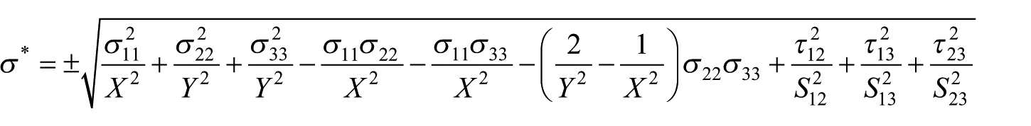
where
Degradation of composite properties
It is necessary to choose proper fatigue failure criterion and material properties degradation to simulate fatigue progressive of composites. As shown in Figure 2, black line is the traditional stiffness degradation curve used in progressive fatigue simulation. Degradation of stiffness or strength is connected with number of loading cycles.

where

Degradation of stiffness.
During the practical application of composites, initiation stiffness degradation of the composite shown in Figure 2 in red line occupies most of fatigue life. In other words, stiffness degradation of the composite is not very obvious. To simplify the fatigue progressive failure simulation, it can be assumed that, as long as the failure of composite does not happen, the stiffness is kept as static stiffness. Once the final fatigue of composite occurs, normalized stiffness changes from one to zero, shown in Figure 2 in green line. Since our fatigue progressive model is established in ABAQUS, the engineering properties of the composite cannot be zero, which will result in convergence problem. Here, 10% of original modulus is chosen as final degraded stiffness.
Fatigue life of composite laminate
Another aspect of fatigue simulation of composite bolted joint is fatigue criterion. Here, fatigue life is used as fatigue failure criterion, and Miner’s accumulation rule is applied for fatigue life calculation. In Palmgren–Miner rule, the accumulated damage,

Failure is predicted when the cumulative damage
Progressive fatigue model
FE model
FE model is meshed by C3D8R element: an eight-node linear brick, reduced integration element. Meshes around the bolt hole are refined to ensure the calculation accuracy. Mechanical parameters are shown in Table 1. The model is loaded by applying a fixed boundary condition to bolt and a sinusoidal cycle loading in the right hand of composite laminate, as shown in Figure 3.
Properties of composite laminate. 28

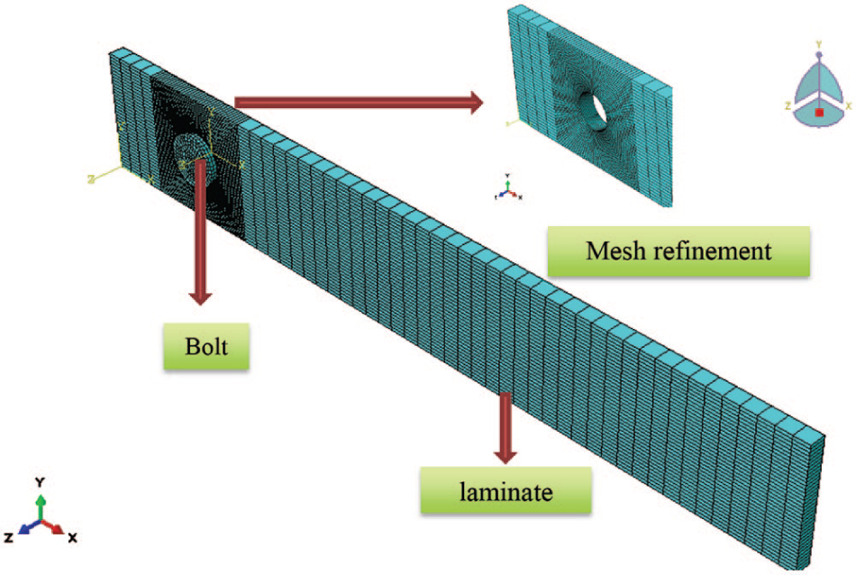
Finite element model of composite bolted joint.
Composite laminates in the joint are made by T300/BMP-316, where the stacking sequence is [45/–45/90/0/–45/0/45/0/90/0]s. Each ply thickness for this laminate is nominally 0.12 mm. Geometric parameters refer to the distance from the free edge of plate (E) to the diameter (D) of bolt hole ratio (E/D = 3) and the width of the specimen (W) to the diameter of bolt hole ratio (W/D = 3). Here, the diameter of bolt hole (D) is 6 mm and bolt torque is 0 Nm. Joint strength of composite bolted joints is 221.96 MPa and stress ratio R of cycle loading is 0.1. Maximum stresses
Calculation process
Progressive fatigue failure of composite bolted joint is carried out in the software ABAQUS. There is some difference in our model compared with other progressive fatigue models. First, the applied cycle loading is the real sinusoidal cycle loading. Usually, to simplify the simulation of composite fatigue process, the cycle loading applied in the composite is carried out by quasi-static method which is mostly a tensile or compressive load depending on the loading conditions. Second, the cycle loading is realized by subroutine. But in our progressive fatigue model, since the equivalent multiaxial stress is introduced into the simulation, cycle loading applied in the model which has constant stress ratio (R) cannot be used into the calculation shown in Figure 4, which demonstrates an example of equivalent stress distribution of composite bolted joint under cycle loading with stress ratio 0.1. Stacking sequence of laminate is [45/–45/90/0/–45/0/45/0/90/0]s; 45°, –45°, 90° and 0° are the main ply angles. Hence, we use these four ply angles to investigate equivalent stress distribution. As shown in Figure 4, although applied cycle loading has stress ratio 0.1, element in model has quite different equivalent stress distributions and stress ratios. Some area around the bolt hole is under compressive–compressive cycle loading, and the other is under tensile–tensile cycle. Meanwhile, stress ratio of every element also varies a lot. Therefore, unified stress ratio cannot be used in the progressive fatigue simulation of composited bolted joint. In addition, each element in the model has its own stress state and equivalent stress ratio.
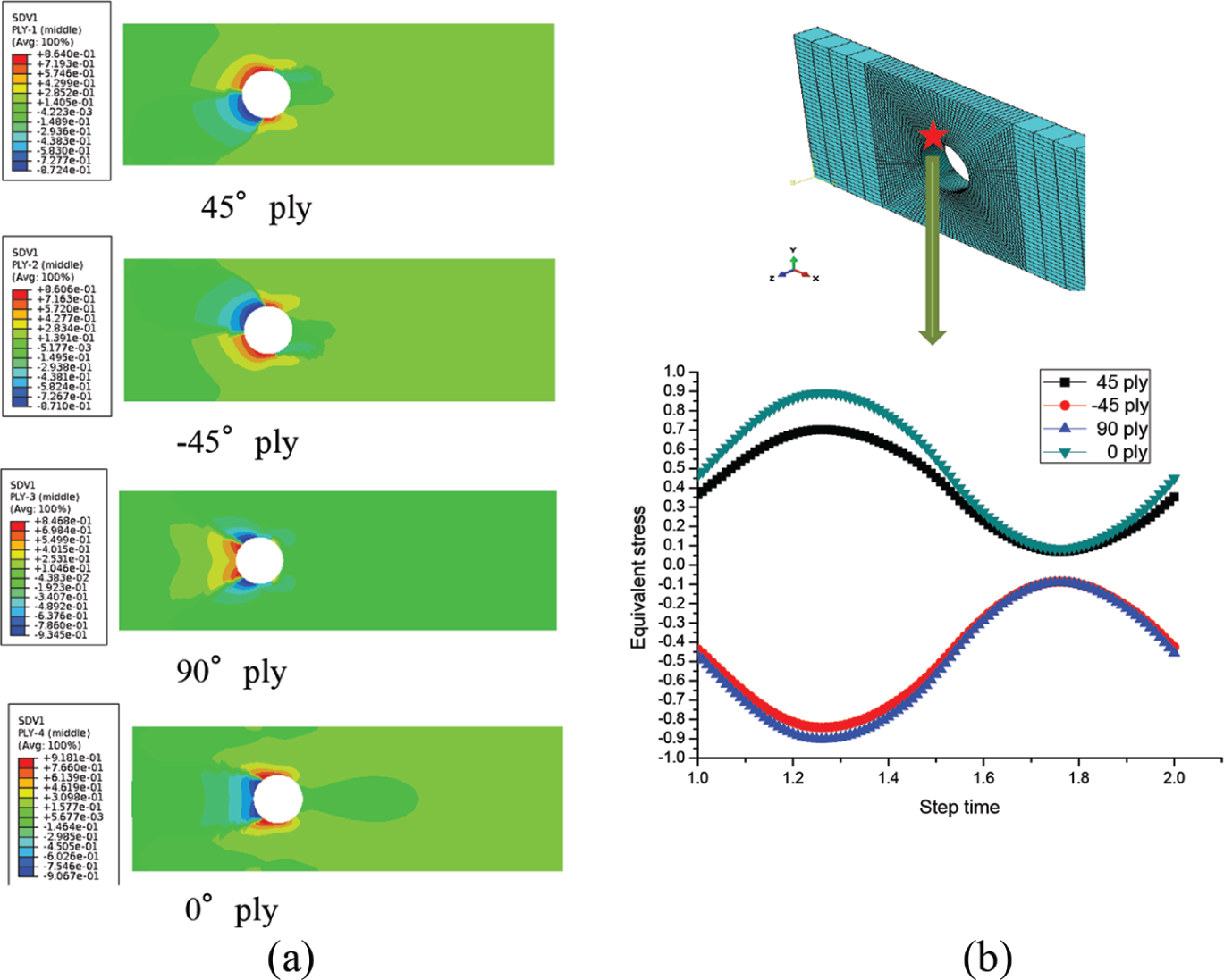
(a) Equivalent stress distribution of composite laminate and (b) equivalent stress distribution in one cycle loading.
To predict the fatigue life of composite bolted joint, stress ratio and equivalent stress of each cycle need to be calculated because stress needs to be recalculated after the element failure. As is known, stress ratio is valley stress

Calculation process of finite element model.
Progressive fatigue damage subroutine
Although equivalent stress is commonly used to predict multiaxial fatigue life, it is used less for realizing progressive fatigue damage and failure of composite bolted joints in FE method.
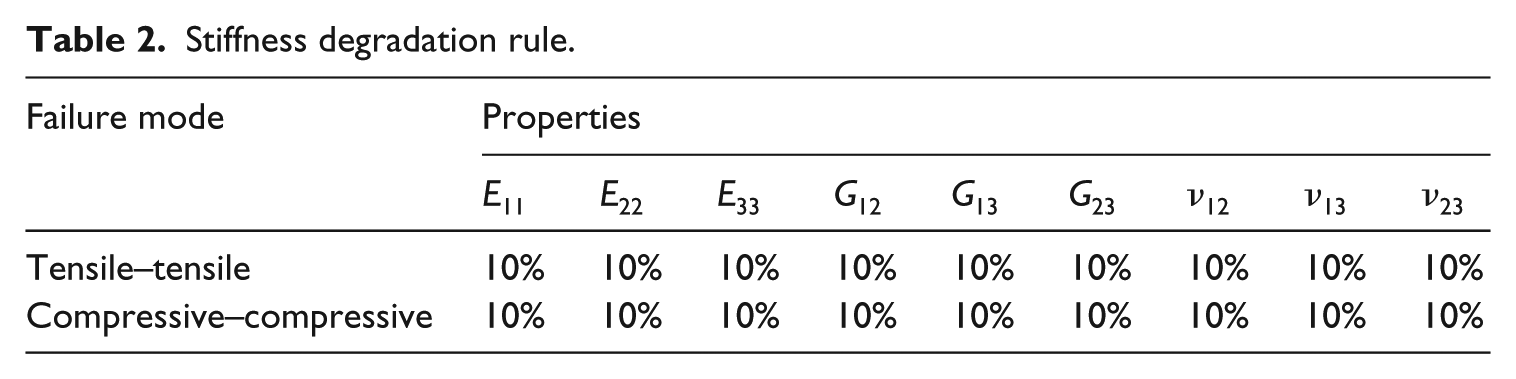
Equivalent stress, equivalent stress ratio, fatigue life and failure mode are carried out in our fatigue subroutine USDFLD. Equivalent stress is calculated according to equation (1), and equivalent stress ratio has been explained in section “Calculation process”. Then, failure mode and fatigue life will be illustrated in detail in this section. As mentioned previously, when composite bolted joint is under tensile–tensile cycle loading, different parts of laminate have significant different stress distribution. But, the main stress state of element model can be divided into two parts: tensile–tensile and compressive–compressive load condition. According to this theory, fatigue failure mode of composite bolted joint can be classified as two parts as well: tensile–tensile and compressive–compressive failure modes, as shown in Table 2. Stiffness will degrade according to Table 2 when fatigue cumulative damage
Stiffness degradation rule.
Fatigue progressive damage subroutine is shown in Figure 6. To evaluate fatigue life, equivalent stress is first used to determine whether the element fails or not. If the equivalent stress is bigger than 1, then the element fails. If field variable changes from 0 to 1, stiffness of element degrades according to Table 2. If the equivalent stress is less than 1, then fatigue damage variable (state variable in ABAQUS) is used to save the damage in the current cycle loading. It is also known that fatigue damage is calculated by S–N curve which can be founded in Campos et al.
27
In the next cycle loading, damage will be added by damage in last step until damage variable is bigger than 1. The accumulated damage is calculated by Palmgren–Miner rule. To accelerate calculation process, when maximum stresses

Flowcharts of fatigue progressive subroutine.
Results and discussion
Figure 7 shows the simulation result of composite bolted joint with geometric parameters: E/D = 3 and W/D = 3, and the maximum stresses

Comparison between simulation and experimental results of failure mode: (a) compressive–compressive failure of 0° ply and (b) tensile–tensile failure.
As shown in Figure 8, fatigue life comparison between simulation and experimental results of composite bolted joint under cycle loading with maximum stresses

Comparison between simulation and experimental results of failure life.
Conclusion
The main purpose here is to verify the validity of this progressive fatigue model and the feasibility of the FE method and establish an effective engineering fatigue life assessment model for composite bolted joints.
In this article, the fatigue model is programmed by ABAQUS USDFLD subroutine to explore fatigue life and damage of composite bolted joints with 3D Tsai–Hill fatigue failure criterion, which shows a good accuracy, compared with the experimental results.
Fibre and matrix failure could be simulated in the proposed fatigue progressive failure model. In this simulation, similar to those obtained in the experiment, failure mode of laminate under fatigue loading is bearing and shear out, which are caused by compressive failure and tensile failure, respectively.
Fatigue life of composite bolted joint in simulation under cycle loading with different maximum stresses
Since fatigue experiment is quite complicated, expensive and time-consuming, the simulation results here with good accuracy showed that this method is efficient and does not waste time.
Footnotes
Declaration of conflicting interests
The author(s) declared no potential conflicts of interest with respect to the research, authorship and/or publication of this article.
Funding
The author(s) disclosed receipt of the following financial support for the research, authorship and/or publication of this article: The work is supported by the Education Department of Shaanxi province (18JK1200) and Fundamental Research Fund of Xijing University (grant no. XJ18B02).