
Abstract
The present study focuses on the analysis and design of a novel fuzzy adaptive PID control algorithm, aiming to enhance the speed control accuracy of valve-controlled hydraulic motors under load fluctuating conditions. The method of model identification was adopted to calculate the transfer function of valve-controlled hydraulic motor based on the established hydraulic technology scheme. The chassis of the valve-controlled hydraulic motor is subsequently investigated, and a model for E-grade pavement is constructed using the harmonic superposition method. Through dynamic simulation, the load fluctuation range under two common operating conditions is determined. The fuzzy adaptive PID algorithm was subsequently designed in detail, with the error and its rate of change being considered as input parameters, while the increments of the proportional coefficient, integral constant, and differential constant were regarded as output parameters. Co-simulation data indicate that, compared with the PID algorithm, the average error of the fuzzy adaptive PID algorithm can be reduced by more than 50% and the rise time is reduced by 0.04 seconds. To validate the theoretical analysis, a tracked hydraulic chassis was developed and tested. At an expected speed of 200 rev/min, the average error decreased by 1.68 rev/min, while at an expected speed of 1000 rev/min, the average error reduced by 2.68 rev/min. The designed intelligent control algorithm can effectively improve the control accuracy and stability under load fluctuating conditions.
Keywords
Introduction
The valve-controlled hydraulic system is widely used in the field of agricultural machinery and construction machinery, 1 with the advantages of high-power density, good speed regulation characteristics, low grounding pressure, strong climbing ability, and flexible steering.2,3 Among hydrostatic systems, the valve-controlled motor circuit is widely adopted as a driving scheme. 4 The external load of the drive motor is always fluctuating due to the influence of disturbance excitation, which can affect the control accuracy.5–7 In this hydraulic circuit, energy is transferred through the flow and pressure between the controlling valve and the driving motor.8,9 In the majority of cases, PID control can yield superior outcomes. Nevertheless, this control algorithm may fall short of meeting requirements in the face of fluctuating external loads.10,11 Hence, it holds immense significance to delve into the speed control methodology of the crawler hydraulic chassis motor amidst fluctuating loads.
In recent years, the research of hydraulic chassis is mainly focused on the fields of power matching of transmission system, intelligent control algorithm, efficiency optimization of hydraulic system, and so on.12–14 Wang Wei et al. 15 studied the operating speed control system of hydraulic chassis of straw granulator. The prediction model of walking speed was established based on gray theory, and PID algorithm was adopted to control the rotational speed of hydraulic motor. The experimental data show that the overshoot of actual speed is <5%. However, the influence of load fluctuation on walking speed has not been deeply considered. In an investigation into fuzzy adaptive PID algorithm, Kumar et al. 16 established 25 fuzzy controlling rules which have ability to control the speed error to be <10 rev/min. But the range of load perturbation was defined according to theoretical speculation in this study, and the control precision is not satisfactory. In order to verify the control accuracy of hydraulic synchronous valve, Chen Jing et al. 17 carried out a series of experiments. A speed synchronization system with shunt collector valve was developed, and the simulation data show that the synchronization error of rotational speed is <5.0 rev/min. However, there is a large pressure loss in the shunt collector valve, and when the load difference between the driving motors is large, the efficiency of the hydraulic system is low. A recent study by Philipp Zagar et al. 18 design an anti-interference synchronous controller of hydraulic motor of wheeled chassis in SIMULINK. The response speed of the new controller is greatly improved compared with the PID controller. Yet this theoretical study has not been proved by experiments. Victor Goman et al. 19 analyzed the control characteristics of PID algorithm, expert PID algorithm, and neural network PID algorithm. Simulation data indicate that neural network PID control has significant advantages in terms of antiload disturbances. Similarly, this result has not been verified by the experiment.
The shortcomings of previous studies will be addressed in this article. In addition, there are three innovations in this study. In the first place, the transfer function of the hydraulic system is calculated by model identification, and its correctness is verified. In this way, the calculation results are convincing. Secondly, the range of load fluctuating is obtained by dynamic simulation rather than theoretical speculation. It is helpful for improving research efficiency and computational accuracy. Thirdly, the high precision speed control is realized by using fuzzy adaptive PID intelligent algorithm, without reducing the efficiency of the hydraulic system.
In this article, an advanced speed controlling algorithm of fuzzy adaptive PID under load fluctuating conditions is studied. The remaining parts of the study are organized as follows. In the first section, the hydraulic system is designed, and its transfer function of valve-controlled hydraulic motor is constructed by the method of model identification. In the second section, the chassis with valve-controlled hydraulic motor is studied, and the E-grade pavement model is established by harmonic superposition method. The fluctuation range of the external load of the driving motor under two common operating conditions is simulated. In the third section, the fuzzy adaptive PID control algorithm with 49 fuzzy rules is designed. The effect of fuzzy adaptive PID algorithm is verified by joint simulation. In the fourth section, a verified experiment is carried out based on the developed crawler chassis. In addition, the innovative points of this study are expounded in the fifth section. Finally, the research methods and conclusions of this study are discussed and summarized in the sixth section. The detailed block diagram is displayed in Figure 1.
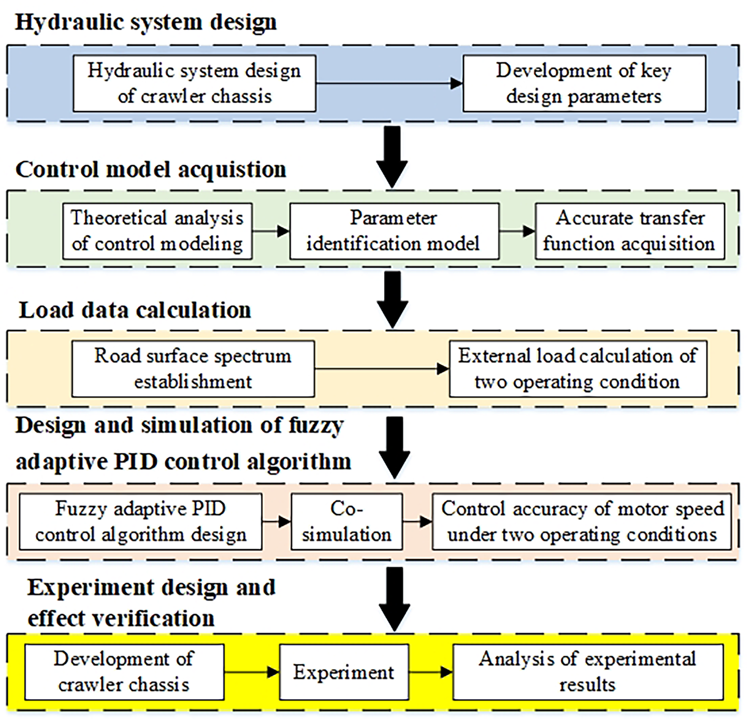
Technical flow chart.
Valve-controlled hydraulic motor system
Technical solution design
The designed hydraulic system, which is mainly composed of two gear pumps, two directional control valves, two cycloidal motors, and a controller, is presented in Figure 2. The open drive circuit is adopted in this driving system. An engine drives gear pumps 1 and 2 at the same time, and the displacement of the two gear pumps is same. Cycloidal motor can meet the output demand of crawler chassis with low speed and high output torque. The proportional direction controlling valve can not only adjust the rotation direction of the driving motors, but also change the rotation speed. The flow rate through the directional control valve can be manually or electrically controlled. This means that the travel speed of the tracked chassis can be changed in two ways. When the directional control valve is in the neutral position, the system is unloaded, and in this way, the system heat generation is effectively reduced. In addition, the tracked chassis adopts hydraulic differential steering. That is, the steering is achieved by the speed difference of the crawler driving motors on both sides. That is, when the tracked chassis is steering, the rotation speed of two cycloidal motors are different. When the two motors rotate in the opposite direction, the steering radius of the crawler chassis is minimum.

Hydraulic system principle. 1: Oil tank; 2: safety valve; 3: engine; 4: gear pump①; 5: gear pump②; 6: filter①; 7: filter②; 8: proportional directional control valve①; 9: proportional directional control valve②; 10: rubber crawler belt①; 11: cycloidal motor①; 12: rotational speed sensor①; 13: rubber crawler belt②; 14: cycloidal motor②; 15: rotational speed sensor②; 16: controller; 17: proportional amplifier①; and 18: proportional amplifier② (note: The solid black lines indicate hydraulic pipelines, and the red dotted lines indicate signal transmission paths).
The values of the key parameters are listed in Table 1.
Main designed parameters.

Control model establishment
It can be known from Figure 2 that the hydraulic motor controlled by four-way valve is adopted in the designed technical solution. Its schematic diagram is shown in Figure 3. In the process of deriving its transfer function, the following assumptions are made. Firstly, the fluid in the hydraulic system cannot be compressed. Secondly, pressure loss in the pipe is ignored. Thirdly, the pressure in the same connected area is equal everywhere. Fourthly, the volumetric elastic modulus of hydraulic oil is constant.

Diagram of hydraulic motor controlled by four-way valve. 1: Directional control valve; 2: hydraulic motor; 3: external load (note: B denotes damping of external load; J the moment inertia of external load; and K the stiffness of external load).
The flow rate equation of directional control valve can be expressed as:
The flow continuity equation is

The torque balance equation of hydraulic motor can be expressed as
Formula (5) can be obtained by Laplace transformation of formula (4).
Formulae (2), (3), (4), and (5) are combined and solved. Spool displacement and load torque are taken as input parameters and rotational angle of hydraulic motor is taken as output parameter. The transfer function can be expressed as


The standard form of the transfer function from the motor rotation angle to the displacement of the directional control valve spool can be expressed as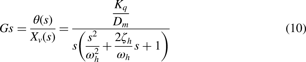

Parameter identification model in AMESim.
In this process, the working pressure of the hydraulic motor, the displacement of the hydraulic valve core, and the speed of hydraulic motor are considered as independent variables. The speed of the hydraulic motor is designated as an observed state variable. The output of the PID controller is defined as the manipulated variable. Subsequently, the Jacobian matrix of the hydraulic system can be solved in the nonlinear simulation.
Then the model identification program which can effectively extract the information of the Jacobian matrix was written, and the standard form of the transfer function from the motor rotation angle to the displacement of the directional control valve spool is shown in formula (11).
The transfer function (formula (11)) model was established in AMESim to verify the correctness of model identification results. Figure 5 displays the simulation comparison results of the physical model and the transfer function model (Figure 6).

Verified results of model identification.

Transfer function model in AMESim.
Figure 5 shows that the step function sets the expected speed of the hydraulic motor to 500 rev/min at the initial moment. The system is in an unstable state between 0 and 3.0 seconds, but the displacement trend calculated by the physical model is basically consistent with that calculated by the transfer function. After 4.0 seconds, the system enters a stable state. The displacement error calculated by the two models is small. In summary, the transfer function obtained by model identification is correct.
Load fluctuation simulation
Road surface spectrum establishment
In this part, the chassis with valve-controlled hydraulic motor is studied. First, the road spectrum model should be obtained. Road roughness has the characteristics of random, stationary, and ergodic. The theory of stationary random process is usually employed to construct the road surface spectrum which can be described by power spectral density function. Assuming that the pavement elevation is a smooth, ergodic Gaussian process, which can be simulated by different forms of trigonometric series.
The power spectral density of pavement displacement can be expressed as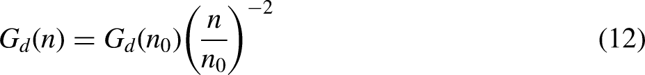
According to the characteristics of stationary random processes, the variance of pavement unevenness between spatial frequencies n1 and n2 can be expressed as

Random displacement can be obtained by superimposing sinusoidal wave functions of all intervals. According to the national standard GB7031-2005 called mechanical vibration road surface spectrum measurement data report, soft soil pavement is E-grade pavement. The crawler chassis mostly operates on soft soil surfaces. The random road surface program is compiled by using mathematical software. A displacement point is generated every 5.0 cm interval. The obtained surface roughness of E-grade road is displayed in Figure 7.
External load calculation
The model of soft soil pavement is established in dynamic simulation. And the characteristic parameters of the pavement are listed in Table 2.

Surface roughness of E-grade road.
Soft soil pavement parameters.

In this study, Baker's classical pressure–sink relationship model (formula (15)) is adopted to simulate the interaction between the crawler and the ground.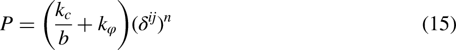
The three-dimensional model of crawler chassis was constructed, and then the model was imported into dynamic simulation. A plurality of coordinate points is formed according to the road roughness data (Figure 7). The road spectrum model can be generated according to the coordinate points. In addition, the kinematic pairs, constraints, and mechanical parameters between the individual components are accurately configured. The established dynamic simulation model is shown in Figure 8.
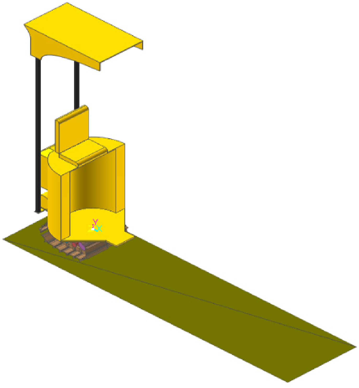
Dynamic simulation model.
The external load of the two driving motors on the left and right sides was simulated under two operating conditions. Operating condition 1 is that the crawler chassis runs in a straight line on E-grade road. In operating condition 2, at 7.5 seconds the right track crosses a 10 cm high step, while the left track always travels in a straight line on the E-grade road. The load variation curves of two hydraulic motors under two operating conditions are shown in Figure 9.
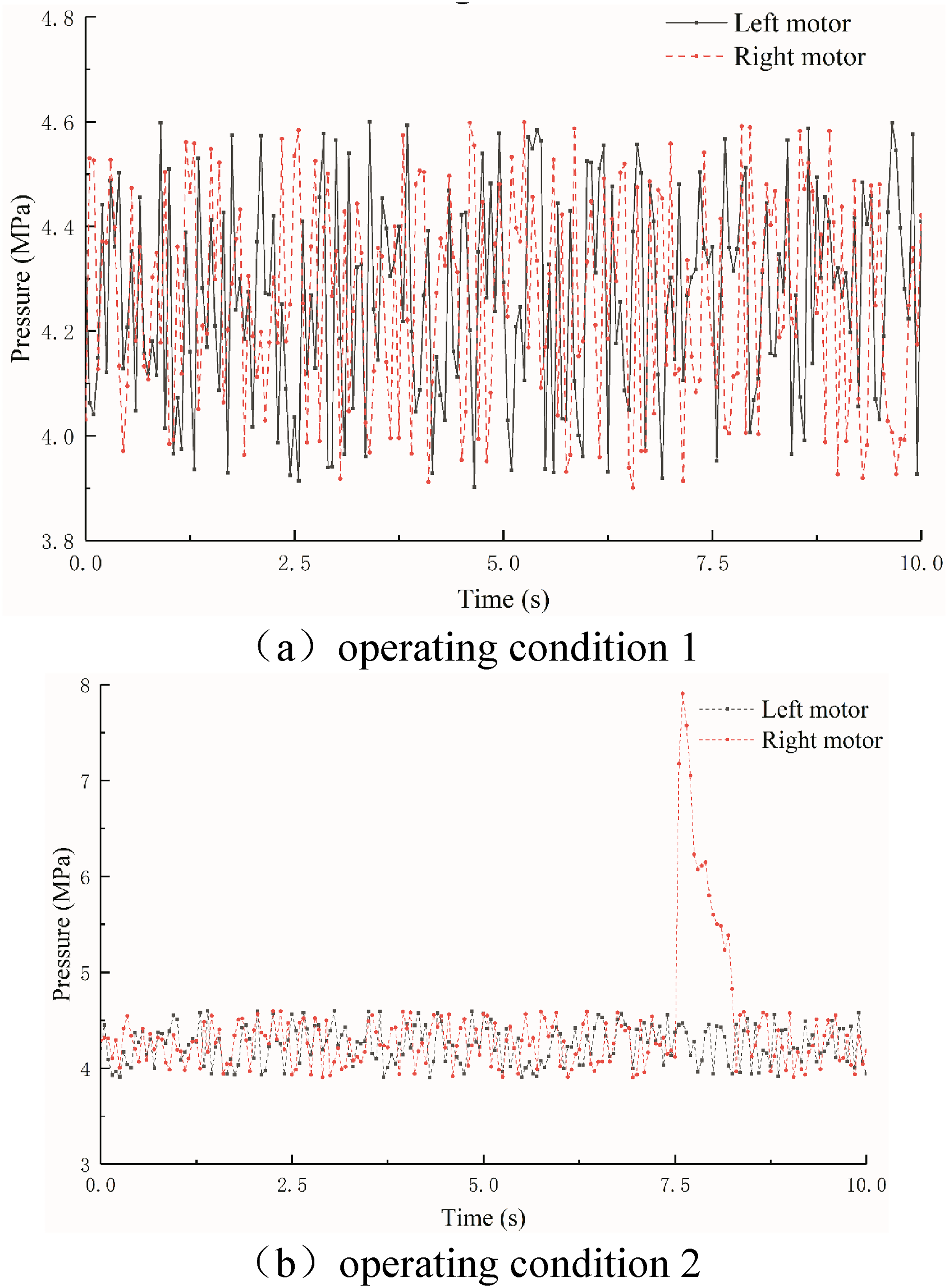
Load variation curves of two hydraulic motors.
In operating condition 1, the average value of two motor pressure is 4.272 MPa, the maximum value 4.599 MPa, and the minimum value 3.900 MPa. The operating pressure of both motors fluctuates in a small range. The maximum pressure difference between the left and the right motors is 0.671 MPa. This may have a certain impact on the stable control of motor speed. In operating condition 2, the average value of two motor pressure is 4.247 MPa. But the operating pressure on the right motor rises sharply due to the right track crossing a 10 cm high step, and the pressure reaches a maximum value of 7.906 MPa at 7.60 seconds. At this moment, the maximum pressure difference between the left and the right motors is 3.438 MPa. The larger load impact will seriously affect the speed stability of the motor. During 7.50 to 7.75 seconds, the average pressure difference between the left and the right motors is 2.723 MPa, which is likely to affect the driving straightness of the chassis.
Fuzzy adaptive PID control algorithm
Control algorithm design
The fuzzy adaptive PID algorithm consists of a fuzzy controller and a PID controller. The fuzzy controller takes error and error change rate as input parameters, and utilizes fuzzy rules to dynamically adjust the proportional, integral, and differential parameters of the PID controller. The proportional coefficient plays a crucial role in enhancing the response speed, minimizing errors, and refining the regulation accuracy of the system. A higher proportional coefficient leads to swifter response speed and improved regulation accuracy; however, it may result in overshoot and potential instability. The integral coefficient is responsible for eradicating steady-state error within the system. An excessively large integral coefficient can lead to integral saturation during the initial response phase, causing greater overshoot. The derivative coefficient contributes to enhancing dynamic characteristics of the system and suppressing deviations during the response process. If the derivative coefficient is overly large, it may prematurely slow down the response process, thereby prolonging regulation time and reducing resistance to interference within the system. Consequently, when tuning PID parameters, careful consideration must be given to each parameter's function at different stages as well as their interconnected relationships.
The principle of the fuzzy adaptive PID algorithm is shown in Figure 10. The membership functions for the proportional, integral, and derivative coefficients are depicted in Figure 11. The allowable range for the proportional, integral, and derivative coefficients spans from −6 to 6. The trigonometric membership function is employed, and seven levels of fuzzification are defined: NB (negative big), NM (negative medium), NS (negative small), ZO (zero), PS (positive small), PM (positive medium), and PB (positive big).
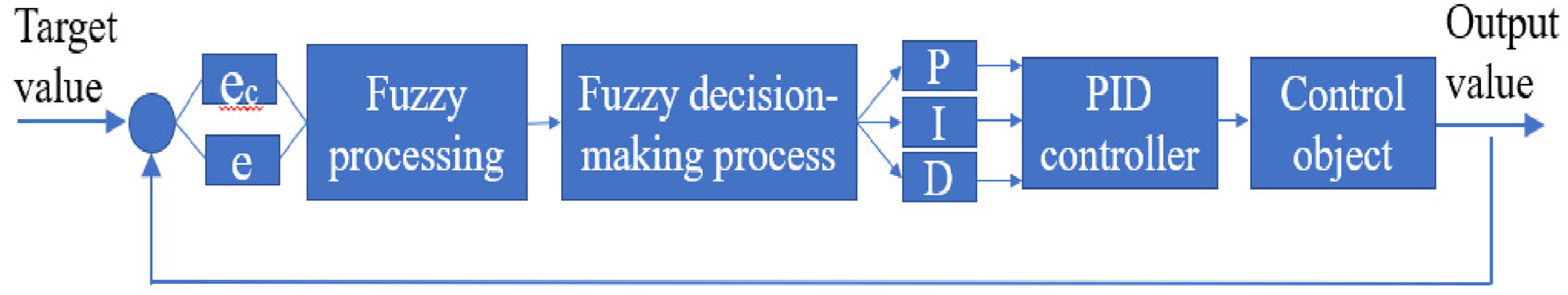
He principle of the fuzzy adaptive PID algorithm (e denotes error and ec the error change rate).
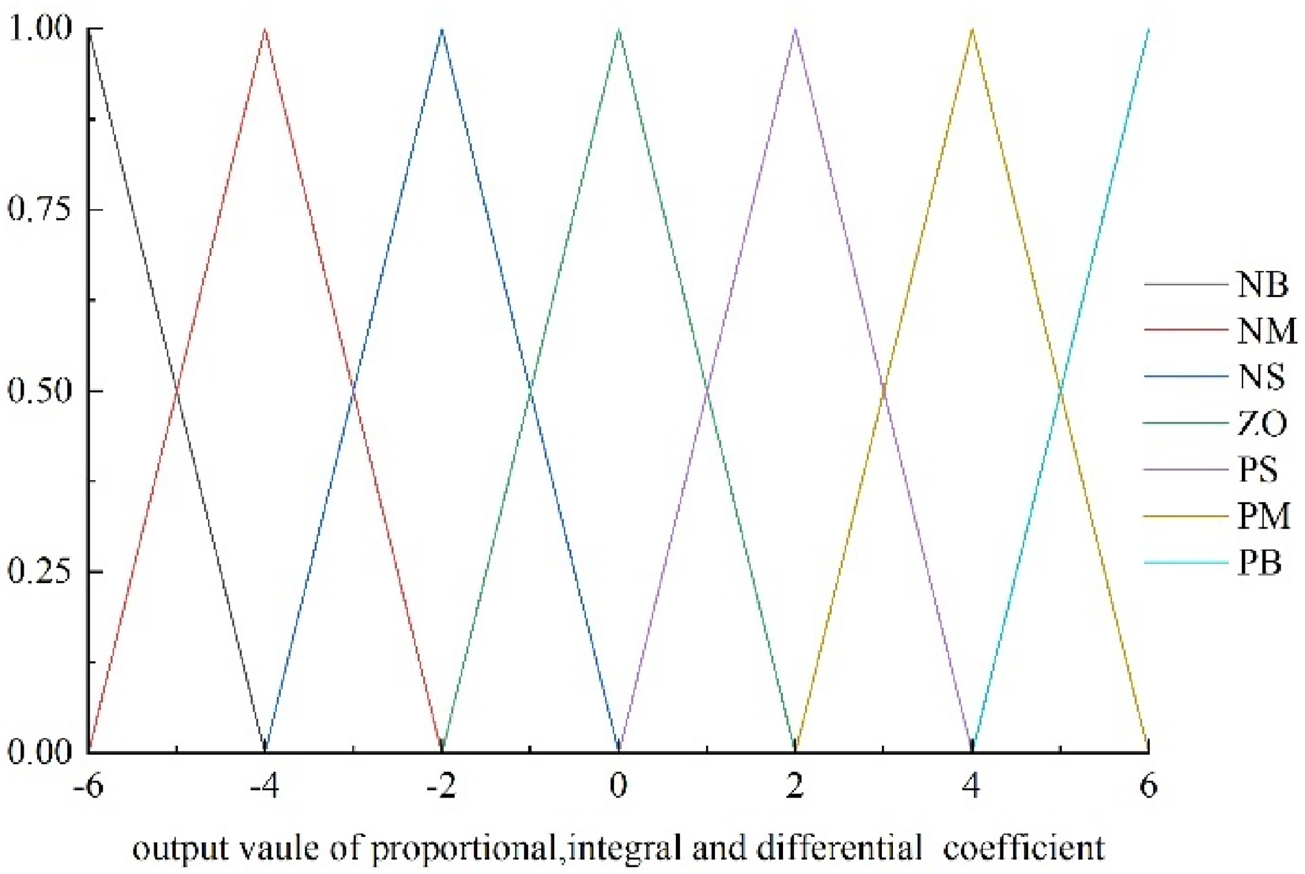
The membership functions.
The formulation of fuzzy control rules often relies on expert knowledge and an iterative optimization process. This study formulates 49 fuzzy control rules, employing trigonometric membership functions with 7 fuzzification levels. Figure 12 illustrates the control output rates of the three parameters for the fuzzy adaptive PID.
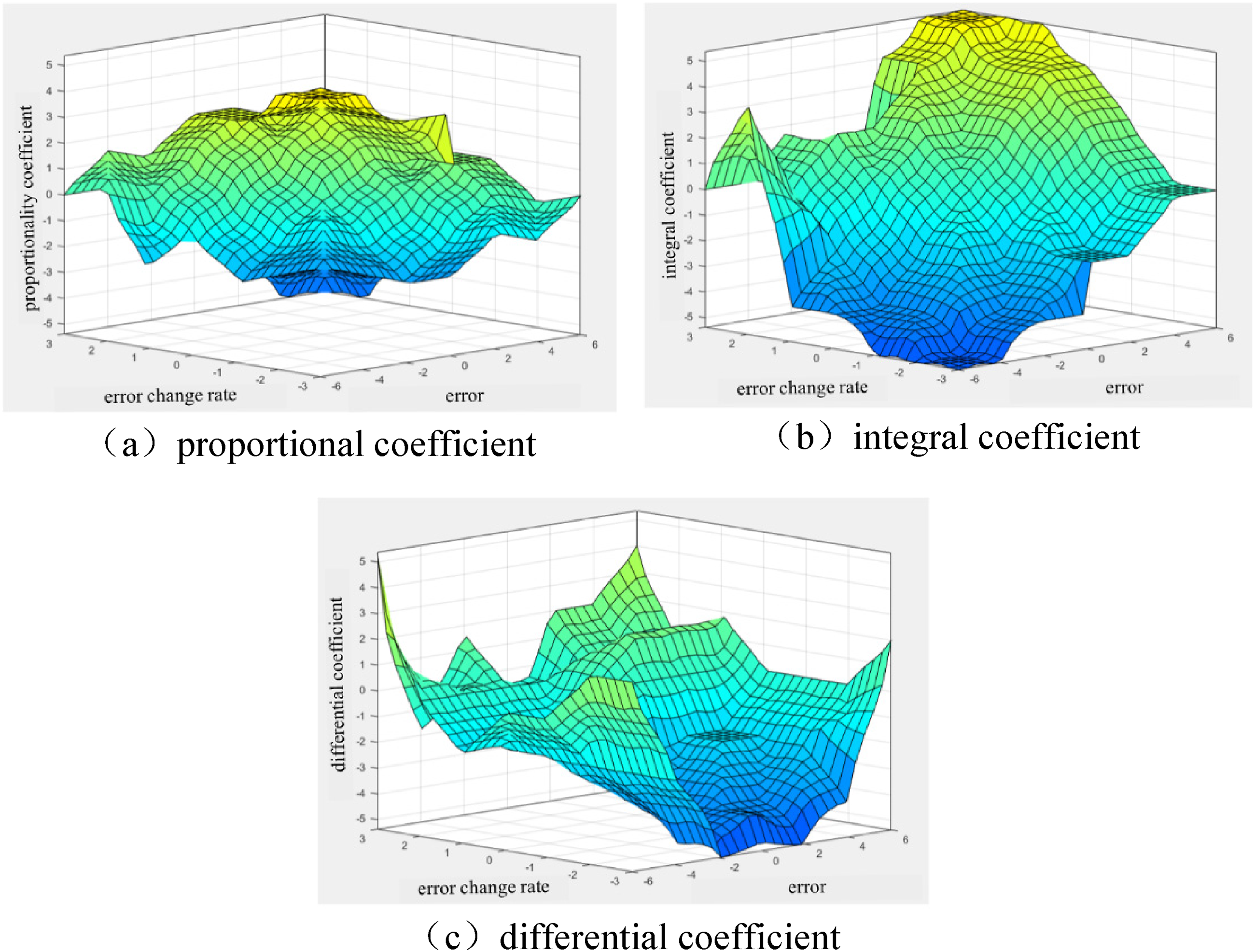
Control output rates of fuzzy adaptive PID algorithm.
Co-simulation
The joint simulation interface was established based on the hydraulic system model in AMESim, and the control algorithm model of a designed fuzzy adaptive PID (Figure 13) was also developed. In the co-simulation, it is essential to define the objective function, develop S functions, discretize variables, and devise fuzzy controllers. The data flow is bidirectional between AMESim and MATLAB, enabling real-time transmission of hydraulic system parameters to the control system, while utilizing the control output from MATLAB to regulate the state of the hydraulic system.

Control algorithm model of designed fuzzy adaptive PID.
The external load of operating condition 1 case 2 (Figure 9) was applied to the hydraulic motors as load disturbance, respectively. A sine function is set to the expected rotational speed of the hydraulic motors. The speed curves of the two hydraulic motors obtained from the simulation are presented in Figure 14. The error between the expected speed and the actual speed is shown in Figure 15. It should be noted here that it is not possible to change the motor speed rapidly according to a sinusoidal curve in the actual operation of a crawler chassis. The faster varying expected speed was set in the study to verify the control accuracy of the designed algorithm.
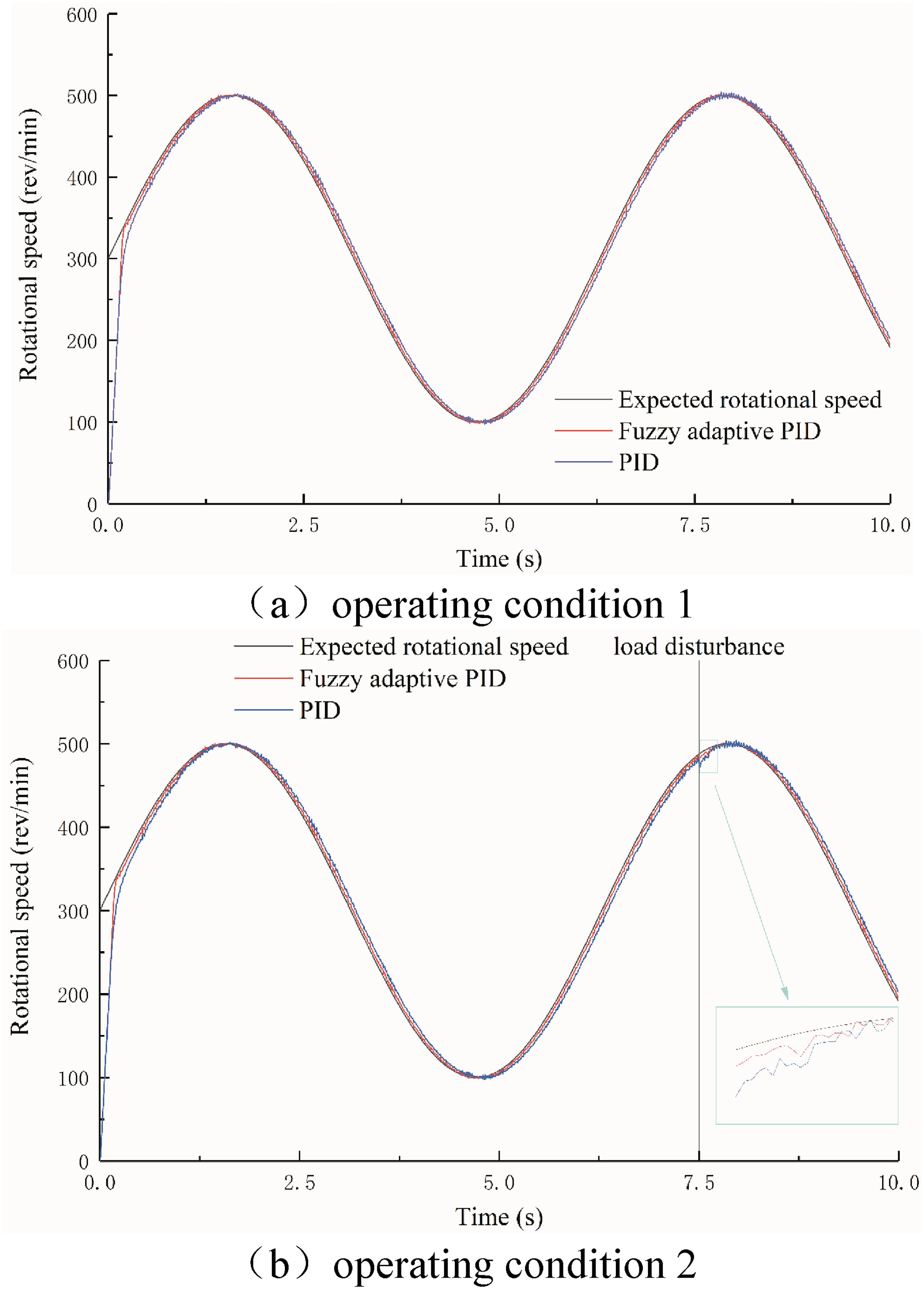
Speed variation curves of hydraulic motors under two operating conditions.
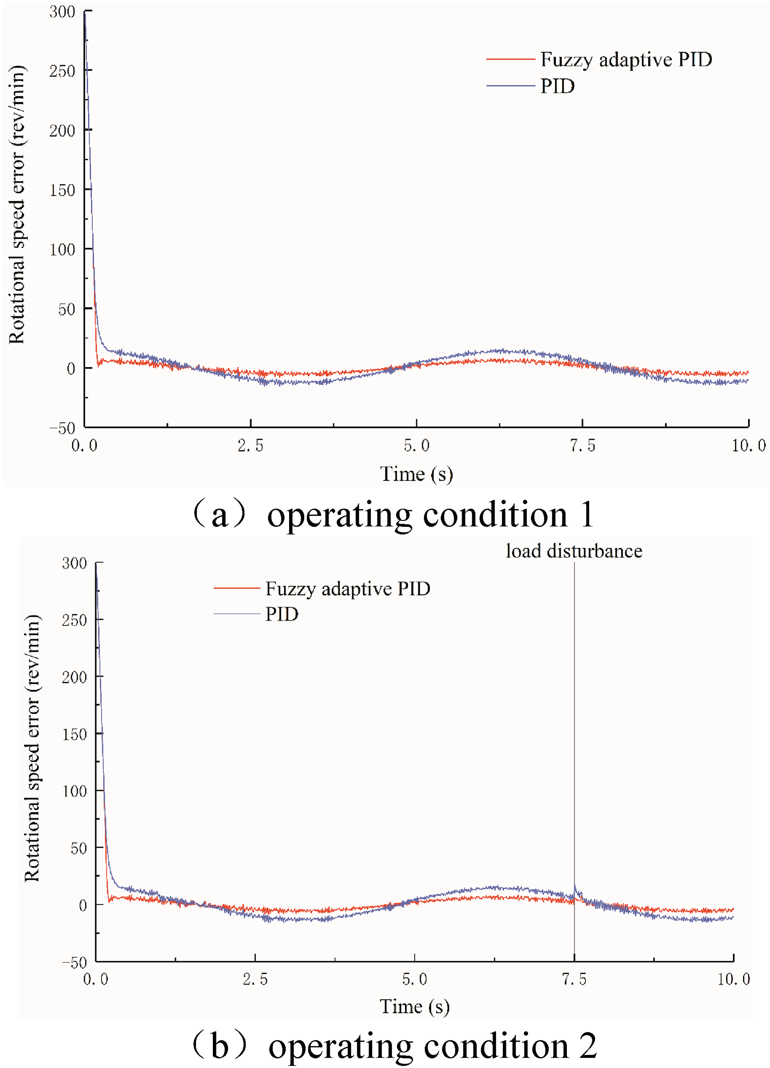
Error variation curves of hydraulic motors under two operating conditions.
The two figures are quite revealing in several ways. Firstly, the response speed of fuzzy adaptive PID algorithm is better than that of PID control algorithm under two operating conditions. The rise time is defined as the time it takes to reach 90% of the expected speed for the first time. The rise time of fuzzy adaptive PID algorithm is 0.17 seconds, but that of PID algorithm is 0.21 seconds. Secondly, for operating condition 1, the average absolute speed errors of fuzzy adaptive PID algorithm and PID algorithm are 4.73 and 9.79 rev/min, respectively. For operating condition 2, a load disturbance is applied at 7.5 seconds. In the short time that followed, the speed control error is large. During 7.5 to 7.65 seconds, the average absolute speed error of fuzzy adaptive PID algorithm is 5.61 rev/min and the maximum speed error is 7.25 rev/min. However, the average absolute speed error of the PID algorithm is 11.85 rev/min and the maximum speed error is 17.22 rev/min. These findings suggest that the response speed and controlling accuracy of the fuzzy adaptive PID algorithm are effectively improved compared with the PID algorithm.
Experiment verification
The designed hydraulic crawler chassis (Figure 16) was developed to verify the correctness of the above theoretical analysis. The parameters of hydraulic components are consistent with theoretical calculation results. Throughout the experiment, the load exhibited fluctuations upon contact between the road surface and the track. This phenomenon can be interpreted as an external load disturbance. The results of the dynamic simulation serve to validate the validity of this perspective. Two encoders are mounted on the driving motor to obtain the rotational speed in real time. The target speeds are set to be 200 and 1000 rev/min, respectively. The experimental data are shown in Figure 17.

Hydraulic clawer chassis.

Experimental data.
When the expected speed is 200 rev/min, the average speed error of fuzzy adaptive PID algorithm is 1.74 rev/min, the maximum error 4.68 rev/min, and the standard deviation 1.06 rev/min. The average speed error of the PID algorithm is 3.42 rev/min, the maximum error 9.45 rev/min, and the standard deviation 2.41 rev/min. When the expected speed is 1000 rev/min, the average speed error of the fuzzy adaptive PID algorithm is 2.05 rev/min, the maximum error 6.03 rev/min, and the standard deviation 1.34 rev/min. The average speed error of PID algorithm is 4.73 rev/min, the maximum error 9.99 rev/min, and the standard deviation 2.72 rev/min. No matter the hydraulic motor is operating at high speed or low speed, the fuzzy adaptive PID algorithm provides better control accuracy under load fluctuation condition.
Discussions
There are three innovations in this study. Firstly, we derived the transfer function by means of model identification, and the correctness was verified by comparing the speed curves calculated by the physical model and the transfer function. In Chen et al.’s study, 6 the transfer function was constructed by mathematical derivation. The results are likely to be inaccurate because some of the parameters are difficult to obtain. Secondly, it can effectively improve the research efficiency and calculation accuracy to obtain load fluctuation range of two common operating conditions by dynamic simulation. In Wang et al.’s study, 15 the authors define the load perturbation according to their own speculation. What's more, the effect of load disturbance on control accuracy was not considered in Li et al.’s study. 14 The robustness of the control algorithm could not be verified. Thirdly, compared with the method of hydraulic synchronizer, it can increase the efficiency to control rotational speed of hydraulic motor by fuzzy adaptive PID algorithm. In Kumar et al.’s study, 16 the authors controlled the rotational speed of hydraulic motors by means of a synchronization valve. The average speed error when the chassis is traveling in a straight line on E-grade road is 2.11 rev/min. Although the control accuracy is high, it also has a large pressure loss. The fuzzy adaptive PID algorithm designed in this study can balance control accuracy and transmission efficiency.
Conclusions
In this article, the advanced speed control method of hydraulic motors under load fluctuation condition is studied. The main findings are described in detail as follows. Firstly, for hydraulic motor controlled by four ways valve, the transfer function from spool displacement to hydraulic motor rotation angle is third-order if load stiffness is ignored. Secondly, the operating pressure of driving motor fluctuates between 3.900 and 4.599 MPa when the tracked chassis is driven in a straight line on E-grade road. When the one-sided track of the chassis crosses a 10 cm high step, the maximum pressure difference between the two motors is 3.438 MPa. This means that there is a load shock on the driving motor when the crawler chassis is operating on E-grade road. Thirdly, the designed controlling algorithm of fuzzy adaptive PID can effectively improve the control accuracy of motor rotational speed under load fluctuation condition. Compared with PID controlling algorithm, when the expected speed is 200 rev/min, the average error is reduced by 1.68 rev/min and the maximum error is reduced by 4.77 rev/min. Similarly, when the expected speed is 1000 rev/min, the average error is reduced by 2.68 rev/min and the maximum error is reduced by 3.96 rev/min. These results suggest that the research methods and conclusions of this article can provide reference for the speed stability control of valve-controlled hydraulic motor.
Supplemental Material
sj-docx-1-sci-10.1177_00368504241296299 - Supplemental material for Precise control algorithm of rotational speed of the valve-controlled hydraulic motor under load fluctuating conditions
Supplemental material, sj-docx-1-sci-10.1177_00368504241296299 for Precise control algorithm of rotational speed of the valve-controlled hydraulic motor under load fluctuating conditions by Kai Hu and Wenyi Zhang in Science Progress
Footnotes
Authors’ contribution
KH has contributed to drafting the manuscript, acquisition, analysis, simulation, and interpretation of the data. WZ has made substantial contributions to conducting experiment, data analysis, modification, especially improving the fluency, and accuracy of language. All authors read and approved the final version of the manuscript.
Declaration of conflicting interests
The authors declared no potential conflicts of interest with respect to the research, authorship, and/or publication of this article.
Funding
The authors disclosed receipt of the following financial support for the research, authorship, and/or publication of this article: This work has been supported by the Basic Research Project of Nanjing Research Institute of Agricultural Mechanization of the CAAS (Grant no. S202401). And partly supported by the National Key Research and Development Program of China (2021YFD2000401), the Primary Research & Development Plan of Jiangsu Province (Grant no. BE2021308) and Innovation Program of Chinese Academy of Agricultural Sciences.
Supplemental material
Supplemental material for this article is available online.
References
Supplementary Material
Please find the following supplemental material available below.
For Open Access articles published under a Creative Commons License, all supplemental material carries the same license as the article it is associated with.
For non-Open Access articles published, all supplemental material carries a non-exclusive license, and permission requests for re-use of supplemental material or any part of supplemental material shall be sent directly to the copyright owner as specified in the copyright notice associated with the article.