
Abstract
Tesla valves are widely used in the field of fluid control. To study the hydraulic performance of straight-through Tesla valves in forward and reverse flow, 16 straight-through Tesla valves with diverse blade parameters were designed in this paper, and hydraulic loss tests were carried out in forward and reverse flow under different working conditions. The results show that the hydraulic loss increases with the increasing working flow rate in forward and reverse flow; at the identical flow rate, the reverse loss is higher than the forward loss. Both the hydraulic loss through the valve and the unidirectional conductivity of the valve increase with increasing blade length, pitch, and number of blades, but too long of a length results in weakened unidirectional conductivity. The hydraulic loss increases with the increase of blade angle, and the unidirectional conductivity decreases with the increase of blade angle. When the blades are arranged in perfect symmetry, the hydraulic loss through the valve is maximum, and the valve has the best unidirectional conductivity.
Introduction
Tesla valves are passive valves that do not contain any moving parts and can achieve different flow performances in different directions. Traditional Tesla valves contain an arc channel and a straight channel, and the design of this structure makes forward flow easier than reverse flow to realize the purpose of flow control. For the new straight-through Tesla valves, there is only one channel. However, the internally distributed fixed blades act as arc and straight channel structures, enabling flow control even in single-channel pipelines. In addition, the geometric parameters of the blades can be modified to achieve different control effects.
At present, several scholars have studied various aspects of Tesla valves through numerical simulations and experiments. Menon et al. explored the influence of surface heating on the fluid flow characteristics inside Tesla valves. They found that surface heating would increase the diodicity of vertically mounted Tesla valves. 1 Du et al. proposed a photovoltaic/thermal (PV/T) system with Tesla valves to improve the energy conversion efficiency, and found that the PV/T system with Tesla valves has better heat dissipation and higher energy storage efficiency. 2 Hu et al. investigated the influence of angle on the flow of Tesla valves. It was found that the diodicity is produced by the air bubbles in the valve, and the diodicity of the valve is more significant at angles of 70–80°. 3 Wang et al. explored the influence of guide port pitch and bending pitch on the mixing efficiency and pressure drop of the Tesla valve-type mixer to find out the optimum parameter sizes. 4 Liu et al. investigated the flow performance of Tesla valves with a symmetric structure using the finite element method and magnitude analysis. The results showed that the higher the symmetry, the better the unidirectional flow performance. 5 Raffel et al. studied the influence of flow direction and Reynolds number on the flow phenomena in Tesla valves, confirming some of the phenomena during numerical simulations. 6 Chada et al. investigated multistage Tesla valves with many different angles by optimizing the geometry to achieve a higher performance. It was found that at the same flow rate, the pressure required for reverse flow is significantly higher than that for forward flow. 7 Porwal et al. performed numerical simulations of heat transfer and fluid flow characteristics of single and multistage Tesla valves. They found that the heat transfer enhancement of reverse flow is caused by flow bifurcation, stagnation, and mixing mechanisms, and the thermal diodicity increases with the increase in the stage number. 8 Zhang et al. investigated the effect of width-to-narrow ratio of the flow channel on the flow performance of Tesla valves, and found that the difference between forward and reverse pressure drop increases with decreasing width to narrow ratio. 9 Thompson et al. explored the influence of varying the stage number, valve pitch, and Reynolds number of Tesla valves. They found that the diodeity of multistage Tesla valves increases with increasing stage number and Reynolds number and increases with decreasing valve pitch. 10 Qian et al. investigated the flow performance of Al2O3 nanofluids in single Tesla valves and analyzed the effect of change in temperature, nanoparticle volume fraction, and flow rate on the flow performance. It was found that the flow ratio occupied by the mainstream increases with the temperature, nanoparticle volume fraction, and flow rate, and the diodicity increases nearly linearly with increasing flow rate. 11 Liosis et al. simulated the flow of Fe3O4 nanofluids during forward flow through Tesla valves and investigated the particle distribution and mixing efficiency at different inlet velocities. 12 Vries et al. proposed and tested a new Tesla-type passive valve by laminar single-phase modeling and steady-state two-phase flow experiments. The valve was found to be able to promote the circulation of the pulsating heat pipe and improve its thermal resistance. 13 Wang et al. proposed a new type of near-zero wear non-contact self-impact seal based on the Tesla valve structure. They found that increasing the sealing stage number and reducing the sealing spacing can effectively control the leakage. 14 Lai et al. proposed a Tesla valve-based battery thermal management system and explored the influence of cold plate position and Tesla valve channel parameters by coupled battery cold plate simulation. They found that the side cooling has better thermal performance than the main surface cooling, and the Tesla valve-type channel has better thermal performance and cooling efficiency than the straight-type channel. 15 Zhang et al. designed a new type of multistage pressure-reducing valve based on the Tesla-type orifice valve, which can provide safer and more effective pressure reduction under complex conditions. 16 Lu et al. proposed a Tesla valve-type channel cold plate and explored the effects of the angle and distance between adjacent Tesla valves, the distance between adjacent channels, and the coolant inlet velocity on the batteries through numerical simulation. 17 Fan et al. proposed a liquid-cooled plate with multi-stage Tesla valve structure and performed a multi-objective optimization design by using a genetics algorithm to obtain more efficient cooling performance and lower pumping power consumption. 18 Liu proposed a straight-through duct check valve with inactive blades and investigated the valve by machine learning, numerical simulation, and full-scale testing. The results showed that this new check valve possesses better diodicity and checkability than the conventional Tesla valve. 19
In summary, the existing studies are based on the variation of the Tesla valve's parameters and structure, as well as the effect of the change in the fluid medium on the valve's flow performance. Some scholars have also proposed novel applications of Tesla valves in various industries based on their structure and performance and have conducted simulation and experimental studies on their applications. However, most existing studies are mainly based on traditional multi-channel Tesla valves, and the research on straight-through Tesla valves needs to be covered in depth. In this paper, 16 types of straight-through Tesla valves are designed and experimentally studied under different working conditions, through which the variation of hydraulic loss during forward and reverse flow is obtained.
Experimental bench and models
Experimental bench
Figure 1 shows the pressure drop test rig for straight-through Tesla valves. The test rig consists of a tank, power pump, 3D printed straight-through Tesla valve models, high-precision digital pressure gauges, air evacuation valves, high-precision digital flow gauge, flow regulating valve, and rubber hose. The pump is a bottom suction submersible pump with the design parameters of flow rate Qr = 5m3/h, head Hr = 5 m, and rated power 125 W. Pressure is induced from the test model, and YB-80A series digital pressure gauges are installed, with a range of 0–20 kPa, an accuracy level of 0.4, an uncertainty of ±0.2% for pressure testing, and a pressure signal response time of less than 20 ms. The instantaneous flow rate is measured by a k24 gear meter with a 1–40 L/Min range and a measurement accuracy of ±1%.
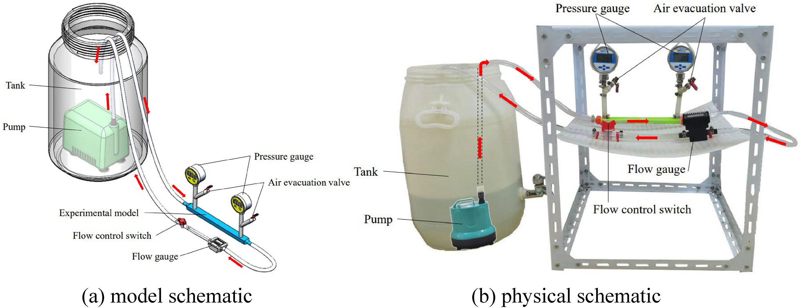
Experimental bench. (a) Model schematic and (b) physical schematic.
The pumping medium is clear water at room temperature. In the absence of air evacuation valves, when the pump starts, clean water flows into the pipe, and most of the air in the pipe is discharged. However, it was found that the air in the pressure lead section could not be eliminated entirely, resulting in a different height of the water column in the two lead sections, which affected the test accuracy. Therefore, the test device is improved by adding air evacuation valves to the pressure lead section to eliminate the tube air and reduce the test error. After the pump runs for some time, close the air evacuation valve when the air in the tube is completely excluded, and the flow in the tube reaches a stable state, after which the flow rate reaches the required test value by adjusting the valve near the outlet, obtaining the pressure locating the inlet and outlet of test models at this moment, and obtaining the pressure drop at this flow rate. Finally, the pressure drop performance tests of the test model with different structural parameters under different flow rate scenarios are completed sequentially.
Experimental models
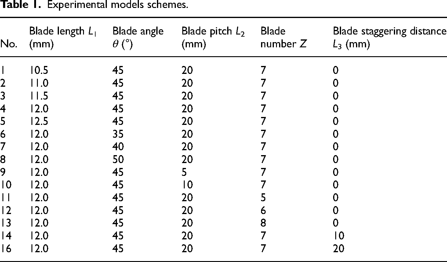
Figure 2 shows the original test model. Figure 3 shows the model structure parameter variables. In this paper, based on the original model, there are 16 test models in total obtained by changing the structural parameters of the original model, such as blade length L1, blade angle θ, blade pitch L2, blade number Z, and blade staggering distance L3. The test model scheme is shown in Table 1, where model 4 is the original model.

Original model.

Structural parameter variables.
Experimental models schemes.
Analysis of results
Figure 4 shows the fluid flow schematic in different directions. Fluid flows in the forward direction with less flow loss and less pressure drop. Although the obstruction of blades causes the flow energy loss, the direction of the tributary flow close to the blade wall and the mainstream flow direction do not show the opposite situation; the tributary does not hinder the mainstream flow too much, and the mainstream energy loss is relatively small. For reverse flow, the fluid will also form a tributary attached to the wall, but the tributary flow direction is nearly opposite to the mainstream flow direction; the tributary seriously obstructs the flow of the mainstream and forms vortices, resulting in greater energy loss.

Flow diagram inside the valve. (a) Forward and (b) reverse.
Pressure drop20,21 is the reduction in pressure caused by energy loss during the fluid flow, and it can measure the hydraulic losses in different flow directions of the Tesla valve. Figure 5 shows the pressure drop variation curves with flow rates for straight-through Tesla valves with different blade lengths. Regardless of forward and reverse flow, the pressure drop increases with flow rate at each blade length. As seen for forward flow with blade length L1 = 11.5, at flow rates of 1.8, 2.2, 2.6, 3.0, 3.4, 3.8, and 4.2 L·min−1, the corresponding pressure drop is 1926, 2547, 3286, 4364, 5780, 7410, and 9033 Pa, respectively. It is also found that the pressure drop variation under a big flow rate is much more significant than that under a small flow rate. For this blade length, the pressure drop only increases by 621 Pa when the flow rate rises from 1.8 L·min−1 to 2.2 L·min−1, while the pressure drop increases by 1623 Pa when the flow rate rises from 3.8 L·min−1 to 4.2 L·min−1.

Pressure drop variation characteristics for different blade lengths. (a) Forward and (b) reverse.
It can be found that the reverse pressure drop is greater than the forward pressure drop for straight-through Tesla valves at all blade lengths at any flow rate. As seen for reverse flow with blade length L1 = 11.5, at flow rates of 1.8, 2.2, 2.6, 3.0, 3.4, 3.8, and 4.2 L·min-1, the corresponding pressure drop is 2784, 3786, 4974, 6638, 8853, 11,426, and 14,295 Pa, respectively. At all flow rates, the pressure drop in reverse is higher than the pressure drop in forward. In addition, it was found that the difference in forward and reverse pressure drops increases as the flow rate increases. For this blade length, the corresponding forward and reverse pressure drop difference is 858, 1239, 1688, 2274, 3073, 4016, and 5262 Pa for flow rates of 1.8, 2.2, 2.6, 3.0, 3.4, 3.8, and 4.2 L·min-1, respectively. The difference in pressure drop at a small flow rate is significantly lower than at a big flow rate.
As the blade length increases, the pressure drop at each flow rate increases significantly. As seen for forward flow with a flow rate of 1.8 L·min-1, the corresponding pressure drop is 594, 1001, 1926, 4186, and 5534 Pa for blade lengths of 10.5, 11.0, 11.5, 12.0, and 12.5 mm, respectively. When the test flow rate rises to 4.2 L·min-1, the pressure drop is 3709, 4923, 9007, and 19,380 Pa for blade lengths of 10.5, 11.0, 11.5, and 12.0 mm. When the blade length is 12.5 mm, the flow rate in the straight-through Tesla valve cannot even reach the test flow rate of 4.2 L·min-1 due to the high resistance inside the valve. At other flow rates, the hydraulic loss of fluid through straight-through Tesla valves with longer blade lengths is also higher than that of straight-through Tesla valves with shorter blade lengths.
Figure 6 shows the pressure drop curves of the straight-through Tesla valve with flow rates for different blade angles. Overall, the pressure drop at each blade angle rises with increasing flow rate, and the pressure drop difference under big flow rates is higher than the pressure drop difference under small flow rates. Meanwhile, at an identical flow rate, the reverse pressure drop is greater than the forward pressure drop, and the difference between the forward and reverse pressure drop at a big flow rate is more significant than that at a small flow rate.

Pressure drop variation characteristics for different blade angles. (a) Forward and (b) reverse.
As the blade angle increases, the resistance to fluid flow through the valve is greater, so the pressure drop at each flow rate increases significantly. At the blade angle θ=50°, the resistance to the fluid is maximum, so the hydraulic losses when the fluid passes through the valve are all maximum. Moreover, due to high resistance, this valve's maximum test flow rate is only 3.0 L·min−1 for forward flow and 3.0 L·min−1 for reverse flow. In contrast, at the blade angle θ=35°, the forward pressure drop at the maximum test flow rate of 4.3 L·min−1 is only about 1852 Pa, and the reverse pressure drop is about 3307 Pa. As the blade angle increases, the unobstructed passage in the middle is narrower, resulting in a higher flow loss, so the pressure drop at large angles is greater.
Figure 7 shows the pressure drop curves of the straight-through Tesla valve with flow rates for different blade pitches. In general, the variation rule of the pressure drop curve is the same as in the first two types of cases. As the flow rate becomes greater, the pressure drop gets greater, and the pressure drop increases more obviously in the big flow rate. At the same time, the pressure drop at an identical flow rate increases significantly with increasing blade pitch. As can be seen from the test flow rate of 3.6 L·min−1, when the blade pitch is 5, 10, and 20 mm, the corresponding forward flow pressure drop is 4719, 9245, and 13,548 Pa, respectively, and the corresponding reverse flow pressure drop is 5679, 11,748, and 24,660 Pa, respectively. Clearly, as the blade pitch gets larger, the pressure drops all increase. Compared to the smaller-pitch Tesla valves, as the pitch increases, the loss region increases, resulting in higher along-travel losses. The more profound impact is that, as the pitch increases, the vortex is more likely to form between the blades, and the flow direction of the vortex convergence with the mainstream is nearly opposite to that of the mainstream, resulting in greater energy loss. When the blade pitch is small, take the blade pitch of 5 mm as an example, it is more challenging to form vortices between the blades, so the losses are smaller.

Pressure drop variation characteristics for different blade pitches. (a) Forward and (b) reverse.
Figure 8 shows the pressure drop curves of the straight-through Tesla valve with flow rates for different blade numbers, and the variation rule of pressure drop curves is the same as in the first three cases. With the more blade number, the hydraulic loss under each flow rate increases. As shown in the test flow rate of 3.6 L·min−1, when the blade number is 1, 3, 5, and 7, the corresponding forward flow pressure drop is 3259, 5246, 11,096, and 14,074 Pa, respectively, and the corresponding reverse flow pressure drop is 3421, 5518, 14,236, and 24,609 Pa, respectively. There is no doubt that as the number of obstructing blades in the valve increases, the energy loss must increase, and the pressure drop must increase. Also, for reverse flow, an increase in blade number means an increase in vortices between the blades and more reverse tributaries converging with the mainstream, resulting in more energy loss.

Pressure drop variation characteristics for different blade numbers. (a) Forward and (b) reverse.
Figure 9 shows the pressure drop curves of the straight-through Tesla valve with flow rates for different blade staggering distances. Comparing the pressure drop curves under different staggering degrees, it is found that the overall variation rule of each curve is the same as in the first four cases. It can be found that, regardless of the blade geometry parameters, the hydraulic loss in the forward and reverse flow increases with the increasing flow rate. At the same time, the hydraulic loss in reverse flow is higher than the hydraulic loss in forward flow.

Pressure drop variation characteristics for different blade staggering distances. (a) Forward and (b) reverse.
The pressure drop at the same flow rate does not increase or decrease singularly with increasing staggering distance. Taking the test flow rate of 3.6 L·min-1 as an example, when the staggering distance is 0, 10, and 20 mm, the corresponding forward flow pressure drop is 13,930, 5765, and 8412 Pa, respectively, and the corresponding reverse flow pressure drop is 24,615, 6332, and 11,629 Pa, respectively. At each flow rate, the hydraulic loss is maximum for a staggered distance of 0 mm, followed by a staggered distance of 20 mm, and minimum for a staggered distance of 10 mm. As can be seen, the hydraulic loss is greater when the blades are perfectly symmetrical. When the staggering distance is 0 mm, it is completely symmetric, and a staggering distance of 20 mm can also be regarded as a completely symmetric blade, so the hydraulic loss is greater in these two cases.
Diodicity is an essential measurement of the unidirectional flow performance of Tesla valves and is related to the magnitude of the loss of pressure potential energy in the valve during forward and reverse flow. As shown below,
The effect of each geometric parameter on the unidirectional flowability of the straight-through Tesla valve is shown in Figure 10. As can be seen in Figure 10(a), the difference in Di number at the same flow rate is small for blade lengths of 10.5 mm and 11.0 mm. With the increase in blade length, the Di number under each flow rate increases gradually and reaches the maximum value when the blade length is 12.0 mm, and the unidirectional flow performance of the straight-through Tesla valve reaches the best. However, when the blade length grows from 12.0 mm to 12.5 mm, the Di number under each flow rate decreases again, which shows that it is not the longer the blade, the better the unidirectional flow performance of the valve. Comprehensively, with the increase in blade length, the unidirectional flowability of the valve increases first and then decreases.

Effect of geometric parameters on Di. (a) Blade length, (b) blade angle, (c) blade pitches, (d) blade number, and (e) blade staggering distance.
The effect of blade angle on the unidirectional flowability of the straight-through Tesla valve is shown in Figure 10(b). Overall, the unidirectional flowability of the valve decreases with increasing blade angle. For the experimental flow rates of 2.2 L·min−1, 2.6 L·min−1, and 3.0 L·min−1, the Di value corresponding to the blade angle of 35° is 1.71, 1.88, and 2.11, respectively, and that corresponding to the blade angle of 50° is 1.11, 1.09, and 1.07, respectively, which shows a significant difference in the unidirectional flow performance of Tesla valves at the two blade angles.
The effects of blade pitch and blade number on the unidirectional flowability of the straight-through Tesla valve are shown in Figure 10(c) and (d). It can be found that the Di at all flow rates increases gradually with the increase in blade pitch and blade number. As described above, when other geometric parameters are the same, the increase of blade pitch makes the reverse flow easier to form vortices between the blades, and the increase of the number of blades also makes more vortices to form in the reverse flow, and the increased pressure potential energy loss in the reverse flow is undoubtedly greater, and thus the larger the value of Di.
The effect of blade staggering distance on the unidirectional flow of straight-through Tesla valves is shown in Figure 10(e). It is clearly seen that at all experimental flow rates, the Di values at blade staggering distance of 0 mm are higher than the Di values at blade staggering distance of 20 mm, and the Di values at blade staggering distance of 20 mm are higher than the Di values at blade staggering distance of 10 mm. It shows that the higher the blade symmetry, the better the unidirectional conduction performance of the Tesla valve.
Conclusion
The influence of five key geometric parameters on the hydraulic performance of straight-through Tesla valves is systematically investigated through experiments in this paper, which grasps the influence degree of blade length, blade angle, blade pitch, number of blades, and staggered distance of blades on the hydraulic loss of forward and reverse flow of straight-through Tesla valves as well as their unidirectional conduction performance. The results are found:
With the increase of test flow rate, the hydraulic loss in both forward and reverse directions gradually increases, and the hydraulic loss increases significantly at big flow rates. At the same time, the reverse hydraulic loss is greater than the forward hydraulic loss. As the blade length, installation angle, pitch, and blade number increase, the hydraulic loss increases in both forward and reverse flow. In the case of different staggering of the blades, the pressure drop is maximum in the case of entirely symmetrical arrangement of blades. The unidirectional conductivity of straight-through Tesla valves increases and then decreases as the blade length increases, and excessively long blade lengths result in a decrease in unidirectional conductivity. The unidirectional conductivity of straight-through Tesla valves decreases with the increase of blade angle, and increases with the increase of blade pitch and the number of blades. The unidirectional conductivity of the straight-through Tesla valve is the best under entirely symmetrical conditions.
Footnotes
Acknowledgments
The research was financially supported by the Science and Technology Project of Quzhou (Grant No. 2023K256, 2023NC08) and Zhejiang Provincial Natural Science Foundation of China (Grant No. LZY21E050001).
Author contributions
Yan-Juan Zhao analyzed experimental results. Jiang-Bo Tong carried out the experiments. Yu-Liang Zhang wrote the manuscript. Xiao-Wei Xu analyzed the results. Liang-Huai Tong proposed the innovative idea. All authors have read and agreed to the published version of the manuscript.
Data accessibility
The data that support the findings of this study are available from the corresponding author upon reasonable request.
Declaration of conflicting interests
The authors declared no potential conflicts of interest with respect to the research, authorship, and/or publication of this article.
Funding
The authors disclosed receipt of the following financial support for the research, authorship, and/or publication of this article: This work was supported by the Science and Technology Project of Quzhou, Zhejiang Provincial Natural Science Foundation of China, (grant number 2023K256, 2023NC08, LZY21E050001).