
Abstract
Water and foam have different fire-extinguishing mechanisms. Traditional foam and compressed air foam (CAF) have different bubble structures. These differences result in different thermal characteristics, which affect the extinguishing abilities during a fire. In this study, the differences in the thermal characteristics of three different extinguishing agents (water, traditional foam, and CAF) were investigated by suppressing a compartment fire. With an ignition source in the compartment (6 m × 3 m × 3 m), the agent was preferentially applied to the outside wall of the compartment. The effects of internal cooling and burnback resistance generated from the outer wall were evaluated. The performance of each agent in shielding firefighters from radiant heat while suppressing the fire inside the compartment was evaluated. When the outside wall of the compartment was covered with each of the agents, all agents were found to reduce the room temperature. When CAF was applied, the delay time until temperature re-rise was approximately 1.76–4.5 times longer than that when water was used. In addition, foaming agents exhibited a higher heat-shielding effect than water during the initial suppression. Thus, considering the thermal characteristics of these agents, fire suppression can be more effective if foam agents are used.
Introduction
Water is the most commonly used fire-extinguishing agent. In emergency fire scenarios when water is unavailable or cannot extinguish the fire, foam fire-extinguishing agents can be considered an alternative. Firefighting foam is a chemical with improved permeability because it has a lower surface tension than water. Foam is more permeable to materials such as fibers and fabrics and facilitates greater surface area contact with the fuel, resulting in faster heat absorption. 1 The foam adheres itself to the surface of the hot combustibles and extinguishes fires involving combustibles through oxygen suffocation and a cooling effect. It prevents contact between oxygen and flammable vapors and terminates the chemical chain reaction to ultimately extinguish the fire.
Firefighting vehicles equipped with a compressed air foam (CAF) system have been widely used at fire scenes. CAF contains millions of tiny bubbles created by mixing a water-foam solution with compressed air. Traditional foam systems use an air-aspirating discharge device that creates foam by aspirating and mixing air into the foaming solution 2 and are more commonly used in firefighting scenes. However, the use of CAF systems is optional. CAF is created by injecting compressed air bubbles into the foaming solution in the mixing chamber to produce complete turbulence between the gas and liquid in contrast to traditional foam systems. 3 Consequently, the mixed CAF is sprayed by the spraying device through the piping system. As the air sucked in before entering the mixing chamber returns to normal pressure after injection, the air and foam solution are evenly mixed, leading to more complete and uniform foam. 4 Therefore, CAF has a higher foam density than traditional foam. The physical properties of foam, such as its expansion ratio and bubble size distribution, 5 play a crucial role in its effectiveness. Huan Li et al. 6 found that the foam generator structure of CAFS significantly impacts foam properties and fire extinguishing performance. Specifically, under similar gas–liquid flow conditions, Kenics mixers with a larger aspect ratio produce foam with a higher expansion ratio and smaller bubble size compared to those with a smaller aspect ratio. This results in a better ability to inhibit fuel re-burning and extinguish pool fires.
Fire foam is effective in extinguishing fires by blocking oxygen through coverage of the combustible surface. The oxygen barrier of foam is a fire extinguishing mechanism, distinguishing it from water. Firefighting foam is exposed to thermal radiation. Fengyuan Tian et al. 7 found that the fuel surface temperature affected the drainage and evaporation of CAF. Perrson 8 investigated the behavior of the foam layer when it was exposed to thermal radiation and reported that thermal radiation is a crucial factor in destroying foam during the extinguishing process. The evaporation rate of foam caused by radiant heat was found to be proportional to the level of heat radiated. The foam breaks when exposed to the external heat flux, and the liquid evaporates from the foam surface. This results in the adjustment of the foam microstructure and the flow of the foaming solution. 9 Liquid evaporation of the foam causes the foam to lose its sealing and fire properties, which reduces its fire-extinguishing capability. The level of radiant heat that the foam receives affects its extinguishing capability. Foam also has a side cooling effect through moisture. Water diffuses heat through vaporization, whereas foam absorbs the heat diffused through vaporization. 10 In particular, the many bubbles in the CAF absorb more heat than an equivalent volume of water because they are surrounded by a thin water film. 11 Therefore, the thermal characteristics of the agent that determine the fire-extinguishing effect should be studied.
Agents have been extensively compared with each other in terms of their extinguishing capabilities. The extinguishing capability of CAF in a Class A fire has been evaluated and compared with that of water. In a study evaluating the extinguishing performance of CAF for wood and wood powder, which are Class A combustibles, 12 CAF demonstrated reliable extinguishing performance. The effectiveness of water and CAF in extinguishing a Class A fire was compared, 13 and the CAF cooled the temperature 75–85% faster than water with a 78% faster reduction in combustion products. The fire-extinguishing capability of CAF in a Class B fire was evaluated and compared with that of traditional foam. The ability of CAF in extinguishing oil-tanker fire was confirmed. 14 The fire combustion characteristics of CAF and the effect of each fire-extinguishing agent were studied, 15 with CAF performing better than the conventional foam system. A comparative study of CAF and traditional foam on the suppression performance of Class A and Class B fires has also been conducted.16,17 Further, in a comparative study on the suppression performance of fire-extinguishing agents in the case of compartment fires,10,18,19 the extinguishing capability of CAF was found to be superior to that of pure water and traditional foam.
The fire-extinguishing capabilities of water and foam are attributed to their thermal properties. However, most studies on firefighting agents have been verified based on the comparisons of the cooling effects of gas and heat and the extinguishing times. Studies on the thermal properties of traditional foam have previously been conducted.11,20–23 In a study on the insulation properties of foam, a test was conducted on the ignition time and foam breakage rate of static foam exposed to a certain intensity of radiation. Madrzykowski 24 studied the thermal properties of CAF by performing ignition retardation and mass retention tests. When vertical plywood was coated with CAF and radiant heat was applied to the specimen, the foam-coated plywood experienced twice the time delay to ignition than that experienced by the water-coated plywood. Increasing the foam increased the ignition retardation time. However, the study did not include a comparative test between CAF and traditional foam, thereby failing to provide an accurate evaluation of the thermal properties of CAF. Moreover, it was a small-scale experiment, thereby rendering the research results inapplicable to actual fire situations. Therefore, in this study, the cooling, burnback resistance, and radiant-heat-blocking effect of agents in the case of compartment fire suppression were investigated. The thermal characteristics of CAF, traditional foam, and water were compared.
Experimental
Experimental setup
The facility for conducting compartment fire experiments had fire-retardant expanded polystyrene sandwich panels. The length, width, and height of the structure were 6, 3, and 3 m, respectively. An opening, 0.9 m wide and 2.1 m long, was placed on the front side. Figure 1 shows the sandwich-panel compartment used in the test. The door was the only opening through which the oxygen required for a fire could flow in, and firefighters could conduct their firefighting activities from here.

Compartment of an expanded polystyrene sandwich (EPS) panel used in the experiment.
The ignition source was a gasoline pool fire. The pool was 900 mm × 900 mm and located in the lower left corner of the compartment. Combustibles were placed in the lower right corner of the compartment, such that the fire caused by the pool fire could burn and spread to the entire space. The combustibles used were wooden pallets classified as Class A fire materials according to NFPA 1403. 25 In general, polyurethane foam produces twice as much smoke as wood. 26 Rigid foams generate more smoke than flexible polyurethane foams. 27 Adam et al. 20 noted that the application of CAF does not produce vapors that can burn firefighters or reduce visibility. In the test, rigid polyurethane foam, which produces thick smoke, was added as a combustible material to evaluate the effect of heat and steam on the firefighting agents. Nine wooden pallets and 16 polyurethane foams were alternately loaded on the lower right side of the compartment, and seven wooden pallets were piled up 85 mm above the pool. Figure 2 shows the layout of the combustibles in the compartment. Table 1 lists the specifications related to the amount of combustibles used in the test.

Layout of combustibles in the compartment.
Characteristics of the combustibles used in the test.

Thermocouples and radiant heat flux
Thermocouples (TCs) were installed to record the temperature change at intervals of 1 s, for each fire-extinguishing agent. K-type TCs were used and temperatures up to 1300 °C were recorded. Figure 3(a) shows the locations of the 14 TCs installed on the outer walls of the compartment. Seven TCs were placed 1.5 m apart on the outer wall of the compartment, with each TC being installed at two heights of 1 m (B) and 2 m (T) from the floor; they were marked as OT1–OT7 and OB1–OB7. This facilitated the observation of the temperature change of the outer wall, where the agent was applied during the fire. Figure 3(b) shows the locations of the six TCs installed inside the compartment. Each of the three TCs (top, middle, and bottom) was placed at a distance of 0.85 m (1) and 1.7 m (2) from the opposite wall with the opening. Each TC was placed at a height of 1.8 m (M) from the floor and 0.5 m above and below M; the TCs were marked as IT1, IT2, IM1, IM2, IB1, and IB2. This facilitated the observation of the temperature changes inside the compartment. In particular, the start time of the fire-extinguishing process was assumed as the time when TC-IT2 reached 800 °C. In addition, to analyze the radiant-heat-blocking performance of each of the fire-extinguishing agents during fire suppression, the heat flux was measured every second at a distance of 1.2 m outside the opening.
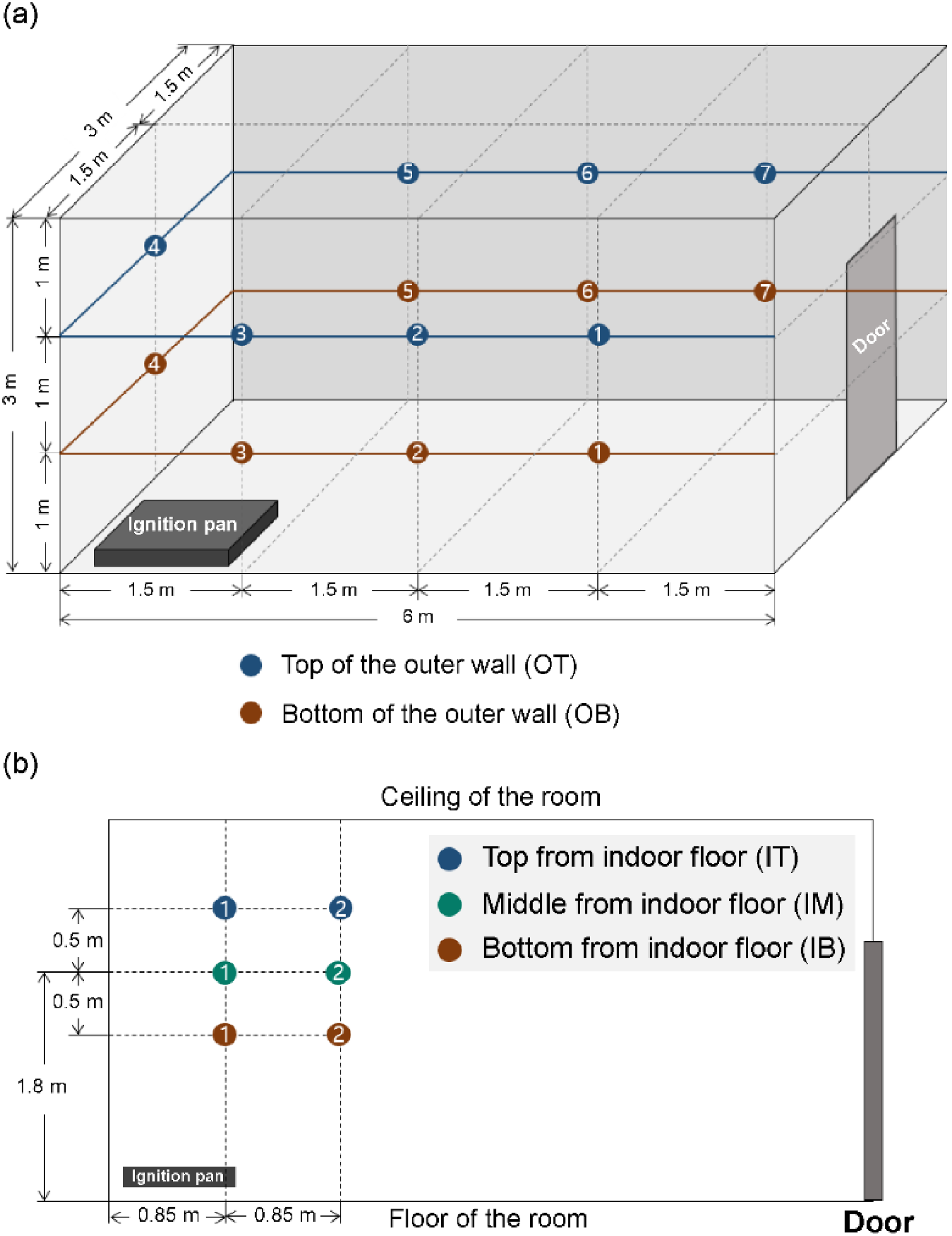
Location of TCs. (a) TCs attached to the outer wall of the compartment and (b) TCs attached in the compartment.
Fire truck with CAF system
The fire pump was a Darley model PSPBC with an output of 4000 L/min at 8.6 bar. A rotary screw type compressor with a maximum output of 4500 L/min at 8.6 bar was used. The pump's performance was 35 to 40 when the water injection distance was 80 to 100 m, and the foam injection distance was 40 mm from a pistol CAFS gun. The foam equipment was a Darley fast foam system, maintaining a foam-to-water ratio of 1.0% for Class A foam.
Experimental procedure
The fire was started at the lower left corner of the compartment via the ignition source. When the temperature in the compartment reached approximately 800 °C, the fire was considered to be at its peak, and suppression was initiated. Figure 4 shows route taken by the firefighter for the extinguishing fire. The first step was to apply the agent to the outer wall of the compartment. Firefighters performed the extinguishing process, only once, in the clockwise direction. The walls were entirely covered with the agent without overlapping. The second step was to extinguish the fire inside. Thus, suppression proceeded from the only opening in the compartment to the ignition point without the firefighters having to enter the compartment.

Route of fire suppression.
All the activities were recorded using a camera. Figure 5 presents photographs of the conducted experiments. The experiments were conducted in the order of (a) ignition, (b) fire development, (c) fire extinguishing on the outer walls, and (d) fire extinguishing inside the compartment.

Experimental procedure.
The same procedure was repeated by replacing the fire-extinguishing agent only, as depicted in Figure 5. Table 2 presents the composition of the fire-extinguishing agent used in each experiment. In test 3, the air-to-foam solution ratio was 1:9.
List of tested parameters.

In the first setup, water was used. The fire reached its peak 359 s after ignition. At this time, the internal temperature of the compartment reached 801.9 °C (TC-IT2), and 11 s later (370 s after ignition), water was applied. The firefighter jetted water to the outer wall of the compartment for 26 s and then to the interior of the compartment for 162 s. In the second setup, traditional foam was used. The fire reached its peak 258 s after ignition. At this time, the internal temperature of the compartment reached 803.5 °C, and 4 s later (262 s after ignition), traditional foam was applied. The firefighters jetted traditional foam onto the outer wall of the compartment for 29 s and then to the interior of the compartment for 157 s. In the third setup, CAF was used. The fire reached its peak at 125 s after ignition. At this time, the internal temperature of the compartment reached 806.6 °C, and 11 s later (136 s after ignition), CAF was applied. The firefighters jetted CAF onto the outer wall of the compartment for 30 s and then to the interior of the compartment for 301 s. Table 3 summarizes the extinguishment time for each setup. It was determined that most TCs inside the fire room indicated temperatures of 50 °C or lower, and no residual salt was visible to the naked eye of the firefighter.
Extinguishment time for each experimental setup.

Results and discussion
Internal cooling effect
Figure 6 shows the temperature changes indicated by the six TCs in the fire room when using water. Although water was applied to the outer walls of the compartment, the temperature increases in the compartment were delayed; however, the temperatures still tended to increase. The right graph of Figure 6 is a partial magnification of the left graph, which shows the temperature changes when water is sprayed. The average temperatures of the six TCs during water application varied from 842.78 ± 95.52 °C to 884.37 ± 67.81 °C, with a temperature increase rate of 4.93%. Therefore, the water application on the outer walls did not significantly reduce the temperature on the inside.

Internal temperature measured during water application to the outer walls of the compartment. The graph on the right is a partial magnification of the graph on the left.
Figure 7 displays the temperature indicated by the five TCs in the room on fire when using traditional foam (TC-IB2 burned out). From the time of foam application to the outer wall, the temperature rise in the compartment tended to be limited. Figure 7 shows the temperature changes when foam is applied. Two of the five TCs (IT2 and IM2) indicated decreases in temperature during foam application. The reason for the temperature decrease is assumed to be that IT2 and IB2 were located farther from the ignition point compared to IT1 and IB1. In contrast, the average temperature of the five TCs during foam application ranged from 894.28 ± 53.77 °C to 906.34 ± 62.14 °C, with the rate of temperature increase being 1.35%. This indicates that the use of traditional foam on the outer wall of the room resulted in a more effective internal cooling compared to water.

Internal temperature measured during foam application to the outer wall of the compartment. The graph on the right is a partial magnification of the graph on the left.
Figure 8 shows the temperature changes of the five TCs within the room when CAF was used (TC-IT1 burned out). When CAF was sprayed on the outer walls, the temperatures inside the compartment decreased rapidly. The tendency of the temperature to decrease was different from the two other cases where the temperature increased. Figure 8 shows the temperature changes owing to foam application. All five TCs showed similar rapid reduction in temperatures. The average temperature of the five TCs decreased rapidly from 740.84 ± 50.84 °C to 618.06 ± 45.00 °C during CAF application, and the temperature decrease rate was 16.57%.

Internal temperature measured during CAF application to the outer wall of the compartment. The right graph is a partial magnification of the graph on the left.
The rapid increase in the temperature for 120 s after ignition resulted in a lack of oxygen in the room. Therefore, even before the application of the agent to the outside, the internal temperature had begun to reduce (IT2, IM1, and IM2). However, from the time the agent was applied, all TCs exhibited the same reduction in temperature. Thus, the application of CAF accelerated the temperature decrease. Hence, the use of CAF on the outer wall affected the cooling of the inside of the room that was on fire.
Burnback resistance
Figure 9(a) and (b) shows the temperature changes of the outer wall for each agent at points OT1 and OT3, respectively. OT1, which was the farthest from the ignition point, was the least affected by the flame. OT3 was the most affected by the spreading flame owing to its proximity to the ignition point. The temperatures of the two TCs decreased because of the application of the agent, and then, the temperatures increased again. At OT1, the times required for temperature re-rise when using water, traditional foam, and CAF were 6, 25, and 27 s, respectively. The times required for temperature re-rise at OT3 was 17, 22, and 30 s for water, traditional foam, and CAF, respectively. When CAF was used, the time taken for the temperature of the outer wall to rise again was approximately 1.76–4.5 times greater than the time taken when water was used. A rapid increase in the temperature was observed when using water owing to rapid evaporation caused by radiant heat; however, traditional foam and CAF were less affected by vaporization and a longer time was required for the temperature to rise again. The temperature decrease observed in the case of CAF was attributed to the CAF having high stability and low drainage.

Temperature of the outer wall at (a) TC-OT1 and (b) TC-OT3.
Radiant-heat-shielding effects
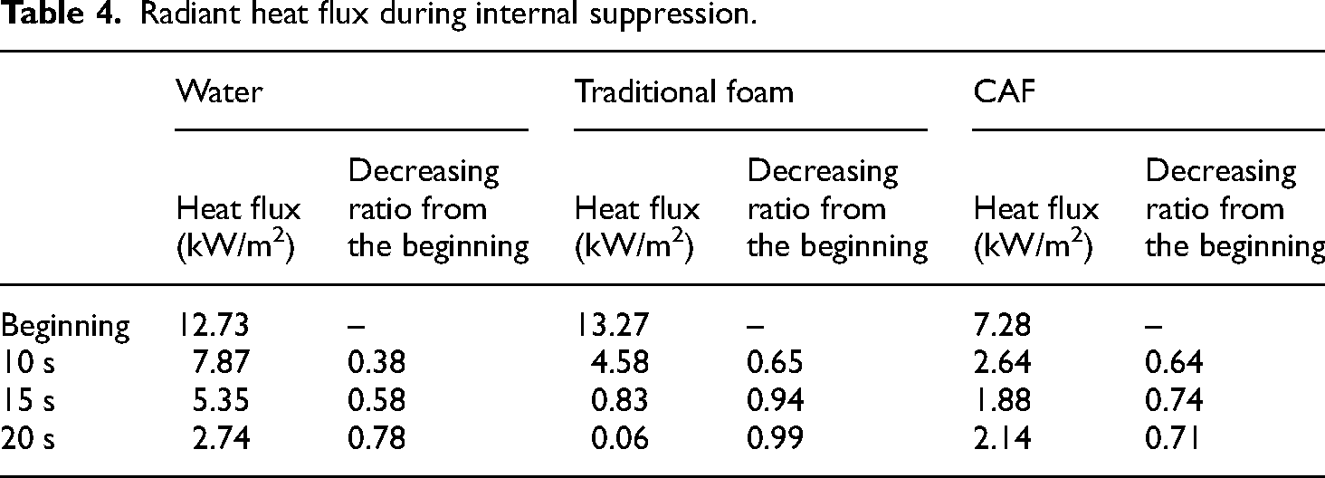
Figure 10 shows the radiant heat measured in front of the opening during the fire, and Table 4 summarizes the heat fluxes at 10, 15, and 20 s after the start of the fire suppression inside the room. After the start of suppression inside the room, a reduction in the radiant heat was observed depending on the type of the agent used. The decreasing heat flux ratio at 10 s compared with that at the start of suppression was high and it was 0.65, 0.64, and 0.38 for traditional foam, CAF, and water, respectively. The ratio when water was applied was significantly lower, indicating that the radiant heat protection provided by the foams was better than that provided by water in the first 10 s. The decreasing heat flux ratio at 15 s compared with that at the start of internal suppression was also high; it was 0.94, 0.74, and 0.58 for traditional foam, CAF, and water, respectively. The ratio of the heat flux at 15 s was greater than that at 10 s for all agents. In particular, the ratio for traditional foam increased considerably compared with that for the two other agents. The decreasing heat flux ratio at 20 s compared with that at the start of internal suppression was high; it was 0.99, 0.78, and 0.71 for traditional foam, water, and CAF, respectively. The ratio for water changed significantly, whereas that for traditional foam and CAF did not change. However, the ratio for water was still lesser than that for the foams. Thus, it can be inferred that foam protects the radiant heat more consistently than water from the beginning of ignition suppression. Therefore, when foam is applied at the beginning of fire suppression, it can protect firefighters from steam and the heat generated during suppression.

Radiant heat flux exposed during fire.
Radiant heat flux during internal suppression.
Conclusions
The thermal characteristics of CAF, traditional foam, and water were compared in the case of compartment fire suppression. When the agents were applied to the outer wall of the compartment where the fire was developing, the cooling effect on the inside was confirmed. The burnback resistance of the different agents was also compared based on the suppression of the compartment fire. The application of traditional foam to the outer wall of the compartment was found to have a better internal cooling effect than water. In addition, the delay in the temperature re-rise time with CAF was greater than that with traditional foam and water. Owing to the denser bubbles and higher heat resistance than traditional foams, CAF bubbles and their barrier effect lasted longer on the hot exterior. In addition, the foams were confirmed to be superior to water in terms of blocking the radiant heat to which the firefighters were exposed during the early stage of the internal fire suppression. However, the radiant-heat-blocking effects of CAF and traditional foam could not be clearly distinguished. In the future, a comparison of thermal characteristics is necessary to study the effect of the structural differences between CAF and traditional foam.
In this study, although the foam did not directly act upon the fire inside the room, the use of different foams on the outer wall lowered the internal temperature of the room. Thus, the thermal effect of CAF on extinguishing fires can be useful in an actual firefighting scenario.
Footnotes
Author contributions
Tae-Sun Kim: conceptualization. Tae-Hee Park: original draft preparation. Jeong-Hwa Park: visualization. Ji-Hyuen Yang: data curation. Dong-Hun Han: writing—review and Editing. Byeong-Chae Lee: validation. Jin-Suk Kwon: supervision.
Declaration of conflicting interests
The authors declared no potential conflicts of interest with respect to the research, authorship, and/or publication of this article.
Funding
The authors disclosed receipt of the following financial support for the research, authorship, and/or publication of this article: This work was supported by the Technology and Development to Support Firefighting Activities Grant (grant number 1761002660) and funded by the National Fire Agency of Korea. The funding agency had no role in the study design; collection, analysis, and interpretation of data; writing of the report; and decision to submit the article for publication.
Author biographies
Tae-Sun Kim studies firefighters' safety and response techniques. Her research interests include all aspects of firefighting equipment and fire extinguishing agents.
Tae-Hee Park is a senior researcher of National Fire Research, South Korea. He is interested in fire suppression, D-class fire, and extinguishing agents.
Jeong-Hwa Park studies the field of safety engineering. She is interested in the safety of firefighting equipment, including sprinkler equipment.
Ji-Hyun Yang has a master's degree in fire protection equipment engineering. She has interested in droplet impact phenomena on liquid pool surfaces and fire protection equipment mechanisms.
Dong-Hun Han received the PhD degree in chemistry. He has experience in analyzing fire debris and studying firefighters' safety and firefighting techniques. He is currently interested in fire prevention facilities and fire code developments.
Byeong-Chae Lee works as a firefighter in Korea. His interests include firefighting techniques and ways to ensure safety.
Jin-Suk Kwon studies firefighters' response techniques and safety in disaster situations. He is interested in fires as a whole for special phenomena such as metal fires.