
Abstract
The safety of the power transmission towers is the basis for the reliable operation of the power grid. Real-time monitoring of the strain of the key rods of the power transmission tower can reflect the safety status of the power transmission tower. In this paper, a smart rod equipped with fiber Bragg grating with strain sensitivity enhanced structure is proposed to detect the strain of key rods of large-span power transmission towers on the southeast coast of the Yangtze River. The smart rod can be connected with the power transmission tower rod through the foot nails and the force on the tower can be transformed effectively. This structure has the advantages of convenient installation and no damage to the power transmission tower. Prestress can be applied to fiber Bragg grating equipped in the smart rod through the prestressed sleeve and can be continuously and accurately adjusted, sensitivity of the fiber Bragg grating was enhanced by strain sensitivity enhanced structure. The relationship between force and strain of fiber Bragg grating installed in the smart rod was analyzed by ANSYS software. Experimental results show that the sensitivity of the fiber Bragg grating strain sensor in the smart rod is 13 times that of the conventional structure fiber Bragg grating strain sensor, and the linearity between the fiber Bragg grating wavelength change and force is as high as 0.999. Temperature compensation was realized through temperature measurement fiber Bragg grating installed in the smart rod. This structure can be used to measure the strain of a large-span power transmission tower from 0 to 2000 με with an accuracy of 0.1 με with good repeatability.
Introduction
As important equipment for overhead transmission lines, power transmission towers are extremely critical to the safe operation of power systems. Due to the considerable weight and span of the conductors, the rupture of one or multiple conductors results in significant unbalanced loads on the structure that may lead to the failure of elements and possible structural collapse of the transmission power tower. The overload due to heavy ice accumulation on conductors is another cause of failure. 1 The collapse of one or more transmission towers can cause the energy corridor to be blocked, resulting in serious consequences. 2 Thus, it is of great significance to monitor the safety status of power transmission towers. An effective way to evaluate the status of a power transmission tower is by measuring the strain state of important parts of the power transmission tower. Resistance strain gauges 3 and fiber Bragg grating (FBG) strain sensors 4 are often used to monitor the stress of power transmission towers. FBG strain sensor monitors the strain by monitoring the change of the Bragg wavelength of the grating. Compared with traditional electrical strain monitoring technology, it has the advantages of good durability, anti-electromagnetic interference, and easy multiplexing. 5
FBG strain sensors have been widely used in the health monitoring of power transmission towers, tunnels, ships, and other structures.4–12 Gu et al. 4 welded the FBG strain sensor on the power transmission tower, and holes were drilled to fix the FBG with bolts, by doing this online monitoring of the micro-stress of the high-voltage power transmission tower was realized. Liu et al. 5 installed FBG strain sensors on the cross-arm of the power transmission tower to monitor the stress changes in real-time, and analyze the relationship between the power transmission tower strain and the local climatic conditions. Xie et al. 6 from Tongji University established an ultra-high voltage power transmission tower-line dynamic characteristic model under different wind loads, and FBG was used to monitor the strain at the foot of the tower. Li et al. 7 successfully measured the surrounding rock strain based on the improved fiber grating large-range strain sensor, which is in good agreement with the surrounding geological conditions and can more accurately locate the area where large strain occurs in the surrounding rock. Mao 8 welded the FBG to the bottom of the ship by the laser welding process, which can be used to measure the strain of the key structure of the ship, and has the advantage of large range and high precision.
The above-mentioned FBG strain sensors are generally connected to the structure by means of laser welding or pasting which will cause potential damage to the structure to be measured, 10 not able to be reused and what's more, the strain transfer efficiency needs to be improved. In this article, a smart rod equipped with an FBG strain sensor with an enhanced sensitivity structure was proposed to monitor the strain of the power transmission tower. The structure can be directly connected with the foot nails on the measured rod of the power transmission tower without welding. When the power transmission tower is deformed, the strain is transmitted to the FBG strain sensor through the foot nails. The main advantages of the proposed sensor with respect to others reported in the literature are that they are easy to be disassembled and assembled because of no damage to the power transmission tower rods and can be reused without loss of sensitivity. The relationship between force and strain of FBG in the smart rod was analyzed by ANSYS software. Compared with the FBG strain sensor directly welded on the aluminum alloy sheet, the sensitivity of this smart rod increased by 13 times. The FBG sensor is packaged in the smart rod to realize temperature compensation to improve measurement accuracy.
FBG strain monitoring mechanism
FBG is a passive optical device containing a periodic refractive index modulation in the core of an optical fiber over some finite length.13–15 According to the coupled mode theory, the central wavelength


Design of smart rod with sensitivity-enhanced FBG strain sensor
The smart rod equipped with FBG strain sensing head is designed to monitor the strain state of the above-mentioned large-span power transmission tower. In engineering applications, a tube-packaged FBG strain sensor is often directly welded on the metal substrate, and the strain is transferred to the FBG by stretching the metal substrate 18 (referred to as the conventional structure in this article). But the strain transfer efficiency is relatively low with this structure. In this article, a sensitivity enhancement structure is proposed to improve the sensitivity. The main idea is to transfer strain to FBG by directly applying force to the threads at both ends of the tube-packaged FBG. Figure 1(a) is the photo of the FBG strain sensing head which FBG is bonded on an elastic beam and protected by a steel tube with threads at both ends. Figure 1(b) and (c) are the designed prestressing device and schematic diagram of strain sensitivity enhanced structure. In Figure 1(b), 401 is the FBG sensor head with external threads at both ends, and the prestressed sleeve 402 is a hollow tubular structure that is mounted along the outside of the sensor head 401. Prestress is applied to FBG by fastening nuts 403 to 402, and an FBG demodulator is used to monitor the prestress which can be continuously and accurately adjusted. In addition, an aluminum alloy casing is added to the outside of the prestressed casing by a fastening sleeve. Due to the lower elastic modulus of aluminum alloy, deformation is more likely to occur, and the deformation is transmitted to the FBG through the fastening sleeve which can further improve the sensitivity of strain measurement. The aluminum alloy sleeve can also share part of the force so as to prevent the FBG from being damaged.
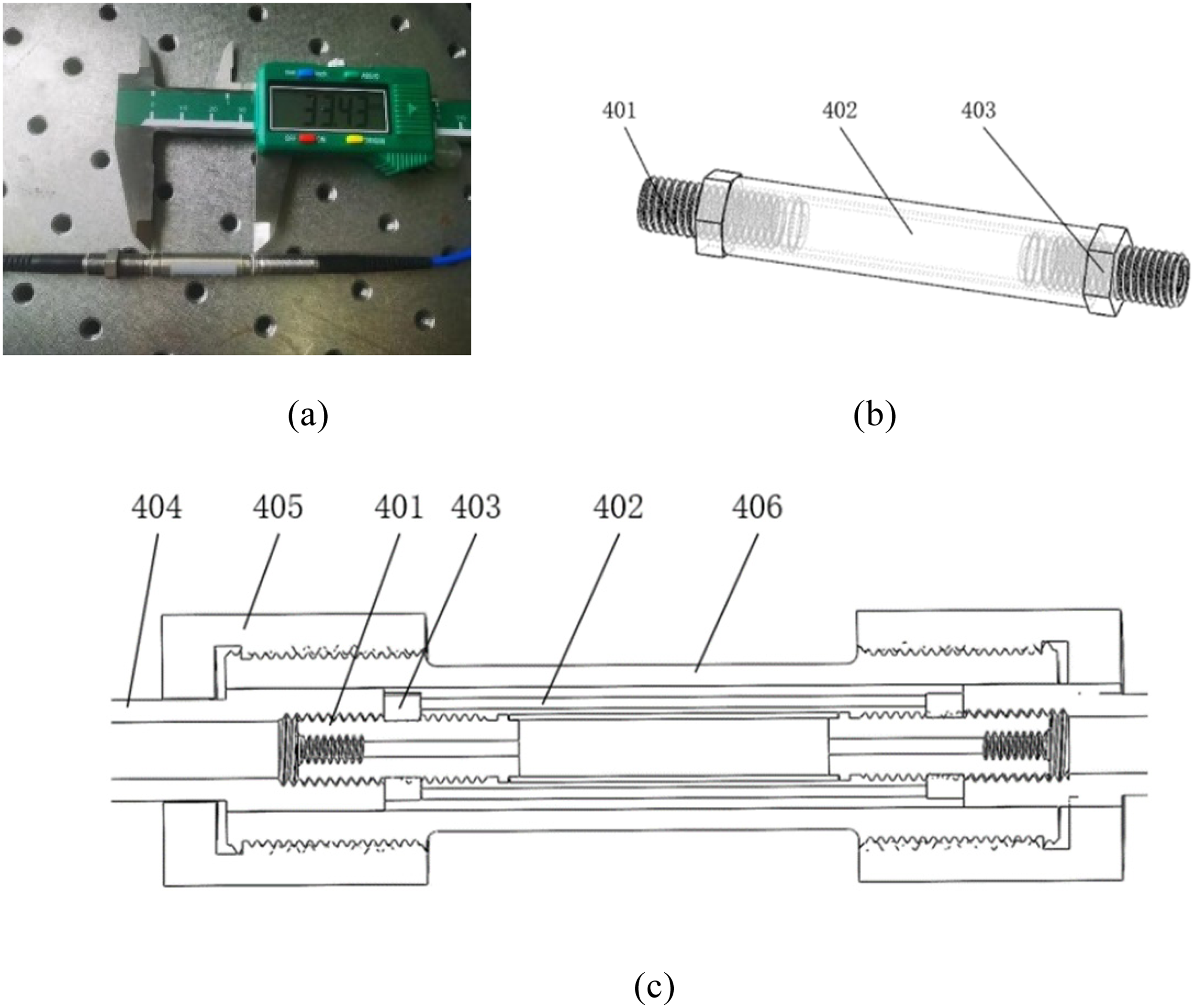
(a) Photo of fiber Bragg grating (FBG) sensor head, (b) prestressing device, and (c) schematic diagram of stress sensitivity enhanced package structure.
ANSYS software was used to model and simulate the relationship between the external force and the strain of the above-strain sensitivity-enhanced structure. Figure 2(a) shows the structure of FBG bonded on an elastic beam and the outermost aluminum alloy casing. The elastic beam in which FBG was bonded and the aluminum tube was constrained by multiple points and under external force, they will endure the same strain. Figure 2(b) shows 0.35 με was produced when 1 N of force was applied on both sides of the structure.

(a) Fiber Bragg grating (FBG) bonded on elastic beam with Al tube at the outside and (b) analysis of the relationship between force and strain with ANSYS.
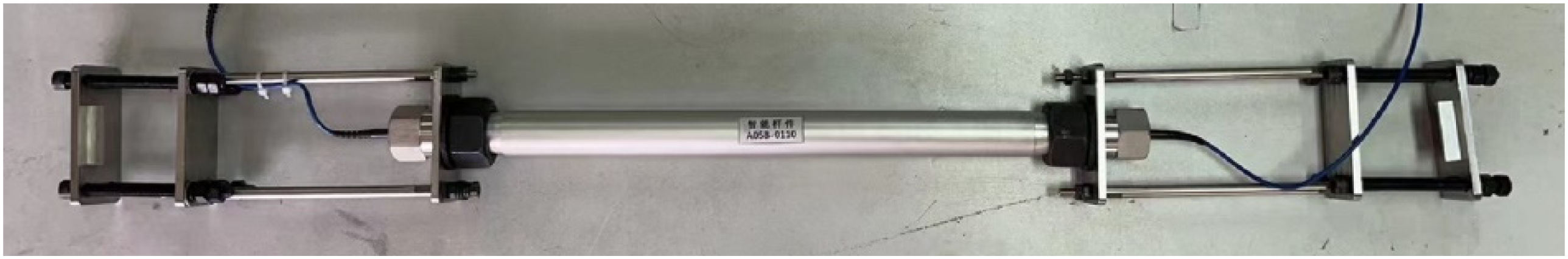
Figure 3 is a schematic diagram of the smart rod equipped with the FBG strain sensor. The smart rod is fixed on the two nails of the power transmission tower by connecting studs, fixing plates, etc. The photo of the smart rod installed at the foot nails of the power transmission tower rod is shown in Figure 4. When the power transmission tower rod is deformed under wind load, etc., the strain of the power transmission tower is transmitted to the smart rod through the foot nails, so that the Bragg wavelength of strain sensing FBG is shifted. By measuring the wavelength shift of FBG and with a precise mathematical model, the strain of the power transmission tower rod can be obtained.

Schematic diagram of the smart rod with strain sensitivity enhanced package fiber Bragg grating (FBG) sensor.
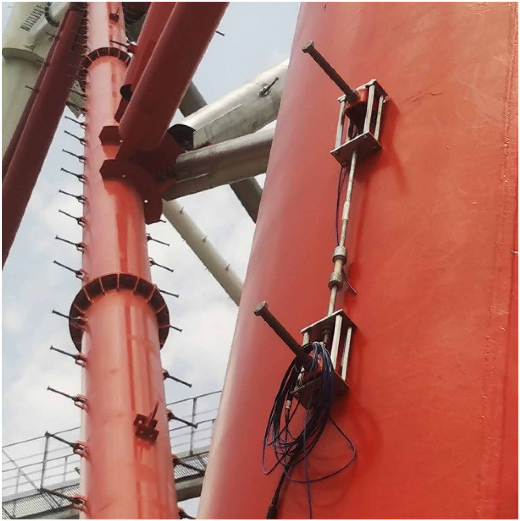
Photo of the smart rod installed at the foot nail of the power transmission tower rod.
In order to compare the performance of smart rod with strain sensitivity enhanced structure, a conventional structure FBG strain sensor was fabricated. FBG was welded on an aluminum alloy substrate with a thickness of 2 mm, and then insert the substrate into an aluminum alloy tube. The conventional structure strain sensor is shown in Figure 5.
Schematic of fiber Bragg grating (FBG) strain sensor in a conventional package.
Sensing performance of smart rod with strain sensitivity enhanced FBG
The sensing characteristics of the above two structures were measured. Figure 6 is the testing system which is mainly composed of an ASE broadband light source, a 3-dB coupler, an FBG demodulator, and a universal tension and compression machine (MTS Criterion Model 44). The clamps of MTS Criterion Model 44 were clamped at both ends of the smart rod, and tension was applied in opposite directions. The force applied to the smart rod range from 0 kg to 2000 N. For the highest force which foot nails can withstand is 2000 N, the metal part of the smart rod will be broken under 2000 N force in order to avoid destroying the foot nail of the transmission tower.
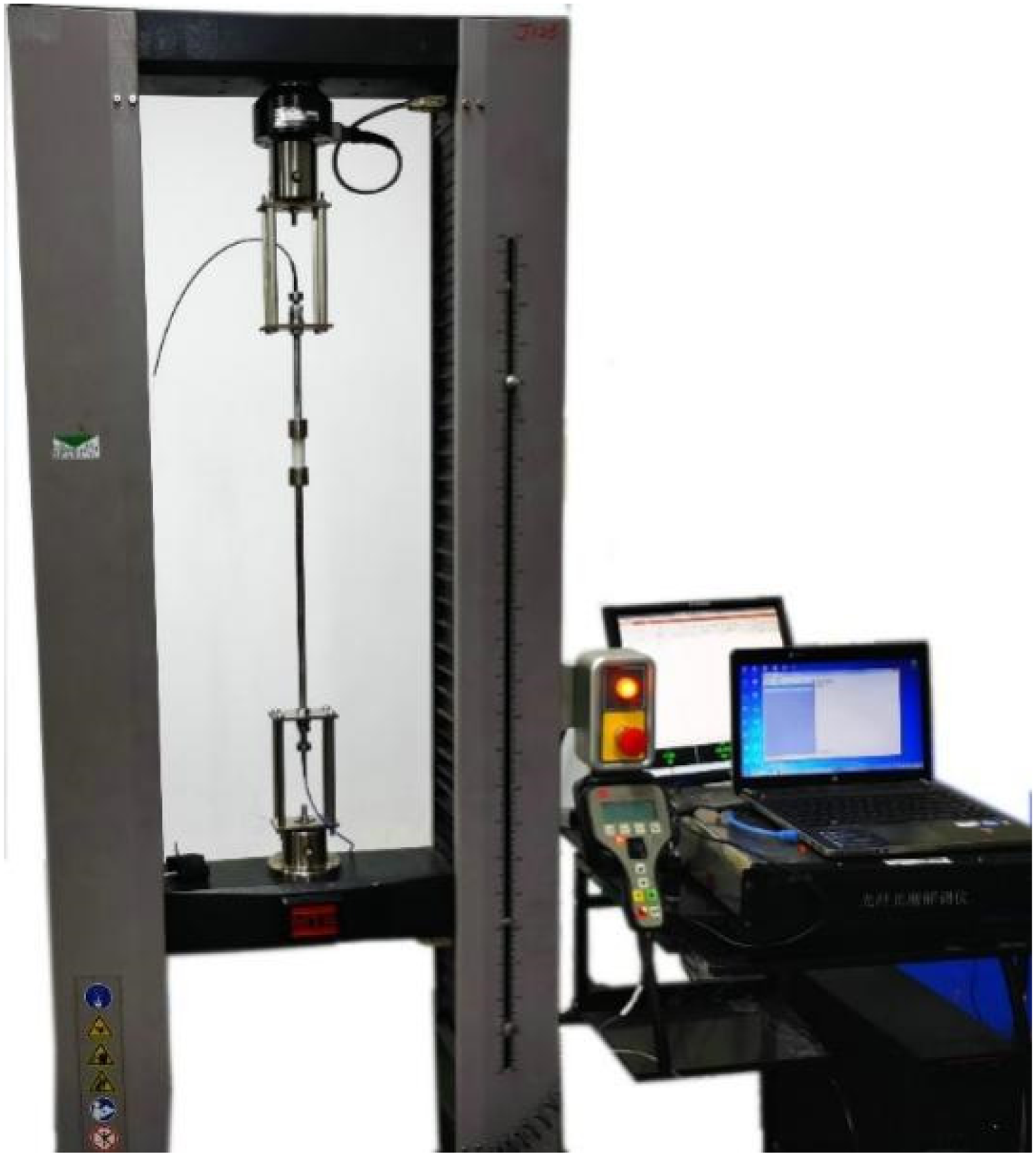
Smart rod sensing characteristic testing system.
Experiment results of the FBG strain sensor of the conventional structure and the sensitivity-enhanced structure are shown in Figure 7. The linearity between the Bragg wavelength and force of the conventional structure and sensitivity-enhanced structure is 0.9992 and 0.9999, respectively. When the applied force increased from 0 to 2000 N, the Bragg wavelength of the strain sensor with conventional structure increases from 1557.133 to 1557.31 nm which increased by 0.177 nm, and the sensitivity is about 0.0885 pm/N. Since the strain sensitivity of FBG is 1.2 pm/με, it is calculated that the strain generated by FBG in a conventional structure under 2000 N is about 148 με. The wavelength of the strain sensor with the sensitivity-enhanced structure shifted from 1557.392 to 1560.431 nm, the wavelength increased by about 3.039 nm, and the stress sensitivity is about 1.5195 pm/N. Under the load of 2000 N, the strain generated by FBG of the sensitivity-enhanced structure is 2533 με, and its strain sensitivity is 17 times that of the conventional structure.

Relationship between load and wavelength of fiber Bragg grating (FBG) strain sensor in conventional package and sensitivity enhanced package.
In order to verify the reliability of the strain test performance, eight FBG strain sensors with conventional structure and strain-sensitivity enhanced structure were prepared and their strain sensing performance was tested. The test results are shown in Figure 8. The average sensitivity of the conventional structure is 0.1109 pm/N, and the strain sensitivity enhanced structure is 1.3268 pm/N which is increased by about 13 times. The FGB used in the smart rod is normal FGB and the sensitivity can be further increased by using etched FBG with a strain sensitivity of 2.98 pm/N.19,20 The strain sensitivity of the unpackaged FBG is 1.2 pm/με, by calculation 1.1 με was generated when 1 N force was applied to the smart rod. Also, it can be seen from Figure 8 that the strain measurement range of the smart rod is about 2500 με with an accuracy of 0.1 με (for the accuracy of FBG demodulator is 0.1 pm).

Relationship between load and wavelength change of fiber Bragg grating (FBG) strain sensors of conventional and sensitivity enhanced package.
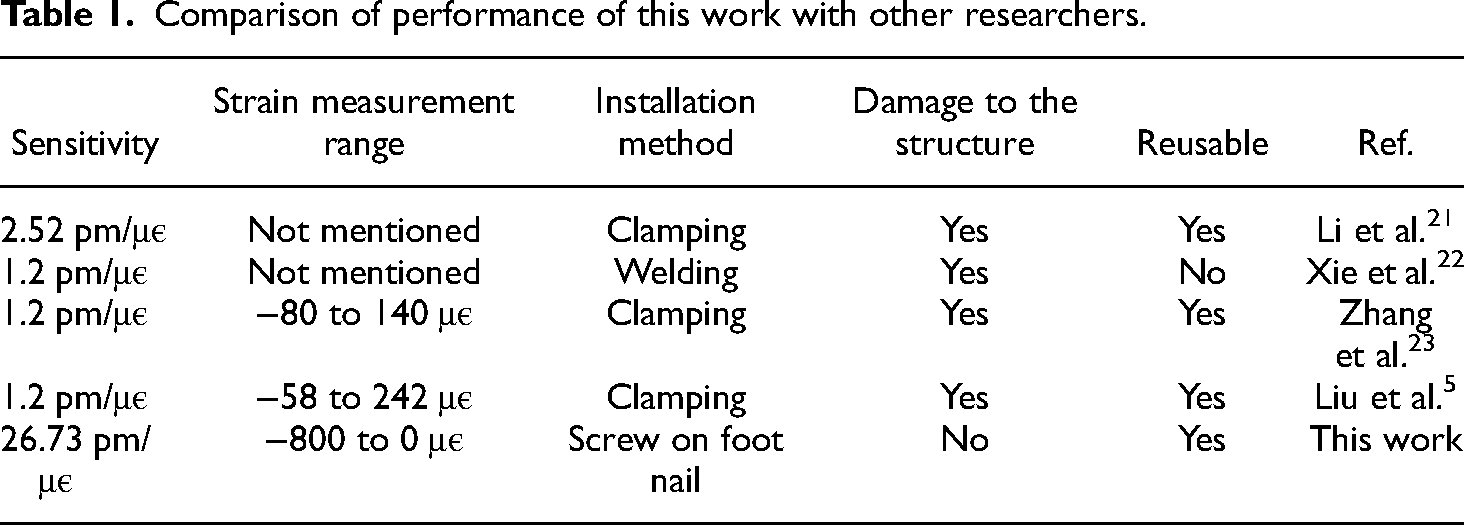
A comparison of this work with other researchers is shown in Table 1 which can be seen that the strain sensitivity, and measure range are better than the references.
Comparison of performance of this work with other researchers.
The repeatability of the strain-sensing FBG was studied by measuring the sensor response in ten complete cycles. It can be seen from Figure 9 that when applied 0 to 400 N tension is to FBG, the strain of the FBG has good repeatability.
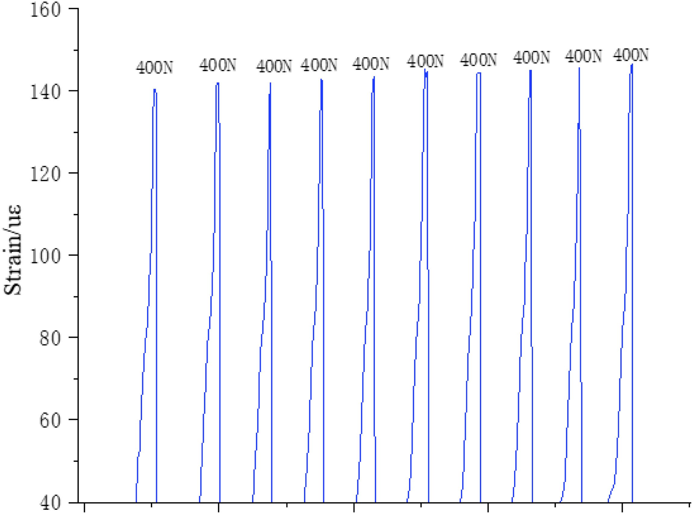
Repeatability of the fiber Bragg grating (FBG) strain sensor.
The Bragg wavelength change of the FBG strain sensor is affected by temperature, a temperature-compensated FBG is arranged in the smart rod freely without being effected by an external force. By doing this, the temperature compensation can be realized by using formula (3)
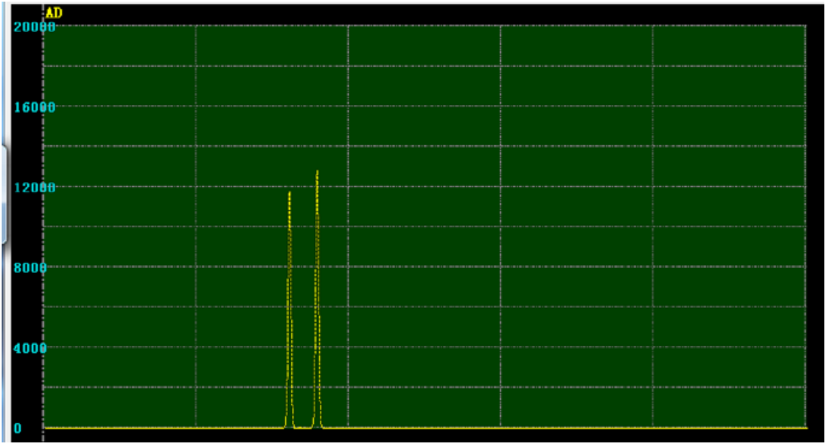
Bragg wavelengths of stress and temperature compensation fiber Bragg gratings (FBGs).
Strain distribution analysis of power transmission tower to be monitored
The power transmission tower to be monitored in this paper is a tension-resistant steel pipe tower (referred to as the large-span power transmission tower) for a 500-kV transmission project on the southeast coast of the Yangtze River. The tower is 204 m high, and the base dimensions are 42 m*42 m. The main members are made of Q235 and Q345 steel. The strain range of the key parts of the tower to be monitored is 2000 με, and the accuracy is required to be 1 με.
In order to analyze the strain distribution, the modal of the large-span power transmission tower was analyzed by ANSYS. BEAM188 element of ANSYS software was used to construct the beam frame model of the large-span transmission tower. By imposing constraints on the tower model, modal analysis is performed to obtain the first-order, second-order, and third-order vibration diagrams of the tower model. As shown in Figure 11, in the first and third models, the maximum displacement of the tower occurs at the head of the tower, while in the second model, the top and middle of the tower are deformed mostly.

Modal analysis of power transmission tower by ANSYS.
The deformation and stress of the power transmission tower were also analyzed and three monitoring points were chosen. The monitoring system contains three smart rods, one home-made FBG demodulator package in a waterproof metal box, two pieces of solar cells (1200*670 mm), and one lead acid battery with 200 AH were used to provide a power supply, communication equipment used to send data to the control center and wind speed sensor to monitor the wind speed to provide climate information. The green box shown in Figure 12(a) is the distribution of points to be monitored and the red box is the location of the FBG demodulator, solar cell, communication equipment, and wind speed sensor, which are fixed at the cross-arm of the power transmission tower through the hoop. Figure 12(b) is the large-span power transmission tower. The strain data collected by FBG is sent to the power line monitoring center through the 4G network, which can monitor and analyze the strain of key parts of the power transmission tower in real-time. Typhoons land frequently in the southeastern coastal areas of China. The large-span electric power transmission tower is a wind-sensitive structure and is more likely to be damaged under extreme conditions such as typhoons. It is of great practical significance for the safe operation of the power transmission tower to evaluate the health of the power transmission tower by monitoring the strain of the key rods.

(a) Distribution of critical parts to be monitored, (b) large-span power transmission tower to be monitored, and (c) installation photos of the monitoring system.
Figure 13 is the strain status of the three points to be monitored from 16:00 on 30 September 2022 to 05:00 on 1 October 2022. It can be seen from the figure that the strain of point 3 which is on the top of the power tower is much larger than the other two points. At midnight on October, the first wind speed increased from 1–2 to 8–10 m/s which caused the strain of the three points to increase largely. The largest strain, with a wind speed of 8–10 m/s, happened on point 3 which indicates with the results of ANSYS, by analyzing the strain change of the main part of the power tower the health state can be determined especially during harsh weather such as typhoon and heavy snow weather. The smart rods were installed on the power tower on 20 August 2022 and until 24 March 2023 (about seven months) still worked properly which shows the high reliability of the sensor.

Strain and speed information of the testing points.
Conclusions
This article proposes a smart rod that can measure the strain of the power transmission tower with high sensitivity by using strain sensitivity enhanced FBG and can be used in harsh environments such as high temperature, high humidity, and coastal areas for a long time. The relationship between applied force and FBG strain is simulated by ANSYS software. The simulation results show that when 1 N force is applied, 0.35 με was produced. By doing experiments, when 1 N force was applied to the smart rod, the actual strain was 1.1 με. The main reason for the error between the simulation and the experimental is that the simulation model simplifies the actual structure. Experimental results show that the sensitivity of the FBG strain sensor is 13 times that of the conventional structure FBG strain sensor, and the linearity between the FBG wavelength change and the load is as high as 0.999. Temperature compensation was realized through temperature measurement FBG installed in the smart rod. The designed smart rod can satisfy the demand for the strain measurement of large spanning power transmission towers. The FBG sensor can easily form a sensor network, which can realize the overall monitoring of large-span structures. At the same time, the FBG has fast transmission speed and large information capacity. Combined with wireless transmission technology, real-time online monitoring was realized.
Footnotes
Declaration of conflicting interests
The author(s) declared no potential conflicts of interest with respect to the research, authorship, and/or publication of this article.
Funding
The author(s) disclosed receipt of the following financial support for the research, authorship, and/or publication of this article: This work was supported by State Grid Shanghai Municipal Electric Power Company Project Relying on New Technology Application to Engineering Infrastructure: Research on Tower Health Monitoring Technology Based on Fiber Bragg Grating and Passive Electromagnetic Super-surface Sensing Technology (Project Number: SGSHGJ00JGJS2100341).
Author biographies
Xue Min, senior engineer, engaged in the management of power transmission and transformation engineering.
Zhu Chun, senior engineer, engaged in the management of power transmission and transformation engineering.
Li Binai, senior engineer, engaged in the management of power transmission and transformation engineering.
Zhao Wenbin, senior engineer, engaged in high voltage technology.
Chu Fenghong, Professor, research interest is optical fiber sensing technology.
Zhu Rui, Associate professor, research interest is kinetic analysis.
Yuan Binxia, Associate professor, research interest is kinetic analysis.