
Abstract
In this paper, a new apodized fiber Bragg grating (FBG) structure, the Chebyshev apodization, is proposed. The Chebyshev polynomial distribution has been widely used for the optimal design of antennas and filters, but it has not been used for designing FBGs. Unlike the function of traditional Gaussian-apodized FBGs, the Chebyshev polynomial is a discrete function. We demonstrate a new methodology for designing Chebyshev-apodized FBGs: the grating region is divided by discrete n sections with uniform gratings, while the index change is used to express the Chebyshev polynomial. We analyze the Chebyshev-apodized FBGs by using coupled mode theory and the piecewise-uniform approach. The reflection spectrum and the dispersion of Chebyshev-apodized FBGs are calculated and compared with those of Gaussian FBGs. Moreover, a sidelobe suppression level (SSL), a parameter of the Chebyshev polynomial, along with the maximum ac-index change of FBGs are analyzed. Assume that the grating length is 20mm, SSL is 100 dB, the section number is 40, and the maximum ac-index change is 2 × 10⁻⁴. The reflection spectrum of Chebyshev apodized FBGs shows flattened sidelobes with an absolute SSL of −95.9 dB (corresponding to SSL=100 dB). The simulation results reveal that at the same full width at half maximum, the Chebyshev FBGs have lower sidelobe suppression than the Gaussian FBGs, but their dispersion is similar. We demonstrate the potential of using Chebyshev-apodized FBGs in optical filters, dispersion compensators, and sensors; Chebyshev apodization can be applied in the design of periodic dielectric waveguides.
Keywords
Introduction
Because of their narrow bandwidth, low insertion loss, high selectivity, immunity to electromagnetic interference, and lack of polarization sensitivity, fiber Bragg gratings (FBGs) have been widely applied as reflectors in fiber lasers, dispersion compensators, and filters in wavelength-division multiplexing (WDM) systems in optical communication. 1 FBGs are also used as photonic sensors due to their high environmental sensitivity, long-term stability, compact size, and low cost. They can be applied for measuring temperature, refractive index, pressure, strain, vibration, and bending,2,3 etc.. Recently, the applications of FBGs in fiber sensing have been developed by many technologies, such as weakly tilted FBGs integrated with black phosphorus, 4 and FBGs inscribed in a thin film deposited on a D-shaped fiber for refractive index sensors. 5 The grating profile can be either a uniform or arbitrary apodization functions (e.g. Gaussian, cosine, raised-cosine, cos2,6 Hamming, Blackman, Tanh, Sinc, Cauchy, 7 or Kaiser windowing functions 8 ). Apodization FBGs have many important applications, such as for dispersion compensation,7,9,10 for delay lines, 11 and as optical filters for WDM systems.6,12–14
Ouellette et al. first proposed a Gaussian apodization function as a dispersion compensator 15 and demonstrated the properties of the device. 16 Thibault et al. numerically simulated chirped FBGs with uniform and Gaussian profiles for efficient compensation. 9 A comparison of the characteristics of various apodization functions in linearly chirped fiber gratings for chromatic dispersion compensators has been presented by Pastor et al.. 7 Ennser et al. revealed that apodized FBGs functioned on the reflection and dispersion characteristics with different apodization profiles. 10
There are many applications of fibers in telecommunications. Marek Życzkowski et al. used optical vortices in fiber optic networks to increase the information flow and the data transmission security. 17 Rui Min et al. presented chirped FBGs inscribed in a microstructured polymer optical fiber for increasing the tunable dispersion. 18 Optical devices for dense WDM systems 19 require optical filters with narrow channel spacing and low insertion loss. Apodized FBGs can achieve high channel isolation with low sidelobes and a well-defined bandwidth. Lima et al. compared and optimized the reflection characteristics of various apodization profiles for FBGs. 6 They showed that FBGs with a Gaussian profile were suitable for an optical filter in a dense WDM system. Lima et al. also demonstrated that Gaussian apodization FBGs with a negative index change mean value can operate as group velocity dispersion compensators. 13 Feced et al. conducted the performance optimization of FBGs with a Gaussian apodization profile in a WDM system. 14
As previously stated, various apodization profiles have been studied and compared to determine their utility in filters of corrugated dielectric waveguides, 8 apodized FBGs for dispersion compensators,7,10 and apodized FBGs for filters in WDM systems. 6 These apodization profiles are continuous functions which mostly are based on sinusoidal or exponential functions. In this paper, we propose, to the best of our knowledge, a new apodized profile for FBGs based on the design of a grating structure with refractive index variation exhibiting the Chebyshev polynomial. We term this as Chebyshev-apodized structure.20,21 The Chebyshev polynomial distribution has been widely used for the optimal design of antennas and filters. 22 For example, the Chebyshev phased array antenna can provide a radiation pattern with equal side lobe levels. 23 It can also be applied in the design of surface acoustic wave (SAW) filters. 24
The Chebyshev polynomial includes the parameters of the number of antennae (n) and the sidelobe suppression level (SSL). The Chebyshev polynomial is not a continuous function. Therefore, the approach for applying Chebyshev apodization to designing FBGs should be different from that of traditional Gaussian apodization. In this paper, we present a methodology for designing Chebyshev-apodized FBGs: First, we divide gratings into n-discrete uniform sections to fit the parameters pertaining to the number of antennas, and second, we use index modulation to express the Chebyshev polynomial. Although several numerical methods have been developed to analyze FBGs such as inverse scattering algorithms 25 and the Genetic Algorithms (GAs), 26 the most common methods for the theoretical analyses of FBGs are based on coupled mode theory, which is a simple and intuitive numerical method that can provide accurate simulated results for FBGs.1,7,12,14,15,27 To analyze n-section FBGs, coupled mode theory with the piecewise-uniform approach (PUA) is applied to designing Chebyshev grating structures in this paper. 27 The SSL and maximum ac-index change of FBGs are analyzed. The calculated reflection spectrum of the Gaussian and Chebyshev-apodized FBGs are illustrated and are compared. Moreover, we simulate the dispersions of the Chebyshev and Gaussian-apodized FBGs with various FWHMs.
The phase mask method is a mature technique to make FBGs, where FBGs can be fabricated in a single mode fiber by combining a KrF 248-nm excimer laser and phase mask writing technique. We can order the phase mask with Chebyshev profiles to make Chebyshev-apodized FBGs; however, it is too costly to make a customized phase mask. By utilizing the translation stage, shifting the narrow laser beam, and controlling the exposure time in the fiber, a Chebyshev grating profile could be fabricated.
A key aspect of the Chebyshev-apodized FBGs is to produce a flattened sidelobe and to design the sidelobe suppression level. These properties can provide significant advantages in optical communication system and improve sensing accuracy in FBG sensors. Our goal is to achieve more efficient FBG design for applications as filters, dispersion compensators, reflectors, and sensors. Moreover, the methodology can be applied for designing periodic dielectric waveguides for filters, distributed Bragg reflector lasers, and dispersion compensators.
This paper is organized as follows. In Section 2, a brief introduction of the couple mode theory is presented. In Section 3, the reflection spectrum of Chebyshev-apodized FBGs with parameters of Chebyshev polynomial are analyzed and discussed. Moreover, the reflectivity and dispersion of Chebyshev-apodized FBGs also make comparisons with those of Gaussian-apodized FBGs in Section 3. Finally, conclusions are given in Section 4.
Mathmetical formulation
In this paper, we use coupled mode theory with the piecewise-uniform approach
27
to analyze Chebyshev-apodized FBGs. Assume that a time-harmonic wave propagates in the z-direction as exp(iβz-iωt), where β is a propagation constant, and ω is the angular frequency. An apodized FBG was applied to reduce the high sidelobes on the high-frequency side. Therefore, the refractive index of the fiber Bragg grating can be expressed as follows:
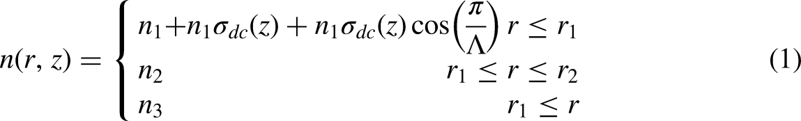
The coupled equations can be written as follows:


By matching the boundary condition at each interface of sections, the transmission and reflection efficiencies can be obtained. The group delay Vg and dispersion D can be expressed as follows
28
:

where β is the propagation constant, ω is the angular frequency, λ is the wavelength, and c is the velocity of light in vacuum. The shape factor is defined as follows:

where BW20dB is a bandwidth of − 20 dB, and BW3db is a bandwidth of − 3 dB. Figure 1 shows the Block diagram of calculating the transmission and reflection efficiencies, group delay, and dispersion of Chebyshev-apodized FBGs. The detailed description of coupled mode theory with the piecewise-uniform approach can be referenced from the paper presented by Sun et al. 27
Block diagram for calculating the transmission and reflection efficiencies, group delay, and dispersion of Chebyshev-apodized FBGs.
After the Chebyshev polynomial is used to design a phased array antenna, the number of antennas (n) and SSL can be determined. As previously stated, the Chebyshev polynomial is not a continuous function. Assume that the number of antennas represents the number of uniform gratings. Using Chebyshev apodization, we divide gratings into n-discrete uniform sections. Moreover, for the design of SAW devices, the duty cycle is selected to be a Chebyshev modulation term.
24
For FBGs, we use an “ac” index change
Results
A step-index fiber is used in our design. For the fiber structure, the radiuses of the core (r1) and cladding (r2) are 2.5 μm and 62.5 μm, respectively.
29
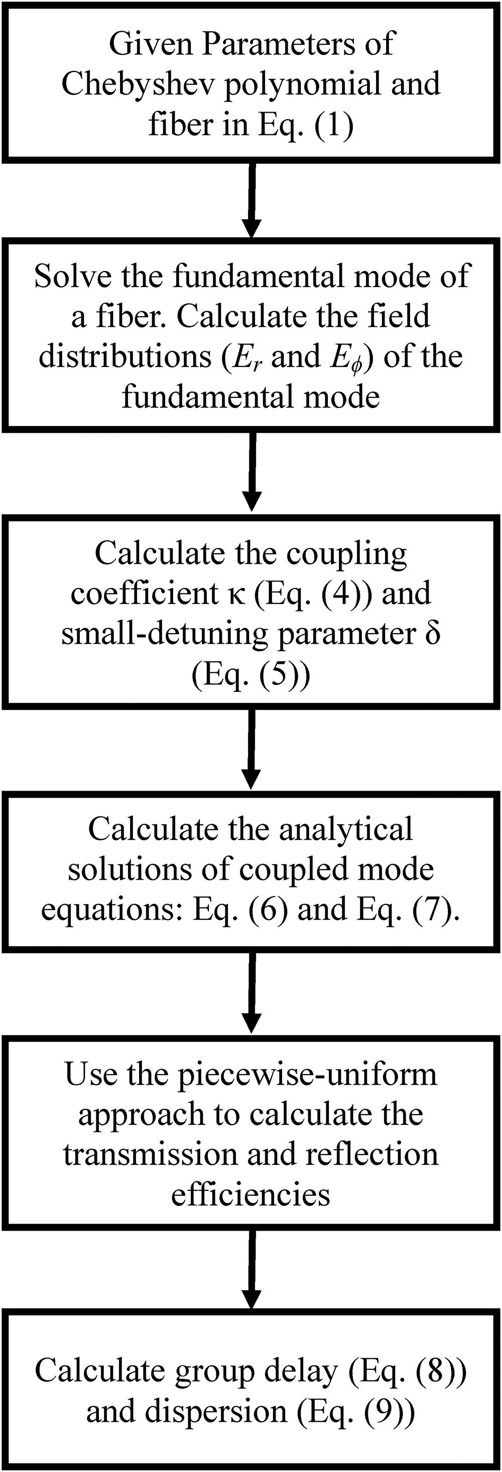
The refractive indices of the core (n1), cladding (n2), and surrounding region (n3) are 1.458, 1.45, and 1, respectively. Figure 2 shows the envelope profile of a Chebyshev apodization with an SN of 40 (SN = 40) and an SSL of 100 dB. Assume that the total length of the FBG is 20mm,
30
and that the length of each section is 0.5 mm. Figure 2 presents the envelope profile
dc-index change of a chebyshev profile with 40 section uniform gratings, where
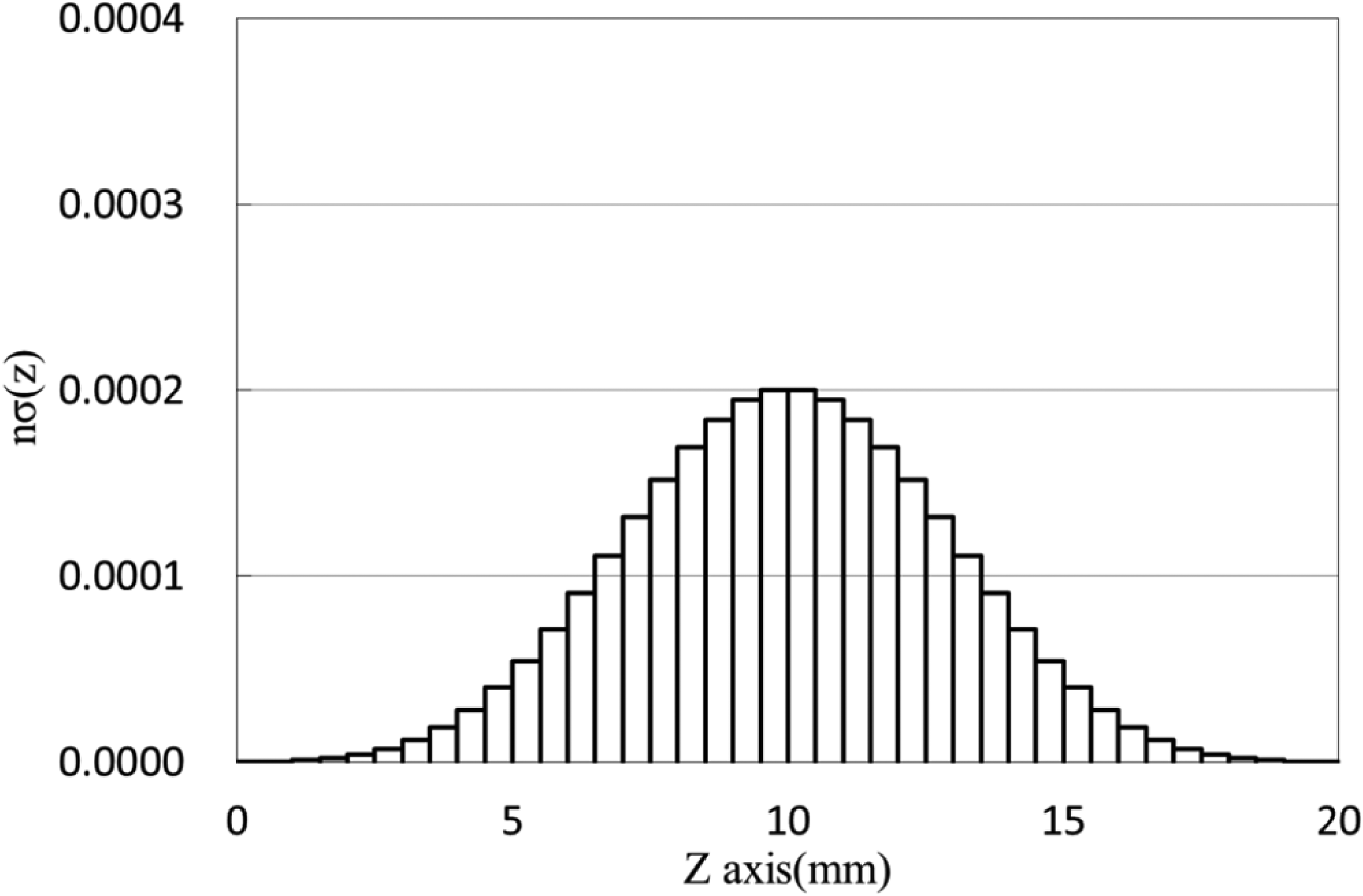
We use the PUA to calculate the spectrum of apodized FBGs. Figure 3 shows the transmission and reflection spectra of Chebyshev-apodized FBGs. The reflection spectrum of apodized FBGs is not symmetric in the resonant region due to the non-uniform index change

Transmission and reflection spectra of the chebyshev-apodized structure (parameters presented in Figure 1).
The symmetric transmission and reflection spectra are determined through two approaches. Firstly, the apodized structures with a zero dc-index change are used. Figure 4 shows that the constant dc-index change (


Index change of a chebyshev profile with 40section uniform gratings and constant dc-index change, where

The transmission and reflection spectra of Chebyshev apodization with a zero-dc index change and with grating period variation are shown in Figure 6. The grating structure in Figure 6 is the same as the structures in Figure 4 and Figure 5. We find that the transmissivity and reflectivity of the two grating structures are overlapping and symmetric. The − 3-dB resonant region is from 1539.1845 to 1539.3175 nm, where the − 3-dB bandwidth of the reflection spectrum is 0.133 nm, and the − 20-dB bandwidth is 0.239 nm. The central wavelength at resonance is 1539.251 nm. The sidelobe suppressions show nearly equal sidelobe levels on the two sides of resonance, and are approximately 100 dB corresponding to wavelengths of 1539.94 and 1539.58 nm.
Next, we vary the parameters of Chebyshev-apodized FBGs. For simplicity, the structure in Figure 4 is used for simulations. Figure 7 shows the reflection spectrum of Chebyshev-apodized FBGs where the SSLs are 60, 80 and 100 dB, the SN is 40, and

The reflection spectrum of chebyshev-apodized structure with SSL = 60 dB (red line), SSL = 80 dB (green line) and SSL = 100 dB (blue line), where SN = 40, and
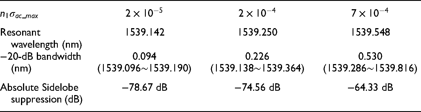
Figure 8 shows the reflection spectrum of Chebyshev-apodized FBGs with

Reflection spectrum of a chebyshev-apodized structure with
Resonant wavelength, − 20-dB bandwidth, and absolute sidelobe suppression level of a chebyshev-apodized structure with
The spectrum of Chebyshev-apodized FBGs with different gratings lengths are analyzed. Figure 9 shows the reflection spectrum of Chebyshev-apodized FBGs with the grating lengths of 5 mm, 10 mm, and 20 mm, where the SSL is 100 dB, the SN is 40, and
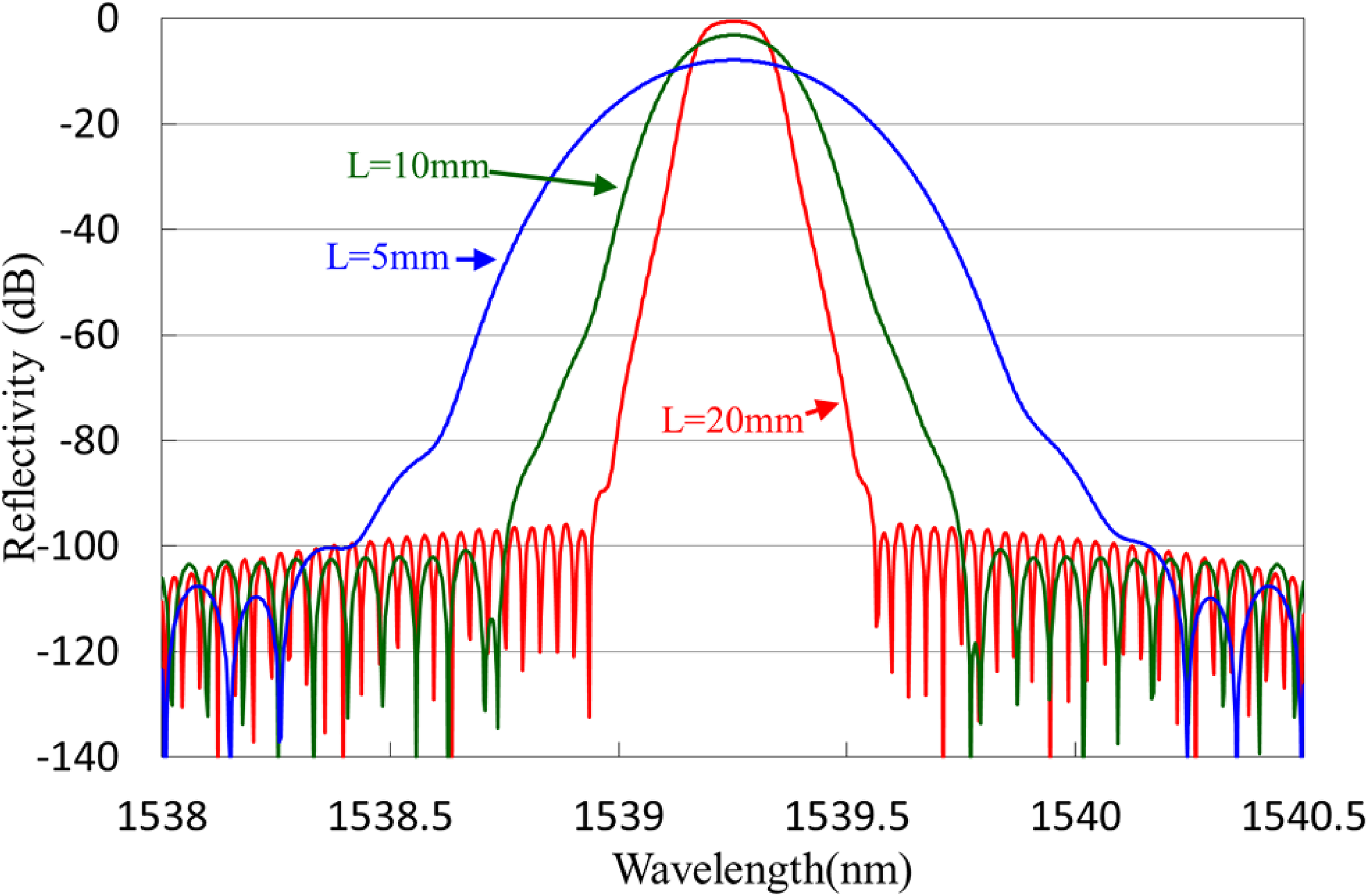
Reflection spectrum of a chebyshev-apodized structure with the gratings length of 20 mm, 10 mm, and 5 mm. The
We compared the reflectivity and dispersion of the Chebyshev-apodized profile (SSL = 100) with that of the Gaussian-apodized profile of FBGs, where the section number is 40, and
Figure 10 shows the reflectivities of Chebyshev (blue line for SSL = 100 dB), Gaussian grating structures with FWHM = 7mm≈L/3 (green line), Gaussian grating structures with FWHM = 10mm = L/2 (red line), and Gaussian grating structures with FWHM = 20mm = L (purple line). The absolute sidelobe suppression level on the two sides of resonance at an SSL of 100 dB for Chebyshev apodization are − 95.9 B (approximate to − 100 dB), whereas the sidelobe suppressions are approximately − 62.5 dB, − 34.4 dB, and − 11.6 dB for Gaussian apodization at FWHM≈L/3, FWHM = L/2, and FWHM = L, respectively. The results show that at a similar FWHM, the Chebyshev-apodized FBGs could provide higher sidelobe suppressions level than Gaussian-apodized FBGs could. Moreover, the sidelobe spectrum of Chebyshev apodization is approximately − 96 dB ranging from a wavelength of 1538.85 to 1538.55 nm. For the Gaussian-apodized FBGs, the sidelobe spectrum is from − 62.5 dB to − 72 dB with FWHM = 7 mm, from − 34.4 dB to − 46 dB with FWHM = 10 mm, and from − 11.6 dB to − 27.5 dB with FWHM = 20 mm. The sidelobe level of Chebyshev apodization is flatter than that of Gaussian apodization.

Reflection spectra of chebyshev-apodized (blue line for an SSL of 100 dB) and Gaussian-apodized FBGs (green line for FWHM = 7 mm ≈ L/3, red line for FWHM = 10 mm = L/2, and purple line for FWHM = 20 mm = L).
The dispersion spectra of the Chebyshev and Gaussian grating structures are shown in Figure 11, where the blue line denotes Chebyshev apodization (SSL = 100 dB), the green line denotes Gaussian apodization with FWHM≈L/3, the red line denotes Gaussian apodization with FWHM = L/2, and the purple line is for FWHM = L. The insect of Figure 11 is the dispersion spectrum of FWHM = L. The dispersion of Chebyshev grating structures with SSL = 100 dB is similar to that of Gaussian structures with FWHM≈L/3. The maximum magnitude of dispersion for Chebyshev and Gaussian FBGs with FWHM≈L/3 are approximately 0.631 ps/nm·km. Note that the maximum magnitude of dispersion of Gaussian FBGs with FWHM = L/2 (dispersion = 1.872 ps/nm·km) is three times larger than those of Chebyshev and Gaussian FBGs with FWHM≈L/3 (dispersion = 0.631 ps/nm·km).

Dispersion spectra of the chebyshev-apodized (blue line) and Gaussian-apodized FBGs. The green line represents FWHM = 7 mm, the red line denotes FWHM = 10 mm, and the purple line denotes FWHM = 20 mm. The insect is the dispersion spectrum of FWHM = 10 mm.
Table 2 shows the − 3-dB bandwidth, the − 20-dB bandwidth, the shape factor (defined as the 20-dB bandwidth divided by the 3-dB bandwidth) of four grating structures, and the maximum magnitude of dispersion. The − 3-dB bandwidths of the Chebyshev-apodized FBGs (∼0.133 nm) are wider than those of the Gaussian-apodized FBGs (∼0.128 nm). The shape factor of 1.797 for the Chebyshev apodization is worse than that for Gaussian apodization at FHWM = 10 mm (1.656) and better than that for Gaussian apodization at FWHM = 7 mm (1.906), while Gaussian apodization at FHWM = 10 mm has the smallest shape factor of 1.125 in Table 2. Moreover, as shown in Table 2 and the inset of Figure 11, Gaussian FBGs with FWHM = L has the largest maximum magnitude of dispersion (dispersion = 11.06 ps/nm·km).
Simulated results for the bandwidths, the shape factor, and the maximum magnitude of dispersion of chebyshev-apodized FBGs and Gaussian-apodized FBGs.

Conclusions
In this paper, Chebyshev index modulation is applied to design FBGs. The reflection spectrum and the dispersion of a Chebyshev apodization profile with 40 grating sections are calculated. We vary the SSL and maximum ac-index change (
Footnotes
Acknowledgments
The authors thank Prof. Ruyen Ro, Prof. Chung-Long Pan (I-Shou University), and Wen-Fung Liu (Feng Chia University) for taking part in the discussions on Chebyshev apodization. This work was partially supported by the Ministry of Science and Technology of the Republic of China under grants MOST 108-2221-E-214-029-MY2, MOST 110-2221-E-214-018, and MOST 108-2221-E-214-030, and by I-Shou University under grants ISU100-08, and ISU-108-01-01A.
Declaration of conflicting interests
The author(s) declared no potential conflicts of interest with respect to the research, authorship, and/or publication of this article.
Funding
The author(s) received no financial support for the research, authorship, and/or publication of this article.