
Abstract
Blisks are not easily machined because of their complex curved surfaces and the high-precision requirements of surface machining. Lightweight alloy materials with superior mechanical properties, such as titanium alloy and stainless steel, are popular material choices for manufacturing turbine blisks. However, these materials are difficult to cut and require advanced machine tools and processing technologies. Because aerospace-grade parts are complex and require precise dimensions and high surface quality, machining these parts by using three-axis machine tools is difficult. Using multi-axis machine tools for the machining of complex parts can cause the achievement of precise dimensions, high quality, and the required surface roughness. In the multi-axis machining of aerospace blisks, tool path planning is considered the most difficult task. In this study, we examined the implementation of five-axis machining technology for the manufacturing of an aerospace blisk. Processing modules from computer-aided manufacturing software (NX10) are used for five-axis tool path generating, and 5-axis machining numerical control code is generated through post-processing calculations. Solid cutting simulation software (VERICUT) is used to verify whether tools exhibited overcut or interference. A sensory tool holder (SPIKE) is used to analyze cutting force during the rough machining of a blisk. The sensory tool holder is also adopted to evaluate the spindle runout and tool holding status. In order to obtain a consistent cutting allowance and surface accuracy, the online measurement system is used to generate a measurement path for semi-finish and finish machining. The real cut is performed with SUS304 and demonstrates the practical application. Through improvements in process planning, the machining time was shortened by 16.5%.
Introduction
Aerospace blisks are a key component for the aerospace, automobile, refrigeration, and air-conditioning industries. The production of blisks is time-consuming because they have twisted complex curved surfaces and are made of difficult-to-cut materials. These components are commonly composed of highly resistant superalloys; in order to satisfy the extreme working conditions, they have to keep mechanical strength during their useful life. These materials, such as titanium alloy and stainless steel, are difficult to machine and require advanced machine tools and adequate cutting parameters. Blisks are difficult to repair when damaged. Strict quality control can ensure the safety and reliability of blisks; however, such quality control entails an increased cost
Kang 1 introduced the constant scallop height method for generating the milling path. This method effectively shortens the length of the tool path and achieves a uniform machining surface by controlling the chordal deviation. Liu 2 conducted research on the path planning of a spherical and curved end mill cutting surface and proposed a method of integrating the iso-scallop height and chord error for planning the tool path. This tool path planning method allows for the control of the roughness uniformity and cutting geometry precision during the cutting of curved surfaces. Zhang 3 proposed a five-axis curved surface machining tool for forward step cutting to control the chord height error between each moving point of the tool on the cutting path. This method allows for control of the tool axis orientation angle within the allowable range. She 4 proposed a five-axis machining method for spatial cams. Chen 5 used the C + + language to develop an axial flow blade-machining module, which includes options for data input, tool position calculation, collision checking and correction, and data output. By integrating processing rules into this module, tool position data can be generated efficiently through calculations. Lee et al.6, 7 presented an interference-free toolpath generating method for multi-axis machining of a cylindrical cam. Based on the envelope theory, the cutter location for multi-axis NC machining using cylindrical-end mill is derived and the cutting path sequences with the minimum lead in and lead out are planned. To comprehend the design concepts of the impeller and create the capacity of the manufacturer, the authors of this paper regenerated the impeller profile and study the five-axis NC programming. Through the application of CAM software, the interference-free toolpath and the cutter location for five-axis NC machining are generated. Sergej et al. 8 developed a method to simultaneously increase the accuracy and decrease the calculation time for complex tool path programming in multi-axis machining centres. Industrial tests reveal a 70–80% reduction in NC programming time of parts with complex surfaces, and a reduced machining time of approximately 40–50% using basic high-speed cutting methods and custom-made tools. Calleja et al. 9 consider the existing demand for better manufacturing technologies. A study case based on an Inconel 718 blisk finishing operations study is developed. A static model for machining forces prediction is developed to finally validate it with the real machining forces measured during the machining process. Egoitz et al. 10 proposed a method for a reliable machining process of IBRs. Geometric, process simulations and machine kinematics simulations were considered in this paper to improve part quality and optimizing each of the three machining phases machining set up. In addition, a mechanical analysis was developed to simulate the cutting forces. Several impeller and blisk geometries were milled to validate and optimize the process. Abele et al. 11 presented associated experimental investigations and a process simulation to design a suitable process. Process improvement is achieved using hybrid machining, based on inductive heating and cryogenic cooling to increase productivity; results show an increased material removal rate and a reduction of tool wear when machining Ti6Al4V integral components. Gdula et al. 12 determined the influence of a toroidal cutter axis orientation and a variable radius of curvature of the machined contour of the sculptured surface of the turbine blades on the five-axes milling process. Simulation and experimental research performed in this work are aimed to determine the relationship between the parameters of five-axes milling process and the shape and dimensional accuracy of the curved outline of Inconel 718 alloy workpiece. Stratogiannis et al. 13 discussed the best milling strategies, optimum cutting conditions, and appropriate cutting tools were selected for each of the three machining phases roughing, semi-finishing, and finishing for impeller. Then, an experimental investigation was conducted, especially for the optimum process conditions during the finishing of impeller blades, using Taguchi L16 orthogonal array. Haizea et al. 14 presented a review of the last advances for Integrally Bladed Rotors (IBR) manufacturing and repairing processes. Liu 15 performed continuous path prediction to perform online measurements (i.e. continuous slope). After the measurement, a cubic spline curve was fitted in the X-direction and Y-direction to get the normal vector and achieve probe compensation. Hao 16 integrated an OMP400 touch trigger probe system with a four-axis computer numerical control (CNC) engraving machine. A fan blade was used as a carrier to conduct inspections during machining. For problems such as interference and obstacle avoidance, solutions included the use of algorithms, obstacle avoidance procedures, and path planning to achieve safety and precision requirements. Isamu et al. 17 realized the automation of planning for on-machine measurement. Where measurement is conducted at the time during the machining process based on process planning. when a machining abnormality is detected based on the measurement results, the proposed system automatically judges whether to stop machining or to re-machine the affected region. Nakamoto et al. 18 developed a novel compensation method by non-contact measurement with a laser imaging device. In order to improve compensation performance, a laser imaging device is calibrated on an ultraprecision machine tool. The proposed method enables direct detection of the actual tool position and calculation of the tool centre point coordinate on the machine coordinate system. By modifying an NC programme, the tool setting errors can be compensated. Chen et al. 19 demonstrated the cutting force validation and volumetric Errors compensation of thin workpieces with a sensory tool holder. The cutting forces were measured by a sensory tool holder and the data coordinate transformation between the tool and the workpiece was established. Modified tool paths for compensation volumetric errors were built according to the deformation data as a CL (cutter location) file. The result shows that the presented method successfully improved machining precision and processing efficiency. Schörghofer et al. 20 developed a sensor integration for a tool holder SK45 in order to avoid dynamic instabilities or process failures. This sensor system integration attached to the tool holder is to gain more detailed process information. It's able to detect chatter vibrations in an early stage.
The main goal of this study is to shorten the blisk machining time through the analysis of cutting forces and five-axis path improvement. A sensory tool holder is used to measure cutting force during the rough machining. It is also adopted to evaluate the spindle runout and monitor tool holding conditions so as to keep experiment validity. To avoid collision between all machine tool components, the generated NC codes are verified before actual machining through solid cutting simulation. To ensure the machining quality of the blisk, the virtual geometric error is analyzed and used as a basis for generating an appropriate tool path, and then the online measurement of real machining is conducted during the semi-finish machining stage and error compensation is performed during the finish machining stage.
Experimental set-up and method
Aerospace-grade blisks are large and require high-precision machining. Because of the complex curved surfaces of these blisks, five-axis machining is the primary method used to manufacture them. Rough machining can shorten the total machining time. In this study, the SPIKE software and a sensory tool holder got from Pro-micron GmbH were used to conduct cutting force analysis in five-axis rough machining to aid in cutting tool selection and machining path improvement. Figure 1 shows the research flowchart.

Research flowchart.
Because the outside diameter of the required blisk was 588 mm, a horizontal five-axis machining centre was used for machining. The machining process involved rough machining, semi-finish machining, and finish machining. The process planning flowchart is displayed in Figure 2. To achieve machining safety and dimension accuracy, the VERICUT numerical cutting simulation software was used to conduct a cutting simulation. This simulation ensured that no collision and interference occurred between tools and workpieces on the tool path.

Flowchart for blisk tool path planning.
Blisk and machining equipment
Models of the hub, blade, and other related parts of the blisk were created using computer-aided design (CAD) and computer-aided manufacturing (CAM) software. The designs of these models were based on the parameters presented in Table 1. The CAD model of the blisk is displayed in Figure 3.
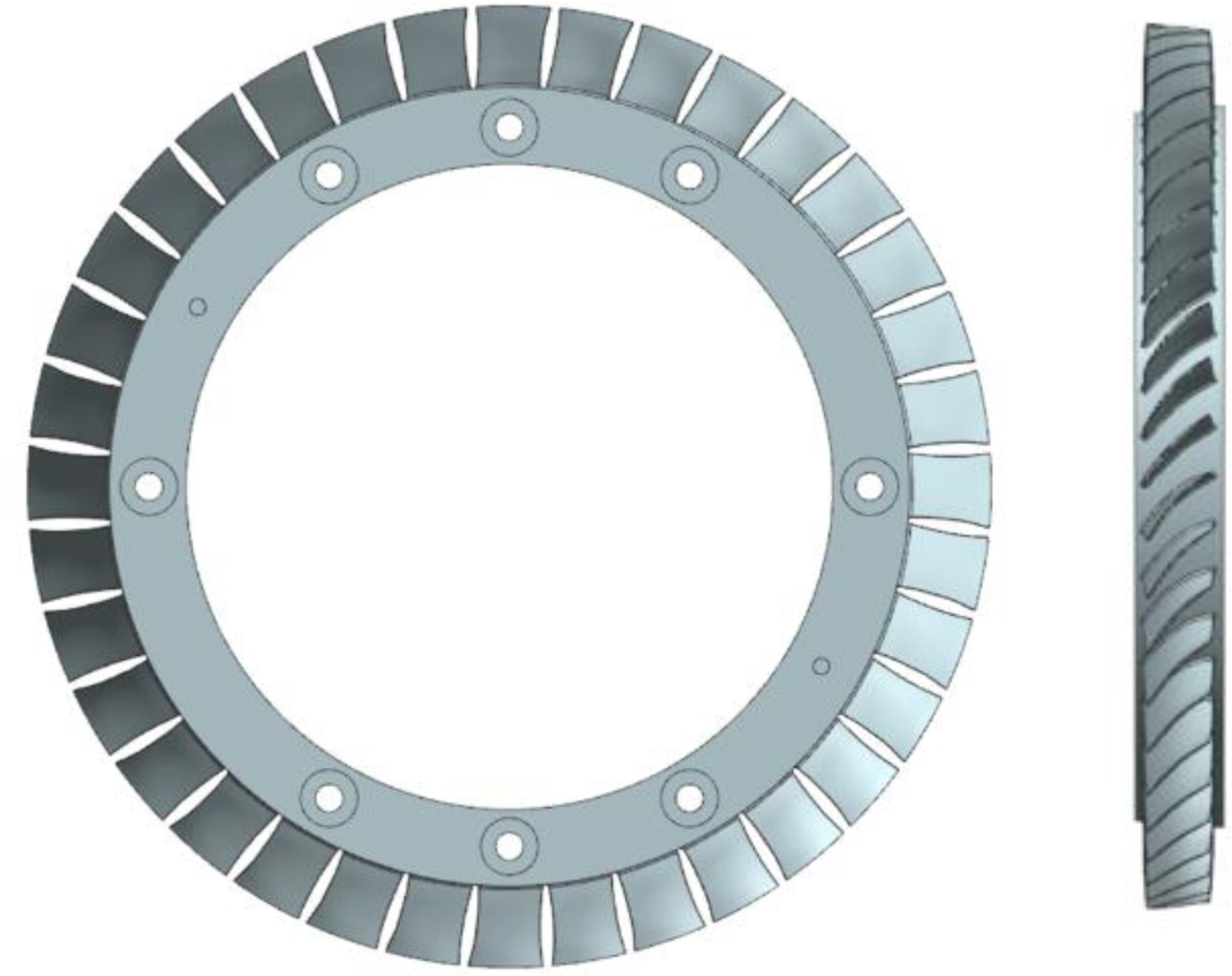
CAD model of the blisk.
Design parameters of the blisk.

A horizontal five-axis machining centre (CK-Type) was used for machining the blisk. This type of machining centre has excellent static and dynamic performance and can be operated for a long time. A large machining centre can machine large aerospace-grade parts, such as blisks. A horizontal five-axis machining centre is depicted in Figure 4.

Horizontal five-axis machining centre.
During machining, a workpiece must be securely held in a specified position. The design and use of a fixture can meet this need. The purpose of a fixture is to hold and position a workpiece at a precise position. Figure 5 displays the fixture model, and Figure 6 illustrates the assembly of the blisk and fixture.
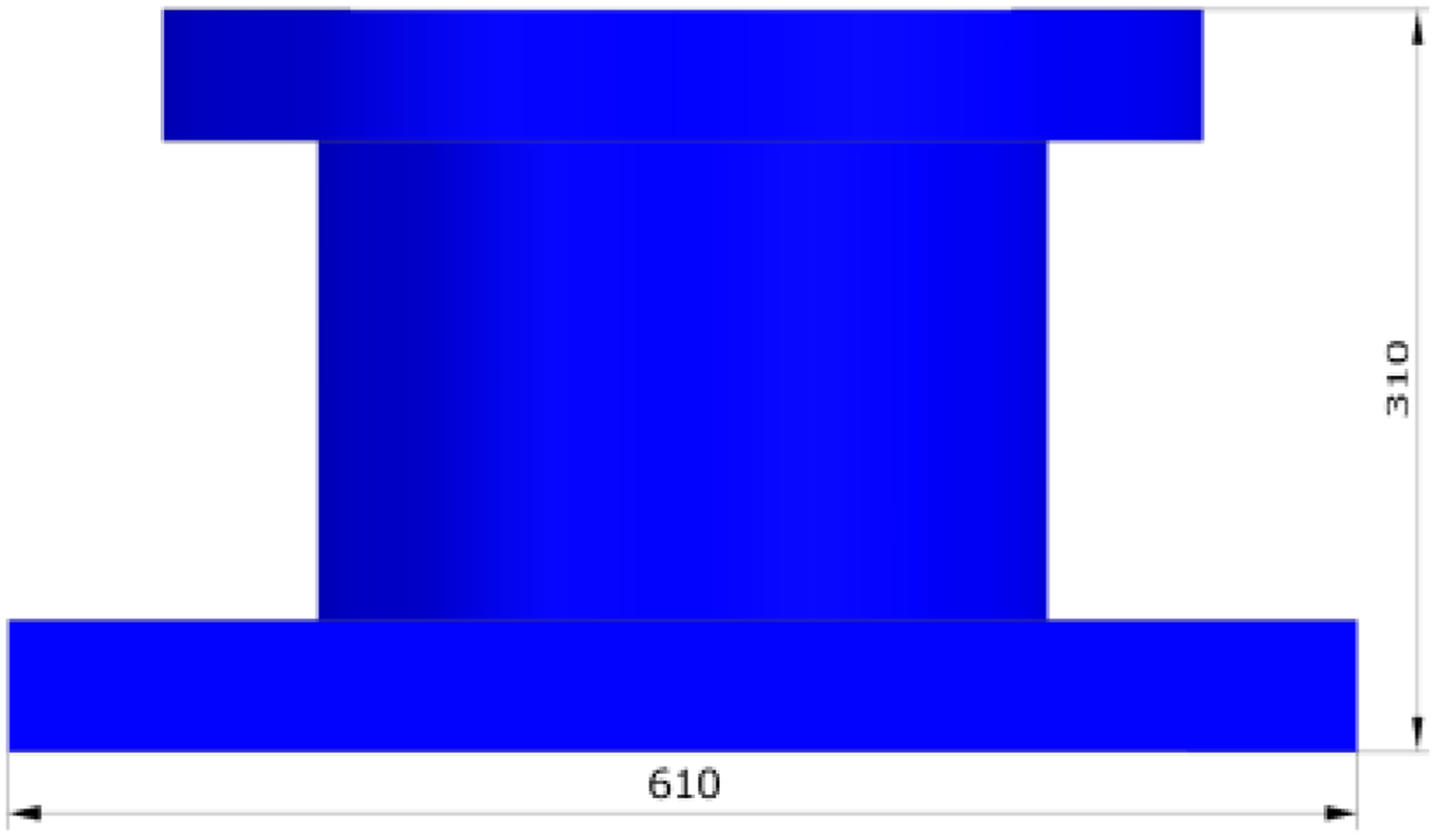
Fixture model.

Blisk and fixture assembly.
Cutting condition and verification
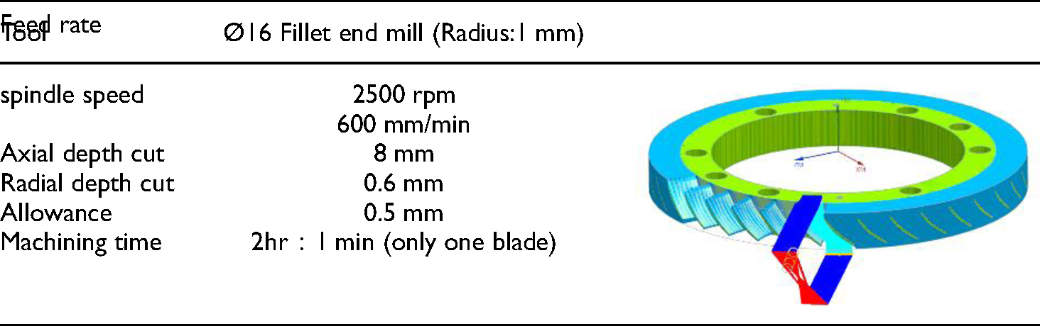
A NX10 multi-blade module was used for tool path planning. This module requires the specification of the process parameters presented in Tables 2–7.
Cutting parameters and tool path for rough machining.
Cutting parameters and tool path for the semi-finish machining of the blade.

Cutting parameters and tool path for the semi-finish machining of the hub.

Cutting parameters and tool path for the finish machining of the blade.

Cutting parameters and tool path for the finish machining of the hub.

Machining cutting parameters and tool path for the fillet finishing of the blisk.

After the completion of tool path coding, the tool path code was converted into an NC file, and VERICUT was used to conduct tool path cutting simulation (Figure 7). A virtual five-axis machine tool with the same controller, shaft direction, number of tools, tool parameters, fixture position, and bank as those of the real machining tool must be constructed to minimize the discrepancies between the simulated and real cutting.

Cutting simulation with VERICUT. (a) Rough machining; (b) Semi-finish machining; (c) finish machining.

Schematic of the adopted sensory tool holder.
Sensory tool holder
A sensory tool holder manufactured by Pro-micron GmbH was used to measure the cutting force. Table 8 lists the specifications of this tool holder. Because the sensor is located inside the tool holder, axial forces, torques, and bending moments can be measured in the X-direction and Y-direction during cutting. The adopted sensory tool holder is illustrated in Figure 8.
Bending moment with a 0.003-mm runout.
Specifications of the adopted sensory tool holder.

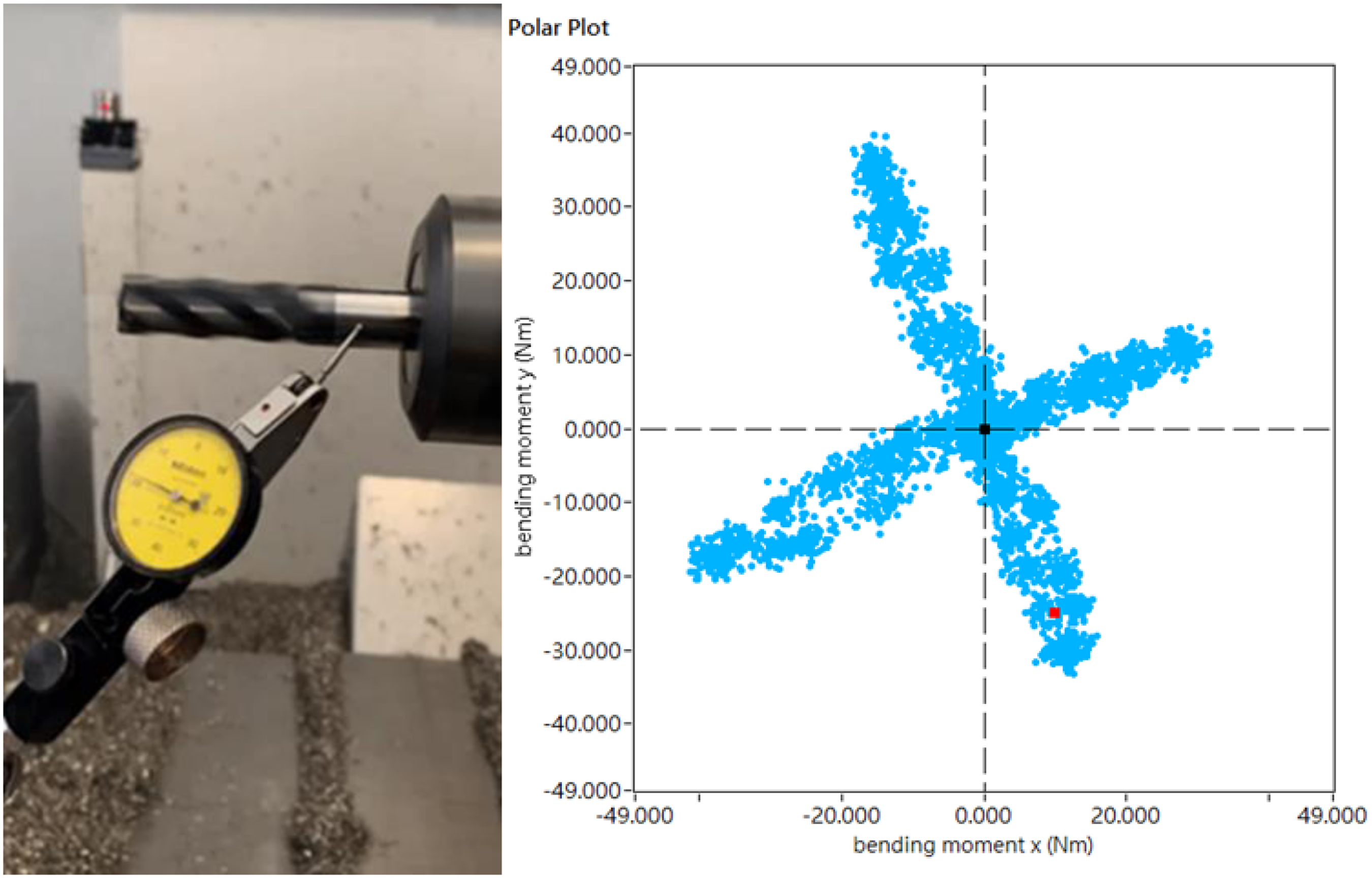
Before conducting a cutting force experiment, the spindle runout must be confirmed to be within the acceptable tolerance to ensure machining accuracy, as depicted in Figure 9. A sensory tool holder was used for cutting, and the surface roughness was measured. Figure 10 shows the workpiece surface after cutting. Figure 11 depicts the results of the surface roughness measurements.

Workpiece surface after cutting with a 0.003-mm runout.

Results of surface roughness measurement with a 0.003-mm runout.
Results of rough machining analysis under a machining allowance of 0.5 mm.
Online measurement path planning
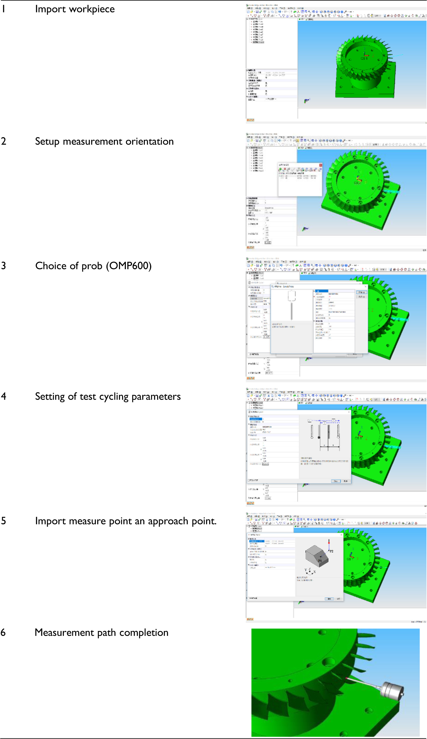
For online after-machining inspection, the best measurement path was planned according to the geometry of the blisk. A Renishaw OMP600 probe was integrated with the five-axis machine tool to perform workpiece position coordination, conduct online measurements, and modify a five-axis machining path to increase the machining accuracy and process efficiency. The AE-pro online measurement system (Renishaw) was used to plan a measurement path for semi-finish and finish machining. A CAD file was converted into an STP file and imported into AE-pro. The parameters that must be specified in the finishing include the measurement orientation, probe type, cycle parameter, and measurement coordinates. The process planning of online measurement are presented in Table 9.
The process planning of online measurement.
Results and discussion
Soild cutting simulation
A NX10 multi-blade module was used to perform tool path planning. When adjusting related settings, it becomes essential to know whether the parameter settings may affect the variation of the tool path and if the tool dodge angle affects the tool without a blade.
To avoid collisions between various parts of the machining tool, over-travel, or NC code errors, the NC code was imported into the VERICUT software for verification and comparison analysis before the start of machining. Settings such as the machine tool collision inspection and travel limit were adjusted. In machining error analysis, the AUTU-DIFF module of VERICUT® software is adopted to compare a design model to the “as-machined” VERICUT solid model to automatically detect differences and protect against gouges. Figures 12–14 reveal the result of error analysis in different machining processes. The machined allowances are specified as 0.5 mm and 0.2 mm respectively for the rough and semi-finish process.

Results of semi-finish machining analysis under a machining allowance of 0.2 mm.

Results of finish machining analysis.

Machining tools paths for five-axis slot and side milling.
Cutting force analysis
The five-axis cutting force
Three fillet end mills (with helix angles of 35°, 38°, and 45°) were used for five-axis rough machining. The tool geometries and coatings of these tools were the same, and the same five-axis machining cutting paths were used for the tools (Figure 15). The material of blisk is SUS304 in this paper. The cutting process involved slot milling and side milling. A sensory tool holder was used to measure the bending moments experienced by each tool during slot milling and side milling. The measurement results for slot milling are presented in Figures 16–18, and the measurement results for side milling are presented in Figures 19–21. Tables 10 and 11 present comparisons of the results got with the three tools for slot milling and side milling, respectively.
Bending moment of the tool with a helix angle of 35° for slot milling.

Bending moment of the tool with a helix angle of 38° for slot milling.

Bending moment of the tool with a helix angle of 45° for slot milling.

Bending moment of the tool with a helix angle of 35° for side milling.
Bending moment of the tool with a helix angle of 38° for side milling.

Bending moment of the tool with a helix angle of 45° for side milling.

Axial holding force of the tool.
Comparison of the results obtained with the three tools for slot milling.

Comparison of the results obtained with the three tools for side milling.

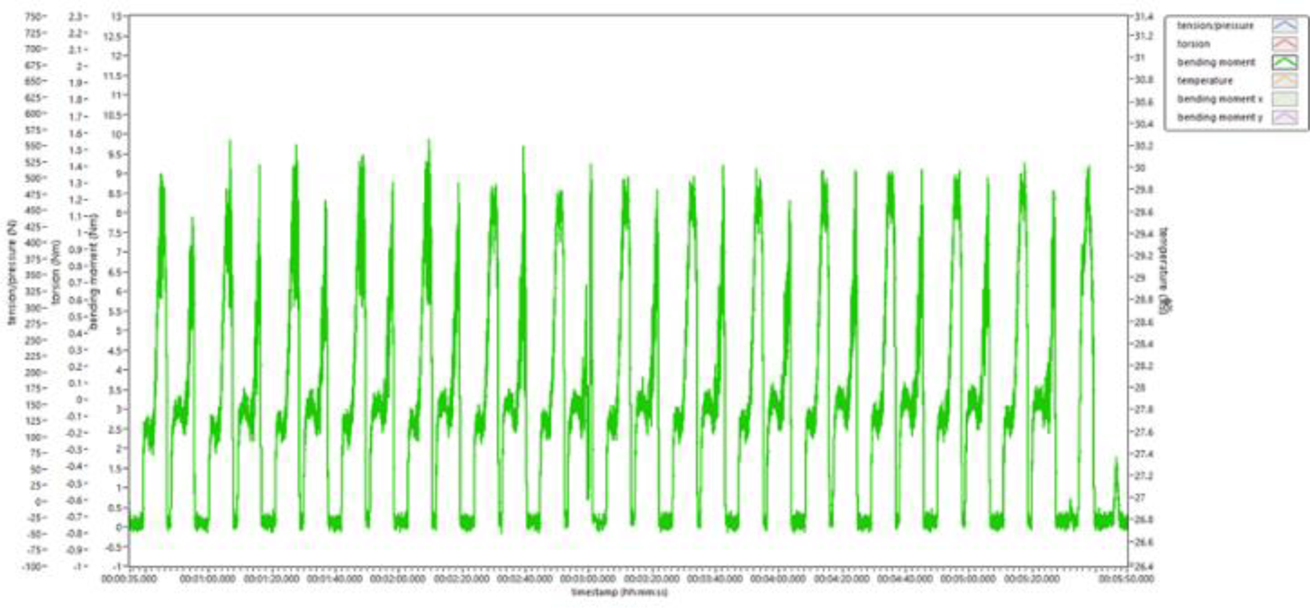
Tool holding force
In general, a fillet end mill was pulled toward the workpiece during the milling process. The sensory tool holder was used to measure the axial force when the tool was in operation. Through this measurement, the tool holding condition could be determined and the cutting condition could be monitored to avoid damage caused by the pulling of the fillet end mill, which may cause overcutting and inadequate surface roughness. A negative axial force suggested that fillet end mill pulling had occurred.
Through sensory tool holder measurements, the axial holding force was measured to be 700 N. (Figures 22, 23). The sensory tool holder could simultaneously monitor the forces in the X-direction and Y- direction, and the axial force. The axial forces were positive in all the experiments, which suggested that tool pulling did not occur. Figures 23–28 show the axial force of each fillet end mill during slot and side milling.

Axial force during slot milling for the fillet end mill with a helix angle of 35°.

Axial force during side milling for the fillet end mill with a helix angle of 35°.

Axial force during slot milling for the fillet end mill with a helix angle of 38.

Axial force during side milling for the fillet end mill with a helix angle of 38°.

Axial force during slot milling for the fillet end mill with a helix angle of 45°.

Axial force during side milling for the fillet end mill with a helix angle of 45°.

Chatter marks caused by spindle runout.
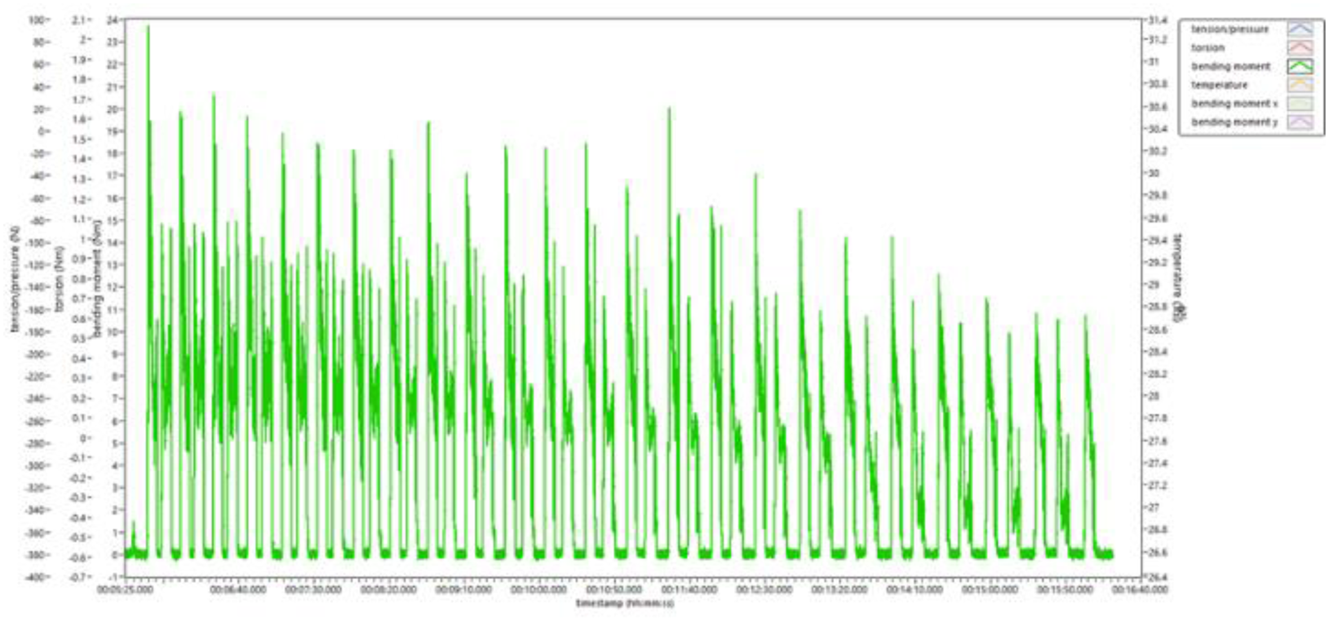
Spindle runout analysis
The sensory tool holder was used to conduct a real cutting experiment for large and small spindle runouts (0.5 and 0.003 mm, respectively). For the large spindle runout, obvious chatter marks were observed on the cutting surface (Figure 29). The force and bending moment experienced by the blade in the X-direction and Y-direction were uneven for the large spindle runout (Figure 30). Thus, the surface roughness values got under the large and small spindle runouts were significantly different.

Force on the cutting tool in the X-direction and Y-directions for (a) normal forces and (b) runout forces.
CAM-generated one-step machining method.
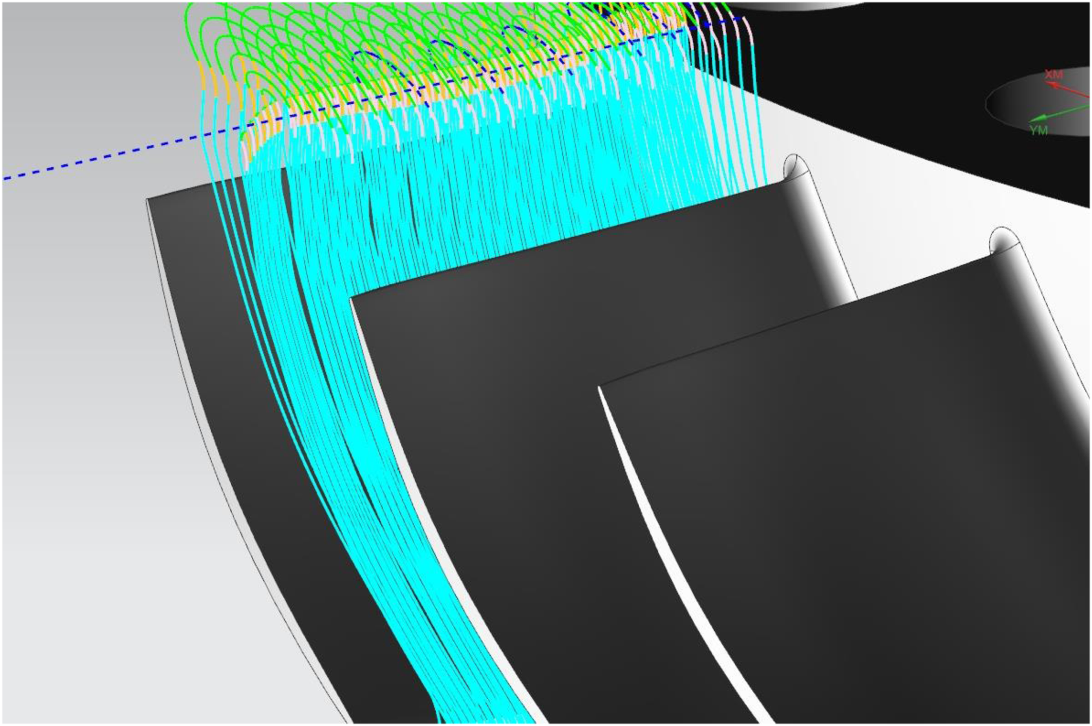
Improvement of the five-axis path
The sensory tool holder was used to conduct a five-axis machining force experiment for the tools with helix angles of 35°, 38°, and 45°. The preliminary results showed that for slot milling, the tool with a helix angle of 45° exhibited the lowest cutting force. For side milling, the tool with a helix angle of 35° exhibited the lowest cutting force. Therefore, the processing method generated by the CAM software was changed from a one-step method [combined slot milling and side milling (Figure 31)] to a two-step method. The first step involved using the tool with a helix angle of 45° for slot milling (Figure 32). The second step involved using the tool with a helix angle of 35° for side milling (Figure 33). Because of the smaller cutting force, the feed rate was increased by 20%, which resulted in an overall reduction in the machining time. The machining process is illustrated in Figures 36. The strategy in rough machining is to remove the excess material rapidly. The machined blade surface is coarse as shown in Figure 34 (a). The object of the semi-finish is to obtain machined allowance equally and a smooth surface to retain stable cutting in the stage of finish machining, as shown in Figure 34 (b). The finish machining aim is to satisfy the requirements of dimension accuracy and surface roughness. The intensity of the tool path is high and the chatter did not occur as shown in Figure 34 (c).

Slot milling tool path with the 45° helix angle.

Side milling tool path with the 35° helix angle.

Five-axis machining of blisk on the horizontal five-axis machine tool. (a) Rough machining. (b) Semi-finish machining. (c) Finish machining.
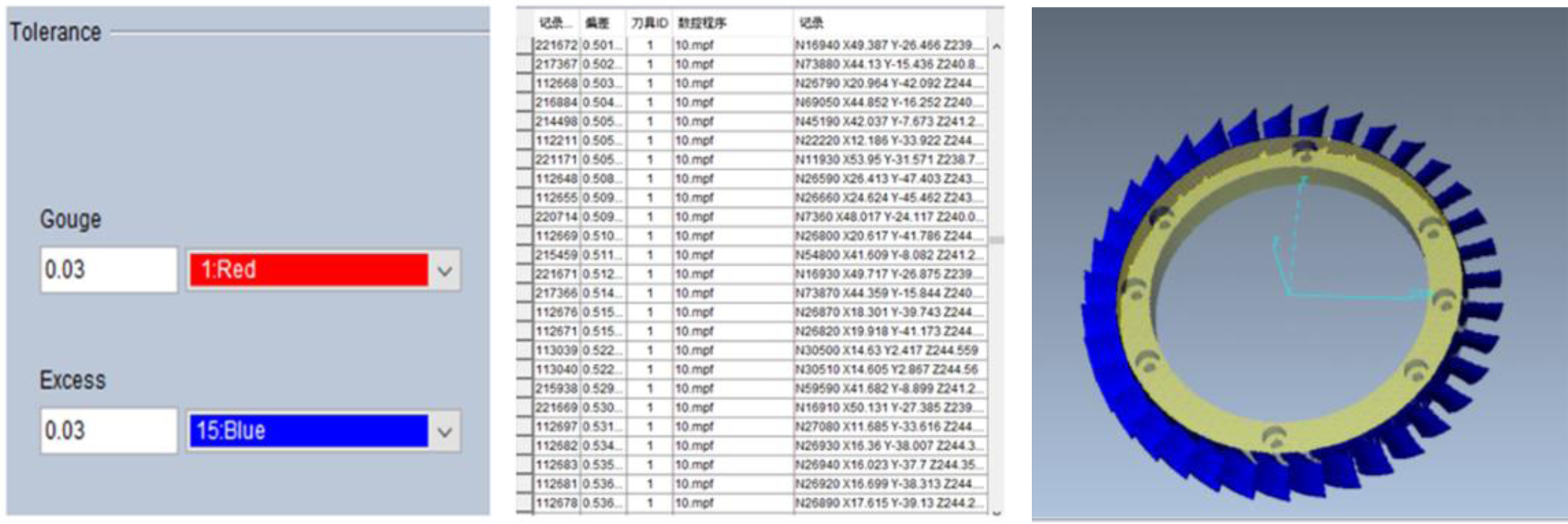
Online measurement results
The machined blisk is inspected on a five-axis machine with an online measuring system equipped with a touch-trigger probe. To confirm the dimensional accuracy of the surface of the blade, measurement is carried out after finish machining. A comparison of measured sample points and the actual profiles is shown in Figure 35. The measured results show that the maximum deviation of the machined surface is 0.073mm. The gouge tolerance and excess tolerance are both set to 0.1 mm. The maximum deviation is under tolerance.

Dimension errors of the machined blisk from online measurement after finsh machining.
Conclusion
This research is aimed at improving the development of aerospace blisks through advancements in process planning. NX10 is used to generate five-axis tool path; VERICUT is used to conduct cutting simulation; a horizontal five-axis machining tool is used to implement real cutting; and a sensory tool holder is used to evaluate cutting force and path modification to increase the machining efficiency. The main conclusions of this study are summarized:
NX10 is used to conduct process planning and five-axis cutting path arrangement. VERICUT is used to perform interference check and error analysis to ensure that machining planning fulfilled the tolerance requirement. Through the use of a sensory tool holder, cutting forces are determined and compared for three tools with different helix angles to improve the machining method. The total processing time decreased by 16.5% when increasing the feed rate by 20%. The tool engage and retract times account for 3.5% of the total processing time. A sensory tool holder is employed to monitor the real-time tool status. During the machining process, the axial force is always positive, which suggested that no tool pulling occurred. The machined surfaces are measured through the online measurement system. The maximum deviation of the machined surface is 0.073mm. It is under the setting tolerance. The proposed methodology integrates the activities of design, manufacture and quality control, thus the production process of aerospace blisk is more flexible and automatic.
Footnotes
Declaration of conflicting interests
The author(s) declared no potential conflicts of interest with respect to the research, authorship, and/or publication of this article.
Funding
The author(s) disclosed receipt of the following financial support for the research, authorship, and/or publication of this article: The authors would like to thank the support of the National Science and Technology Council, Taiwan, R.O.C. under grant MOST 109-2622-8-230-001 -TE3.
Author biographies
Jeng-Nan Lee, received his PhD in mechanical engineering from National Cheng Kung University. He is currently a professor in the Department of Mechanical Engineering at Cheng Shiu University. His research interests include the integration of CAD/CAE/CAM, multi-axis machining and toolpath optimization, additive manufacturing, rotary ultrasonic machining, intelligent manufacturing, and the evaluation of machine tool manufacturing quality
He-Lung Yeh, received his MS degree in mechatronic engineering in 2018 from Cheng Shiu University, Taiwan. His major research interests are multi-axis machining and process optimization. He is now a CAD/CAM engineer in United Orthopedic Corporation.
Ming-Jhang Shie, received his PhD in mechanical engineering from Cheng Shiu University. He is currently an assistant professor in the Department of Mechanical Engineering at Cheng Shiu University, Taiwan. His major research interests are CAD/CAM, five-axis machining technology.
Teng-Hui Chen, received his PhD in mechanical engineering from National Cheng Kung University. He is currently an assistant professor in the Department of Mechanical Engineering at Cheng Shiu University. His research interests include the integration of CAD/CAE/CAM, multi-axis machining and toolpath optimization, rotary ultrasonic machining, and the evaluation of machine tool manufacturing quality.