
Abstract
In this study, the aim was to evaluate the vibration suppression performance of the partially covered equidistant multi-ring hard coating damping treatment for the cylindrical shell structure in aviation power equipment. A continuous rectangular pulse function was presented to describe the local thickness variation of arbitrary coating proportion and arbitrary number of coating rings. A semi-analytical unified solution procedure was established by combining the rectangular pulse function, the generalized Jacobi polynomials, and the Rayleigh-Ritz method. The stiffness coefficient k = 1013 N/m2 and the truncation number N = 8 were found to be large enough to achieve an accurate and efficient solution of the vibration analysis of the shell. The modal loss factor generally increased with the increase of the coating proportion ranging from 0.0 to 1.0 for all the circumferential wave numbers. The modal loss factor increased roughly linear with the coating proportion for all the circumferential wave numbers. And the modal loss factor was increased with the circumferential wave number, and the greater the number of circumferential waves, the greater the rate of change. The increase of the ring number was not always beneficial for vibration reduction of the shell, while the modal loss factor increased roughly linear with the coating proportion. The increased ring number and coating proportion tend more to exhibit an obvious incremental damping effect under larger circumferential wave number.
Introduction
Being one kind of damping treatment with good performance in high temperature and strong corrosion environments, the hard coating has received extensive attention in vibration suppression of engine casing, blade, and blisk,1–3 which can be used for vibration reduction of the thin cylindrical shell structures with promising application prospect.4–6 However, due to the existence of appendages and the restrictions of structural weight,7–9 it is impractical to fully cover the shell surface with a coating material. Hence the study on the vibration and damping characteristics of the cylindrical shell with partial hard-coating damping treatment is of important actual significance.
In recent years, many studies have been performed on the vibration analysis of partially coated composite cylindrical shells. In terms of vibro-acoustic problems, Zou et al. 10 evaluated the effect of arbitrarily partially covered acoustic coatings on the underwater vibro-acoustic characteristics of the cylindrical shell structure, and the sound source levels of the cylindrical shell with acoustic coatings of different laying length were quantitatively discussed. Ferri et al. 11 addressed the scattering of acoustic plane waves from infinite submerged cylindrical shells partially covered with two discontinuous axial surface coating, indicating that this partial treatment had little impact on the scattered far-field pressure, but would lead to large surface pressure and velocity gradient. Laulagnet and Guyader 12 presented a vibro-acoustic model of a finite cylindrical shell partially covered with a compliant material layer to analyze the acoustic radiation in water and shell vibration, the results showed that the partial coating would exhibit considerable impact on the acoustic radiation of the shell. Xiang et al. 13 proposed a novel matrix method for the liquid-filled circular cylindrical shell partially covered with a single-ring constrained damping layer. The forced vibration analysis of the shell with different damping thickness and coverage ratios under the harmonic liquid dynamic pressure was conducted.
Moreover, in terms of partially constrained viscoelastic damping treatment, Masti and Sainsbury 14 explored the optimal damping treatment for the cylindrical shell partially covered with a double-ring standoff-layered viscoelastic coating to achieve a minimal distribution area and low added weight. It was indicated that the partial damping treatment can be more beneficial than using full coverage. Chen and Huang 15 developed an analytical model for vibration analysis of the cylindrical shell partially covered with a single-ring constrained damping layer under the Donnell-Mushtari-Vlasov assumptions, and the effects of the axial coverage length and the thickness of the damping layer on the power dissipation coefficient of the shell were discussed. The above researches lay a solid foundation for the vibration and damping analysis of the partially covered cylindrical shells. However, in the aspect of partial hard-coating damping treatment, to authors’ knowledge, only Sun et al. 16 carried out research on the optimal configuration of vibration reduction characteristics of the cantilever plate partially covered with NiCrAlCoY + YSZ hard coating based on an analytical model, while the effects of the coverage ratio, optimum location, and modal loss factor of the hard coating were discussed.
As seen from the literature review, the vibration of a cylindrical shell partially covered with circumferential hard coating has not been studied, especially with the multi-ring hard coating. For the regular arrangement of the appendages (such as the rivets or pipelines) along the axial direction of the shell in aviation power equipment, the scheme of equidistant multi-ring hard coating damping treatment would be a targeted solution with high practical values. As the basic structures in practical engineering, the vibration characteristics of the cylindrical shells have been fully and systematically investigated in many studies,17–23 but there is still a lack of systematic and methodic research on the cylindrical shell partially coated with equidistant multi-ring hard coating for vibration reduction. Therefore, the study on vibration suppression performance of the partially covered equidistant multi-ring hard coating damping treatment for the cylindrical shell structure in aviation power equipment is carried out in this paper.
Methods
Model description
The cylindrical shell partially covered with an equidistant multi-ring hard coating with the clamped boundary condition is investigated in this work. The geometry of the shell in an orthogonal curvilinear coordinate system (x, θ, z) is shown in Figure 1. h,

Geometry of the cylindrical shell partially covered with equidistant multi-ring hard coating.
Unified thickness formula for an arbitrary number of coating rings
To achieve a unified semi-analytical solution for the free vibration problem of the cylindrical shell partially covered with equidistant multi-ring hard coating, a specially designed continuous rectangular pulse function is presented to describe the local thickness variation under arbitrary coating proportion and an arbitrary number of coating rings, defined by

where


where

Plot of the coating thickness under different ring number and coating proportion.
Admissible displacements
The axial, circumferential and radial displacements u, v, and w at the middle surface of the multi-ring hard-coating cylindrical shell can be expressed by24,25

where

where

where

The Jacobi polynomials with
Energy expressions
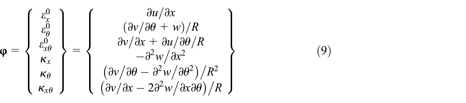
Based on Love’s first approximation theory, 28 the strains at any point of the partial covered thin cylindrical shell with h/L ≪ 1 can be defined as:

where
Due to the unified treatment for the thickness of the multi-ring hard coating, the radius of the middle surface

where

where

where

Here

To facilitate subsequent formula derivation, the so-called extensional, coupling and bending stiffness

where


Similarly, the potential energy introduced by the artificial springs applied to the bottom end of the shell can be expressed as the following form

Unified solution via Rayleigh-Ritz procedure
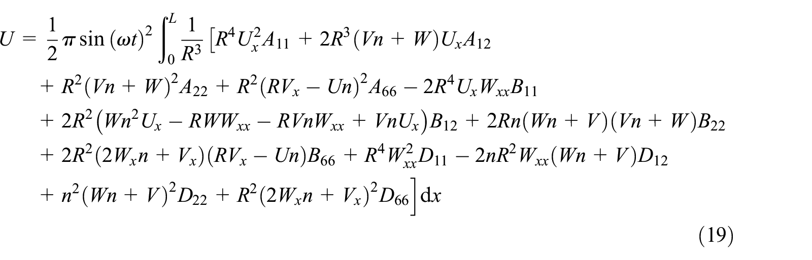
To determine the weighting coefficients and the displacement components in equations (4) and (5), the Rayleigh-Ritz method is employed to derive the motion equations of the shell. Substituting the detailed expressions of u, v, and w in equation (4) into equations (16) and (17), yields

where

The potential energy introduced by the clamped boundary with artificial springs is given by

Based on the above strain energy, kinetic energy, and potential energy, the Lagrangian energy function can be defined as the following

where the superscript “max” refers to the maximum value. By differentiating the above Lagrangian energy function with respect to

where
Similarly,


The detailed expressions of
By solving the eigenvalue problem in equation (24), the natural frequencies and the corresponding eigenvectors of the shell can be conveniently acquired. The natural frequency and the standardized eigenvector with respect to the circumferential wave number n are calculated, respectively, by


Simultaneously, the modal loss factor of the shell for the certain circumferential wave number n can be obtained by using the real and imaginary part of the eigenvalues, 24 expressed by

Results and discussion
Convergence analysis
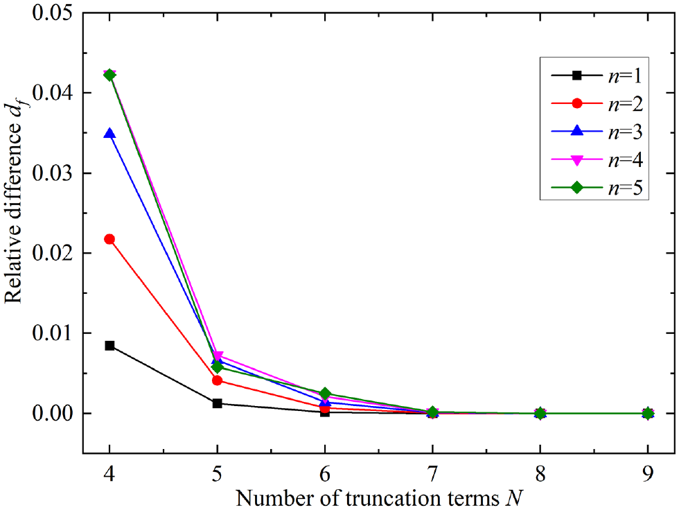
As the truncation terms of the Jacobi-type admissible function and the stiffness of the introduced artificial springs are directly related to the accuracy and efficiency of the semi-analytical model, the convergence of the natural frequency versus the truncation number N and the stiffness coefficient k should be carefully examined. Although the truncation terms of orthogonal polynomials for clamped-free shells have been investigated in many studies,29,30 the truncation number for achieving accurate results would be also slightly different due to the model differences including the geometric dimension, nonlinear factors, types of orthogonal polynomials, etc. Directly using the values provided in the above literature may cause certain accuracy problems. Moreover, since the general coating thickness
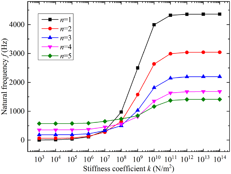
Convergence of the natural frequency versus the stiffness coefficient k.
Convergence of the natural frequency versus the truncation number N.
From Figure 3 we can find that the natural frequencies increase in a nonlinear manner with the increasing stiffness coefficient ranging from 103 to 1014 N/m2. Especially, in the range of 106–1011 N/m2, the natural frequencies increase the fastest and then gradually converge to the stable values when the stiffness coefficient k is greater than or equal to 1013 N/m2. The results indicate that the stiffness coefficient k = 1013 N/m2 is large enough to simulate the clamped boundary condition of the shell. It is worth noting that the stiffness coefficient k = 1013 N/m2 is only valid for the present model since the value of the stiffness coefficient for the clamped boundary condition also depends on the stiffness of the shell and other factors. Additionally, to evaluate the influence of the number of truncation terms of the admissible function on the natural frequency, the relative difference
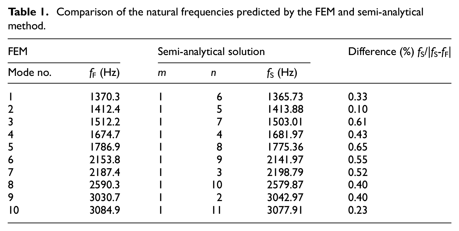
Model validation
Since the research on free vibration of the thin cylindrical shell partially covered with equidistant multi-ring hard coating is seldom reported in existing literature, the natural frequencies and corresponding modal shapes of the shell calculated by the present semi-analytical method are compared with the numerical results from the finite element method (FEM) based on ABAQUS v6.13 for validation. The partially covered hard-coating cylindrical shell is modeled with a 4-node S4R shell element. The total number of nodes and elements are 86,524 and 85,632, respectively. In the FEM model, the cylindrical shell is split into eight equally-sized circular rings along the axial direction, while the composite and single-layer shell sections are respectively employed to simulate the coated and uncoated regions of the cylindrical shell partially covered by equidistant four-ring hard coating, as shown in Figure 5.

FEM modeling of the cylindrical shell partially covered by equidistant four-ring hard coating.
The adopted geometric parameters and material property of the shell are presented as below in detail:
Comparison of the natural frequencies predicted by the FEM and semi-analytical method.

Comparison of the mode shapes predicted by the FEM and present semi-analytical method.
Effect analysis of the ring number
As a main coating parameter, the ring number would have a non-negligible impact on the vibration of the partially covered cylindrical shell. Therefore, further analysis should be carried out to better understand the effect of the ring number on the damping performance of this partial multi-ring hard coating treatment. For different circumferential wave numbers, the effect of the ring number of hard coating with the modal loss factor as research object is investigated, as shown in Figure 7.

Effect of the ring number on the modal loss factor under different circumferential wave numbers.
From Figure 7 we can see that the modal loss factor generally decreases with the increase of the ring number ranging from 1 to 20 when the circumferential wave number
Furthermore, the effect of the ring number on the modal loss factor of each circumferential wave number is more clearly presented in Figure 8.

Effect of the ring number on the modal loss factor of each circumferential wave number.
As can be seen from Figure 8, the variation of the ring number has little effect on the modal loss factor of the circumferential wave number n = 1. Meanwhile, the modal loss factor is decreased slightly by increasing the ring number when the circumferential wave number n = 2, 3, and 4. When the circumferential wave number
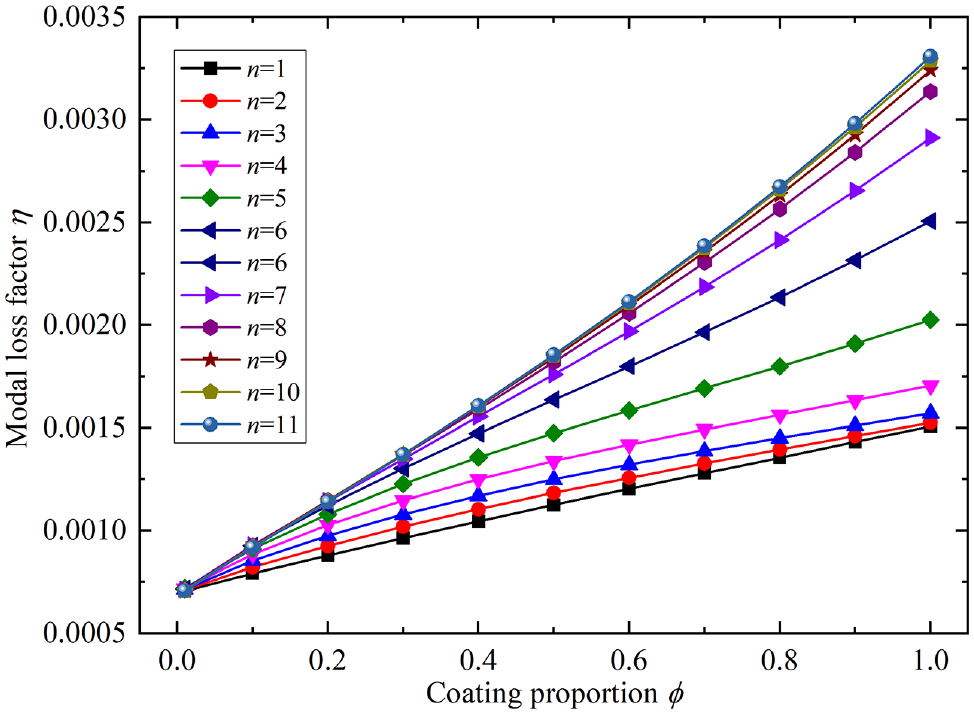
Effect analysis of the coating proportion
Similar to the ring number, as an important parameter of the partial multi-ring hard coating damping treatment, the coating proportion also has a direct influence on the modal loss factor of the shell. Hence the effect of the coating proportion on the modal loss factor under different circumferential wave numbers is investigated, as shown in Figure 9. From Figure 9, it can be found that the modal loss factor generally increases with the increase of the coating proportion ranging from 0.0 to 1.0 for all the circumferential wave numbers. When the coating proportion is relatively small, the impacts of the coating proportion on the modal loss factors under different circumferential wave numbers are basically the same. With the increase of the coating proportion, a larger circumferential wave number tends to have a greater modal loss factor, and this phenomenon demonstrates that the increased coating proportion is more beneficial to suppress the vibration of the thin cylindrical shell with a large circumferential wave number.

Effect of the coating proportion on the modal loss factor under different circumferential wave numbers.
Moreover, the effect of the coating proportion on the modal loss factor of each circumferential wave number is illustrated in Figure 10. It can be seen more directly and clearly that the modal loss factor increases roughly linear with the coating proportion for all the circumferential wave numbers. Meanwhile, the results also indicate that the modal loss factor is increased with the circumferential wave number, and the greater the number of circumferential waves, the greater the rate of change. Compared with the ring number, the effect of the coating proportion on the modal loss factor is relatively simple and the corresponding law of influence is only monotonous increasing. However, due to the existence of appendages (such as the rivets or pipelines) and the restrictions of structural weight, there often exists a limit for the coating proportion in practice. Hence the maximum coating proportion should be determined according to the actual working conditions of the shell.
Effect of the coating proportion on the modal loss factor of each circumferential wave number.
Conclusions
In this paper, a continuous rectangular pulse function designed for arbitrary equidistant partial multi-ring hard coating treatment of the cylindrical shell is presented. By combining the rectangular pulse function, the generalized Jacobi polynomials and the Rayleigh-Ritz method, a unified Jacobi-Ritz semi-analytical solution procedure is established for the free vibration and damping analysis of the shell. The convergence analysis and model validation demonstrate the feasibility, accuracy, and efficiency of the developed semi-analytical formula. The effects of the ring number and coating proportion on the vibration and damping characteristics are studied. The following conclusions are obtained:
The stiffness coefficient k = 1013 N/m2 and the truncation number N = 8 are large enough to simulate the clamped boundary condition and to achieve the accurate and efficient solution of the vibration of the shell, respectively.
The increase of the ring number is not always beneficial for vibration reduction of the shell, and the law of influence mainly depends on the circumferential wave number. The increased ring number tends more to exhibit an obvious incremental effect under a larger circumferential wave number. In particular, the ring number
The modal loss factor increases roughly linear with the coating proportion ranging from 0.0 to 1.0 for all the circumferential wave numbers, and the greater the circumferential wave number, the greater the modal loss factor and its rate of change. The increased coating proportion is more beneficial to suppress the vibration of the thin cylindrical shell with a large circumferential wave number, the results of which may be served as a theoretical basis for engineering application.
Footnotes
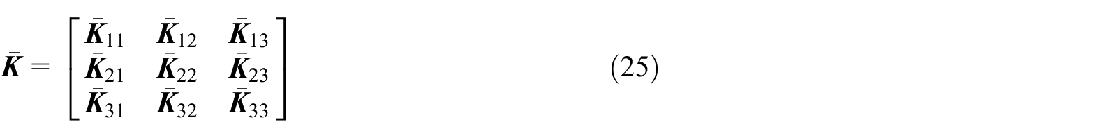
Appendix A: Detailed expressions of the complex-valued stiffness matrix K ¯
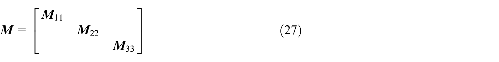
Appendix B: Detailed expressions of the mass matrix M
The detailed expressions of the mass matrixes in equaiton (27) are given as follows
Appendix C: Detailed expressions of the spring stiffnessmatrix K b
The detailed expressions of the stiffness matrixes of the clamped boundary with artificial springs in equation (26) are given as follows
Declaration of conflicting interests
The author(s) declared no potential conflicts of interest with respect to the research, authorship, and/or publication of this article.
Funding
The author(s) disclosed receipt of the following financial support for the research, authorship, and/or publication of this article: This project is supported by Youth Foundation of Educational Department of Liaoning Province, China (Grant No.2020LNQN16), the Youth Foundation of University of Science and Technology Liaoning, China (No.2019QN06).