
Abstract
Chip morphology is one of the evaluation indexes of cutting performance of cutting tools, and chip forming process has a direct and important influence on chip morphology. High-strength steel 40CrMnMo is one of typical oil country tubular goods (OCTG) and difficult-to-cut materials, and its chip morphology represents the machining quality of OCTG. The chip forming process of a new independent-developed microgroove turning tool for turning oil country tubular goods 40CrMnMo is researched, combining machining experiments with theoretical analysis. Research results show that with the increase of cutting speed, the initial radius of curvature of the chip fluctuates slightly, but the overall trend is upward. However, the ultimate radius of curvature decreases and the chip’s radius ratio also decreases. The relative ideal chip can be obtained if the proper cutting velocity and feed rate are given. Chip morphology results from the comprehensive effect of the two processes: The fracture and separation process of the workpiece during passing through the shear deformation zone and the process of curling and breaking away of the chip after passing through the rake face of the tool. The research results have a certain guiding significance for controlling the cutting process of machining the other material with similar performance.
Introduction
Chip morphology is one of the evaluation indexes of cutting performance of cutting tools, and the chip forming process has a direct and important influence on chip morphology. Palmai and Csernak 1 describing the chip formation in the turning process by proposing a thermo-mechanical model, and results showed that the theoretical model mentioned above could express the chip formation process well. Khoshdarregi and Altintas 2 focused on the cross-section of the chip in the thread machining process and found that the chip shape and turning load distribution can be expressed and predicted by the generalized mechanical model. Aramcharoen 3 investigated the effect of cryogenic cooling on the chip forming process in a high-speed cutting process and found that different chip formations occurred under different cutting conditions. Bhuiyan et al. 4 investigated chip formation under different cutting conditions in the turning process, and researches proved that plastic deformation had a significant effect on chip formation. Chiappini et al. 5 investigated the stability in the cutting process completely neglecting the chip formation under variable spindle speed. Galatolo and Fanteria 6 and Bache et al. 7 were concerned with the effect of cutting conditions on the fracture properties of workpiece materials to reveal the relationship between the fatigue crack growth and the chip formation. Yi et al. 8 studied the effects of material response on the chip forming process in the processing of Inconel718, and found that the material responses of the tool-chip interface under cutting speeds are different. Baizeau et al. 9 put forward a novel approach to analyze the chip forming process and exposed the effect of the cutting velocity and the unprocessed chip thickness on force variety and the chip’s production frequency. Buchkremer et al.10,11 put forward a novel FEM method for describing the relation between the 3D chip shape and the triaxial stress distribution in the chip’s breakage position. It was proved that the large stress where the chip breaks mainly happened at the time when the chip bent. Maruda et al.12,13 were concerned with the effect of the cooling approach on the factors given in the chip forming process and the chip geometry. Researches showed that the short spiral-style chip or quite loose chip can be easier to remove from the cutting region when the cooling approach is MQCL. Nobel et al. 14 dealt with a test to research the effect of the chip forming process on the machining process and analyzed the chip shape to achieve a reasonable chip breaking mechanism. Zhang et al. 15 presented a novel method to research chip segmentation. It confirmed that cutting velocity and unprocessed chip thickness have important effects on chip formation.
Investigations on the forming process of chip above chiefly focused on the chip morphology, the effect of the chip morphology on the tool wear, the method of chip breaking and chip characteristics.16–18 And researches about the chip forming process in the process of a new self-developed turning tool, especially for machining oil country tubular goods (OCTG) were rather rare.
The aim of this research is to the investigate chip forming process and its evaluation method in the process of a new independent-developed microgroove turning tool machining oil country tubular goods, 40CrMnMo (one of typical oil country tubular goods and difficult-to-cut materials, abbreviated OCTG), and the corresponding chip shape and morphology are evaluated by the analysis of the effect of different cutting parameters on the initial curvature radius of the chip. And the model of the chip forming process and the mechanical model of chip movement are established to help to explain the chip forming mechanism and evaluate its morphology in this work.
Materials and methods
Cutting experimental design
The comparative experiments have been completed on the lathe CW6163C, aimed to research the chip forming process of the independent-developed microgroove turning tool and the ordinary turning tool with the same cemented carbide material, and an appropriate cutting experimental platform referred to the one established in the research provided by Jiang et al.19–21 is built as shown in Figure 1. The cutting conditions are as follows: the cutting velocity

Cutting experimental platform: (a) ordinary tool and (b) microgroove tool.
Property parameters of material.

Geometric angle of the tool.

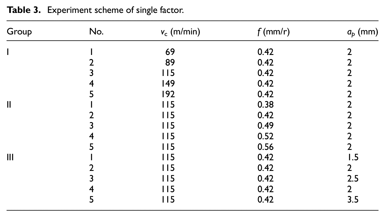
Overall considering the experimental purpose, requirements, cutting conditions, and experimental effectiveness, the experiment scheme of single factor with cutting parameters as impact factors is established as shown in Table 3.
Experiment scheme of single factor.
Sample preparation
Based on the completed cutting experiment above, the chips of each group are sampled and observed using a metallographic microscope. Considering the requirements of the experiment, the reliability of the data and so on, three pieces of the chip of each test are sampled and a valid sample is elected from them by observation and screening. Prepared samples are shown in Figure 2 respectively.

Chip samples of single factor.
Theoretical method
Generally, the study of chips is based on the assumption that the natural chip flows steadily. That is, assuming that the flow direction and the curl direction of the chip do not change with time. For a point on the tool-chip separation line, its moving trajectory is a geometric curve. According to differential geometry, curvature and torsion can be used to describe the shape feature of a micro-segment. Curvature and torsion both are constants in steady flow status, and such a curve is a cylindrical spiral line. Lee et al. 22 indicated that in actual machining, in a very short period of time, that is, in the micro section, the state can be considered stable. So that the micro-segment of the chip is spiral shape. Vasumathy and Meena 23 and Amini and Kazemiyoun 24 also divided the chip into a lot of micro-segments to study the chip flow on the tool-chip interface. Here, the chip forming process which consists of spiral micro-segments formed under steady flow conditions is investigated.
The mechanical model of chip movement is established according to the characteristics of the chip movement here as shown in Figure 3. On the tool-chip separation line, the velocity of each particle is parallel to the rake face, and here is no velocity component in the direction of the Z axis, so chips don’t move around Y axis which means


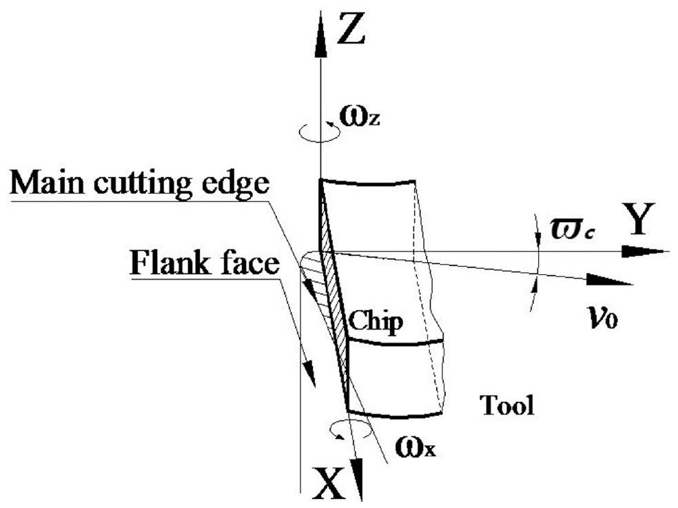
Mechanical model of chip movement.
Thus, the angular velocity

The simplified model of the spiral chip forming process of the independent-developed microgroove turning tool is established and shown in Figure 4 referred to the mathematical model of tool-chip developed by Jamshidi and Nategh
25
and Biermann et al.
26
The chip with initial radius
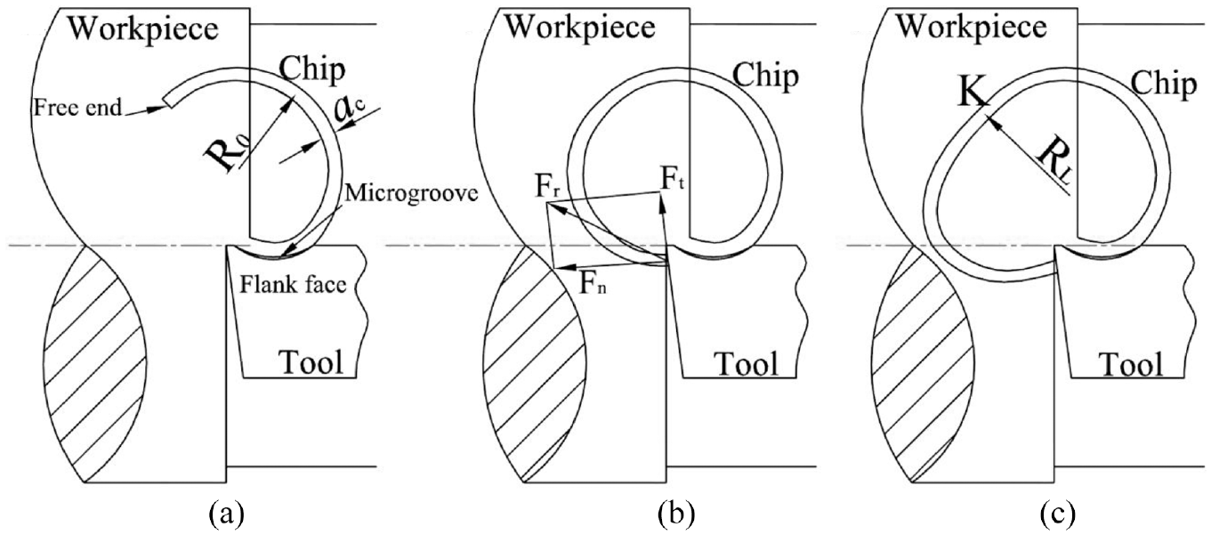
Chip forming process (a) Early stage, (b) Middle stage, (c) Late stage.
According to the metal cutting principles, the chip breaking conditions established shown in equation (4):


Where
According to the chip breaking condition provided by Joshi and Singh,
29
important factors affecting chip breakage include: the chip section shape, the chip thickness

A lot of experiments show that the formed chip is “good chip” when
Experimental results
The samples were observed at equal multiples, and the chip’s initial radius of curvature

Effect of cutting parameters on radius of curvature of chip: (a) Effect of cutting speed on curling radius, (b) Effect of cutting speed on radius ratio, (c) Effect of feed rate on curling radius, (d) Effect of feed rate on radius ratio, (e) Effect of cutting depth on curling radius, (f) Effect of cutting depth on radius ratio.
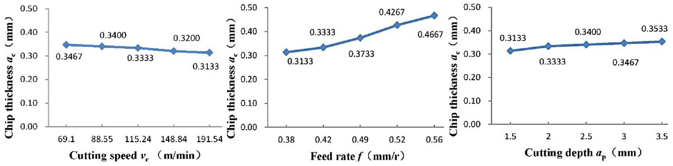
Effect of cutting parameters on chip thickness.
As shown in Figure 5(a) and (b), with the increase of cutting speed, the initial radius of curvature of chip
The fracture morphologies are shown in Figure 7. Figure 8(a) and (b) show that the forming process of the chips produced by the ordinary turning tool and the independent-developed microgroove turning tool from the perspective of machining simulation under the same cutting conditions with the cutting experiments. The colors of Figure 8 present the temperature distribution, which is not the focus of the simulation here, and the purpose of the machining simulation is to show and verify the forming process of chips produced by the two turning tools.

Contrast of chip morphology and forming process cut by different turning tools in experiments: (a) ordinary turning tool and (b) microgroove turning tool.

Contrast of chip morphology and forming process cut by different turning tools in simulations: (a) ordinary turning tool and (b) microgroove turning tool.
The analysis above objectively and reasonably reveals the forming mechanism of the chip produced by the independent-developed microgroove turning tool about the process of the workpiece material fracture and separation when flowing through the shear zone. Then, the process of the chip curling and breaking away after it passing through the rake face of the tool is analyzed. Comparison between the chip shape of the ordinary turning tool and the one of the independent-developed microgroove turning tool is shown in Figure 9 and effects of different parameters on the chip shape and morphology of the microgroove turning tool are presented in Figure 10.

Comparison of chip shape of different turning tools: (a) chips of the ordinary turning tool and (b) chips of the independent-developed turning tool.
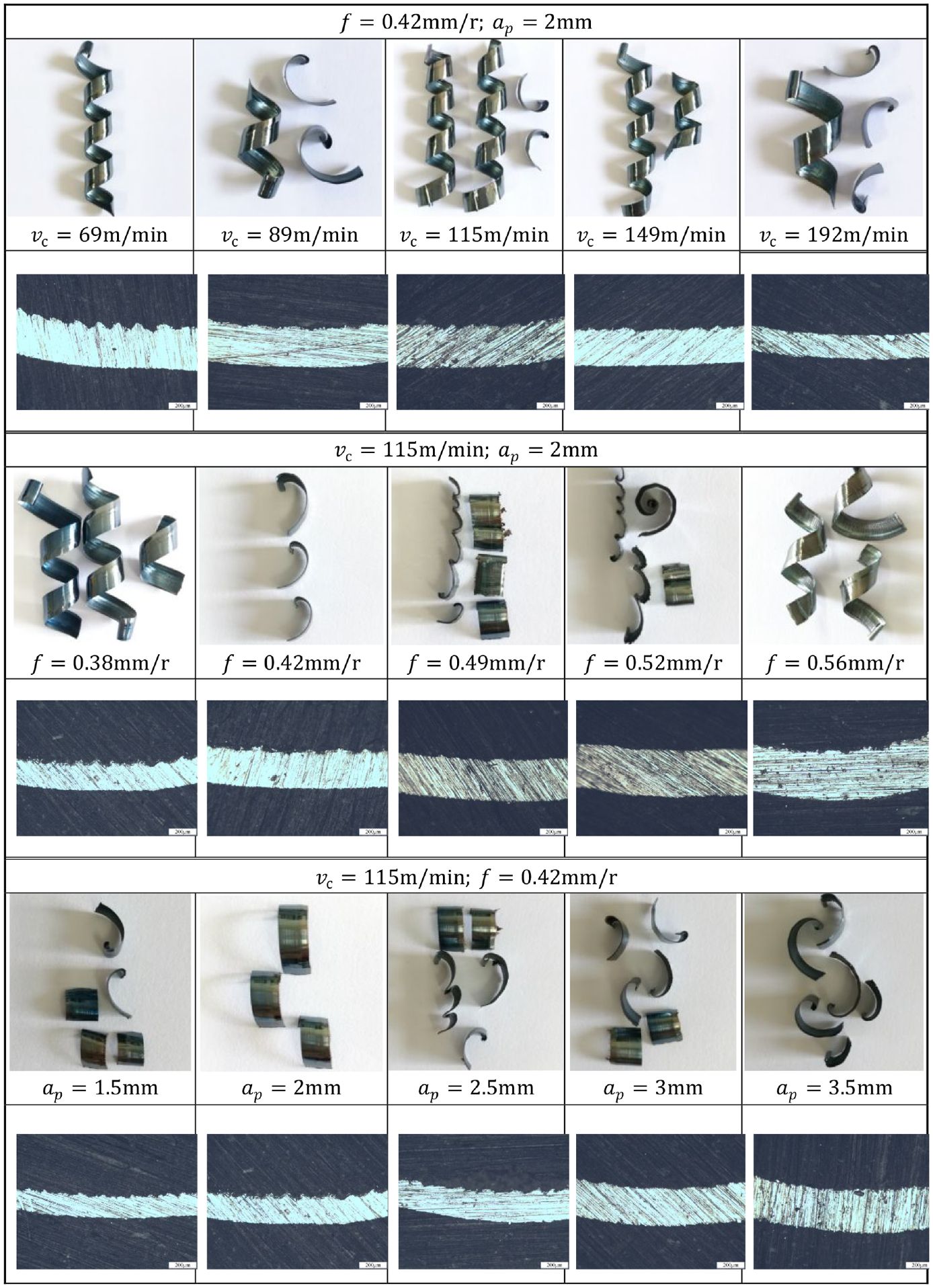
Effect of different parameters on the chip shape and morphology of microgroove turning tool.
It can be seen from Figure 10 that with the growth of cutting velocity, the chip thickness gradually decreases, while the curling radius increases gradually, and the chip shape gradually changes from medium length spiral to short spiral, and finally becomes a planar spiral. With the growth of feed rate, the chip thickness grows gradually, and the curling radius decreases firstly and then increases gradually. The chip shape changes from medium-length spiral to curling broken. After the feed rate becomes more than
Analysis and discussion
Evaluation of chips
Combined with the results shown in Figure 5(a) and (b), with the growth of cutting velocity
The forming process of chips
The chip morphology is mainly the result of the comprehensive action of two processes: The fracture and separation process of the workpiece during flowing through the shear deformation zone and the process of curling and breaking away of the chip after it passing through the rake face of the tool. Firstly, the forming process of the workpiece materials during passing through the shear deformation zone is analyzed which has been studied deeply in the previously completed research. The mechanical properties of the workpiece materials when flowing through the shear deformation zone are the results of the comprehensive function of the strain hardening effect of materials, the size effect of the shear zone, the strain rate strengthening effect, and the thermal softening effect. And these factors restrict and promote each other. Thepsonthi and Ozel 30 and Varghese et al. 31 found that with the continuous feeding of a turning tool, the new material will continue to enter the shear zone to push the front materials flowing through the shear zone before out of this zone. So when this part of materials leaves the neutral shear plane of the shear zone here, shear fracture and separation of the materials happen, then the chip forms.
Figure 7(a) and (b) show that the chip’s free surface produced by the ordinary turning tool presents serration, and the one produced by the microgroove turning tool doesn’t present obvious serration. It can be seen from Figure 8 that the chip flowing through the shear zone and produced by the ordinary turning tool has a very small curvature, and the one produced by the microgroove turning tool has a large curvature. Lots of researches showed that the generation of the serrated chip resulted from the thermoplastic shear instability of materials in the shear deformation zone, while the shear instability was caused by the phenomenon resulting from the thermal softening effect of the shear deformation zone that the decrement of the flow stress was greater than the increase of the flow stress, combined with the research conclusions from Kone et al. 32 The essence of the thermal softening effect of materials is the dynamic recovery and recrystallization of the material after its temperature reaches the recrystallization temperature, which leads to the reduction of the flow stress and the reduction of strength and hardness of the material. It can be indicated that the temperature of the shear deformation zone in the machining process of the independent-developed microgroove turning tool is lower than the one of the ordinary turning tool. The chip produced by the ordinary turning tool is shown in Figure 7(a), with the continuous going of the cutting process, the shear slip occurs continuously, which results in the thermoplastic shear instability. Thermoplastic shear instability further improves the strain rate of materials. At higher strain rates, the heat conductivity process of materials lags relatively. That is, the heat source can not transfer heat to the surrounding material timely so that the plastic deformation is concentrated in a local range near the tool tip, and a concentrated shear band is formed in the shear deformation zone. The material strain in the concentrated shear band is greater than the one in other regions, which results in dislocation slip of the workpiece material occurs along the concentrated shear band formed by shear instability, and that further aggravates the thermoplastic shear deformation. The microscopic accumulation of shear slip can lead to the local fracture of materials. With the continuous movement of the turning tool along the feed direction, the chip free surface presents serration. The decrement of the flow stress resulted from the thermal softening effect of materials in the shear deformation zone is not sufficient to compensate for its increase resulted from the strain hardening. Therefore, the deformed material’s strength which is about to flow out of the shear zone is greater than the one of the materials which is about to enter the shear zone. As the cutting process proceeds, the deformed material moves with the tool along the feed direction and departs from the shear zone relatively continuously and smoothly, so the chip’s free surface does not exhibit a pronounced serration.
The chip produced by the ordinary turning tool is continuous disordered scrip-type, and the chip produced by the microgroove turning tool is short spiral and planar spiral as shown in Figure 9. For the independent-developed microgroove turning tool, the chip is subjected to the counterforce from the inner wall of the microgroove when passing through the shear deformation zone. The root of the chip in the plastic flow state has certain adaptability to the external force or the external moment, and the stress distribution of the region can change. Then the root of the chip close to the rake face is subjected to tensile stress, and the free face of the chip is subjected to compressive stress. The shape of the stagnant layer between the tool and the chip can vary. In the direction of the chip thickness, the outflow velocity of the bottom material is greater than the one of the free surface. In the direction of the chip width, the outflow velocity of the chip material near the tool tip is greater than the one of the free surface side. The results of the comprehensive function are: the chip curls upward and positively sideward as shown in Figure 4(a). With the progress of cutting, the chip continues to grow and accumulate until its free end hits the flank face and is subjected to the counterforce
Conclusions
According to the researches in this paper, the main conclusions can be summarized as follows:
The chip morphology is mainly the result of the comprehensive action of two processes: The fracture and separation process of the workpiece material during passing through the shear deformation zone and the process of curling and breaking away of the chip after it passing through the rake face of the tool.
It is also found that from experimental researches above that the larger the chip’s ultimate radius of curvature is, the stronger the contact between the chip free end and the flank face is, the more difficult it is to slip away from the flank face for the chip. The more stable the counterforce the free end is subjected to, thus the more easily the chip breaks, and conversely more difficult. The varieties of cutting speed and feed rate have an obvious effect on the chip forming process, and the effect of cutting depth on the chip geometry is mainly reflected in the chip width, and it has little influence on the chip thickness and the curling radius. So, as long as the cutting velocity and the feed rate are appropriate, the ideal chip of the independent-developed microgroove turning tool can be obtained.
The chip forming mechanism of the independent-developed microgroove turning tool is obviously distinct from existing researches such as a cutting tool with chip-curling groove, a turning tool with a chip breaker, and a tool with friction-reducing grooves. It mainly affects the chip forming process from the two aspects below: on hand is the establishment of the new tool-chip contact state instead of the original tool-chip contact state, which leads to the movement of tool-chip separation point and the rotation clockwise of the resultant action line of the mechanical model of the microgroove turning tool. The other hand is the full tool-chip contact of the independent-developed microgroove turning tool, which causes less stress acting on the unit area of the rake face and the appropriate longer time for the process of the chip curling and breaking away after passing through the rake face, avoiding broken-granular chip and disorder-scrip chip, and obtaining the ideal chip.
Footnotes
Declaration of conflicting interests
The author(s) declared no potential conflicts of interest with respect to the research, authorship, and/or publication of this article.
Funding
The author(s) disclosed receipt of the following financial support for the research, authorship, and/or publication of this article: This work is financially supported by National Natural Science Foundation of China (52005118), Young Scientific Technical Talents Development Fund of Guizhou Province (QJHKY Character [2018]248), and High-level Talents Research Initiation Fund of Guizhou Institute of Technology (2019066).