
Abstract
The permissible contact stress for the rolling bearing made of the through hardened bearing steel has been established based on experience, while there is no definite value or calculating formula of the permissible contact stress for the slewing bearings which are hardened only on the raceway surface yet. To determine the permissible contact stress of the case hardened raceway of roller slewing bearing, finite element analysis for the contact elasto-plastic characteristics between the loaded roller and the case hardened raceway was performed, and the contact plastic deformations corresponding to different roller diameter, roller load, and case depth were obtained. The contact stress produced by the roller load was calculated by using Hertz contact theory. Based on the nonlinear regression analysis between the input parameters and the output plastic deformations of the model, the relation equation between the contact plastic deformation and the roller diameter, contact stress, case depth was established. The formula for calculating the permissible contact stress of the case hardened raceway was obtained according to the regression equation further. The permissible contact stresses calculated by using the obtained formula show that the permissible contact stress of the case hardened raceway depends mainly on the case depth. Loaded compression tests between the roller and the case hardened specimens were conducted to verify the validity of the established calculation method for the permissible contact stress of the case hardened raceway. Permissible contact stress decreases slightly with the increase of the roller diameter and increases with the increase of the case depth significantly. As the case depth reaches 6 mm, the maximum permissible contact stress is 3758 MPa. As the case depth reaches 7 mm, the maximum permissible contact stress of the case hardened raceway is 3889 MPa.
Introduction
Slewing bearings are widely used in wind turbine, shield tunneling machine, tower crane, bucket wheel stacker and other mechanical equipment. Significantly different from the traditional rolling bearings which are made of bearing steel and hardened fully, slewing bearings are manufactured by alloy structural steel and hardened only on their raceway’s surfaces for improving load carrying capacity. The rolling elements of slewing bearings can be rollers or balls. Existing research work mainly aims at the ball slewing bearings.1–4 Roller slewing bearings provide a line contact between the roller and the raceway, whose load carrying capacity are higher than ball slewing bearings with point contact between the ball and the raceway. Slewing bearings usually work under the condition of low speed and heavy load, the static load carrying capacity is a technical indicator for determining whether the selected slewing bearing can withstand the given extreme static load. Accurate calculations of the load carrying capacity of the roller slewing bearing are attracting more and more attention from the researchers.
Aguirrebeitia et al. 5 built the geometrical interference model of the three-row roller slewing bearing under the axial load and the tilting moment. The limiting values of the axial load and the tilting moment combinations that result in static failure of the raceway by the most loaded roller were calculated. The calculated limiting values were used to plot the acceptance curve in the load space for selecting the appropriate three-row roller slewing bearing quickly. Ludwik 6 calculated the load-deformation characteristics between the roller and the raceway by finite element method for the purpose of substituting the rollers with truss elements as building the finite element model of the entire three-row roller slewing bearing. Göncz et al. 7 analyzed the internal roller contact force distribution in a three-row roller slewing bearing by using the simplified finite element model. Numerically determined contact stresses were served for analyzing the bearing’s service by using the stress-life approach.
In the above research work, the raceways are regarded as homogeneous material as calculating the load carrying capacity of the three-row roller slewing bearing. The influence of the case hardened layer on the stress distribution and the raceway life was not considered. Göncz et al. 8 applied Tresca criterion, Misses criterion, and permanent contact deformation criterion to determine the permissible roller load of the case hardened raceway respectively. Glodež et al. 9 calculated the subsurface stresses and strains of the case hardened raceway by using the finite element model. The case hardened raceway was modeled with three layers, and each layer was given different elasto-plastic material properties in the model. He et al. 10 presented a finite element model of a three-row roller slewing bearing by replacing the solid rollers with the non-linear spring elements. Göncz et al. 11 constructed a finite element model of the roller-raceway contact, the model of the raceway was composed of three discrete layers for which the corresponding elasto-plastic material properties were defined. Influences of the roller geometry, the roller tilt angle and the raceway case depth on the permissible static roller load were analyzed. Kunc et al. 12 presented an elasto-plastic constitutive model of the case hardened raceway which includes the mechanics of material damage with the isotropic and kinematic hardening/softening. Zwirlein and Wieland 13 analyzed the subsurface Mises equivalent stress distribution of the raceway by using the distortion energy hypothesis. They advised to use the tensile strength of the core material as the guide value for the determination of the permissible Mises equivalent stress under static loading condition, and use the cyclic yield strength of the core material for the determination of the permissible Mises equivalent stress under dynamic loading condition. Harris et al. 14 proposed a criterion for determining the required case depth that the subsurface shear stress at the depth where the core hardness starts should not exceed the permissible yield shear and the permissible fatigue shear stresses of the core material. Lai et al. 15 studied the plastic deformation and the subsurface stress of an induction hardened surface by elasto-plastic finite element analyzing. They proposed a calculation method for the static capacity of induction hardened rings based on the considerations of the plastic indentation and the subsurface damage.
Hertz contact stress corresponding to the plastic deformation of 0.0001of the rolling element diameter is used as the permissible stress of the raceway. ISO standard 16 provides the permissible contact stress for the rolling bearing made of the through hardened bearing steel. There is not any definite value or calculating formula of the permissible contact stress for the slewing bearings which are hardened only on the raceway surface yet. There exits some researches about line contact probolems.17–20 These researches mainly focus on the elastic contact of the materials with uniform parameters, while the present work focuses on elasto-plastic contact of the materials with non-uniform parameters along the depth. The intention of this paper is to establish a method for determining the permissible contact stress of the case hardened raceway of the roller slewing bearing.
Plastic contact deformation principle of the raceway
As the loaded roller acts on the raceway surface, line contact appears between the roller and the raceway surface. Based on Hertz contact theory, the contact pressure distribution on the raceway surface is given by 21

where
From the above formula, the maximum contact stress at the center of the contact width can be obtained as

The contact semiwidth which depends on the contact load and the contact geometry parameters can be expressed as

where
The maximum principal shear stress which acts on a 45° plane appears at a certain depth beneath the contact width center of the raceway surface. The principal shear stress beneath the contact width center can be expressed along the depth direction as 22

where
The distribution curve of the principal shear stress along the depth direction can be calculated by using formula (4), as the heavy dotted line shown in Figure 1. According to the hardness distribution along the depth direction, the case hardened raceway can be divided into case layer, transition layer, and the core organization. Hardness difference along the depth direction causes the material to have different yield stress values at different depth. The distribution curve of the material yield stress along the depth direction is represented by the heavy solid line as shown in Figure 1. As the principal shear stress at a certain depth beneath the contact width center of the raceway surface exceeds the yield stress of the material, the material will yield. As shown in Figure 1, in the depth region corresponding to the shaded area where the shear stress exceeds the yield stress, material yielding will occur. The yield appeared beneath the raceway surface will cause the redistribution of the stresses, which could cause the extension of the yield area. As the yield extends to the raceway surface, it finally appears as the plastic contact deformation of the raceway surface.

Yield principle of the case hardened raceway.
Analysis of plastic contact deformation of the raceway
The elasto-plastic properties of the case hardened raceway are much more complex than the elasto-plastic properties of the uniform raceway, they are difficult to be analyzed and solved through the analytical expression. In order to establish the relation equation between the contact plastic deformation and the roller diameter, contact stress, case depth of the case hardened raceway, the contact between the loaded roller and the case hardened raceway was modeled by finite element method. The model was composed of three entities: loading raceway, roller, and case hardened raceway, as shown in Figure 2(a). The loading raceway and the roller were set as elastic material, and elastic modulus is 207000 MPa, Poisson ratio is 0.3. The case hardened raceway was set as elastic-plastic material, and the case layer, transition layer, and the core organization were given different elasto-plastic parameters respectively. Ramberg-Osgood equation was used to establish the stress-strain curve of the elasto-plastic properties of the material. Ramberg-Osgood equation can be expressed as 23

where

Finite element model for contact analysis of the case hardened raceway: (a) solid model, and (b) meshed model.
Material parameters of the case hardened raceway. 9

The model was meshed by the SOLID187 tetrahedral structural solid elements. Contact setting was conducted between the roller and the raceways. The raceway surfaces were defined as the target surface and the TARGE170 target segment elements were used to mesh them. The roller surface was defined as contact surface and the CONTA174 surface-to-surface contact elements were used to mesh it. After meshing, the total number of nodes is 1,46,615, and the total number of elements is 98,072. All DOF displacement constraints were applied on the bottom of the case hardened raceway. Displacement constraints in the horizontal plane were applied on the loading raceway and the roller in two directions. The finite element model was given in Figure 2(b). A pressure load was applied on the upper surface of the loading raceway. Analyzed inputs of the model included three types of roller, seven kinds of case depth, and four kinds of load for each type of roller. Figure 3 gives the results of plastic contact deformations as the roller with the size of Φ40 × 40 acting on the case hardened raceway with the case depth of 1 mm.

Plastic contact deformations of the raceway surface under the action of the roller: (a) applied load 115 kN, (b) applied load 230 kN, (c) applied load 345 kN, and (d) applied load 460 kN.
Plastic contact deformations analyzed by the finite element model for different model input parameters were given in Table 2. The loads were applied on the model, while the contact stresses were calculated by equation (2) based on the roller parameters and the applied loads.
Plastic contact deformations by finite element analyzing (10−3 mm).

Regression analysis for plastic contact deformations of the raceway
To establish the relation equation between the contact plastic deformation and the roller diameter, contact stress, case depth, the change of the plastic deformation with the changes of case depth and contact stress obtained by finite element analysis was plotted as curves. As shown in Figure 4, the changing trends of the plastic contact deformation with the change of contact stress were presented. As shown in Figure 5, the changing trends of the plastic contact deformation with the change of case depth were presented.

Changing trends of plastic contact deformation with contact stress: (a) roller of Φ30 mm × 30 mm, (b) roller of Φ40 mm × 40 mm, (c) roller of Φ50 mm × 50 mm, and (d) roller of Φ60 mm × 60 mm.

Changing trends of plastic contact deformation with case depth: (a) roller of Φ30 mm × 30 mm, (b) roller of Φ40 mm × 40 mm, (c) roller of Φ50 mm × 50 mm, and (d) roller of Φ60 mm × 60 mm.
As can be observed from the curves in Figure 4, the plastic contact deformation increases with the increase of the contact stress nonlinearly for each case depth. The relationship between them can be expressed by a power function

where
Logarithm was taken on both sides of the above equation, the following can be obtained:

Let

Based on the input parameters of

The partial derivative of the residual sum of squares

To illustrate whether the regression equation (10) can reflect the real situation,
According to the
According to ISO76,
16
let

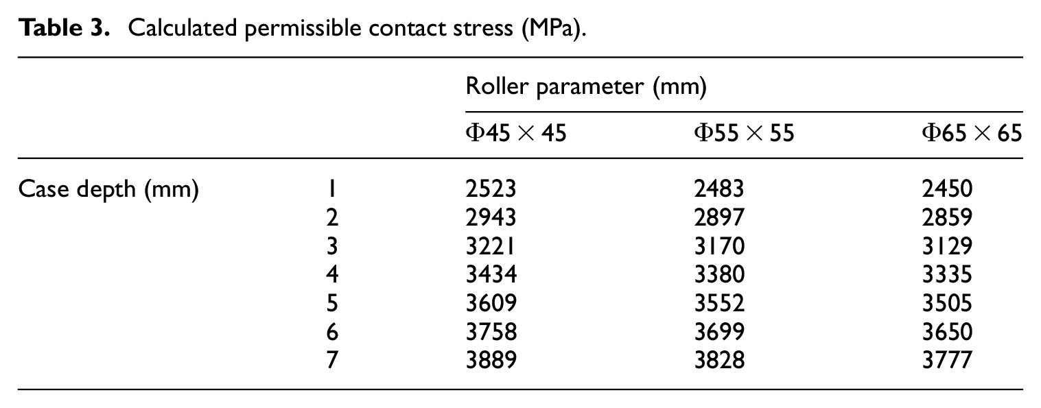
Three types of rollers were taken as examples. The raceway permissible contact stresses corresponding to different case depth were calculated by using the formula (11), as shown in Table 3. The following can be seen from the calculated results:
Permissible contact stress decreases slightly with the increase of the roller diameter.
Permissible contact stress increases with the increase of the case depth significantly.
As the case depth reaches 6 mm, the permissible contact stress is 3650−3758 MPa which reaches 91.26%−93.96% of the permissible contact stress 4000 MPa of the through hardened raceway.
As the case depth reaches 7 mm, the permissible contact stress of the case hardened raceway is 3777−3889 MPa which reaches 94.44%−97.23% of the permissible contact stress 4000 MPa of the through hardened raceway.
The permissible contact stress of the case hardened raceway mainly depends on the case depth.
Calculated permissible contact stress (MPa).
Experimental verification
To verify the validity of the established relation equation between the contact plastic deformation and the roller diameter, contact stress, case depth, two specimens with a dimension of 120 mm × 150 mm × 50 mm were made from forged material 42CrMo. They were marked as specimen
Loaded compression tests were conducted on electronic universal testing machine DNS600. The specimen

Loaded compression tests: (a) loading diagram, and (b) loaded specimen.
The comparison between the plastic contact deformations calculated by the regression equation and that measured in the experiment was shown in Figure 7. The solid lines represent the calculated results by the regression equation (10) and the square markers represent the measured results. As can be observed from the diagram, the established regression equation agrees perfectly with the experimental results. This verifies the validity of the regression equation and further verifies the validity of the established determining method of the permissible contact stress.

Experimental results: (a) roller of Φ35 mm × 35 mm, and (b) roller of Φ45 mm × 45 mm.
Conclusion
In order to establish the method for determining the permissible Hertz contact stress of the case hardened raceway of the roller slewing bearing. Finite element analysis for the contact elasto-plastic characteristics between the loaded roller and the case hardened raceway was performed, and the contact plastic deformations corresponding to different roller diameter, roller load, and case depth were obtained. The contact stress produced by the roller load was calculated by using Hertz contact theory. Based on the nonlinear regression analysis between the input parameters and the output plastic deformation, the relation equation between the contact plastic deformation and the roller diameter, contact stress, case depth was established. The formula for calculating the permissible Hertz contact stress of the case hardened raceway was obtained according to the regression equation further. The permissible raceway contact stress calculated by using the established formula show that the permissible contact stress of the case hardened raceway depends mainly on the case depth. The following can be seen from the calculated raceway permissible stresses:
Permissible contact stress decreases slightly with the increase of the roller diameter.
Permissible contact stress increases with the increase of the case depth significantly.
As the case depth reaches 6 mm, the maximum permissible contact stress is 3758 MPa which reaches 93.96% of the permissible contact stress 4000 MPa of the through hardened raceway.
As the case depth reaches 7mm, the maximum permissible contact stress of the case hardened raceway is 3889 MPa which reaches 97.23% of the permissible contact stress 4000 MPa of the through hardened raceway.
The established method for determining the permissible contact stress of the case hardened raceway is based on limiting the plastic contact deformation of the raceway surface to be 0.0001of the roller diameter. In further research, the method based on the given fatigue life of the raceway is taken into account.
Footnotes
Appendix
Authors’ contributions
LY: proposed conceptualization and methodology, performed calculating; JL: performed experiments and data processing.
Declaration of conflicting interests
The author(s) declared no potential conflicts of interest with respect to the research, authorship, and/or publication of this article.
Funding
The author(s) disclosed receipt of the following financial support for the research, authorship, and/or publication of this article: This project was supported by the National Key R&D Program of China (No.2018YFB0407304).
Ethical approval and informed consent
Topic of the paper does not based on the human subjects, thus no ethical approval and patient consent are required.